WO2015071928A1 - Dispositif de mesure de vitesse de rotation de corps mobile - Google Patents
Dispositif de mesure de vitesse de rotation de corps mobile Download PDFInfo
- Publication number
- WO2015071928A1 WO2015071928A1 PCT/JP2013/006674 JP2013006674W WO2015071928A1 WO 2015071928 A1 WO2015071928 A1 WO 2015071928A1 JP 2013006674 W JP2013006674 W JP 2013006674W WO 2015071928 A1 WO2015071928 A1 WO 2015071928A1
- Authority
- WO
- WIPO (PCT)
- Prior art keywords
- moving body
- speed
- sphere
- moving
- signal
- Prior art date
- Legal status (The legal status is an assumption and is not a legal conclusion. Google has not performed a legal analysis and makes no representation as to the accuracy of the status listed.)
- Ceased
Links
Images









Classifications
-
- G—PHYSICS
- G01—MEASURING; TESTING
- G01S—RADIO DIRECTION-FINDING; RADIO NAVIGATION; DETERMINING DISTANCE OR VELOCITY BY USE OF RADIO WAVES; LOCATING OR PRESENCE-DETECTING BY USE OF THE REFLECTION OR RERADIATION OF RADIO WAVES; ANALOGOUS ARRANGEMENTS USING OTHER WAVES
- G01S13/00—Systems using the reflection or reradiation of radio waves, e.g. radar systems; Analogous systems using reflection or reradiation of waves whose nature or wavelength is irrelevant or unspecified
- G01S13/02—Systems using reflection of radio waves, e.g. primary radar systems; Analogous systems
- G01S13/50—Systems of measurement based on relative movement of target
- G01S13/58—Velocity or trajectory determination systems; Sense-of-movement determination systems
- G01S13/583—Velocity or trajectory determination systems; Sense-of-movement determination systems using transmission of continuous unmodulated waves, amplitude-, frequency-, or phase-modulated waves and based upon the Doppler effect resulting from movement of targets
-
- G—PHYSICS
- G01—MEASURING; TESTING
- G01S—RADIO DIRECTION-FINDING; RADIO NAVIGATION; DETERMINING DISTANCE OR VELOCITY BY USE OF RADIO WAVES; LOCATING OR PRESENCE-DETECTING BY USE OF THE REFLECTION OR RERADIATION OF RADIO WAVES; ANALOGOUS ARRANGEMENTS USING OTHER WAVES
- G01S13/00—Systems using the reflection or reradiation of radio waves, e.g. radar systems; Analogous systems using reflection or reradiation of waves whose nature or wavelength is irrelevant or unspecified
- G01S13/88—Radar or analogous systems specially adapted for specific applications
Definitions
- the present invention relates to a rotation speed measuring device that measures the rotation speed of a spherical moving body.
- the following three methods are mainly known as methods for measuring the rotational speed of a moving body such as a baseball, such as a baseball pitch.
- (1) A method of taking an image of a moving sphere and calculating the number of rotations using an image analysis technique see, for example, Patent Document 1 below
- (2) Acceleration data obtained by attaching an acceleration sensor in the sphere (3) A radio wave is transmitted from an antenna as a transmission wave, and a mobile object is obtained from a frequency change between the transmission wave and a reflected wave from the mobile object.
- the Doppler method for calculating the moving speed of see, for example, Patent Documents 3 to 5 below).
- the method using the image analysis technique (1) uses a camera or the like for taking an image, so that a large-scale system is required and the introduction is costly. There is. Further, the method (1) has a problem that it is difficult to automatically measure the rotational speed, and for example, it is difficult for the user to measure the rotational speed of his own pitch.
- the Doppler method (3) generally has a problem in that it is difficult to perform stable measurement because radio wave transmission system equipment and reception system equipment are separated. Further, the method (3) has a problem that it is difficult to reduce the size of the measuring device.
- the present invention has been made in view of such circumstances, and an object thereof is to provide a rotational speed measuring device for a moving body that allows a user or the like to easily measure the rotational speed of a moving body that is a sphere. There is to do.
- a rotational speed measurement device for a moving body of the present invention has directivity, transmits a transmission wave toward a spherical mobile body based on a supplied transmission signal, and transmits the moving wave.
- An antenna that receives a reflected wave reflected by the body and generates a reception signal; supplies the transmission signal to the antenna; and generates a Doppler signal having a Doppler frequency based on the reception signal; and
- An input unit for inputting diameter information of a sphere, a measurement processing unit for calculating a moving speed and a rotational speed of the moving body based on the Doppler signal and the diameter information, and the calculated moving speed and the rotational speed It is characterized by comprising a display unit that displays display content including, and at least a housing that holds the display unit.
- the Doppler signal by using the Doppler signal, it is possible to measure the rotational speed and moving speed of the moving body in a relatively low frequency region, and therefore, measure the rotational speed and moving speed of the moving body with a simple configuration. be able to.
- FIG. 1 is a front view of a rotation speed measuring device 10.
- FIG. FIG. 3 is a view as seen from an arrow A in FIG. 2.
- FIG. 3 is a view taken in the direction of arrow B in FIG. 2.
- 1 is a block diagram showing a configuration of a rotation speed measuring device 10.
- FIG. 2 is a functional block diagram of a rotation speed measuring device 10.
- FIG. It is a diagram which shows an example of the Doppler signal Sd at the time of throwing the baseball 6. It is a diagram showing an example of signal intensity distribution data P.
- FIG. 6 is an explanatory diagram schematically showing the position of a moving body at times t1 to t4. It is a top view explaining the installation state of the rotation speed measuring device 10 in the case of measuring the baseball 6 as a moving body.
- 3 is a flowchart showing the operation of the rotation speed measuring device 10.
- FIG. 1 is a perspective view illustrating an appearance of a rotation speed measurement device 10 according to the embodiment
- FIG. 2 is a front view of the rotation speed measurement device 10.
- a rotational speed measurement device 10 for a moving body (hereinafter simply referred to as a rotational speed measurement device 10) includes a housing 12, an antenna 14, an antenna support portion 16, a display portion 18, and an input portion 20. It is comprised including.
- the housing 12 has a rectangular plate shape having a vertical thickness, a horizontal width greater than the thickness, and a front-rear length greater than the width.
- the upper surface 1202 of the housing 12 has a substantially rectangular shape with the longitudinal direction parallel to the front-rear direction of the housing 12.
- the front and rear surfaces of the upper surface 1202 are connected to the front surface 1204 and the rear surface 1206 of the housing 12, respectively.
- a lower surface 1203 facing the upper surface 1202 is provided with a female screw (camera screw) (not shown) for attaching the rotation speed measuring device 10 to a fixture such as a tripod.
- the antenna 14 is connected to the upper surface 1202 of the housing 12 via the antenna support 16.
- the antenna 14 has directivity, and transmits a transmission wave toward the mobile body based on a transmission signal supplied from a Doppler sensor 22 (see FIG. 6) described later, and reflects the reflected wave reflected by the mobile body.
- the received signal is generated and supplied to the Doppler sensor 22.
- an imaginary line extending along the direction in which the gain of the antenna 14 is maximized is defined as an imaginary axis L indicating the directivity direction of the antenna.
- the antenna 14 is configured by a rectangular plate-shaped patch antenna, and one surface in the thickness direction is a surface that transmits a transmission wave and receives a reflected wave, and the opposite side of the surface is a back surface. ing.
- a patch antenna is used as the antenna 14, it is advantageous in reducing the size of the rotation speed measuring apparatus 10.
- various conventionally known antennas such as a horn antenna can be used as the antenna 14. If the directivity angle of the antenna 14 is too narrow, there is a disadvantage that the measurement range of the moving body is limited. If the directivity angle of the antenna 14 is too wide, an unnecessary reflected wave from an object other than the mobile object to be measured. This is disadvantageous in ensuring measurement accuracy. For this reason, it is advantageous that the directivity angle of the antenna 14 is set to 5 to 90 degrees in order to suppress reception of unnecessary reflected waves from an object that is not the object of measurement while ensuring the measurement range of the moving body.
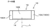
- the antenna support unit 16 is provided in the housing 12 and supports the antenna 14 so that the inclination of the virtual axis L can be changed.
- the antenna support portion 16 includes a frame 16A and a case 16B.
- the frame 16 ⁇ / b> A includes a base portion 1602 that is provided on the front surface 1204 of the housing 12 and extends in the width direction of the housing 12, and two column portions 1604 that stand forward from both ends of the base portion 1602.
- the case 16B has a rectangular plate shape that is slightly smaller than the outline when the antenna 14 is viewed in plan, and is attached to the back surface of the antenna 14 with the four sides of the case 16B parallel to the four sides of the antenna 14. Yes.
- the case 16B has a rectangular plate-like bottom wall facing the antenna 14 and four side walls standing up from the bottom wall, and the upper parts of these four side walls are connected to the back surface of the antenna 14. ing.
- a Doppler sensor 22 (to be described later) is accommodated in an accommodation space surrounded by the bottom wall, the four bottom walls, and the antenna 14.
- an integrated module in which the antenna 14 and the Doppler sensor 22 are integrally provided may be used.
- the Doppler sensor 22 is integrally provided on the back surface of the antenna 14.
- the Doppler sensor 22 may be housed in the housing 12.
- two opposite side walls of the four side walls are disposed between the two column portions 1604, and the two column portions 1604 are connected to the two column portions 1604 via a support shaft 16C whose axial center is directed in the left-right direction of the housing 12. It is rotatably supported. Therefore, the antenna support unit 16 supports the antenna 14 so that the inclination of the virtual axis L can be changed.
- an angle formed by a virtual axis L and a virtual plane P parallel to a display surface 1802 of the display unit 18 described later is defined as an antenna angle ⁇ .
- the antenna support portion 16 supports the antenna 14 so that the antenna angle ⁇ changes within a range of ⁇ 90 degrees.
- the antenna angle ⁇ changes in the range of 180 degrees.
- the adjustment range of the antenna angle ⁇ is not limited to 180 degrees, and how the adjustment range is set is arbitrary.
- the antenna angle ⁇ is +90 degrees with the virtual axis L facing upward of the housing 12, and the virtual axis L faces forward of the housing 12 as shown in FIG. 5.
- the antenna support 16 supports the antenna 14 so as to be rotatable about the single support shaft 16C.
- the antenna support 16 can change the inclination of the virtual axis L.
- various conventionally known mechanisms can be used as the antenna support portion 16.
- the antenna support unit 16 may be configured to support the antenna 14 so as to be rotatable about two support shafts by further providing another support shaft extending on a plane orthogonal to the support shaft 16C. This is more advantageous in securing the degree of freedom in adjusting the inclination of the virtual axis L of the antenna 14.
- the antenna support unit 16 includes a click mechanism that holds the antenna 14 at a plurality of predetermined antenna angles ⁇ , for example, three angles of +90 degrees, 0 degrees, and ⁇ 90 degrees. Yes. This facilitates the setting operation to a plurality of predetermined antenna angles ⁇ .
- the antenna support unit 16 is provided with an angle display unit 16D indicating which of the plurality of predetermined antenna angles ⁇ is located. It has been. This facilitates confirmation of the antenna angle ⁇ .
- the angle display portion 16D is configured by a window portion provided in one pillar portion 1604 and an index provided in the case 16B.
- the index is formed by a symbol such as A, B, or C, a numeral, a scale line, or the like at the location of the case 16B corresponding to the antenna angle ⁇ of +90 degrees, 0 degrees, and ⁇ 90 degrees.
- the antenna angle ⁇ of the antenna 14 is switched to +90 degrees, 0 degrees, and ⁇ 90 degrees, the indicators A, B, and C formed at the location of the case 16B are selectively exposed through the window. As a result, it is indicated at which of the plurality of antenna angles ⁇ the antenna 14 is located.
- Various conventionally known display mechanisms can be used as such an angle display unit 16D.
- the display unit 18 is provided on the upper surface 1202 of the housing 12 with the rectangular flat display surface 1802 facing upward, and most of the upper surface 1202 is occupied by the display surface 1802.
- the display surface 1802 has a rectangular shape whose length along the front-rear direction of the housing 12 is shorter than the width along the left-right direction of the housing 12.
- the display unit 18 causes the display surface 1802 to display various display contents including the moving speed and the number of rotations of the moving body, which are measurement results, in the form of numbers, symbols, icons, and the like.
- a flat panel display such as a liquid crystal panel can be used.
- the input unit 20 is provided near the rear surface 1206 of the upper surface 1202.
- the input unit 20 includes a plurality of operation buttons including a mode selection button and a power button.
- the display unit 18 described above may be a touch panel display, and the input unit 20 may also be used as the display unit 18.
- the power button is for turning the power on and off.
- the mode selection button is a button for selecting a measurement mode of the rotation speed measuring device 10.
- a golf mode, a bat mode, or a ball mode can be selected as a measurement mode of the rotation speed measurement device 10.
- the golf mode is a mode for measuring the hitting speed of the golf ball by the golf club.
- the bat mode is a mode for measuring the hitting speed of the baseball 6 by the baseball bat.
- the ball mode is a mode for measuring the pitching speed of the baseball 6 by the pitcher.
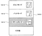
- FIG. 6 is an explanatory diagram illustrating an example of a measurement mode selection screen.
- a golf mode selection unit 1810, a bat mode selection unit 1812, and a ball mode selection unit 1814 are displayed on the display surface 1802 of the rotation speed measurement device 10 as measurement modes.
- the ball mode selection unit 1814 is selected and displayed in a color different from the other selection units.
- the user can set the measurement mode by selecting one of the selection units and performing a determination operation.
- various display modes known in the art can be used as such a measurement mode selection screen.
- the selection of the measurement mode is not necessarily accompanied by a display, and various conventionally known selection modes can be used.
- the moving body is a ball game ball
- the input unit 20 receives the type of ball game ball.
- the arithmetic unit 30 to be described later includes a database that records the diameter (diameter or radius) for each type of ball game ball, if the type of ball game ball is specified, the diameter of the sphere can be specified. Further, instead of performing the mode selection in this way, the value of the diameter of the sphere that is the moving body may be directly input to the input unit 20. In the following description, a case will be described in which the measurement mode is selected as the ball mode, and the movement speed and the number of rotations of the baseball ball 6 thrown by the user as the moving body are measured.
- the posture of the housing 12 when using the rotational speed measurement device 10 is not particularly limited, but usually (1) a posture with the upper surface 1202 (display surface 1802) of the housing 12 facing upward. (2) The posture is such that the front surface 1204 of the housing 12 faces upward and the upper surface 1202 (display surface 1802) faces sideways, and the virtual axis L of the antenna 14 matches the moving direction of the moving body. Adjust the antenna angle ⁇ .
- the rotation speed measuring device 10 may include a battery for storing electric power (not shown) and may be driven using electric power stored in the battery. Thereby, the rotation speed measuring device 10 can be installed in the vicinity of the user, and it is possible to make it difficult to get in the way of throwing or the like.
- FIG. 7 is a block diagram showing the configuration of the rotation speed measuring device 10.
- reference numeral 6 denotes a baseball ball as a spherical moving body
- reference numeral M denotes a user who throws the baseball ball 6.
- the rotation speed measurement device 10 includes a Doppler sensor 22, a measurement processing unit 24, and the like in addition to the antenna 14, the display unit 18, and the input unit 20.
- the Doppler sensor 22 is connected to the antenna 14 via a cable (not shown), supplies a transmission signal to the antenna 14 via the cable, and receives a reception signal supplied from the antenna 14 to detect the Doppler signal Sd. is there.
- the Doppler signal is a signal having a Doppler frequency Fd defined by a frequency F1-F2 that is a difference between the frequency F1 of the transmission signal and the frequency F2 of the reception signal.
- Various commercially available Doppler sensors 22 can be used.
- As the transmission signal for example, a microwave of 24 GHz or 10 GHz can be used, and the frequency of the transmission signal is not limited as long as the Doppler signal Sd can be obtained. Thereby, the versatility of the rotation speed measuring device 10 can be improved.
- the output of the transmission wave is, for example, 10 mW or less. This is because when the rotational speed measurement device 10 is battery-driven, it is desirable to keep the power consumption as low as possible in order to extend the usable time. In the rotation speed measurement device 10, the power consumed for transmitting the transmission wave from the antenna 14 is extremely large. Thus, by setting the output of the transmission wave to 10 mW or less, for example, the power consumption can be reduced and the usable time of the rotation speed measurement device 10 driven by the battery can be extended.
- the Doppler frequency Fd is expressed by Expression (1).
- V moving speed of the moving body
- c speed of light (3 ⁇ 10 8 m / s) Therefore, when equation (1) is solved for V, equation (2) is obtained.
- V c ⁇ Fd / (2 ⁇ F1) (2) That is, the moving speed V of the moving body is proportional to the Doppler frequency Fd. Therefore, the Doppler frequency Fd can be detected from the Doppler signal Sd, and the moving speed V can be obtained from the Doppler frequency Fd.
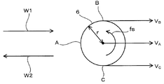
- FIG. 8 is an explanatory diagram of the principle of detecting the rotational speed of the moving body (baseball ball 6).
- the transmission wave W1 is efficiently reflected at the first portion A which is the surface portion whose angle with the transmission direction of the transmission wave W1 is close to 90 degrees (approximately 90 °).
- the intensity of the reflected wave W2 is high.
- the transmission wave W1 is efficiently reflected by the second part B and the third part C, which are parts of the surface whose angle to the transmission direction of the transmission wave W1 is close to 0 degrees (approximately 0 °).
- the intensity of the reflected wave W2 is low in the second and third portions B and C.
- the second part B is a part in which the moving direction of the moving body is opposite to the moving direction of the moving body.
- the third part C is a part in which the moving direction of the moving body is the same as the moving direction of the moving body.
- the velocity detected based on the reflected wave W2 reflected by the first portion A is the first velocity VA
- the velocity detected based on the reflected wave W2 reflected by the second portion B is the second velocity VB
- the third is the third.
- a speed detected based on the reflected wave W2 reflected by the portion C is defined as a third speed VC. Then, the following formula is established.
- VA V (4)
- VB VA- ⁇ r (5)
- VC VA + ⁇ r (6)
- V the moving speed of the moving body
- ⁇ the angular velocity (rad / s)
- r the radius of the moving body
- the speed / rotation speed calculation unit 30B described later includes a first portion A having an angle of approximately 90 ° with respect to the transmission direction of the transmission wave W1 on the surface of the moving sphere, and the transmission direction of the transmission wave W1.
- the velocity is calculated using the reflected wave from the third portion C and the same direction as the direction, and the first velocity VA calculated using the reflected wave W2 from the first portion A is the moving velocity V of the sphere.
- the second velocity VB calculated using the reflected wave W2 from the second portion B is a value obtained by subtracting the product of the angular velocity ⁇ of the sphere and the radius r of the sphere from the first moving velocity VA,
- the third velocity VC calculated using the reflected wave W2 from the third portion C is the first movement
- FIG. 9 is a diagram showing the result of wavelet analysis of the Doppler signal Sd when the rotational speed measurement device 10 measures a moving body launched by a dedicated device.
- the horizontal axis represents time t (ms), and the vertical axis represents the Doppler frequency Fd (kHz) and the moving speed V (m / s) of the moving body.
- a time t0 on the horizontal axis indicates a time when the moving object is launched.
- Such a diagram can be obtained, for example, by sampling the Doppler signal Sd, taking it into a digital oscilloscope and converting it into digital data, and performing wavelet analysis or FFT analysis on the digital data using a personal computer or the like.
- the frequency distribution indicated by the symbol DA is a portion corresponding to the first speed VA with a strong signal strength.
- the frequency distribution indicated by the symbol DB is a portion corresponding to the second speed VB having a signal intensity lower than that of the frequency distribution DA.
- the frequency distribution indicated by the reference sign DC is a portion corresponding to the third speed VC having a signal intensity lower than that of the frequency distribution DA.
- the frequency distributions DA, DB, and DC are specified, and the above equations (4), (5), and (6) are determined from the respective frequency distributions DA, DB, and DC.
- the first, second and third speeds VA, VB and VC can be obtained as time series data. That is, the speed / rotation speed calculation unit 30B described later includes a component having a relatively high signal intensity in the signal intensity distribution data of the Doppler signal Sd, a reflected wave component from the first portion A, and a relatively low signal intensity.
- a component having a frequency lower than that of the reflected wave component from the first part A is a reflected wave component from the second part B, and a component having a relatively low signal intensity is more than the reflected wave component from the first part A.
- the number of rotations of the sphere is calculated using a component having a high frequency as a reflected wave component from the third portion C.
- Such processing can be realized by using various conventionally known signal processing circuits or by using a microprocessor that operates based on a signal processing program.
- FIG. 10 is an explanatory diagram showing the positional relationship between the wavefront of the transmission wave transmitted from the antenna 14 and the moving direction of the moving body.
- the moving speed of the moving body that moves at an angle ⁇ with respect to the virtual axis L indicating the directivity of the antenna 14 is measured later by cos ⁇ than the actual moving speed.
- the transmission wave is generally a plane wave (more specifically, perpendicular to the virtual axis L). Plane wave having wavefront W). That is, the normal direction of the wavefront W of the transmission wave transmitted from the antenna 14 always coincides with the virtual axis L.
- the transmission wave is a spherical wave (more specifically, a spherical wave centered on the position of the antenna 14). . That is, the normal direction of the wavefront W of the transmission wave transmitted from the antenna 14 varies depending on the position. For this reason, the angle ⁇ between the moving direction of the moving body moving in a certain direction and the normal direction of the wavefront W varies depending on the position (in FIG. 10B, ⁇ 3 ⁇ ⁇ 4). The speed is measured with an error (delay) that varies depending on the position of the moving body.
- the measurement time It is possible to easily measure by taking an average value of the moving speeds.
- the time change of the frequency due to the angle error cannot be ignored.
- the user when the user measures his / her pitching speed and rotation speed, the user himself / herself needs to operate the rotation speed measuring device 10, and the moving start point (position of the user) The installation position of the antenna 14 (the installation position of the rotation speed measurement device 10) cannot be increased.
- the rotation speed measurement device 10 continuously measures a Doppler signal for a predetermined time after the moving body starts moving. That is, the antenna 14 continuously transmits a transmission wave and receives a reflected wave during a predetermined measurement time, and the Doppler sensor 22 supplies a transmission signal and generates a Doppler signal continuously during a predetermined measurement time. .
- the moving speed of the moving body is calculated using the peak value of the frequency, and the rotation speed of the moving body is calculated using the maximum value of the amplitude. That is, the arithmetic unit 30 (see FIG.
- the measurement processing unit 24 inputs the Doppler signal Sd supplied from the Doppler sensor 22 and performs arithmetic processing to calculate the moving speed and the number of rotations of the moving body (baseball ball 6 in the present embodiment). is there.
- the measurement processing unit 24 is configured by a microcomputer 26.
- the microcomputer 26 includes a CPU 26A, a ROM 26B, a RAM 26C, an interface 26D, a display driver 26E, and the like connected via an interface circuit (not shown) and a bus line.
- the ROM 26B stores a control program for calculating the moving speed and rotation speed of the moving body executed by the CPU 26A, and the RAM 26C provides a working area.
- the interface 26D receives the Doppler signal Sd and supplies it to the CPU 26A, and receives an operation signal from the input unit 20 and supplies it to the CPU 26A.
- the display driver 26E drives the display unit 18 based on the control of the CPU 26A.
- FIG. 11 is a block diagram of the rotation speed measuring device 10 showing the configuration of the microcomputer 26 as functional blocks.
- the microcomputer 26 is functionally configured to include a storage unit 28, a calculation unit 30, and a control unit 32.
- the storage unit 28, the calculation unit 30, and the control unit 32 are realized by the CPU 26A executing the control program. These units are configured by hardware such as a circuit. It may be a thing.
- the accumulating unit 28 accumulates the Doppler signal Sd in order as time elapses in a predetermined sampling period.
- the accumulating unit 28 accumulates the Doppler signal Sd in order as time elapses in a predetermined sampling period.
- the CPU 21A samples the Doppler signal Sd at the sampling period and stores it in the RAM 21C as sampling data of the Doppler signal Sd.
- the storage unit 28 starts the sampling operation at the same time as the power of the rotation speed measuring device 10 is turned on.
- FIG. 12 is a diagram showing an example of the Doppler signal Sd when the baseball ball 6 is thrown.
- the horizontal axis represents time t (sec), and the vertical axis represents amplitude (arbitrary unit).
- the waveform portion exhibiting the first large amplitude indicates the portion of the Doppler signal generated by the user's movement
- the subsequent waveform portion indicates the portion of the Doppler signal generated by the pitched baseball ball 6.
- the calculation unit 30 calculates the moving speed and the rotation speed of the moving body based on the Doppler signal and the diameter information of the moving body.
- the calculation unit 30 includes a signal intensity distribution data generation unit 30A and a speed / rotation number calculation unit 30B.
- the signal intensity distribution data generation unit 30A generates signal intensity distribution data by performing frequency analysis (continuous FFT analysis or wavelet analysis) on sampling data of the Doppler signal Sd accumulated in the accumulation unit 28.
- the signal intensity distribution data generation unit 30A generates signal intensity distribution data indicating a signal intensity distribution for each frequency by performing frequency analysis on the Doppler signal Sd obtained from the Doppler sensor 22.
- the signal intensity distribution data generation unit 30A specifies the sampling data of the Doppler signal Sd, which is time-series data stored in the storage unit 28, as a predetermined section, and generates signal intensity distribution data. carry out.
- the signal intensity distribution data generation unit 30A converts the Doppler signal at each time (sampling interval period) during a predetermined measurement time into signal intensity distribution data.
- the section of the sampling data of the Doppler signal Sd is specified based on a predetermined measurement time.
- the signal intensity distribution data generation unit 30A identifies the sampling data in a certain section after the baseball 2 is thrown from the sampling data of the Doppler signal Sd accumulated by the dripping method, and the signal intensity distribution Perform data generation.
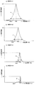
- FIG. 13 is a diagram showing an example of the signal intensity distribution data P generated by the signal intensity distribution data generation unit 30A, where (a) is a time t1, (b) is a time t2, (c) is a time t3, (D) is signal intensity distribution data at time t4 (t1 ⁇ t2 ⁇ t3 ⁇ t4).
- the horizontal axis represents frequency f (Hz)
- the vertical axis represents signal intensity (arbitrary unit).
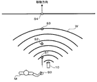
- FIG. 14 is an explanatory diagram schematically showing the position of the moving body at times t1 to t4.
- a point S ⁇ b> 0 is a moving start point of the moving body
- a wavefront W indicates a wavefront of a transmission wave transmitted from the antenna 14 of the rotation speed measurement device 10.
- the moving body (baseball ball 6) that has started moving from the movement start point S passes the point S1 in the vicinity of the rotation speed measuring device 10 at time t1, the point S2 at time t2, and the point S3 at time t3.
- the wavefront W has moved to a point S4 where it is almost a plane wave.
- FIG. 13A shows the signal intensity distribution data P at time t1 passing through the vicinity of the rotation speed measurement device 10, as shown in FIG.
- the value of the signal strength ST is the largest and the width SW of the signal strength distribution is the widest.
- the value of the signal strength ST decreases, and the signal strength The distribution width SW is also narrowed.
- the frequency (peak frequency) PK corresponding to the peak value of the signal intensity distribution increases with the passage of time (that is, the increase in the distance between the moving body and the rotation speed measuring device 10).
- a speed measurement error based on the angle error occurs and the movement speed Is actually measured late.
- the distance between the moving body and the rotation speed measuring device 10 has increased.
- the angle error has been reduced, the angle error has been eliminated, so the frequency value approaches the value indicating the true moving speed.
- the speed / rotation number calculation unit 30 ⁇ / b> B calculates the moving speed and the rotation number of the moving body based on the signal intensity distribution data P. More specifically, the speed / rotation speed calculation unit 30B calculates the moving speed using the peak value PK of the Doppler frequency, and uses the width SW of a predetermined frequency band centered on the peak value (more specifically, Calculates the rotational speed of the moving body (using the signal intensity distribution data of the Doppler signal Sd at the time when the width SW takes the maximum value).
- the predetermined frequency band centered on the peak value is the width between points at which the signal intensity is lower than the peak value by a predetermined level on the high frequency side and low frequency side of the Doppler frequency, that is, the signal intensity on the high frequency side of the Doppler signal. It refers to the width between the point where the peak level is lower by a predetermined level and the point where the signal intensity is lower than the peak value by a predetermined level on the low frequency side of the Doppler signal.
- the speed / rotation speed calculation unit 30B calculates the moving speed using the peak value of the Doppler frequency, and calculates the peak value at the point where the signal intensity is lower than the peak value by a predetermined level on the high frequency side of the Doppler signal.
- the number of rotations may be calculated using the width between the points to be taken. This is because, on the low frequency side, compared to the high frequency side, there is a high possibility that a noise component caused by an obstacle other than the moving body (for example, the body of the pitcher who throws the baseball ball 6) is included. It is.
- the speed / rotation speed calculation unit 30B is the maximum value of the peak value PK among the Doppler signals obtained continuously during a predetermined measurement time (for example, FIGS. 13A to 13D). Is used to calculate the moving speed, and the rotational speed is calculated using the maximum value of the frequency band width SW. Taking FIG. 13 as an example, the moving speed is calculated using the peak value (peak frequency) PK in FIG. 13D, and the rotational speed is calculated using the frequency width SW in FIG. Specific calculation formulas are as the above formulas (1) to (6).
- the speed / revolution number calculation unit 30B calibration is performed in advance for each sphere diameter information (for example, for each type of ball for ball game), and a correlation equation for the peak frequency PK and the moving speed, and a correlation for the frequency width SW and the rotation number.
- An equation may be generated, and a correlation equation may be selected based on the diameter information input to the input unit 20 to calculate the moving speed and the rotation speed. This is because various noises that cause measurement errors occur during actual measurement, and by using a correlation equation, it is possible to calculate the movement speed and the rotational speed closer to the true values from the measurement data.
- the control part 32 receives operation of the input part 20, and sets any measurement mode of a golf mode, a bat mode, and a ball mode. Further, the control unit 32 causes the display unit 18 to display the calculated moving speed and rotation speed of the moving body.
- FIG. 15 is a plan view illustrating an installation state of the rotation speed measurement device 10 when the baseball ball 6 is measured as a moving body.
- FIG. 16 is a flowchart showing the operation of the rotation speed measurement apparatus 10 when measuring the baseball ball 6 as a moving body.
- the rotation speed measurement device 10 displays a mode selection screen on the display surface 1802 (step S10), and waits until a measurement mode is selected (step S12: No loop).
- the user M operates the mode selection button to select the measurement mode of the rotation speed measurement device 10.
- the user M selects the ball mode from among the golf mode, the bat mode, and the ball mode.
- a screen for inputting the diameter (diameter, radius, etc.) of a sphere that is a moving body may be displayed.
- the rotation speed measurement device 10 specifies diameter information of a ball for a ball game that becomes a moving body in the selected mode (step S14).
- the user M is, for example, 1.5 m to 2 m from the standing position of the user M in the pitching direction of the baseball ball 6 (the direction along the straight line connecting the home base and the pitcher).
- the rotational speed measuring device 10 is installed at a location about 0 m in front. That is, the upper surface 1202 (display surface 1802) of the rotation speed measurement device 10 is directed in the direction opposite to the pitching direction, the front surface 1204 is directed upward, and the rear surface 1206 is directed to the ground.
- the antenna angle ⁇ of the antenna 14 is adjusted so that the virtual axis L coincides with the pitching direction. In this case, the antenna angle ⁇ is, for example, ⁇ 90 degrees.
- the rotation speed measuring device 10 may be placed on the ground, or may be installed via a fixture such as a tripod. As a result, the transmission wave W1 transmitted from the antenna 14 strikes the baseball ball 6, and the reflected wave W2 becomes receivable by the antenna 14. Further, the user M can easily see the display surface 1802. In addition, when measuring the moving speed and the number of rotations of another ball game ball such as a golf ball as a moving body, the number of rotations is measured, for example, about 1.5 m to 2.0 m ahead from the movement starting position of the moving body. The apparatus 10 is installed.
- the measuring operation by the rotation speed measuring device 10 is executed. Specifically, the transmission wave W1 is reflected by the baseball ball 6, the reflected wave W2 is received by the Doppler sensor 22, and the Doppler sensor 22 generates the Doppler signal Sd (Step S16).
- the Doppler signal Sd is sampled at the sampling period by the storage unit 28 and stored as time-series data in the storage unit 28 (step S18).
- step S20 No loop
- the process returns to step S16, and generation and accumulation of the Doppler signal Sd are continued.
- the signal intensity distribution data generation unit 30A generates signal intensity distribution data P at each sampling time within the measurement time (step S22).
- the speed / rotation speed calculation unit 30B identifies the time at which the value of the peak frequency PK is the maximum among the signal intensity distribution data P generated in step S22 (step S24). Then, the speed / revolution number calculation unit 30B calculates the moving speed of the baseball 6 using the peak frequency PK at the specified time (step S26).
- the speed / rotation speed calculation unit 30B specifies the time at which the frequency band width SW is the maximum among the signal intensity distribution data P generated in step S18 (step S28). Then, the speed / rotational speed calculation unit 30B calculates the rotational speed of the baseball 6 using the frequency band width SW at the specified time (step S30). At this time, the diameter information specified in step S14 is used to calculate the rotation speed.
- the control unit 32 causes the display surface 1802 to display information including the moving speed calculated in step S26 and the rotation speed calculated in step S30 on the display surface 1802 (step S32), and ends the measurement operation.
- the display format of the measurement data is arbitrary. Specifically, for example, by performing an operation on the input unit 20 for setting a display mode for selecting a display form, the control unit 32 accepts the operation and displays both or one of the movement speed and the rotation speed. You can make it.
- the rotation speed and movement speed of the moving body can be measured in a relatively low frequency region.
- the rotational speed and moving speed of the moving body can be measured with a simple configuration.
- the rotation speed measurement device 10 calculates the moving speed using the maximum value of the peak frequency among the Doppler signals Sd obtained continuously during a predetermined measurement time, and uses the maximum value of the frequency width SW. Calculate the number of revolutions. Thereby, even when the moving body moves in the vicinity of the rotation speed measuring device 10, it is difficult to be influenced by the angle error, and the measurement accuracy can be improved.
- the rotational speed measurement apparatus 10 inputs the diameter information of the spherical body which is a moving body via the input part 20, it can acquire easily the diameter information indispensable for calculation of the rotational speed of a moving body. For example, if the type of ball game ball is input from the input unit 20, the number of revolutions can be measured without the user directly knowing the diameter information of the sphere. Further, for example, if the value of the diameter of the sphere is input from the input unit 20, a case where a sphere having a special size is used for measurement can be dealt with.
- the rotation speed measurement device 10 if a correlation equation is generated in advance for each sphere diameter information and the correlation equation is selected based on the diameter information to calculate the moving speed and the rotation speed, The influence of various noises that occur can be reduced, and the calculation accuracy of the moving speed and the rotational speed can be improved.
- the frequency band of the transmission wave is 24 GHz or 10 GHz, the versatility of the rotation speed measuring device 10 can be enhanced.
- the output of the transmission wave is 10 mW or less in the rotation speed measurement device 10, the power consumption in the rotation speed measurement device 10 can be reduced, and the rotation speed measurement device 10 is also practical when it is driven by a battery. Can be improved.
- the rotational speed measuring device 10 is configured as an integrated module in which the antenna 14 and the Doppler sensor 22 are integrally provided, the rotational speed measuring device 10 can be further reduced in size, which is possible. Portability can be improved. Moreover, since the installation area of the rotation speed measuring device 10 can be reduced, even if it is installed near the user or the like, it can be made difficult to get in the way. Further, if the rotational speed measurement device 10 is driven using the electric power stored in the battery, the measurement can be performed regardless of the measurement location, and the convenience of the rotational speed measurement device 10 is improved. Can do.
- the antenna support unit 16 supports the antenna 14 in a range where the antenna angle ⁇ between the virtual axis L and the virtual plane P parallel to the flat display surface 1802 of the display unit 18 is ⁇ 90 degrees. It is made to change. Therefore, since the direction of the display surface 1802 and the direction of the virtual axis L of the antenna 14 can be adjusted from the same direction to the opposite direction, the visibility of the display unit 18 and the measurement accuracy of the moving speed of the moving body can be improved. It is more advantageous in securing both.
- a baseball is described as an example in the ball mode.
- a moving object to be measured is a golf ball, a soccer ball, a volleyball, a tennis ball, a handball, or a throw.
- Cannonballs are optional in competitions.
Landscapes
- Engineering & Computer Science (AREA)
- Radar, Positioning & Navigation (AREA)
- Remote Sensing (AREA)
- Physics & Mathematics (AREA)
- Computer Networks & Wireless Communication (AREA)
- General Physics & Mathematics (AREA)
- Electromagnetism (AREA)
- Radar Systems Or Details Thereof (AREA)
Abstract
Priority Applications (3)
| Application Number | Priority Date | Filing Date | Title |
|---|---|---|---|
| KR1020167009620A KR101810440B1 (ko) | 2013-11-13 | 2013-11-13 | 이동체의 회전수 계측 장치 |
| PCT/JP2013/006674 WO2015071928A1 (fr) | 2013-11-13 | 2013-11-13 | Dispositif de mesure de vitesse de rotation de corps mobile |
| US15/036,676 US10379213B2 (en) | 2013-11-13 | 2013-11-13 | Moving body rotation speed measurement device |
Applications Claiming Priority (1)
| Application Number | Priority Date | Filing Date | Title |
|---|---|---|---|
| PCT/JP2013/006674 WO2015071928A1 (fr) | 2013-11-13 | 2013-11-13 | Dispositif de mesure de vitesse de rotation de corps mobile |
Publications (1)
| Publication Number | Publication Date |
|---|---|
| WO2015071928A1 true WO2015071928A1 (fr) | 2015-05-21 |
Family
ID=53056900
Family Applications (1)
| Application Number | Title | Priority Date | Filing Date |
|---|---|---|---|
| PCT/JP2013/006674 Ceased WO2015071928A1 (fr) | 2013-11-13 | 2013-11-13 | Dispositif de mesure de vitesse de rotation de corps mobile |
Country Status (3)
| Country | Link |
|---|---|
| US (1) | US10379213B2 (fr) |
| KR (1) | KR101810440B1 (fr) |
| WO (1) | WO2015071928A1 (fr) |
Cited By (1)
| Publication number | Priority date | Publication date | Assignee | Title |
|---|---|---|---|---|
| JP2014062882A (ja) * | 2012-09-03 | 2014-04-10 | Yokohama Rubber Co Ltd:The | 移動体の回転数計測装置 |
Families Citing this family (12)
| Publication number | Priority date | Publication date | Assignee | Title |
|---|---|---|---|---|
| EP3098624A1 (fr) | 2004-07-02 | 2016-11-30 | Trackman A/S | Procédé et appareil pour déterminer un écart entre une direction réelle d'un projectile lancé et une direction prédéterminée |
| KR101845503B1 (ko) | 2009-01-29 | 2018-04-04 | 트랙맨 에이/에스 | 레이더 및 촬상 요소를 포함하는 조립체 |
| JP2015170174A (ja) * | 2014-03-07 | 2015-09-28 | ソニー株式会社 | 情報処理装置、情報処理システム、情報処理方法及びプログラム |
| US10379214B2 (en) | 2016-07-11 | 2019-08-13 | Trackman A/S | Device, system and method for tracking multiple projectiles |
| US10444339B2 (en) | 2016-10-31 | 2019-10-15 | Trackman A/S | Skid and roll tracking system |
| US10989791B2 (en) | 2016-12-05 | 2021-04-27 | Trackman A/S | Device, system, and method for tracking an object using radar data and imager data |
| KR101931592B1 (ko) | 2017-12-12 | 2019-03-13 | 주식회사 골프존 | 운동하는 볼에 대한 센싱장치 및 이를 이용한 볼에 대한 운동 파라미터 산출방법 |
| JP7052369B2 (ja) * | 2018-01-19 | 2022-04-12 | カシオ計算機株式会社 | データ解析装置、データ解析方法及びプログラム |
| KR102292353B1 (ko) | 2018-12-28 | 2021-08-23 | 주식회사 골프존 | 레이더 센싱데이터를 이용한 골프클럽의 스윙궤적 산출방법 및 이를 이용한 레이더 센싱장치와, 상기 방법을 기록한 컴퓨팅장치에 의해 판독 가능한 기록매체 |
| US10935657B2 (en) * | 2019-05-07 | 2021-03-02 | Applied Concepts, Inc. | System and method for precision spin measurement using doppler radar |
| US12264895B2 (en) * | 2020-05-20 | 2025-04-01 | Laser Technology, Inc. | Systems and techniques for facilitating archery |
| SE544234C2 (en) * | 2020-06-03 | 2022-03-08 | Topgolf Sweden Ab | Method for determing spin of a projectile |
Citations (10)
| Publication number | Priority date | Publication date | Assignee | Title |
|---|---|---|---|---|
| US6244971B1 (en) * | 1999-01-28 | 2001-06-12 | The Distancecaddy Company, Llc | Spin determination for a rotating object |
| JP2003043141A (ja) * | 2001-07-31 | 2003-02-13 | Toto Ltd | 回転数測定装置 |
| JP2003294777A (ja) * | 2002-03-29 | 2003-10-15 | Techno Network Shikoku Co Ltd | 回転数検出装置、物体計測システムおよび回転数検出方法 |
| JP2008538085A (ja) * | 2005-03-03 | 2008-10-09 | インタラクティブ・スポーツ・ゲームズ・アクティーゼルスカブ | スポーツボールの回転パラメータの決定 |
| WO2011074247A1 (fr) * | 2009-12-14 | 2011-06-23 | 横浜ゴム株式会社 | Balle pour jeu de balle et procédé de fabrication de celle-ci |
| JP2012068163A (ja) * | 2010-09-24 | 2012-04-05 | Yokohama Rubber Co Ltd:The | ボール計測装置 |
| JP2012068139A (ja) * | 2010-09-24 | 2012-04-05 | Yokohama Rubber Co Ltd:The | ボール計測装置およびボール計測方法 |
| WO2012169179A1 (fr) * | 2011-06-09 | 2012-12-13 | 横浜ゴム株式会社 | Balle pour jeux de balle |
| WO2013076980A1 (fr) * | 2011-11-24 | 2013-05-30 | 横浜ゴム株式会社 | Procédé et dispositif de mesure de comportement pour tête de club de golf et procédé et dispositif de mesure de comportement pour équipements de frappe |
| JP2013130569A (ja) * | 2011-11-25 | 2013-07-04 | Yokohama Rubber Co Ltd:The | 移動体の速度計測装置 |
Family Cites Families (8)
| Publication number | Priority date | Publication date | Assignee | Title |
|---|---|---|---|---|
| US5246232A (en) * | 1992-01-22 | 1993-09-21 | Colorado Time Systems | Method and apparatus for determining parameters of the motion of an object |
| JP3279984B2 (ja) * | 1998-08-04 | 2002-04-30 | 明星電気株式会社 | 飛翔体計測評価方法 |
| US20020107078A1 (en) * | 2000-12-11 | 2002-08-08 | Collins Robert J. | Detecting movement characteristics of an object |
| US7046190B2 (en) * | 2003-07-25 | 2006-05-16 | Raytheon Company | Process for phase-derived range measurements |
| JP4234667B2 (ja) * | 2004-11-30 | 2009-03-04 | 株式会社東芝 | 移動体用ofdm受信装置 |
| JP4723876B2 (ja) | 2005-02-23 | 2011-07-13 | 株式会社ジャパーナ | 空間を移動する球体の回転方向と回転量の測定方法及び空間を移動する際の回転方向と回転量測定に適した球体 |
| JP5196581B2 (ja) | 2009-04-22 | 2013-05-15 | 国立大学法人信州大学 | 球体の回転検出装置及び方法 |
| JP2012233773A (ja) * | 2011-04-28 | 2012-11-29 | Yokohama Rubber Co Ltd:The | 移動体の速度計測装置 |
-
2013
- 2013-11-13 WO PCT/JP2013/006674 patent/WO2015071928A1/fr not_active Ceased
- 2013-11-13 KR KR1020167009620A patent/KR101810440B1/ko not_active Expired - Fee Related
- 2013-11-13 US US15/036,676 patent/US10379213B2/en active Active
Patent Citations (10)
| Publication number | Priority date | Publication date | Assignee | Title |
|---|---|---|---|---|
| US6244971B1 (en) * | 1999-01-28 | 2001-06-12 | The Distancecaddy Company, Llc | Spin determination for a rotating object |
| JP2003043141A (ja) * | 2001-07-31 | 2003-02-13 | Toto Ltd | 回転数測定装置 |
| JP2003294777A (ja) * | 2002-03-29 | 2003-10-15 | Techno Network Shikoku Co Ltd | 回転数検出装置、物体計測システムおよび回転数検出方法 |
| JP2008538085A (ja) * | 2005-03-03 | 2008-10-09 | インタラクティブ・スポーツ・ゲームズ・アクティーゼルスカブ | スポーツボールの回転パラメータの決定 |
| WO2011074247A1 (fr) * | 2009-12-14 | 2011-06-23 | 横浜ゴム株式会社 | Balle pour jeu de balle et procédé de fabrication de celle-ci |
| JP2012068163A (ja) * | 2010-09-24 | 2012-04-05 | Yokohama Rubber Co Ltd:The | ボール計測装置 |
| JP2012068139A (ja) * | 2010-09-24 | 2012-04-05 | Yokohama Rubber Co Ltd:The | ボール計測装置およびボール計測方法 |
| WO2012169179A1 (fr) * | 2011-06-09 | 2012-12-13 | 横浜ゴム株式会社 | Balle pour jeux de balle |
| WO2013076980A1 (fr) * | 2011-11-24 | 2013-05-30 | 横浜ゴム株式会社 | Procédé et dispositif de mesure de comportement pour tête de club de golf et procédé et dispositif de mesure de comportement pour équipements de frappe |
| JP2013130569A (ja) * | 2011-11-25 | 2013-07-04 | Yokohama Rubber Co Ltd:The | 移動体の速度計測装置 |
Cited By (1)
| Publication number | Priority date | Publication date | Assignee | Title |
|---|---|---|---|---|
| JP2014062882A (ja) * | 2012-09-03 | 2014-04-10 | Yokohama Rubber Co Ltd:The | 移動体の回転数計測装置 |
Also Published As
| Publication number | Publication date |
|---|---|
| US20160327642A1 (en) | 2016-11-10 |
| KR101810440B1 (ko) | 2017-12-20 |
| US10379213B2 (en) | 2019-08-13 |
| KR20160054013A (ko) | 2016-05-13 |
Similar Documents
| Publication | Publication Date | Title |
|---|---|---|
| WO2015071928A1 (fr) | Dispositif de mesure de vitesse de rotation de corps mobile | |
| JP6213242B2 (ja) | 移動体の計測装置および計測方法 | |
| JP6048120B2 (ja) | 移動体の回転数計測装置 | |
| JP2013130569A (ja) | 移動体の速度計測装置 | |
| JP5273359B2 (ja) | 速度測定装置 | |
| US20130065711A1 (en) | Swing analysis method | |
| US20160107027A1 (en) | Motion capture and analysis | |
| JP5617481B2 (ja) | ボール計測装置 | |
| JP5544472B2 (ja) | 速度測定装置およびプログラム | |
| JP5824857B2 (ja) | 球技用シミュレータ装置および球技用シミュレーション方法 | |
| JP5182266B2 (ja) | 移動体の速度計測装置 | |
| JP2012233773A (ja) | 移動体の速度計測装置 | |
| JP6361134B2 (ja) | スイング評価装置およびスイング評価方法 | |
| JP6201121B2 (ja) | 角度測定装置、角度測定方法及びプログラム | |
| JP7113545B2 (ja) | 速度測定装置およびプログラム | |
| JP5682190B2 (ja) | 移動体の計測方法および計測装置 | |
| JP5802884B2 (ja) | 速度測定装置 | |
| JP2015181498A (ja) | 移動体の速度計測装置 | |
| KR101231046B1 (ko) | 골프공 추적 장치 및 방법 | |
| JP7853557B2 (ja) | 評価システム、評価装置、評価方法、及びプログラム | |
| JP2014140764A (ja) | 速度測定装置およびプログラム | |
| JP2015198761A (ja) | 運動解析装置、運動解析方法、運動解析プログラム、および運動解析表示方法 | |
| JP2018047252A (ja) | 速度測定装置およびプログラム | |
| JP6491979B2 (ja) | 速度測定装置およびプログラム |
Legal Events
| Date | Code | Title | Description |
|---|---|---|---|
| 121 | Ep: the epo has been informed by wipo that ep was designated in this application |
Ref document number: 13897303 Country of ref document: EP Kind code of ref document: A1 |
|
| ENP | Entry into the national phase |
Ref document number: 20167009620 Country of ref document: KR Kind code of ref document: A |
|
| NENP | Non-entry into the national phase |
Ref country code: DE |
|
| WWE | Wipo information: entry into national phase |
Ref document number: 15036676 Country of ref document: US |
|
| 122 | Ep: pct application non-entry in european phase |
Ref document number: 13897303 Country of ref document: EP Kind code of ref document: A1 |
|
| NENP | Non-entry into the national phase |
Ref country code: JP |