WO2015072018A1 - Moteur commuté, ventilateur électrique, aspirateur électrique et procédé de fabrication de moteur commuté - Google Patents
Moteur commuté, ventilateur électrique, aspirateur électrique et procédé de fabrication de moteur commuté Download PDFInfo
- Publication number
- WO2015072018A1 WO2015072018A1 PCT/JP2013/080922 JP2013080922W WO2015072018A1 WO 2015072018 A1 WO2015072018 A1 WO 2015072018A1 JP 2013080922 W JP2013080922 W JP 2013080922W WO 2015072018 A1 WO2015072018 A1 WO 2015072018A1
- Authority
- WO
- WIPO (PCT)
- Prior art keywords
- stator core
- rotor
- steel sheet
- commutator motor
- core
- Prior art date
- Legal status (The legal status is an assumption and is not a legal conclusion. Google has not performed a legal analysis and makes no representation as to the accuracy of the status listed.)
- Ceased
Links
Images


Classifications
-
- H—ELECTRICITY
- H02—GENERATION; CONVERSION OR DISTRIBUTION OF ELECTRIC POWER
- H02K—DYNAMO-ELECTRIC MACHINES
- H02K15/00—Processes or apparatus specially adapted for manufacturing, assembling, maintaining or repairing of dynamo-electric machines
- H02K15/02—Processes or apparatus specially adapted for manufacturing, assembling, maintaining or repairing of dynamo-electric machines of stator or rotor bodies
- H02K15/021—Magnetic cores
- H02K15/022—Magnetic cores with salient poles
-
- H—ELECTRICITY
- H02—GENERATION; CONVERSION OR DISTRIBUTION OF ELECTRIC POWER
- H02K—DYNAMO-ELECTRIC MACHINES
- H02K23/00—DC commutator motors or generators having mechanical commutator; Universal AC/DC commutator motors
- H02K23/02—DC commutator motors or generators having mechanical commutator; Universal AC/DC commutator motors characterised by arrangement for exciting
- H02K23/08—DC commutator motors or generators having mechanical commutator; Universal AC/DC commutator motors characterised by arrangement for exciting having series connection of excitation windings
-
- H—ELECTRICITY
- H02—GENERATION; CONVERSION OR DISTRIBUTION OF ELECTRIC POWER
- H02K—DYNAMO-ELECTRIC MACHINES
- H02K23/00—DC commutator motors or generators having mechanical commutator; Universal AC/DC commutator motors
- H02K23/40—DC commutator motors or generators having mechanical commutator; Universal AC/DC commutator motors characterised by the arrangement of the magnet circuits
- H02K23/405—Machines with a special form of the pole shoes
Definitions
- the present invention relates to a commutator motor, an electric blower, a vacuum cleaner, and a commutator motor manufacturing method.
- An electric blower in which a blower unit and a motor are integrated is known.
- the electric blower is mounted on a vacuum cleaner or the like.
- an electric blower is used at a high speed of 30000-45000 revolutions per minute. Therefore, an electric blower uses a commutator motor including a stator having two magnetic poles and field windings, and a rotor inside the stator and having armature windings and commutators.
- the stator core has a substantially square frame shape, and includes a substantially crescent-shaped magnetic pole projecting inward from each of two sides facing each other by 180 °.
- the magnetic flux flows from the surface of the rotor core across the gap between the opposing surfaces of the stator core and the rotor core, enters the tip of one magnetic pole, splits into two hands at the back of the magnetic pole, merges through the yoke to the back of the other magnetic pole,
- the rotor core enters from the tip of the magnetic pole across the gap between the opposing surfaces of the stator core and the rotor core, crosses the rotor core in the direction connecting the two magnetic poles, returns to the initial position, and goes around.
- the yokes are the two sides of the stator core without the magnetic poles.
- the magnetic flux gradually changes its direction while drawing an arc. That is, in the conventional stator core, the direction of the magnetic flux varies depending on the location in the stator core. Therefore, as a material for the stator core, a non-oriented electrical steel sheet whose magnetic properties do not have directionality is usually used. That is, the stator core is formed by laminating and fixing the non-oriented electrical steel sheets punched out by pressing in the axial direction of the motor.
- the rolling direction of the grain-oriented electrical steel sheet having magnetic properties is called the easy magnetization direction, and the magnetic characteristics are superior to the non-oriented electrical steel sheet.
- the direction perpendicular to the rolling direction of the grain-oriented electrical steel sheet is inferior in magnetic properties to the non-oriented electrical steel sheet.
- a directional electrical steel sheet is used for a conventional stator core, the efficiency of the magnetic circuit is increased in a part where the direction of magnetic flux and the easy magnetization direction are compared with the case where a non-oriented electrical steel sheet is used, but the part where they do not match Then the efficiency of the magnetic circuit decreases. As a result, the total efficiency of the magnetic circuit decreases and the motor efficiency decreases. Therefore, it has been difficult to adopt a grain-oriented electrical steel sheet for a conventional stator core.
- Patent Document 1 discloses a technique in which a stator core is configured by combining a plurality of blocks made of laminated grain-oriented electrical steel sheets, and the direction of magnetic flux and the direction of easy magnetization are substantially matched for each block.
- Patent Document 1 has the following problems. At the base part of the magnetic pole of the stator core and the corner part of the frame shape, the magnetic flux gradually changes its direction while drawing an arc. In these portions, the direction of the magnetic flux and the direction of easy magnetization do not match sufficiently. For this reason, the technique of Patent Document 1 cannot sufficiently improve the efficiency of the magnetic circuit. Further, on the joint surface of the block, that is, the split surface of the stator core, distortion due to the stamping of the grain-oriented electrical steel sheet in the press exists in the regions on both sides with the split surface as a boundary, and the magnetic characteristics deteriorate in that region. In the technique of Patent Document 1, the split surfaces of the stator core exist at the base portion of the magnetic pole and the corner portion of the frame shape.
- the present invention has been made to solve the above-described problems, and a commutator motor and an electric motor capable of sufficiently improving the efficiency of a magnetic circuit of a commutator motor having a stator core using a directional electromagnetic steel sheet. It aims at providing a blower, a vacuum cleaner, and a commutator motor manufacturing method.
- a commutator motor of the present invention includes a stator having a stator core and a field winding, and a rotor having an armature winding and disposed inside the stator, and the stator core has a longitudinal direction as an easy magnetization direction. It is formed by laminating belt-shaped grain-oriented electrical steel sheets, and the normal line of the surface of the grain-oriented electrical steel sheet is perpendicular to the rotation axis of the rotor.
- FIG. 1 It is a longitudinal cross-sectional view which shows the electric blower of Embodiment 1 of this invention. It is sectional drawing which looked at the principal part of the commutator motor of Embodiment 1 of this invention from the blower part side of the rotating shaft direction of the rotor. It is the figure which extracted only the stator core from FIG. It is an example of the magnetic flux diagram of the commutator motor of Embodiment 1 of this invention calculated
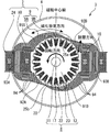
- FIG. 1 is a longitudinal sectional view showing an electric blower according to Embodiment 1 of the present invention.
- the electric blower 1 of the first embodiment includes a blower unit 2 that generates suction force and a commutator motor 3 that drives the blower unit 2.
- the electric blower 1 can be applied to a vacuum cleaner, for example.
- the blower unit 2 includes a fan 4 having a plurality of blades and a fan guide 5 that covers the fan 4.
- the fan guide 5 guides the air flowing along with the rotation of the fan 4 to the inside of the commutator motor 3. This flowing air is discharged from an opening (not shown) provided in the frame 6 while cooling the commutator motor 3 that generates heat during operation.
- the commutator motor 3 includes a stator 7 fixed inside a cup-shaped or cylindrical frame 6 and a rotor 8 disposed facing the inside of the stator 7 with a gap 20 therebetween.
- the stator 7 serves as a field.
- the rotor 8 is rotatably supported and serves as an armature. A part of the commutator motor 3 that does not fit inside the frame 6 protrudes outward from an opening or notch formed in the frame 6.
- the stator 7 includes a stator core 9 formed by laminating and fixing a plurality of directional electromagnetic steel sheets, and a field winding 10 wound around the stator core 9 via an insulating member 24. A magnetic field is generated inside the stator 7 by passing a current through the field winding 10.
- the rotor 8 is separated from the rotor core 12 by a shaft 11 disposed in the center, an annular rotor core 12 fixed around the shaft 11, an armature winding 17 wound around the rotor core 12 via an insulating member 22, and the rotor core 12. And a commutator 13 fixed around the shaft 11 at a certain position.
- the rotor core 12 is formed by laminating and fixing a plurality of electromagnetic steel plates.
- the shaft 11 is supported by the frame 6 via bearings 14 and 15. Thereby, the rotor 8 is freely rotatable with respect to the frame 6.
- One bearing 14 located on the blower unit 2 side is accommodated in a bracket 21 provided so as to cross-link across the opening of the frame 6.
- the other bearing 15 located on the side opposite to the blower unit 2 side is housed in the bottom of the frame 6.
- the fan 4 is fixed to the end portion 16 of the shaft 11 on the blower portion 2 side. As the rotor 8 rotates, the fan 4 is driven to rotate.
- the starting end or end of winding of the plurality of coils constituting the armature winding 17 and the terminal or end of winding end are electrically connected to the segment 18 of the commutator 13 by a method such as fusing or heat caulking.
- the pair of brushes 19 are held by the frame 6, pressed against the commutator 13 by a spring, and slidably contact the commutator 13.
- the brush 19 is connected to a power source (not shown) and supplies a current, that is, an armature current to the armature winding 17 via the commutator 13.
- the field winding 10 is connected in series with the armature winding 17 and supplies current to the field winding 10 from the same power source. Rotational torque is generated in the rotor 8 by the magnetic field generated by the stator 7 and the armature current. In order to make the rotation direction of the rotor 8 constant, the armature winding 17 and the segment 18 are connected so that the coil through which the armature current flows is switched in accordance with the phase of the rotor 8.
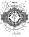
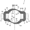
- FIG. 2 is a cross-sectional view of the main part of the commutator motor 3 according to the first embodiment as viewed from the blower part 2 side in the rotation axis direction of the rotor 8.
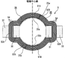
- FIG. 3 is a diagram in which only the stator core 9 is extracted from FIG.
- the rotation direction of the rotor 8 can be set by a combination of the connection between the armature winding 17 and the segment 18.
- the rotation direction of the rotor 8 is determined from the direction of the blades of the blower unit 2. In the first embodiment, it is assumed that the rotation direction of the rotor 8 is counterclockwise, that is, counterclockwise in FIG.
- the stator core 9 has an annular shape when viewed from the direction of the rotation axis of the rotor 8.
- the stator core 9 is divided into a first stator core 9A and a second stator core 9B, with two core division surfaces 25a and 25b as a boundary.
- the first stator core 9A and the second stator core 9B are substantially C-shaped.
- the core dividing surfaces 25 a and 25 b are located at positions shifted rearward in the rotational direction of the rotor 8 with respect to the magnetic pole center line of the stator core 9.
- the core split surfaces 25a and 25b are in the vicinity of the direction perpendicular to the electrical neutral axis during the rated operation of the commutator motor 3.
- the first stator core 9A includes a magnetic pole portion 91A located on the core dividing surface 25a side, a magnetic pole portion 92A located on the core dividing surface 25b side, and a winding mounting portion 93A located between the magnetic pole portions 91A and 92A.
- the second stator core 9B includes a magnetic pole portion 91B located on the core dividing surface 25b side, a magnetic pole portion 92B located on the core dividing surface 25a side, and a winding mounting portion 93B located between the magnetic pole portions 91B and 92B.
- the magnetic pole portions 91 ⁇ / b> A, 92 ⁇ / b> A, 91 ⁇ / b> B, 92 ⁇ / b> B have an arc shape centered on the rotation axis of the rotor 8.
- the field winding 10 is wound around the winding mounting portion 93A of the first stator core 9A and the winding mounting portion 93B of the second stator core 9B via the insulating member 24.
- the armature winding 17 wound around the rotor core 12 via the insulating member 22 is prevented from coming off by a wedge 23.
- the magnetic pole portion 91A of the first stator core 9A and the magnetic pole portion 92B of the second stator core 9B form one magnetic pole 26a of the stator core 9.
- the magnetic pole portion 92A of the first stator core 9A and the magnetic pole portion 91B of the second stator core 9B form the other magnetic pole 26b of the stator core 9.
- the inner peripheral sides of the magnetic poles 26a and 26b face the rotor 8 with a predetermined gap 20 therebetween.
- the first stator core 9A and the second stator core 9B have a shape bulging outward at a position substantially perpendicular to the magnetic pole center line. Due to the swollen shape, winding mounting portions 93A and 93B around which the field winding 10 is wound are formed. The winding mounting portions 93A and 93B are located farther from the rotating shaft of the rotor 8 than the magnetic pole portions 91A, 92A, 91B, and 92B. A region 30 is formed between the winding mounting portion 93 ⁇ / b> A and the outer periphery of the rotor 8, and a region 31 is formed between the winding mounting portion 93 ⁇ / b> B and the outer periphery of the rotor 8.
- the field winding 10 is mounted by a toroidal winding around the winding mounting portion 93A using the region 30 and the region 32 on the opposite side of the region 30 across the winding mounting portion 93A.
- the field winding 10 is mounted by a toroidal winding around the winding mounting portion 93B using the region 31 and the region 33 on the opposite side of the region 31 across the winding mounting portion 93B. .
- the winding direction of the field winding 10 is indicated by a dot mark and a cross mark in FIG.
- the dot mark indicates the current flow from the back of the paper to the front
- the cross mark indicates the current flow from the front of the paper to the back.
- the winding direction of the field winding 10 may be a combination of directions opposite to those in the example of FIG.
- the field winding 10 may be wound around the region 30 from the region 30 to the region 31 while avoiding interference with the rotor 8, and the region 31 on the opposite side of the rotor 8 in the rotation axis direction. There is also a method of avoiding interference with the rotor 8 and returning to the area 30 by detouring and repeating this by a predetermined number of turns.
- This method has an advantage that it is not necessary to use the regions 32 and 33 as compared with the toroidal winding. On the other hand, this method has a demerit that it is difficult to arrange windings and that the winding length is long due to the detour shape of the coil end to avoid interference with the rotor 8. For this reason, toroidal winding is usually a better choice.
- the magnetic flux generated by the field winding 10 is in a direction along the magnetic pole center line between the magnetic poles 26a and 26b.
- the electrical neutral axis is an axis perpendicular to the direction of the combined magnetic flux of the magnetic flux generated by the field winding 10 and the magnetic flux generated by the armature winding 17.
- the direction perpendicular to the electrical neutral axis is shifted backward in the rotational direction of the rotor 8 with respect to the magnetic pole center line. Accordingly, the angle between the positions of the two core dividing surfaces 25a and 25b and the magnetic pole center line is set by the balance of magnetic flux generated by the field winding 10 and the armature winding 17, respectively. Specifically, it may be determined using the result of electromagnetic field analysis or prototype evaluation.
- the stator core 9 is configured by laminating and fixing a plurality of bent directional electromagnetic steel sheets 94.
- the longitudinal direction of the band-shaped grain-oriented electrical steel sheet 94 is the easy magnetization direction.
- the normal line of the surface of each directional electromagnetic steel sheet 94 to be laminated is perpendicular to the rotation axis of the rotor 8. That is, the direction in which the directional electromagnetic steel sheets 94 are stacked is substantially perpendicular to the longitudinal direction of the magnetic path of the stator core 9 when viewed from the rotational axis direction of the rotor 8.
- the easy magnetization direction of the grain-oriented electrical steel sheet 94 is a direction along the magnetic path.
- the thickness of the laminated directional electromagnetic steel sheets 94 corresponds to the magnetic path width (width of the magnetic pole and yoke) of the stator core 9 when viewed from the direction of the rotation axis of the rotor 8. Further, the width of the belt-shaped directional electromagnetic steel sheet 94, that is, the length in the short side direction, corresponds to the length of the stator core 9 in the direction of the rotation axis of the rotor 8.
- Each of the plurality of strip-shaped directional electromagnetic steel plates 94 constituting the first stator core 9A is continuous from the magnetic pole portion 91A to the magnetic pole portion 92A via the winding mounting portion 93A.
- each of the plurality of strip-shaped directional electromagnetic steel plates 94 constituting the second stator core 9B is continuous from the magnetic pole portion 91B to the magnetic pole portion 92B via the winding mounting portion 93B.
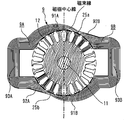
- FIG. 4 is an example of a magnetic flux diagram of the commutator motor 3 according to the first embodiment obtained by electromagnetic field analysis.
- the magnetic flux lines of the stator core 9 are along the longitudinal direction of the directional electromagnetic steel sheet 94, that is, the easy magnetization direction, except for the vicinity of the core dividing surfaces 25a and 25b.
- the direction and direction of the magnetic flux is substantially the same.
- the grain-oriented electrical steel sheet 94 has excellent magnetic properties in the easy magnetization direction, but is inferior in the perpendicular magnetic properties. According to the commutator motor 3 of the first embodiment, the degree of coincidence between the direction of the magnetic flux of the stator core 9 and the direction of easy magnetization of the directional electromagnetic steel sheet 94 is increased without increasing the number of divisions of the stator core 9. be able to. Therefore, in the stator core 9, only the better magnetic properties of the grain-oriented electrical steel sheet 94 can be mainly utilized, so that the efficiency of the magnetic circuit can be improved. As a result, the efficiency of the commutator motor 3 and the electric blower 1 can be improved.
- the core split surfaces 25a and 25b of the stator core 9 are located behind the magnetic pole center line in the rotational direction of the rotor 8 when viewed from the rotational axis direction of the rotor 8.
- the following effects can be obtained by being in the vicinity of the direction perpendicular to the electrical neutral axis.
- the magnetic flux lines are divided into two circuits, a circuit that circulates on the left side and a circuit that circulates on the right side across a straight line connecting the core split surfaces 25a and 25b in the vicinity of the direction perpendicular to the electrical neutral axis. Divided into For this reason, the magnetic flux does not cross the core dividing surfaces 25a and 25b. Therefore, in this Embodiment 1, since the influence of the efficiency fall by magnetic flux crossing the division
- the magnetic flux density is low in the vicinity of the core dividing surfaces 25a and 25b, even if the core dividing surfaces 25a and 25b are slightly deviated from the direction perpendicular to the electrical neutral axis, the influence is small. That is, the same effect as described above can be obtained even if the core split surfaces 25a and 25b are slightly deviated from the direction perpendicular to the electrical neutral axis. Therefore, the above effect can be achieved even if the electrical neutral axis is slightly deviated due to a change in the balance of magnetic flux due to a change in load during operation of the commutator motor 3.
- the first stator core 9A and the second stator core 9B are welded to the core dividing surfaces 25a and 25b after the field winding 10 is mounted. You may join using methods, such as adhesion
- the magnetic flux lines rotate relative to the rotor core 12 as the rotor 8 rotates.
- FIG. 5 is a schematic diagram showing a flyer winding machine that is an example of an automatic machine that performs aligned winding of the field winding 10.
- the flyer winding machine shown in FIG. 5 includes a core fixing jig 27 for fixing the first stator core 9A or the second stator core 9B, and a flyer arm 28 having a nozzle 29 for guiding the wire 34 at the tip.
- the core fixing jig 27 fixes the first stator core 9A or the second stator core 9B so that the rotation axis of the flyer arm 28 and the central axis of the winding mounting portion 93A or 93B coincide.
- the wire 34 is fed out from the nozzle 29 through the flyer arm 28.
- the flyer arm 28 moves in the direction of its rotation axis while rotating.
- the field winding 10 can be formed by winding the wire 34 around the winding mounting portion 93A of the first stator core 9A or the winding mounting portion 93B of the second stator core 9B. it can.
- the position where the wire 34 is placed is controlled by controlling the rotation of the flyer arm 28 and the movement in the direction of the rotation axis in synchronization.
- the wire 34 normally uses a copper wire or an aluminum wire having a diameter of 2 mm or less, its rigidity is small.
- the bending history remains on the wire 34 due to the deformation history until the nozzle 29 is inserted.
- the wire 34 coming out from the outlet of the nozzle 29 may not be straight, the position where the wire 34 is placed may be shifted from the target position, and the aligned windings may be disturbed. In order to suppress this phenomenon, the closer the nozzle 29 is to the surface on which the wire 34 is placed, the better.
- the aligned winding that the left and right spaces of the field winding 10 are opened and the nozzle 29 can be brought closer.
- the nozzle 29 can be brought close to the winding mounting portion 93A or 93B.
- Ten aligned windings can be easily and accurately performed. The situation is the same in the case where a so-called spindle winding method is adopted in which the nozzle 29 is fixed and the first stator core 9A or the second stator core 9B is rotated. Is obtained.
- Embodiment 2 the second embodiment of the present invention will be described with reference to FIG. 6 to FIG. 8.
- the description will focus on the differences from the first embodiment described above, and the same or corresponding parts will be denoted by the same reference numerals. The description is omitted.
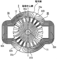
- FIG. 6 is a cross-sectional view of the main part of the commutator motor 3 according to the second embodiment as viewed from the blower part 2 side in the rotation axis direction of the rotor 8.
- FIG. 7 shows only the stator core 9 extracted from FIG. As shown in FIGS. 6 and 7, in the second embodiment, in the magnetic pole portions 91 ⁇ / b> A, 92 ⁇ / b> A, 91 ⁇ / b> B, and 92 ⁇ / b> B of the stator core 9, The number of layers gradually decreases.
- the end portions 941 of the plurality of layers of the directional electromagnetic steel sheet 94 face the rotor 8. That is, the end portion 941 of each layer of the laminated grain-oriented electrical steel sheets 94 forms a surface facing the rotor 8, that is, the inner peripheral surface of the stator core 9.
- the distance between the end portion 941 of the grain-oriented electrical steel sheet 94 and the core dividing surfaces 25a and 25b increases as the layer becomes closer to the magnetic pole portions 91A, 92A, 91B, and 92B. The closer to the core dividing surfaces 25a, 25b, the smaller the magnetic path width of the stator core 9 becomes.
- the configuration as described above makes the intervals between the magnetic flux lines more uniform, and the magnetic flux density in each directional electromagnetic steel sheet 94 becomes more uniform.
- the degree of coincidence with the easy magnetization direction of the grain-oriented electrical steel sheet 94 can be further increased as compared with the first embodiment.
- FIG. 8 is an example of a magnetic flux diagram of the commutator motor 3 of the second embodiment obtained by electromagnetic field analysis.
- the magnetic flux lines are divided into two circuits, a circuit that circulates on the left side and a circuit that circulates on the right side across a straight line connecting the core dividing surfaces 25a and 25b in the vicinity of the direction perpendicular to the electrical neutral axis.
- Divided into Magnetic flux lines from the rotor core 12 to the stator core 9 near the core dividing surface 25a cross from the stator core 9 to the rotor core 12 near the core dividing surface 25b.
- the magnetic flux lines extending from the rotor core 12 to the stator core 9 at a location far from the core dividing surface 25a pass from the stator core 9 to the rotor core 12 at a location far from the core dividing surface 25b. Accordingly, the number of magnetic flux lines in the magnetic poles 26a and 26b is small near the core dividing surfaces 25a and 25b, and gradually increases as the distance from the core dividing surfaces 25a and 25b increases. In the second embodiment, the closer to the core dividing surfaces 25a and 25b, the smaller the magnetic path width, so that the intervals between the magnetic flux lines become more uniform and the magnetic flux density becomes more uniform.
- the laminated end portions 941 are used as surfaces facing the rotor 8, that is, the inner peripheral surfaces of the stator core 9, and the directional electromagnetic steel sheets 94 are closer to the core dividing surfaces 25 a and 25 b.
- the efficiency of the magnetic circuit can be further improved as compared with the first embodiment.
- the efficiency of the commutator motor 3 and the electric blower 1 can be further improved.
- the amount of the directional electromagnetic steel sheet 94 used can be reduced compared to the first embodiment, and the commutator motor 3 and the electric blower 1 can be reduced in weight.
- Embodiment 3 the third embodiment of the present invention will be described with reference to FIGS. 9 and 10.
- the third embodiment will be described mainly with respect to the differences from the above-described embodiments, and the same or corresponding parts will be denoted by the same reference numerals. The description is omitted.
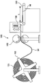
- FIG. 9 is a schematic diagram showing an example of the cutting process of the commutator motor manufacturing method according to the third embodiment of the present invention.
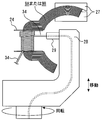
- FIG. 10 is a schematic diagram illustrating an example of a bending process of the commutator motor manufacturing method according to the third embodiment of the present invention.
- the commutator motor manufacturing method of the third embodiment is a method of manufacturing the commutator motor 3 of the present invention.
- the commutator motor manufacturing method according to the third embodiment is characterized by the process of manufacturing the stator core 9.
- the process of manufacturing the stator core 9 includes a cutting process, a bending process, and a lamination fixing process of the grain-oriented electrical steel sheet 94.
- the grain-oriented electrical steel sheet 94 is cut into a rectangular strip having a predetermined length L and width W.
- the longitudinal direction of the grain-oriented electrical steel sheet 94 that is, the direction of the length L is the easy magnetization direction.
- the length L of the directional electromagnetic steel sheets 94 of each layer stacked in the first stator core 9A or the second stator core 9B corresponds to the magnetic path length of each layer and is different.
- the width W of the directional electromagnetic steel sheet 94 that is, the length in the short side direction, corresponds to the length of the stator core 9 in the direction of the rotation axis of the rotor 8. For this reason, the width W of the directional electrical steel sheet 94 of each layer is equal.
- the apparatus 100 used in the cutting process includes an uncoiler 102 that feeds the directional electromagnetic steel plate 94 from the coil material 101, a roll feeder 103 that feeds the directional electromagnetic steel plate 94 fed from the uncoiler 102 with a pair of rollers, and a roll feeder 103. And a discharge mechanism 105 for discharging the directional electromagnetic steel sheet 94 cut by the blade 104.
- the cutting method may be any method such as shearing or pressing.
- the length L of the grain-oriented electrical steel sheet 94 varies depending on the position in the stacking direction of the first stator core 9A or the second stator core 9B. For this reason, in the cutting process, it is necessary to change the length L of the grain-oriented electrical steel sheet 94 for each sheet.
- the apparatus 100 has a servo mechanism that controls the relative position of the blade 104 with respect to the longitudinal direction of the grain-oriented electrical steel sheet 94. That is, the apparatus 100 has a servo mechanism that controls the feed amount of the directional electromagnetic steel sheet 94 according to the roll rotation angle of the roll feeder 103 and the timing to lower the blade 104.
- the length L of the directional electromagnetic steel sheet 94 can be controlled. According to the cutting process using such an apparatus 100, the grain-oriented electrical steel sheets 94 having different lengths L for each sheet can be manufactured with high productivity.
- the configuration of the servo mechanism that controls the relative position of the blade 104 with respect to the longitudinal direction of the grain-oriented electrical steel sheet 94 is not limited to the configuration of the third embodiment. Instead of the configuration of the third embodiment, the cutter 104 may be moved in the longitudinal direction of the directional electromagnetic steel plate 94.
- the bending process is a process in which the grain-oriented electrical steel sheet 94 cut in the cutting process is bent at a predetermined bending position and bending radius.
- roll bending is suitable.
- roll bending is performed by an apparatus 110 that includes a roll feeder 112 that feeds a directional electromagnetic steel sheet 94 between a pair of rollers and a plurality of bending rollers 113.
- the bending position and bending radius of the grain-oriented electrical steel sheet 94 vary depending on the position in the stacking direction of the first stator core 9A or the second stator core 9B.
- the apparatus 110 has a servo mechanism that controls the relative position of the bending roller 113 with respect to the grain-oriented electrical steel sheet 94. That is, the apparatus 110 sends the feed amount of the directional electromagnetic steel sheet 94 according to the roll rotation angle of the roll feeder 112 and the movement amount by which the bending roller 113 is moved in the vertical direction in FIG. It has a servo mechanism to control.
- the bending position and the bending radius of the directional electromagnetic steel sheet 94 can be controlled. According to the bending process using such an apparatus 110, the grain-oriented electrical steel sheet 94 having different bending positions and bending radii can be manufactured with high productivity for each sheet.
- the configuration of the servo mechanism that controls the relative position of the bending roller 113 with respect to the grain-oriented electrical steel sheet 94 is not limited to the configuration of the third embodiment.
- the roll of the roll feeder 112 may be moved in the vertical direction in FIG.
- a bending method other than roll bending for example, there is a press die bending using a die and a punch, but in order to change the bending position and the bending radius, it is necessary to prepare a plurality of types of dies, which is expensive. Therefore, it is not suitable.
- the lamination fixing step the plurality of grain-oriented electrical steel sheets 94 formed through the cutting step and the bending step are fixed in a stacked state.
- a fixing method there are methods such as welding and adhesion.
- the stator core 9 can be manufactured at low cost and at high speed.
- a known method can be applied except for the process of manufacturing the stator core 9.
- Embodiment 4 FIG. Next, the fourth embodiment of the present invention will be described with reference to FIG. 11. The description will focus on the differences from the above-described embodiment, and the same or corresponding parts will be described with the same reference numerals. Omitted.
- FIG. 11 is a sectional view showing the electric vacuum cleaner according to the fourth embodiment of the present invention.
- the electric vacuum cleaner 40 according to the fourth embodiment includes a cleaner main body 41 on which the electric blower 1 of the present invention is mounted, an inlet 42 for sucking outside air into the cleaner main body 41, and A dust collecting part 43 that collects dust in the air sucked into the cleaner body 41 and a discharge port 44 that discharges the sucked air sucked into the cleaner body 41 to the outside of the cleaner body 41.
- the electric blower 1 generates an air flow that sucks outside air from the suction port 42 and discharges it from the discharge port 44.
- the air sucked from the suction port 42 is discharged to the outside of the cleaner body 41 through the dust collection unit 43, the electric blower 1, and the discharge port 44.
- the efficiency of the electric vacuum cleaner 40 can be improved by incorporating the electric blower 1 into the electric vacuum cleaner 40.
- the product incorporating the electric blower 1 of this invention is not limited to the vacuum cleaner 40, For example, a hand dryer etc. It can also be incorporated into other products.
- the use of the commutator motor 3 of the present invention is not limited to the electric blower 1 and the electric vacuum cleaner 40, and can be applied to, for example, an electric tool, a mixer, a coffee mill, and the like.
Landscapes
- Engineering & Computer Science (AREA)
- Power Engineering (AREA)
- Manufacturing & Machinery (AREA)
- Manufacture Of Motors, Generators (AREA)
- Iron Core Of Rotating Electric Machines (AREA)
- Dc Machiner (AREA)
Abstract
L'invention a pour but de fournir les éléments suivants : un moteur commuté qui possède un noyau stator utilisant des feuilles d'acier magnétique orientées et rendant possible l'amélioration sensible de l'efficacité du circuit magnétique dudit moteur commuté ; un ventilateur électrique ; un aspirateur électrique ; un procédé de fabrication du moteur commuté. Ce moteur commuté (3) est pourvu : d'un stator (7) qui possède un noyau de stator (9) et un bobinage de champ (10) ; d'un rotor (8) qui possède un bobinage d'armature (17) et qui est positionné à l'intérieur du stator (7). Le noyau de stator (9) est formé par la stratification de feuilles d'acier magnétique orientées en forme de bande (94), la direction d'aimantation facile de chacune desdites feuilles d'acier magnétique orientées (94) étant la direction dans le sens de la longueur de ces dernières, et des normales aux surfaces desdites feuilles d'acier magnétique orientées (94) étant perpendiculaires à l'axe de rotation du rotor (8).
Priority Applications (6)
| Application Number | Priority Date | Filing Date | Title |
|---|---|---|---|
| PCT/JP2013/080922 WO2015072018A1 (fr) | 2013-11-15 | 2013-11-15 | Moteur commuté, ventilateur électrique, aspirateur électrique et procédé de fabrication de moteur commuté |
| JP2015547711A JP6020744B2 (ja) | 2013-11-15 | 2014-10-22 | 整流子モータ、電動送風機、電気掃除機および整流子モータ製造方法 |
| PCT/JP2014/078118 WO2015072299A1 (fr) | 2013-11-15 | 2014-10-22 | Moteur commuté, ventilateur électrique, aspirateur électrique et procédé de fabrication de moteur commuté |
| CN201480062293.4A CN105745827B (zh) | 2013-11-15 | 2014-10-22 | 换向器马达、电动送风机、电动吸尘器及换向器马达制造方法 |
| TW103138483A TWI548181B (zh) | 2013-11-15 | 2014-11-06 | 整流子電動機、電動送風機、電動吸塵器以及整流子電動機製造方法 |
| CN201420677677.4U CN204205747U (zh) | 2013-11-15 | 2014-11-13 | 换向器马达、电动送风机以及电动吸尘器 |
Applications Claiming Priority (1)
| Application Number | Priority Date | Filing Date | Title |
|---|---|---|---|
| PCT/JP2013/080922 WO2015072018A1 (fr) | 2013-11-15 | 2013-11-15 | Moteur commuté, ventilateur électrique, aspirateur électrique et procédé de fabrication de moteur commuté |
Publications (1)
| Publication Number | Publication Date |
|---|---|
| WO2015072018A1 true WO2015072018A1 (fr) | 2015-05-21 |
Family
ID=53056980
Family Applications (2)
| Application Number | Title | Priority Date | Filing Date |
|---|---|---|---|
| PCT/JP2013/080922 Ceased WO2015072018A1 (fr) | 2013-11-15 | 2013-11-15 | Moteur commuté, ventilateur électrique, aspirateur électrique et procédé de fabrication de moteur commuté |
| PCT/JP2014/078118 Ceased WO2015072299A1 (fr) | 2013-11-15 | 2014-10-22 | Moteur commuté, ventilateur électrique, aspirateur électrique et procédé de fabrication de moteur commuté |
Family Applications After (1)
| Application Number | Title | Priority Date | Filing Date |
|---|---|---|---|
| PCT/JP2014/078118 Ceased WO2015072299A1 (fr) | 2013-11-15 | 2014-10-22 | Moteur commuté, ventilateur électrique, aspirateur électrique et procédé de fabrication de moteur commuté |
Country Status (4)
| Country | Link |
|---|---|
| JP (1) | JP6020744B2 (fr) |
| CN (1) | CN105745827B (fr) |
| TW (1) | TWI548181B (fr) |
| WO (2) | WO2015072018A1 (fr) |
Families Citing this family (4)
| Publication number | Priority date | Publication date | Assignee | Title |
|---|---|---|---|---|
| WO2017024409A1 (fr) | 2015-08-11 | 2017-02-16 | Genesis Robotics Llp | Machine électrique |
| US11139707B2 (en) | 2015-08-11 | 2021-10-05 | Genesis Robotics And Motion Technologies Canada, Ulc | Axial gap electric machine with permanent magnets arranged between posts |
| US11043885B2 (en) | 2016-07-15 | 2021-06-22 | Genesis Robotics And Motion Technologies Canada, Ulc | Rotary actuator |
| CN112134419B (zh) * | 2020-09-29 | 2021-11-05 | 揭阳市汇宝昌电器有限公司 | 一种吸尘器用换向器偏转高速永磁电机的设计方法 |
Citations (7)
| Publication number | Priority date | Publication date | Assignee | Title |
|---|---|---|---|---|
| JPS44895Y1 (fr) * | 1965-12-15 | 1969-01-16 | ||
| JPS5112602A (en) * | 1973-09-28 | 1976-01-31 | Skf Ind Trading & Dev | Koteishi oyobi kaitenshi ojusuru kaitendenkino seizohoho |
| JPS54173204U (fr) * | 1978-05-26 | 1979-12-07 | ||
| JPS55166464A (en) * | 1979-06-11 | 1980-12-25 | Ricoh Co Ltd | Manufacture of stator for magneto field type dc motor |
| JPH09131003A (ja) * | 1995-10-31 | 1997-05-16 | Sanyo Electric Co Ltd | 電動機 |
| JP2001292542A (ja) * | 2000-04-05 | 2001-10-19 | Nissan Motor Co Ltd | 電動機のステータコア製造方法とステータ |
| JP2010017002A (ja) * | 2008-07-04 | 2010-01-21 | Mazda Motor Corp | 回転電機のステータコア |
-
2013
- 2013-11-15 WO PCT/JP2013/080922 patent/WO2015072018A1/fr not_active Ceased
-
2014
- 2014-10-22 JP JP2015547711A patent/JP6020744B2/ja not_active Expired - Fee Related
- 2014-10-22 WO PCT/JP2014/078118 patent/WO2015072299A1/fr not_active Ceased
- 2014-10-22 CN CN201480062293.4A patent/CN105745827B/zh not_active Expired - Fee Related
- 2014-11-06 TW TW103138483A patent/TWI548181B/zh not_active IP Right Cessation
Patent Citations (7)
| Publication number | Priority date | Publication date | Assignee | Title |
|---|---|---|---|---|
| JPS44895Y1 (fr) * | 1965-12-15 | 1969-01-16 | ||
| JPS5112602A (en) * | 1973-09-28 | 1976-01-31 | Skf Ind Trading & Dev | Koteishi oyobi kaitenshi ojusuru kaitendenkino seizohoho |
| JPS54173204U (fr) * | 1978-05-26 | 1979-12-07 | ||
| JPS55166464A (en) * | 1979-06-11 | 1980-12-25 | Ricoh Co Ltd | Manufacture of stator for magneto field type dc motor |
| JPH09131003A (ja) * | 1995-10-31 | 1997-05-16 | Sanyo Electric Co Ltd | 電動機 |
| JP2001292542A (ja) * | 2000-04-05 | 2001-10-19 | Nissan Motor Co Ltd | 電動機のステータコア製造方法とステータ |
| JP2010017002A (ja) * | 2008-07-04 | 2010-01-21 | Mazda Motor Corp | 回転電機のステータコア |
Also Published As
| Publication number | Publication date |
|---|---|
| JPWO2015072299A1 (ja) | 2017-03-16 |
| JP6020744B2 (ja) | 2016-11-02 |
| WO2015072299A1 (fr) | 2015-05-21 |
| TWI548181B (zh) | 2016-09-01 |
| CN105745827B (zh) | 2018-03-16 |
| CN105745827A (zh) | 2016-07-06 |
| TW201539943A (zh) | 2015-10-16 |
Similar Documents
| Publication | Publication Date | Title |
|---|---|---|
| EP1273813B1 (fr) | Noyau statorique pour un palier magnétique et son procédé de fabrication | |
| JP5537964B2 (ja) | 回転電機 | |
| JP6020744B2 (ja) | 整流子モータ、電動送風機、電気掃除機および整流子モータ製造方法 | |
| CN108880043A (zh) | 电机以及用于制造电机的方法 | |
| JP2020127288A (ja) | 回転子鉄心、回転子、回転電機、送風機、回転子鉄心の製造方法、および回転子の製造方法 | |
| CN101277031A (zh) | 换向器电动机以及使用该换向器电动机的电动吸尘器 | |
| CN101795024B (zh) | 一种具有非晶态合金铁心的横向磁场电机 | |
| JP2009100489A (ja) | スロットレス形回転電機 | |
| JP5976218B2 (ja) | 電動送風機および電気掃除機 | |
| CN108471178B (zh) | 定子铁芯和具有其的电机、压缩机 | |
| JP5865865B2 (ja) | 電動送風機及び電気掃除機 | |
| CN204205747U (zh) | 换向器马达、电动送风机以及电动吸尘器 | |
| JP2004336886A (ja) | 回転電機 | |
| JP2011066978A (ja) | アキシャルギャップ型回転電機用ステータコア及びその製造方法 | |
| EP3185401A1 (fr) | Moteur électrique pour aspirateur | |
| CN111656647B (zh) | 具有降低的涡流损耗与高磁导率和机械强度的电机的定子芯或转子芯 | |
| CN111864925B (zh) | 定子芯体的分割式芯体的制造方法及制造装置 | |
| JP6024123B2 (ja) | 永久磁石式回転電機 | |
| JP5311290B2 (ja) | アキシャルギャップ型回転電機用ステータコアの製造方法 | |
| JPH0654471A (ja) | 回転電機の電機子 | |
| JP2017099149A (ja) | 回転電機、回転電機の鉄心及び回転電機の鉄心の製造方法 | |
| JP2019176560A (ja) | ステータコア及びモータ | |
| CN111295818A (zh) | 同步磁阻电机的转子及其制造方法 | |
| JP6900790B2 (ja) | 回転電機 | |
| JP2023087409A (ja) | 回転電機 |
Legal Events
| Date | Code | Title | Description |
|---|---|---|---|
| 121 | Ep: the epo has been informed by wipo that ep was designated in this application |
Ref document number: 13897522 Country of ref document: EP Kind code of ref document: A1 |
|
| NENP | Non-entry into the national phase |
Ref country code: DE |
|
| NENP | Non-entry into the national phase |
Ref country code: JP |
|
| 122 | Ep: pct application non-entry in european phase |
Ref document number: 13897522 Country of ref document: EP Kind code of ref document: A1 |