WO2015079802A1 - 磁気軸受装置、及び真空ポンプ - Google Patents
磁気軸受装置、及び真空ポンプ Download PDFInfo
- Publication number
- WO2015079802A1 WO2015079802A1 PCT/JP2014/076500 JP2014076500W WO2015079802A1 WO 2015079802 A1 WO2015079802 A1 WO 2015079802A1 JP 2014076500 W JP2014076500 W JP 2014076500W WO 2015079802 A1 WO2015079802 A1 WO 2015079802A1
- Authority
- WO
- WIPO (PCT)
- Prior art keywords
- current
- magnetic bearing
- command value
- electromagnets
- pair
- Prior art date
- Legal status (The legal status is an assumption and is not a legal conclusion. Google has not performed a legal analysis and makes no representation as to the accuracy of the status listed.)
- Ceased
Links
Images

Classifications
-
- F—MECHANICAL ENGINEERING; LIGHTING; HEATING; WEAPONS; BLASTING
- F04—POSITIVE - DISPLACEMENT MACHINES FOR LIQUIDS; PUMPS FOR LIQUIDS OR ELASTIC FLUIDS
- F04D—NON-POSITIVE-DISPLACEMENT PUMPS
- F04D29/00—Details, component parts, or accessories
- F04D29/05—Shafts or bearings, or assemblies thereof, specially adapted for elastic fluid pumps
- F04D29/056—Bearings
- F04D29/058—Bearings magnetic; electromagnetic
-
- F—MECHANICAL ENGINEERING; LIGHTING; HEATING; WEAPONS; BLASTING
- F04—POSITIVE - DISPLACEMENT MACHINES FOR LIQUIDS; PUMPS FOR LIQUIDS OR ELASTIC FLUIDS
- F04D—NON-POSITIVE-DISPLACEMENT PUMPS
- F04D19/00—Axial-flow pumps
- F04D19/02—Multi-stage pumps
- F04D19/04—Multi-stage pumps specially adapted to the production of a high vacuum, e.g. molecular pumps
- F04D19/042—Turbomolecular vacuum pumps
-
- F—MECHANICAL ENGINEERING; LIGHTING; HEATING; WEAPONS; BLASTING
- F04—POSITIVE - DISPLACEMENT MACHINES FOR LIQUIDS; PUMPS FOR LIQUIDS OR ELASTIC FLUIDS
- F04D—NON-POSITIVE-DISPLACEMENT PUMPS
- F04D27/00—Control, e.g. regulation, of pumps, pumping installations or pumping systems specially adapted for elastic fluids
-
- F—MECHANICAL ENGINEERING; LIGHTING; HEATING; WEAPONS; BLASTING
- F04—POSITIVE - DISPLACEMENT MACHINES FOR LIQUIDS; PUMPS FOR LIQUIDS OR ELASTIC FLUIDS
- F04D—NON-POSITIVE-DISPLACEMENT PUMPS
- F04D29/00—Details, component parts, or accessories
- F04D29/04—Shafts or bearings, or assemblies thereof
- F04D29/046—Bearings
- F04D29/048—Bearings magnetic; electromagnetic
-
- F—MECHANICAL ENGINEERING; LIGHTING; HEATING; WEAPONS; BLASTING
- F04—POSITIVE - DISPLACEMENT MACHINES FOR LIQUIDS; PUMPS FOR LIQUIDS OR ELASTIC FLUIDS
- F04D—NON-POSITIVE-DISPLACEMENT PUMPS
- F04D29/00—Details, component parts, or accessories
- F04D29/05—Shafts or bearings, or assemblies thereof, specially adapted for elastic fluid pumps
- F04D29/053—Shafts
-
- F—MECHANICAL ENGINEERING; LIGHTING; HEATING; WEAPONS; BLASTING
- F16—ENGINEERING ELEMENTS AND UNITS; GENERAL MEASURES FOR PRODUCING AND MAINTAINING EFFECTIVE FUNCTIONING OF MACHINES OR INSTALLATIONS; THERMAL INSULATION IN GENERAL
- F16C—SHAFTS; FLEXIBLE SHAFTS; ELEMENTS OR CRANKSHAFT MECHANISMS; ROTARY BODIES OTHER THAN GEARING ELEMENTS; BEARINGS
- F16C32/00—Bearings not otherwise provided for
- F16C32/04—Bearings not otherwise provided for using magnetic or electric supporting means
- F16C32/0406—Magnetic bearings
- F16C32/044—Active magnetic bearings
- F16C32/0444—Details of devices to control the actuation of the electromagnets
- F16C32/0451—Details of controllers, i.e. the units determining the power to be supplied, e.g. comparing elements, feedback arrangements with P.I.D. control
-
- F—MECHANICAL ENGINEERING; LIGHTING; HEATING; WEAPONS; BLASTING
- F16—ENGINEERING ELEMENTS AND UNITS; GENERAL MEASURES FOR PRODUCING AND MAINTAINING EFFECTIVE FUNCTIONING OF MACHINES OR INSTALLATIONS; THERMAL INSULATION IN GENERAL
- F16C—SHAFTS; FLEXIBLE SHAFTS; ELEMENTS OR CRANKSHAFT MECHANISMS; ROTARY BODIES OTHER THAN GEARING ELEMENTS; BEARINGS
- F16C32/00—Bearings not otherwise provided for
- F16C32/04—Bearings not otherwise provided for using magnetic or electric supporting means
- F16C32/0406—Magnetic bearings
- F16C32/044—Active magnetic bearings
- F16C32/0474—Active magnetic bearings for rotary movement
- F16C32/0489—Active magnetic bearings for rotary movement with active support of five degrees of freedom, e.g. two radial magnetic bearings combined with an axial bearing
-
- H—ELECTRICITY
- H02—GENERATION; CONVERSION OR DISTRIBUTION OF ELECTRIC POWER
- H02K—DYNAMO-ELECTRIC MACHINES
- H02K7/00—Arrangements for handling mechanical energy structurally associated with dynamo-electric machines, e.g. structural association with mechanical driving motors or auxiliary dynamo-electric machines
- H02K7/08—Structural association with bearings
- H02K7/09—Structural association with bearings with magnetic bearings
-
- F—MECHANICAL ENGINEERING; LIGHTING; HEATING; WEAPONS; BLASTING
- F16—ENGINEERING ELEMENTS AND UNITS; GENERAL MEASURES FOR PRODUCING AND MAINTAINING EFFECTIVE FUNCTIONING OF MACHINES OR INSTALLATIONS; THERMAL INSULATION IN GENERAL
- F16C—SHAFTS; FLEXIBLE SHAFTS; ELEMENTS OR CRANKSHAFT MECHANISMS; ROTARY BODIES OTHER THAN GEARING ELEMENTS; BEARINGS
- F16C2231/00—Running-in; Initial operation
-
- F—MECHANICAL ENGINEERING; LIGHTING; HEATING; WEAPONS; BLASTING
- F16—ENGINEERING ELEMENTS AND UNITS; GENERAL MEASURES FOR PRODUCING AND MAINTAINING EFFECTIVE FUNCTIONING OF MACHINES OR INSTALLATIONS; THERMAL INSULATION IN GENERAL
- F16C—SHAFTS; FLEXIBLE SHAFTS; ELEMENTS OR CRANKSHAFT MECHANISMS; ROTARY BODIES OTHER THAN GEARING ELEMENTS; BEARINGS
- F16C2233/00—Monitoring condition, e.g. temperature, load, vibration
-
- F—MECHANICAL ENGINEERING; LIGHTING; HEATING; WEAPONS; BLASTING
- F16—ENGINEERING ELEMENTS AND UNITS; GENERAL MEASURES FOR PRODUCING AND MAINTAINING EFFECTIVE FUNCTIONING OF MACHINES OR INSTALLATIONS; THERMAL INSULATION IN GENERAL
- F16C—SHAFTS; FLEXIBLE SHAFTS; ELEMENTS OR CRANKSHAFT MECHANISMS; ROTARY BODIES OTHER THAN GEARING ELEMENTS; BEARINGS
- F16C2300/00—Application independent of particular apparatuses
- F16C2300/30—Application independent of particular apparatuses related to direction with respect to gravity
-
- F—MECHANICAL ENGINEERING; LIGHTING; HEATING; WEAPONS; BLASTING
- F16—ENGINEERING ELEMENTS AND UNITS; GENERAL MEASURES FOR PRODUCING AND MAINTAINING EFFECTIVE FUNCTIONING OF MACHINES OR INSTALLATIONS; THERMAL INSULATION IN GENERAL
- F16C—SHAFTS; FLEXIBLE SHAFTS; ELEMENTS OR CRANKSHAFT MECHANISMS; ROTARY BODIES OTHER THAN GEARING ELEMENTS; BEARINGS
- F16C2360/00—Engines or pumps
- F16C2360/44—Centrifugal pumps
- F16C2360/45—Turbo-molecular pumps
Definitions
- the present invention relates to a magnetic bearing device including a magnetic bearing that supports a rotating body in a non-contact manner by an electromagnetic force of an electromagnet, and a control device that controls the magnetic bearing, and a vacuum pump using the magnetic bearing device.
- a magnetic bearing (5-axis control magnetic bearing) that supports 5 degrees of freedom of 6 degrees of freedom of a rotating body (rigid body) with an electromagnetic force (attraction force) of an electromagnet is widely known.
- Such magnetic bearings are non-wearing and have a long life because the bearing part is non-contact, and can be applied to ultra-high-speed rotating equipment because the bearing loss is minute, and the rigidity and damping of the bearing It has excellent performance such as characteristics can be adjusted arbitrarily and low vibration and low noise rotation is possible. Accordingly, such magnetic bearings are used in, for example, vacuum pumps, turbo molecular pumps, turbine generators, machine tools, and the like used in semiconductor manufacturing apparatuses. *
- the vacuum pump can be freely attached in any posture such as a vertical direction, an inclination direction, a horizontal direction, and an inverted direction depending on the installation state of the semiconductor manufacturing apparatus or the like.
- the current flowing from the control device to the electromagnet must be optimally controlled so that the optimum current can flow to the electromagnet of the magnetic bearing according to the mounting posture of the vacuum pump. Therefore, a technology of a magnetic bearing device is disclosed that selectively switches the control constant of the current compensation circuit so that an optimum current always flows according to the installation direction of the vacuum pump (that is, the rotor shaft of the magnetic bearing).
- a constant obtained in advance by an experiment or the like according to the installation direction of the vacuum pump is used (for example, see Patent Document 1).
- Patent Document 1 switches a plurality of control constants obtained in advance according to the installation direction of the vacuum pump (rotary shaft of the magnetic bearing), and therefore a lot of control is performed in the control circuit. It is necessary to memorize the constant. As a result, the memory capacity of the control device may increase. Further, it may take a long time to initially adjust the relationship between the installation posture of the vacuum pump and the current control constant. Furthermore, in applications in which the installation direction of the vacuum pump is dynamically changed, the current fluctuates excessively at the moment of switching the control constant, so that vibration may occur in the magnetic bearing. *
- the initial adjustment is simple, and there is a technical problem to be solved in order to perform optimal bearing control with a simple algorithm without increasing the memory capacity of the control device. It aims at solving.
- the present invention has been proposed to achieve the above object, and the invention according to claim 1 is a magnetic bearing that supports a rotor shaft in a non-contact manner by an electromagnetic force of an electromagnet, and a control device that controls the magnetic bearing. And the control device is configured to acquire a steady current value flowing in each of the pair of electromagnets that attract the rotor shaft of the magnetic bearing in the opposite direction; and the current Correction coefficient calculation means for obtaining a correction gain command value for compensating an unstable spring constant due to the attractive force of the pair of electromagnets generated due to the mounting posture of the magnetic bearing from a steady value, the correction gain command value and the magnetic
- a first adding means for obtaining a gain command value by adding a basic gain that is uniquely determined regardless of the mounting orientation of the bearing, and a current command value generated based on the gain command value,
- To provide a magnetic bearing device comprising a current control means for controlling the current flowing through each of the electromagnets. *
- the current acquisition unit acquires the steady current values of the pair of electromagnets that attract the rotor shaft of the magnetic bearing in the opposite direction in the radial direction.
- the correction coefficient calculation means calculates a correction gain command value for compensating for the unstable spring constant due to the attractive force of the pair of electromagnets generated due to the mounting orientation of the magnetic bearing from each current steady value.
- the first adding means adds the correction gain command value and the basic gain that is uniquely determined regardless of the mounting orientation of the magnetic bearing to obtain the gain command value.
- the current control means generates a current command value based on the gain command value, and controls the current flowing through each of the pair of electromagnets based on the current command value. Therefore, even if the mounting orientation of the magnetic bearing changes, the magnetic bearing can always be controlled in an optimal state.
- the current acquisition means includes a current detection value of a current flowing through each of the pair of electromagnets or the current command value.
- the magnetic bearing device for obtaining the steady current value is provided.
- the current acquisition unit may acquire the steady current value from the current detection value of the current flowing through each of the pair of electromagnets, or obtain the steady current value from the current command value generated by the current control unit. You may get it.
- the current detection value obtained as a result of the feedback control is acquired to generate a correction gain command value.
- the current command value before the feedback control is acquired to obtain a correction gain command value. Since the value is generated, the latter has faster control responsiveness.
- the current control means in addition to the configuration of the magnetic bearing device according to the first or second aspect, the current control means generates a force command intermediate signal having position information of the rotor shaft according to the gain command value.
- a magnetic bearing device that controls and generates the current command value by adding the force command intermediate signal controlled by the gain command value and a bias current set value.
- the current control means generates the current command value by adding the force command intermediate signal having the position information of the rotor shaft and the bias current setting value, and therefore corresponds to the eccentric state of the rotor shaft. Therefore, bearing control can be performed properly.
- the current command value is the unstable spring constant for a pair of the electromagnets.
- a magnetic bearing device that applies only a force that pulls the rotor shaft back to the center of the magnetic bearing.
- the total attractive force in a moment after the pair of opposing electromagnets can be set to the rotor shaft with respect to the current total attractive force of the pair of electromagnets. Only the spring force to be pulled back to the center of the magnetic bearing is applied, and the attractive force due to the unstable spring constant of the magnetic bearing is canceled. That is, only a force for pulling the rotor shaft back to the center of the magnetic bearing acts on the pair of opposing electromagnets.
- the current acquisition means is a pair that individually squares the acquired current steady value.
- a magnetic bearing device comprising: a squaring means; and a second adding means for adding the respective steady current values squared individually by the pair of squaring means.
- the correction coefficient calculation means can obtain a correction gain command value with higher accuracy.
- the current steady value squared / added by the pair of the squaring means and the second adding means is averaged.
- a magnetic bearing device further comprising a low-pass filter that is processed and delivered to the correction coefficient calculation means.
- the current acquisition means (the pair of squaring means and the second addition means) transmits the square / added current steady value to the correction coefficient calculation means after passing through the low-pass filter.
- Noise and ripples caused by the rotation frequency of the magnetic bearing can be removed.
- the correction coefficient calculating means can realize a correction gain command value that does not include noise and ripple.
- the low-pass filter provides a magnetic bearing device having a resonance frequency of approximately 1 Hz.
- a relationship between a current command value generated by the current control means and an attractive force of the electromagnet is provided a magnetic bearing device further comprising linearizing means for linearizing the non-linear characteristic indicated by the bias current set value.
- the linearizing means is a magnetic bearing device that functions only when no current flows through both of the pair of electromagnets.
- the control device can be applied to control of a single-axis control magnetic bearing device or a three-axis control magnetic bearing device, but supports five degrees of freedom of the six degrees of freedom of the rotor shaft by the attractive force of the electromagnet. It can also be applied to control of a 5-axis control magnetic bearing device.
- control device is applied to a 5-axis control magnetic bearing device, a magnetic bearing used in a vacuum pump, a turbo molecular pump, a generator water wheel, a precision machine tool, or the like can be controlled with high accuracy.
- a tenth aspect of the present invention provides a vacuum pump comprising the magnetic bearing device according to any one of the first to ninth aspects.
- the control device sets the basic gain and the unstable compensation gain (correction gain command value).
- the magnetic bearing is controlled with a current command value generated based on the added gain command value. Therefore, even if the installation direction of the magnetic bearing changes, the rigidity of the magnetic bearing does not change, so that the vibration of the magnetic bearing due to the change of the installation direction can be suppressed.
- the function of the control device can be realized by a relatively simple algorithm, the memory capacity of the control device can be reduced, and the initial adjustment of the current corresponding to the installation posture of the vacuum pump can be easily performed. It can be carried out.
- the control gain of the magnetic bearing changes continuously, so that vibration of the magnetic bearing can be suppressed.
- FIG. 1 It is a schematic block diagram of the 5-axis control type magnetic bearing applied to one Example of this invention. It is sectional drawing which shows the structure of the vacuum pump provided with the magnetic bearing applied to one Example of this invention. It is a conceptual diagram which shows the attachment attitude
- the present invention makes the initial adjustment simple, and the rotor shaft is non-contacted by the electromagnetic force of the electromagnet.
- a magnetic bearing device comprising a supporting magnetic bearing and a control device for controlling the magnetic bearing, wherein the control device generates a steady current value flowing in each of the pair of electromagnets that attract the rotor shaft of the magnetic bearing in the opposite direction.
- the command value is achieved by that and a current control means for controlling the current flowing in each of the pair of the electromagnets.
- the magnetic bearing device acquires each current steady value (Ip, Im) of a pair of electromagnets that attract the rotor shaft of the magnetic bearing in the opposite direction to the radial direction. Then, in order to optimally change each current according to the mounting orientation of the magnetic bearing, an unstable compensation gain (correction gain command value) Kcomp acting on the electromagnet is calculated from each acquired current steady value (Ip, Im). Next, a gain command value is generated by adding the correction gain command value Kcomp to the basic gain Kctrl of the electromagnet control circuit. Then, the magnetic bearing is controlled with the current command value corrected by the gain command value. Thereby, even if the mounting posture of a magnetic bearing changes, a magnetic bearing can always be controlled in the optimal state.
- FIG. 1 is a schematic configuration diagram of a 5-axis control type magnetic bearing applied to an embodiment of the present invention.
- This five-axis control type magnetic bearing has a configuration in which a control electromagnet and a displacement sensor are arranged on a radial four axis, and a control electromagnet and a displacement sensor are arranged on an axial one axis.
- this 5-axis control type magnetic bearing actively performs a motion of 5 degrees of freedom (three degrees of freedom for the translational motion of the center of gravity and two degrees of freedom for the rotational motion around the center of gravity) excluding the degree of freedom about the rotational axis. Configured to control. *
- This 5-axis control type magnetic bearing has four radial electromagnets 3xp, 3xm, 3yp, 3ym in the radial direction (radial direction) above the rotor shaft (rotating shaft) 2 that is driven to rotate by the DC motor 1. Each is arranged in pairs for each X axis and Y axis. Further, radial sensors 4xp, 4xm, 4yp, and 4ym are respectively arranged corresponding to the positions of the radial electromagnets 3xp, 3xm, 3yp, and 3ym.
- radial electromagnets 5xp, 5xm, 5yp, 5ym are arranged in pairs for each X axis and Y axis in the radial direction (radial direction) of the rotor shaft 2 on the lower side of the DC motor 1.
- radial sensors 6xp, 6xm, 6yp, and 6ym are arranged corresponding to the positions of the radial electromagnets 5xp, 5xm, 5yp, and 5ym, respectively.
- These eight radial electromagnets 3xp, 3xm, 3yp, 3ym, 5xp, 5xm, 5yp, 5ym form a radial magnetic bearing.
- two axial electromagnets 7zm and 7zp are arranged in an upper and lower pair to constitute an axial magnetic bearing.
- An axial sensor 8z is arranged at the lower end of the rotor shaft 2.
- radial electromagnets 3xp, 3xm, 3yp, 3ym, 5xp, 5xm, 5yp, 5ym and radial sensors 4xp, 4xm, 4yp, 4ym, 6xp, 6xm, 6yp, 6ym are independent in pairs in the X-axis and Y-axis directions, respectively.
- a feedback control system is configured, and the current (excitation current) is controlled to adjust the attractive force of each radial electromagnet.
- the rotor shaft 2 is rotationally driven by the DC motor 1 while being controlled so that the rotational axis is at the center position.
- the axial electromagnets 7zm and 7zp and the axial sensor 8z also constitute a feedback control system.
- the X-axis, Y-axis, and Z-axis directions described above will be described in detail as follows.
- the X axis on the upper bearing side in FIG. 1 is the Xh axis
- the Y axis on the upper bearing side is the Yh axis.
- the X axis on the lower bearing side in FIG. 1 is the Xb axis
- the Y axis on the lower bearing side is the Yb axis.
- the axial direction of the rotor shaft 2 is the Z axis. *
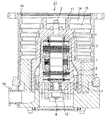
- FIG. 2 is a cross-sectional view showing a configuration of a vacuum pump provided with a magnetic bearing applied to an embodiment of the present invention.
- This vacuum pump constitutes a turbo molecular pump having a composite blade.
- the rotor shaft 2 is rotatably disposed in the central portion of the vacuum pump 21, and a DC motor 1 for rotating the rotor shaft 2 is attached to the central portion of the rotor shaft 2.
- a radial electromagnet 3 is arranged in the radial direction of the rotor shaft 2 located on the upper part of the DC motor 1 to constitute one magnetic bearing of the rotor shaft 2.
- a radial sensor 4 for detecting the displacement of the rotor shaft 2 is disposed in the vicinity of the radial electromagnet 3. *
- a radial electromagnet 5 is arranged in the radial direction of the rotor shaft 2 positioned below the DC motor 1 to constitute the other magnetic bearing of the rotor shaft 2.
- a radial sensor 6 for detecting the displacement of the rotor shaft 2 is disposed in the vicinity of the radial electromagnet 5.
- an axial electromagnet 7 is disposed in the axial direction in the vicinity of the lower end portion of the rotor shaft 2 to constitute a magnetic bearing in the axial direction of the rotor shaft 2.
- An axial sensor 8 for detecting displacement in the axial direction of the rotor shaft 2 is disposed at the lower end of the rotor shaft 2.
- protective dry bearings 11 and 12 are disposed at the upper end and lower end of the rotor shaft 2 respectively, and the rotor shaft 2 is prevented from being abnormally displaced by the oscillation of the radial magnetic bearings 4 and 5.
- a stator blade 13 is disposed on the fixed side of the vacuum pump 21, and a rotor blade 14 is rotatably disposed facing the stator blade 13.
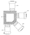
- FIG. 3 is a conceptual diagram showing a mounting posture when a vacuum pump applied to one embodiment of the present invention is mounted on a semiconductor manufacturing measure.
- the vacuum pump 21 is attached to the semiconductor manufacturing apparatus 22 in an optimal posture.
- the vacuum pump 21a is attached in the vertical direction
- the vacuum pump 21b is attached in the inclined direction
- the vacuum pump 21c is attached in the horizontal direction
- It can be attached in an inverted direction like the vacuum pump 21d.
- the weight of the rotor shaft of the magnetic bearing when mounted in the vertical direction with respect to the semiconductor manufacturing apparatus 22 as in the vacuum pump 21a, the weight of the rotor shaft of the magnetic bearing is not applied to the electromagnet side in the radial direction at all.
- the total weight of the rotor shaft of the magnetic bearing is applied to the electromagnet side in the radial direction. That is, since the vacuum pump 21 is attached to the semiconductor manufacturing apparatus 22 in various postures, the weight of the rotor shaft fluctuates due to the vector direction of gravity in the electromagnetic force of the magnetic bearing formed in the vacuum pump 21. Are added (subtracted).
- the force (unstable element) of the unstable spring constant of the electromagnet that varies depending on the mounting orientation of the magnetic bearing is extracted, and this unstable element is used as the unstable compensation gain.
- the gain command value is generated by adding the unstable compensation gain to the basic gain that is uniquely determined regardless of the mounting orientation of the magnetic bearing.
- a current command value optimum for each mounting posture is generated, and the pair of electromagnets are appropriately controlled by the generated current command value. This will be described in detail below.
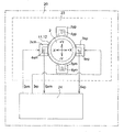
- FIG. 4 is a conceptual diagram showing a configuration of a magnetic bearing device composed of a magnetic bearing and a control device applied to one embodiment of the present invention.
- the magnetic bearing device 20 includes a magnetic bearing 23 and a control device 24.
- a pair of radial electromagnets (+ x electromagnet 3 xp and ⁇ x electromagnet 3 xm) are arranged to face each other in the x direction (+ x to ⁇ x direction) of the rotor shaft 2.
- radial sensors (+ x sensor 4xp and ⁇ x sensor 4xm) for detecting the rotor shaft displacement in the x direction are arranged in the vicinity of the radial electromagnets (+ x electromagnet 3xp and ⁇ x electromagnet 3xm), respectively.
- Displacement signals Sxp and Sxm from each radial sensor (+ x sensor 4xp and ⁇ x sensor 4xm) are fed back to the control device 24.
- Control signals (currents) Ixp and Ixm from the control device 24 are supplied to a pair of x-axis radial electromagnets (+ x electromagnet 3xp and ⁇ x electromagnet 3xm).
- the attraction forces of the + x electromagnet 3xp and the ⁇ x electromagnet 3xm are controlled by the currents Ixp and Ixm controlled by the feedback of the displacement signals Sxp and Sxm, and as a result, the rotor shaft 2 returns to the reference position (center position).
- a pair of radial electromagnets (+ y electromagnet 3 yp and ⁇ y electromagnet 3 ym) are arranged facing each other in the y direction of the rotor shaft 2.
- radial sensors (+ y sensor 4 yp and ⁇ y sensor 4 ym) for detecting the rotor shaft displacement in the y direction are arranged in the vicinity of the radial electromagnets (+ y electromagnet 3 yp and ⁇ y electromagnet 3 ym), respectively. Since FIG.
- FIG. 4 is a diagram for explaining the current in the x-axis direction, a radial electromagnet in the y direction (+ y electromagnet 3 yp and ⁇ y electromagnet 3 ym) and a radial sensor in the y direction (+ y sensor 4 yp and ⁇ y sensor 4 ym).
- the signal system is omitted for.
- the radial sensors 4xp, 4xm, 4yp, 4ym of the x-axis and y-axis seem to be fixed to the radial electromagnets 3xp, 3xm, 3yp, 3ym, respectively.
- the radial sensors (+ x sensor 4xp, ⁇ x sensor 4xm) that are displacement sensors detect the position of the rotor shaft 2 and feed back the displacement signals Sxp and Sxm to the control device 24. Then, the control device 24 performs signal processing based on the difference from the reference position stored in advance, and appropriately determines the current to be passed through the radial electromagnets (+ x electromagnet 3xp, ⁇ x electromagnet 3xm). Then, a desired current (Ixp, Ixm) is supplied from a current control amplifier (not shown) in the control device 24 to the radial electromagnets (+ x electromagnet 3xp, ⁇ x electromagnet 3xm).
- radial electromagnets (+ x electromagnet 3xp, -x electromagnet 3x m) works to return the rotor shaft 2 to the reference position (the center position of the radial direction x-axis) by a desired suction force.
- the same operation is performed for the y-axis in the radial direction, and the rotor shaft 2 is returned to the reference position (the center position of the radial y-axis).
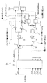
- FIG. 5 is a block diagram showing a control system of a magnetic bearing control device applied to one embodiment of the present invention. This figure shows only the control system of the control device that controls the current of the pair of electromagnets (radial electromagnets) interposed in the Xh axis in the radial direction of the rotor shaft of the magnetic bearing. *
- the control device 24 includes current control amplifiers 31xp and 31xm that individually control currents of a pair of electromagnets facing in the radial direction, and a squarer 32xp that squares current detection values from the current control amplifiers 31xp and 31xm, respectively.
- an adder 33 for adding the squared current detection values, a low-pass filter 34 for averaging the squares of the current detection values, and the square of the current detection values output from the low-pass filter 34
- a correction coefficient multiplier 35 that obtains an average value of correction gain command values by multiplying the addition value by a correction coefficient, and a gain command by adding the correction gain command value and the basic gain setting value output from the correction coefficient multiplier 35
- An adder 36 for obtaining the value G, and a force command intermediate signal having position information of the radial axis of the rotor shaft and one axis of the thrust direction are processed and output.
- a compensator 37 a gain amplifier 38 for amplifying the Xh-axis force command intermediate signal output from the compensator 37 based on the gain command value G, and a non-linear force-current command intermediate signal output from the gain amplifier 38
- Power linearizer 39 that linearizes the characteristics of the current
- an inverter 40 that branches the linearized current command intermediate signal and inverts one of the signals, a current command intermediate signal that is not inverted, and a bias current setting value. Is added to the current control amplifier 31xp, and the current command intermediate signal inverted by the inverter 40 and the bias current set value are added to obtain the current command value to control the current.
- an adder 41xm that outputs to the amplifier 31xm. *
- the current control amplifier 31xp has a function for causing an appropriate current (excitation current) to flow to one + x electromagnet 3xp (see FIG. 4) facing the radial direction of the rotor shaft.
- the current control amplifier 31xm has a function for flowing an appropriate current (excitation current) to the other -x electromagnet 3xm (see FIG. 4) facing the radial direction of the rotor shaft.
- the squarer 32xp and the squarer 32xm are respectively an electromagnet pair (+ x electromagnet 3xp and ⁇ x that attracts the rotor shaft (not shown) of the magnetic bearing in the opposite direction of the x-axis from the current control amplifier 31xp and the current control amplifier 31xm, respectively. It has a function of acquiring current detection values (Ixhp, Ixhm) of the electromagnets 3xm and squaring these current detection values (Ixhp, Ixhm).
- the adder 33 has a function of obtaining (Ixhp ⁇ 2 + Ixhm ⁇ 2) by adding the current detection values squared by the squarers 32xp and 32xm.
- the low-pass filter 34 has a function of averaging the square / addition value (Ixhp ⁇ 2 + Ixhm ⁇ 2) of the current output from the adder 33 in order to remove noise and the like. *
- the adder 36 adds the correction gain command value Kcomp output from the correction coefficient multiplier 35 and the basic gain setting value Kctrl set in advance regardless of the arrangement and orientation of the magnetic bearings, to thereby obtain a gain command value G (Kctrl + Kcomp). It has the function to ask for. *
- the compensator 37 processes position signals from the four axes Pxh, Pyh, Pxb, Pyb in the radial direction of the rotor shaft and one axis Pz in the thrust direction, and outputs a force command intermediate signal having position information of the rotor shaft. It has a function.
- the position signal Pxh is obtained from the pair of radial sensors 4xp and 4xm for detecting the relative displacement between the pair of electromagnets 3xp and 3xm in the upper X-axis (Xh-axis) direction in the 5-axis control type magnetic bearing shown in FIG. Signal.
- the position signal Pyh is obtained from a pair of radial sensors 4yp and 4ym that detect a relative positional shift between the pair of electromagnets 3yp and 3ym in the upper Y-axis (Yh-axis) direction in the 5-axis control type magnetic bearing shown in FIG. Signal.
- the position signal Pxb is a pair of radial sensors 6xp for detecting the relative displacement between the pair of electromagnets 5xp and 5xm in the lower X-axis (Xb-axis) direction in the 5-axis control type magnetic bearing shown in FIG.
- the position signal Pyb is a signal of a pair of radial sensors 6 yp and 6 ym that detects a relative positional shift between the pair of electromagnets 5 yp and 5 ym in the lower Y-axis (Yb-axis) direction.
- the position signal Pz is a signal from the axial sensor 8z that detects a relative positional shift (a positional shift in the thrust direction) of the axial electromagnets 7zm and 7zp arranged in the Z-axis direction in a pair of upper and lower. Displaying the processing systems for the position signals of all the five axes makes the diagram of the signal processing system complicated. Therefore, in FIG. 5, only the signal processing system for only the position signal Pxh is displayed.
- the gain amplifier 38 receives the Xh-axis force command intermediate signal generated and output by the compensator 37, and outputs the Xh-axis based on the gain command value G (Kctrl + Kcomp) output and set from the adder 36. A function of amplifying the force command intermediate signal is provided. *
- the force / current linearizer 39 has a function of linearizing the non-linear current command intermediate signal (force-current characteristic signal) output from the gain amplifier 38 based on the bias current setting value.
- the force / current linearizer 39 detects the bias current set value and switches the circuit only when current does not exist in both the pair of electromagnets 5xp and 5xm, thereby enabling the linearization function.
- the inverter 40 has a function of inverting one of the signals branched from the linear current command intermediate signal output from the force-current linearizer 39.
- the adder 41xp has a function of obtaining a current command value Cxhp by adding the non-inverted current command intermediate signal and the bias current set value OCh, and outputting the current command value Cxhp to the current control amplifier 31xp.
- the adder 41xm has a function of adding the current command intermediate signal inverted by the inverter 40 and the bias current set value OCh to obtain a current command value Cxhm and outputting the current command value Cxhm to the current control amplifier 31xm. ing. *
- current detection values (Ixhp, Ixhm) of a pair of electromagnets (+ x electromagnet 3xp and ⁇ x electromagnet 3xm) that pull the rotor shafts in opposite directions are obtained from current control amplifiers 31xp, 31xm, respectively, and a squarer 32xp 32xm and the adder 33 are used to calculate the sum of squares of the current detection values (Ixhp ⁇ 2 + Ixhm ⁇ 2).
- the correction coefficient calculator 35 multiplies (Ixhp ⁇ 2 + Ixhm ⁇ 2) by the correction coefficient Kcd to instability of the magnetic bearing
- the bias current command values (Cxhp, Cxhm) may be input to the squarers 32xp, 32xm instead of the current detection values (Ixhp, Ixhm).
- the low-pass filter 34 is not used, the basic operation is not hindered, but it is desirable to use the low-pass filter 34 in order to prevent noise disturbance caused by the rotation of the rotor shaft of the magnetic bearing.
- the adder 36 adds the correction gain command value Kcomp obtained by the correction coefficient calculator 35 and the basic gain Kctrl that is uniquely determined regardless of the arrangement and orientation of the magnetic bearings, thereby obtaining a gain command value G (Kctrl + Kcomp).
- the gain command value G (Kctrl + Kcomp) is set in the gain amplifier 38.
- the compensator 37 processes the position signals of the rotor shafts from Pxh, Pyh, Pxb, and Pyb of the four axes in the radial direction, respectively, and generates a force command intermediate signal for each axis.
- a case where the compensator 37 generates an Xh-axis force command intermediate signal will be described.
- the Xh-axis force command intermediate signal generated by the compensator 37 is input to the gain amplifier 38 in which the gain command value G (Kctrl + Kcomp) is set.
- the gain amplifier 38 amplifies the force command intermediate signal of the Xh axis based on the gain command value G (Kctrl + Kcomp) obtained by correcting the unstable spring constant with respect to the basic gain Kctrl based on the arrangement posture of the magnetic bearing. And output.
- the force-current linearizer 39 detects the bias current set value OCh and switches the circuit only when current is present to validate the linearization function.
- the force-current linearizer 39 may not be used, but in this case, the current correction control performance deteriorates.
- the force command intermediate signal output from the force-one-current linearizer 39 is branched, one signal is left as it is, and the other signal is inverted by the inverter 40. This is because currents of opposite polarities are supplied to a pair of radial electromagnets (+ x electromagnet 3xp and ⁇ x electromagnet 3xm) that are opposed to both sides of the Xh axis in the radial direction of the rotor shaft.
- one force command intermediate signal of the branch signal output from the force-one-current linearizer 39 is directly added to the bias current set value OCh by the adder 41xp and is generated as a current command value Cxhp, and the other force of the branch signal is generated.
- the command intermediate signal is inverted by the inverter 40 and then added to the bias current set value OCh by the adder 41xm to be generated as a current command value Cxhm.
- current command values (Cxhp, Cxhm) of electromagnet pairs (+ x electromagnet 3xp and -x electromagnet 3xm) attracting in opposite directions in the radial direction are generated, and these current command values (Cxhp, Cxhm) are respectively represented as currents. It is input to the control amplifiers 31xp and 31xm. *
- a current in which the unstable spring constant based on the arrangement orientation of the magnetic bearing is corrected flows from the current control amplifier 31xp to the radial electromagnet (+ x electromagnet 3xp) arranged on one of the Xh axes in the radial direction.
- a current whose unstable spring constant is corrected based on the arrangement posture of the magnetic bearing flows to a radial electromagnet ( ⁇ x electromagnet 3xm) arranged on the other side of the Xh axis in the radial direction.
- the gain command value G (Kctrl + Kcomp) set in the gain amplifier 38 becomes a small value, and the current of the magnetic bearing is controlled with a low gain.
- the gain command value G (Kctrl + Kcomp) set in the gain amplifier 38 becomes a large value, and the magnetic bearing is controlled by the current command value amplified with a high gain.
- the magnetic bearing can ensure proper rigidity without lowering the rigidity.
- the current correction function in the control device shown in FIG. 5 can be arbitrarily canceled when adjusting the magnetic bearing device.
- the displacement signal Sxp by the radial sensor (+ x sensor 4xp, ⁇ x sensor 4xm) This is a control function only for feedback of Sxm.
- the first term is the current electromagnet force
- the second term is the spring force that the magnetic bearing pulls back around the rotor shaft
- the term is the force of the unstable spring constant of the magnetic bearing
- the fourth term is the force for correcting the displacement of the rotor shaft.
- the total attractive force (F) in a moment after the pair of opposing electromagnets is the current total of the pair of electromagnets. Only the spring force (Gctrl ⁇ ⁇ ) that pulls the rotor shaft back to the center of the magnetic bearing is applied to the attractive force (F0), and the attractive force due to the unstable spring constant of the magnetic bearing is canceled out. That is, only a force that pulls the rotor shaft back to the center of the magnetic bearing acts on the pair of opposing electromagnets.
- the current acquisition unit corresponds to the two squarers 32xp and 32xm and the adder 33.
- the correction coefficient calculator corresponds to the correction coefficient calculator 35.
- the first adding means corresponds to the adder 36.
- the current control means corresponds to the gain amplifier 38, the inverter 40, the adders 41xp and 41xm, and the current control amplifiers 31xp and 31xm.
- the squaring means corresponds to the squarers 32xp and 32xm.
- the second adding means corresponds to the adder 33.
- the linear means corresponds to the force-current linearizer 39.
- the control function 24 may be realized by an electronic component (discrete) using an operational amplifier or the like, or may be realized by software using a microcomputer, a DSP (Digital Signal Processor), or the like. *
- the magnetic bearing device of the present invention is non-contact support, non-lubricated, and capable of ultra-high speed rotation with low vibration, it is not limited to a vacuum pump, and is not limited to a centrifugal compressor, turbine generator, turbo expander, grinding spindle, blood It can also be used effectively for flow pumps, semiconductor manufacturing equipment, measurement / analysis equipment, and the like.
Landscapes
- Engineering & Computer Science (AREA)
- General Engineering & Computer Science (AREA)
- Mechanical Engineering (AREA)
- Physics & Mathematics (AREA)
- Electromagnetism (AREA)
- Power Engineering (AREA)
- Magnetic Bearings And Hydrostatic Bearings (AREA)
- Non-Positive Displacement Air Blowers (AREA)
Abstract
Description
m)は所望の吸引力によってロータ軸2を基準位置(ラジアル方向x軸の中心位置)へ復帰させるように働く。ラジアル方向のy軸についても同様の動作を行い、ロータ軸2を基準位置(ラジアル方向y軸の中心位置)へ復帰させるように働く。
Sxmのフィードバックのみの制御機能となる。
Claims (10)
- 電磁石の電磁力によってロータ軸を非接触で支持する磁気軸受と、該磁気軸受を制御する制御機器と、を備えた磁気軸受装置であって、 前記制御機器は、 前記磁気軸受の前記ロータ軸を反対方向に引き合う一対の前記電磁石の各々に流れる電流定常値を取得する電流取得手段と、 前記電流定常値から、前記磁気軸受の取付姿勢に起因して生じる一対の前記電磁石の吸引力による不安定ばね定数を補償する補正ゲイン指令値を求める補正係数演算手段と、 前記補正ゲイン指令値と前記磁気軸受の取付姿勢によらず一義的に決まる基本ゲインとを加算してゲイン指令値を求める第1の加算手段と、 前記ゲイン指令値に基づいて生成された電流指令値により、一対の前記電磁石の各々に流れる電流を制御する電流制御手段と、 を備えていることを特徴とする磁気軸受装置。
- 前記電流取得手段は、一対の前記電磁石の各々に流れる電流の電流検出値、又は、前記電流指令値に基づいて、前記電流定常値を取得することを特徴とする請求項1記載の磁気軸受装置。
- 前記電流制御手段は、前記ロータ軸の位置情報を有する力指令中間信号を前記ゲイン指令値によって制御し、前記ゲイン指令値によって制御された前記力指令中間信号とバイアス電流設定値とを加算して前記電流指令値を生成することを特徴とする請求項1又は2記載の磁気軸受装置。
- 前記電流指令値は、一対の前記電磁石に対して、前記不安定ばね定数を打ち消し、前記ロータ軸を前記磁気軸受の中心に引き戻す力のみを作用させることを特徴とする請求項1乃至3の何れか1項記載の磁気軸受装置。
- 前記電流取得手段は、 一対の前記電磁石の各々に流れる前記電流定常値を個別に二乗化する一対の二乗化手段と、 一対の前記二乗化手段が個別に二乗化した各々の電流定常値を加算する第2の加算手段と、 を備えていることを特徴とする請求項1乃至4の何れか1項記載の磁気軸受装置。
- 一対の前記二乗化手段と前記第2の加算手段とにより二乗・加算された電流定常値を平均化処理して前記補正係数演算手段に引き渡すローパスフィルタをさらに備えていることを特徴とする請求項5記載の磁気軸受装置。
- 前記ローパスフィルタは、共振周波数が略1Hzであることを特徴とする請求項6記載の磁気軸受装置。
- 前記電流制御手段が生成した電流指令値と前記電磁石の吸引力との関係を示す非線形特性を前記バイアス電流設定値により線形化する線形化手段をさらに備えていることを特徴とする請求項3乃至7の何れか1項記載の磁気軸受装置。
- 前記線形化手段は、一対の前記電磁石の両方に電流が流れていないときのみ機能することを特徴とする請求項8記載の磁気軸受装置。
- 請求項1乃至9の何れか1項記載の磁気軸受装置を備えていることを特徴とする真空ポンプ。
Priority Applications (4)
| Application Number | Priority Date | Filing Date | Title |
|---|---|---|---|
| CN201480064003.XA CN105723107B (zh) | 2013-11-29 | 2014-10-03 | 磁力轴承装置、以及真空泵 |
| EP14865812.3A EP3076036B1 (en) | 2013-11-29 | 2014-10-03 | Magnetic bearing device and vacuum pump |
| KR1020167012128A KR102213999B1 (ko) | 2013-11-29 | 2014-10-03 | 자기 베어링 장치, 및 진공 펌프 |
| US15/037,071 US10359046B2 (en) | 2013-11-29 | 2014-10-03 | Magnetic bearing device and vacuum pump |
Applications Claiming Priority (2)
| Application Number | Priority Date | Filing Date | Title |
|---|---|---|---|
| JP2013-246961 | 2013-11-29 | ||
| JP2013246961A JP6321949B2 (ja) | 2013-11-29 | 2013-11-29 | 磁気軸受装置、及び真空ポンプ |
Publications (1)
| Publication Number | Publication Date |
|---|---|
| WO2015079802A1 true WO2015079802A1 (ja) | 2015-06-04 |
Family
ID=53198756
Family Applications (1)
| Application Number | Title | Priority Date | Filing Date |
|---|---|---|---|
| PCT/JP2014/076500 Ceased WO2015079802A1 (ja) | 2013-11-29 | 2014-10-03 | 磁気軸受装置、及び真空ポンプ |
Country Status (6)
| Country | Link |
|---|---|
| US (1) | US10359046B2 (ja) |
| EP (1) | EP3076036B1 (ja) |
| JP (1) | JP6321949B2 (ja) |
| KR (1) | KR102213999B1 (ja) |
| CN (1) | CN105723107B (ja) |
| WO (1) | WO2015079802A1 (ja) |
Families Citing this family (7)
| Publication number | Priority date | Publication date | Assignee | Title |
|---|---|---|---|---|
| EP3372854B1 (en) * | 2015-12-10 | 2020-06-24 | Daikin Industries, Ltd. | Magnetic bearing device and compressor |
| JP7148230B2 (ja) * | 2017-08-31 | 2022-10-05 | エドワーズ株式会社 | 真空ポンプ及び制御装置 |
| EP3489518B1 (de) * | 2017-11-28 | 2020-02-12 | Pfeiffer Vacuum Gmbh | Vakuumpumpe sowie anordnung und verfahren zur handhabung und/oder montage einer vakuumpumpe |
| CN109707733B (zh) * | 2018-11-27 | 2020-05-22 | 清华大学 | 一种磁轴承隔振与抗冲击控制方法及系统 |
| FR3129722B1 (fr) * | 2021-11-26 | 2023-11-24 | Skf Magnetic Mechatronics | Dispositif d’estimation de la sensibilié d’un capteur, procédé et système associé |
| JP2024168908A (ja) * | 2023-05-25 | 2024-12-05 | エドワーズ株式会社 | 真空ポンプ、磁気軸受装置及びロータ |
| US20250271002A1 (en) * | 2024-02-28 | 2025-08-28 | Kla Corporation | Three-axis tuned mass damper for turbo molecular pump |
Citations (5)
| Publication number | Priority date | Publication date | Assignee | Title |
|---|---|---|---|---|
| JPS6483916A (en) * | 1987-09-28 | 1989-03-29 | Hitachi Ltd | Control type magnetic bearing device |
| JPH02134410A (ja) * | 1988-11-12 | 1990-05-23 | Toshiba Corp | 磁気軸受の制御装置 |
| JPH0484915U (ja) * | 1990-11-30 | 1992-07-23 | ||
| JPH0942290A (ja) | 1995-07-24 | 1997-02-10 | Shimadzu Corp | 磁気軸受装置 |
| JP2006083924A (ja) * | 2004-09-15 | 2006-03-30 | Boc Edwards Kk | 磁気軸受制御装置 |
Family Cites Families (9)
| Publication number | Priority date | Publication date | Assignee | Title |
|---|---|---|---|---|
| US5256637A (en) * | 1991-07-22 | 1993-10-26 | Mechanical Technology Inc. | Superconducting coil bearings for rotor load |
| JPH05141423A (ja) * | 1991-11-18 | 1993-06-08 | Mitsubishi Heavy Ind Ltd | 可動物体装着用磁気軸受装置 |
| JP2835942B2 (ja) * | 1995-10-27 | 1998-12-14 | セイコー精機株式会社 | 磁気軸受の制御装置 |
| US6700258B2 (en) * | 2001-05-23 | 2004-03-02 | Calnetix | Magnetic thrust bearing with permanent bias flux |
| JP4017383B2 (ja) * | 2001-12-04 | 2007-12-05 | Bocエドワーズ株式会社 | 磁気軸受制御装置 |
| JP2004132441A (ja) * | 2002-10-09 | 2004-04-30 | Ntn Corp | 磁気軸受装置、それを用いたエキシマレーザ用貫流ファン装置、磁気軸受のフィードバック制御をコンピュータに実行させるためのプログラム、および磁気軸受のフィードバック制御をコンピュータに実行させるためのプログラムを記録したコンピュータ読み取り可能な記録媒体 |
| EP1942283B1 (en) * | 2005-07-05 | 2016-10-26 | Ebara Corporation | Magnetic bearing device and method of operating the device |
| CN1315254C (zh) * | 2005-07-08 | 2007-05-09 | 北京航空航天大学 | 一种集成化磁悬浮飞轮磁轴承数字控制装置 |
| JP5279890B2 (ja) * | 2011-12-29 | 2013-09-04 | 株式会社大阪真空機器製作所 | ラジアル方向制御器及び、それが適用された磁気軸受装置 |
-
2013
- 2013-11-29 JP JP2013246961A patent/JP6321949B2/ja active Active
-
2014
- 2014-10-03 EP EP14865812.3A patent/EP3076036B1/en active Active
- 2014-10-03 US US15/037,071 patent/US10359046B2/en active Active
- 2014-10-03 WO PCT/JP2014/076500 patent/WO2015079802A1/ja not_active Ceased
- 2014-10-03 CN CN201480064003.XA patent/CN105723107B/zh active Active
- 2014-10-03 KR KR1020167012128A patent/KR102213999B1/ko active Active
Patent Citations (5)
| Publication number | Priority date | Publication date | Assignee | Title |
|---|---|---|---|---|
| JPS6483916A (en) * | 1987-09-28 | 1989-03-29 | Hitachi Ltd | Control type magnetic bearing device |
| JPH02134410A (ja) * | 1988-11-12 | 1990-05-23 | Toshiba Corp | 磁気軸受の制御装置 |
| JPH0484915U (ja) * | 1990-11-30 | 1992-07-23 | ||
| JPH0942290A (ja) | 1995-07-24 | 1997-02-10 | Shimadzu Corp | 磁気軸受装置 |
| JP2006083924A (ja) * | 2004-09-15 | 2006-03-30 | Boc Edwards Kk | 磁気軸受制御装置 |
Non-Patent Citations (1)
| Title |
|---|
| See also references of EP3076036A4 * |
Also Published As
| Publication number | Publication date |
|---|---|
| EP3076036A4 (en) | 2017-07-12 |
| EP3076036B1 (en) | 2020-08-12 |
| US20160290351A1 (en) | 2016-10-06 |
| CN105723107A (zh) | 2016-06-29 |
| KR20160092995A (ko) | 2016-08-05 |
| EP3076036A1 (en) | 2016-10-05 |
| JP2015105680A (ja) | 2015-06-08 |
| JP6321949B2 (ja) | 2018-05-09 |
| KR102213999B1 (ko) | 2021-02-08 |
| US10359046B2 (en) | 2019-07-23 |
| CN105723107B (zh) | 2019-06-18 |
Similar Documents
| Publication | Publication Date | Title |
|---|---|---|
| JP6321949B2 (ja) | 磁気軸受装置、及び真空ポンプ | |
| JP4287213B2 (ja) | 振動抑制機能を有する磁気軸受装置、振動推定機能を有する磁気軸受装置及び該磁気軸受装置を搭載したポンプ装置 | |
| KR100622098B1 (ko) | 제어형 자기 베어링장치 | |
| US10968949B2 (en) | Magnetic bearing control device and vacuum pump | |
| JP6695541B2 (ja) | 磁気軸受制御装置および真空ポンプ | |
| Zad et al. | Design and analysis of a novel bearingless motor for a miniature axial flow blood pump | |
| Zheng et al. | Rotor balancing for magnetically levitated TMPs integrated with vibration self-sensing of magnetic bearings | |
| CN108716471A (zh) | 一种磁悬浮分子泵转子极小位移主动控制方法 | |
| CN108106611B (zh) | 一种基于多重相移准谐振控制的磁悬浮转子谐波电流抑制方法 | |
| CN104333289A (zh) | 改进的主动磁轴承控制系统 | |
| US8853905B2 (en) | Radial direction controller and magnetic bearing apparatus utilizing same | |
| JP7447546B2 (ja) | 磁気軸受装置および真空ポンプ | |
| CN107104618B (zh) | 一种磁悬浮电机转子的控制方法及系统 | |
| JP6269080B2 (ja) | 磁気軸受装置および真空ポンプ | |
| JP6801481B2 (ja) | 磁気軸受装置および真空ポンプ | |
| Sahinkaya et al. | Bias current optimization and fuzzy controllers for magnetic bearings in turbo molecular pumps | |
| JP2957222B2 (ja) | 能動軸受のロータ支持制御装置 | |
| JP2002081444A (ja) | 磁気軸受装置および磁気軸受装置のセンサ感度調整方法 | |
| Cheng et al. | Design and control of hybrid magnetic bearings for maglev axial flow blood pump | |
| JP5115105B2 (ja) | 磁気軸受システム | |
| 张钢 | Dynamic characteristics of a working platform supported by an AMG | |
| JP2002310153A (ja) | 磁気軸受を有する回転機 | |
| CN103425051B (zh) | 一种磁悬浮旋转机械的不平衡量辨识与振动抑制控制系统 |
Legal Events
| Date | Code | Title | Description |
|---|---|---|---|
| 121 | Ep: the epo has been informed by wipo that ep was designated in this application |
Ref document number: 14865812 Country of ref document: EP Kind code of ref document: A1 |
|
| ENP | Entry into the national phase |
Ref document number: 20167012128 Country of ref document: KR Kind code of ref document: A |
|
| WWE | Wipo information: entry into national phase |
Ref document number: 15037071 Country of ref document: US |
|
| REEP | Request for entry into the european phase |
Ref document number: 2014865812 Country of ref document: EP |
|
| WWE | Wipo information: entry into national phase |
Ref document number: 2014865812 Country of ref document: EP |
|
| NENP | Non-entry into the national phase |
Ref country code: DE |