WO2015080270A1 - 点火装置 - Google Patents
点火装置 Download PDFInfo
- Publication number
- WO2015080270A1 WO2015080270A1 PCT/JP2014/081641 JP2014081641W WO2015080270A1 WO 2015080270 A1 WO2015080270 A1 WO 2015080270A1 JP 2014081641 W JP2014081641 W JP 2014081641W WO 2015080270 A1 WO2015080270 A1 WO 2015080270A1
- Authority
- WO
- WIPO (PCT)
- Prior art keywords
- secondary current
- discharge
- ignition
- current
- voltage
- Prior art date
- Legal status (The legal status is an assumption and is not a legal conclusion. Google has not performed a legal analysis and makes no representation as to the accuracy of the status listed.)
- Ceased
Links
Images








Classifications
-
- F—MECHANICAL ENGINEERING; LIGHTING; HEATING; WEAPONS; BLASTING
- F02—COMBUSTION ENGINES; HOT-GAS OR COMBUSTION-PRODUCT ENGINE PLANTS
- F02P—IGNITION, OTHER THAN COMPRESSION IGNITION, FOR INTERNAL-COMBUSTION ENGINES; TESTING OF IGNITION TIMING IN COMPRESSION-IGNITION ENGINES
- F02P15/00—Electric spark ignition having characteristics not provided for in, or of interest apart from, groups F02P1/00 - F02P13/00 and combined with layout of ignition circuits
- F02P15/10—Electric spark ignition having characteristics not provided for in, or of interest apart from, groups F02P1/00 - F02P13/00 and combined with layout of ignition circuits having continuous electric sparks
-
- F—MECHANICAL ENGINEERING; LIGHTING; HEATING; WEAPONS; BLASTING
- F02—COMBUSTION ENGINES; HOT-GAS OR COMBUSTION-PRODUCT ENGINE PLANTS
- F02P—IGNITION, OTHER THAN COMPRESSION IGNITION, FOR INTERNAL-COMBUSTION ENGINES; TESTING OF IGNITION TIMING IN COMPRESSION-IGNITION ENGINES
- F02P3/00—Other installations
- F02P3/02—Other installations having inductive energy storage, e.g. arrangements of induction coils
- F02P3/04—Layout of circuits
- F02P3/05—Layout of circuits for control of the magnitude of the current in the ignition coil
- F02P3/051—Opening or closing the primary coil circuit with semiconductor devices
-
- F—MECHANICAL ENGINEERING; LIGHTING; HEATING; WEAPONS; BLASTING
- F02—COMBUSTION ENGINES; HOT-GAS OR COMBUSTION-PRODUCT ENGINE PLANTS
- F02P—IGNITION, OTHER THAN COMPRESSION IGNITION, FOR INTERNAL-COMBUSTION ENGINES; TESTING OF IGNITION TIMING IN COMPRESSION-IGNITION ENGINES
- F02P17/00—Testing of ignition installations, e.g. in combination with adjusting; Testing of ignition timing in compression-ignition engines
- F02P17/12—Testing characteristics of the spark, ignition voltage or current
-
- F—MECHANICAL ENGINEERING; LIGHTING; HEATING; WEAPONS; BLASTING
- F02—COMBUSTION ENGINES; HOT-GAS OR COMBUSTION-PRODUCT ENGINE PLANTS
- F02P—IGNITION, OTHER THAN COMPRESSION IGNITION, FOR INTERNAL-COMBUSTION ENGINES; TESTING OF IGNITION TIMING IN COMPRESSION-IGNITION ENGINES
- F02P3/00—Other installations
- F02P3/02—Other installations having inductive energy storage, e.g. arrangements of induction coils
- F02P3/04—Layout of circuits
- F02P3/0407—Opening or closing the primary coil circuit with electronic switching means
-
- F—MECHANICAL ENGINEERING; LIGHTING; HEATING; WEAPONS; BLASTING
- F02—COMBUSTION ENGINES; HOT-GAS OR COMBUSTION-PRODUCT ENGINE PLANTS
- F02P—IGNITION, OTHER THAN COMPRESSION IGNITION, FOR INTERNAL-COMBUSTION ENGINES; TESTING OF IGNITION TIMING IN COMPRESSION-IGNITION ENGINES
- F02P3/00—Other installations
- F02P3/02—Other installations having inductive energy storage, e.g. arrangements of induction coils
- F02P3/04—Layout of circuits
- F02P3/0407—Opening or closing the primary coil circuit with electronic switching means
- F02P3/0435—Opening or closing the primary coil circuit with electronic switching means with semiconductor devices
- F02P3/0442—Opening or closing the primary coil circuit with electronic switching means with semiconductor devices using digital techniques
-
- F—MECHANICAL ENGINEERING; LIGHTING; HEATING; WEAPONS; BLASTING
- F02—COMBUSTION ENGINES; HOT-GAS OR COMBUSTION-PRODUCT ENGINE PLANTS
- F02P—IGNITION, OTHER THAN COMPRESSION IGNITION, FOR INTERNAL-COMBUSTION ENGINES; TESTING OF IGNITION TIMING IN COMPRESSION-IGNITION ENGINES
- F02P3/00—Other installations
- F02P3/02—Other installations having inductive energy storage, e.g. arrangements of induction coils
- F02P3/04—Layout of circuits
- F02P3/05—Layout of circuits for control of the magnitude of the current in the ignition coil
-
- F—MECHANICAL ENGINEERING; LIGHTING; HEATING; WEAPONS; BLASTING
- F02—COMBUSTION ENGINES; HOT-GAS OR COMBUSTION-PRODUCT ENGINE PLANTS
- F02P—IGNITION, OTHER THAN COMPRESSION IGNITION, FOR INTERNAL-COMBUSTION ENGINES; TESTING OF IGNITION TIMING IN COMPRESSION-IGNITION ENGINES
- F02P3/00—Other installations
- F02P3/06—Other installations having capacitive energy storage
- F02P3/08—Layout of circuits
- F02P3/0876—Layout of circuits the storage capacitor being charged by means of an energy converter (DC-DC converter) or of an intermediate storage inductance
- F02P3/0884—Closing the discharge circuit of the storage capacitor with semiconductor devices
- F02P3/0892—Closing the discharge circuit of the storage capacitor with semiconductor devices using digital techniques
-
- F—MECHANICAL ENGINEERING; LIGHTING; HEATING; WEAPONS; BLASTING
- F02—COMBUSTION ENGINES; HOT-GAS OR COMBUSTION-PRODUCT ENGINE PLANTS
- F02P—IGNITION, OTHER THAN COMPRESSION IGNITION, FOR INTERNAL-COMBUSTION ENGINES; TESTING OF IGNITION TIMING IN COMPRESSION-IGNITION ENGINES
- F02P5/00—Advancing or retarding ignition; Control therefor
- F02P5/04—Advancing or retarding ignition; Control therefor automatically, as a function of the working conditions of the engine or vehicle or of the atmospheric conditions
- F02P5/145—Advancing or retarding ignition; Control therefor automatically, as a function of the working conditions of the engine or vehicle or of the atmospheric conditions using electrical means
-
- F—MECHANICAL ENGINEERING; LIGHTING; HEATING; WEAPONS; BLASTING
- F02—COMBUSTION ENGINES; HOT-GAS OR COMBUSTION-PRODUCT ENGINE PLANTS
- F02P—IGNITION, OTHER THAN COMPRESSION IGNITION, FOR INTERNAL-COMBUSTION ENGINES; TESTING OF IGNITION TIMING IN COMPRESSION-IGNITION ENGINES
- F02P5/00—Advancing or retarding ignition; Control therefor
- F02P5/04—Advancing or retarding ignition; Control therefor automatically, as a function of the working conditions of the engine or vehicle or of the atmospheric conditions
- F02P5/145—Advancing or retarding ignition; Control therefor automatically, as a function of the working conditions of the engine or vehicle or of the atmospheric conditions using electrical means
- F02P5/15—Digital data processing
-
- F—MECHANICAL ENGINEERING; LIGHTING; HEATING; WEAPONS; BLASTING
- F02—COMBUSTION ENGINES; HOT-GAS OR COMBUSTION-PRODUCT ENGINE PLANTS
- F02P—IGNITION, OTHER THAN COMPRESSION IGNITION, FOR INTERNAL-COMBUSTION ENGINES; TESTING OF IGNITION TIMING IN COMPRESSION-IGNITION ENGINES
- F02P9/00—Electric spark ignition control, not otherwise provided for
- F02P9/002—Control of spark intensity, intensifying, lengthening, suppression
- F02P9/007—Control of spark intensity, intensifying, lengthening, suppression by supplementary electrical discharge in the pre-ionised electrode interspace of the sparking plug, e.g. plasma jet ignition
-
- F—MECHANICAL ENGINEERING; LIGHTING; HEATING; WEAPONS; BLASTING
- F02—COMBUSTION ENGINES; HOT-GAS OR COMBUSTION-PRODUCT ENGINE PLANTS
- F02P—IGNITION, OTHER THAN COMPRESSION IGNITION, FOR INTERNAL-COMBUSTION ENGINES; TESTING OF IGNITION TIMING IN COMPRESSION-IGNITION ENGINES
- F02P9/00—Electric spark ignition control, not otherwise provided for
- F02P9/002—Control of spark intensity, intensifying, lengthening, suppression
-
- Y—GENERAL TAGGING OF NEW TECHNOLOGICAL DEVELOPMENTS; GENERAL TAGGING OF CROSS-SECTIONAL TECHNOLOGIES SPANNING OVER SEVERAL SECTIONS OF THE IPC; TECHNICAL SUBJECTS COVERED BY FORMER USPC CROSS-REFERENCE ART COLLECTIONS [XRACs] AND DIGESTS
- Y02—TECHNOLOGIES OR APPLICATIONS FOR MITIGATION OR ADAPTATION AGAINST CLIMATE CHANGE
- Y02T—CLIMATE CHANGE MITIGATION TECHNOLOGIES RELATED TO TRANSPORTATION
- Y02T10/00—Road transport of goods or passengers
- Y02T10/10—Internal combustion engine [ICE] based vehicles
- Y02T10/40—Engine management systems
Definitions
- the present invention relates to an ignition device for igniting an internal combustion engine, and more particularly to an ignition device provided with an auxiliary power source for maintaining discharge.
- Patent Document 1 discloses an ignition device including a DC-DC converter that injects discharge energy into the secondary side of an ignition coil in addition to a normal ignition device.
- power is supplied to the spark plug through the secondary coil of the ignition coil, thereby extending the discharge duration after the start of discharge and trying to achieve stable ignition.
- Patent Document 2 discloses, as a spark plug for an internal combustion engine, a first series connection circuit including an ignition coil (Tr), a first switching means (T1) and a second switching means (T2), And a full bridge circuit constituted by a second series connection circuit composed of the third switching means (T3) and the fourth switching means (T4).
- the center tap (1) of the first series connection circuit is connected to a power supply potential
- the center tap (2) of the second series connection circuit is connected to a reference potential
- the first and second centers are connected.
- Each tap is connected to the primary side of the ignition coil.
- a fifth switching means (T5) connected to the second center tap and the diode (D1) and a capacitor (Cz) are provided.
- An ignition device is disclosed in which the control device (SE) controls the switching means to cause dielectric breakdown, and subsequently generates an alternating current having a constant amplitude on the secondary side.
- the present invention suppresses consumption of the electrode due to re-discharge and suppresses stable discharge by superimposing a discharge current with the same polarity while preventing discharge blow-off with a simple configuration. It is an object of the present invention to provide an ignition device for an internal combustion engine that is improved in ignition robustness by maintaining.
- the ignition device is connected to at least a DC power source, an ignition coil having a primary side coil and a secondary side coil electrically connected to the DC power source, and the secondary side coil, A spark plug that generates a spark discharge in a combustion chamber of an internal combustion engine by applying a secondary voltage from the secondary coil, and a spark discharge from the spark plug is started and superimposed on the downstream side of the primary coil.
- An auxiliary power source for supplying electric energy to the power source, a first switch for switching supply and stop of energy from the auxiliary power source, and a secondary current flowing in the secondary coil during a discharge period from the ignition coil.
- a secondary current detecting means and a secondary current feedback control circuit for driving the first switch to open and close based on the secondary current detected by the secondary current detecting means.
- a secondary current feedback control means which comprises carrying out the energy charge from the auxiliary power supply without changing the polarity of the secondary current.
- the secondary current flowing in the secondary coil of the ignition coil is detected, and this is fed back to control the supply and stop of the discharge energy from the auxiliary power supply, thereby making it extremely simple.
- it is configured, it is possible to supply discharge energy to the spark plug without excess or deficiency without being affected by an increase in secondary voltage, individual differences of devices, aging deterioration, change in discharge environment, etc. Can be maintained within a certain range without interruption, and the discharge from the auxiliary power source that is performed after the spark discharge can be maintained for an arbitrary period of time, so that the ignition can be stabilized.
- a high ignition device can be realized.
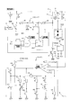
- summary of the ignition device 7 in the 1st Embodiment of this invention The block diagram which shows the outline
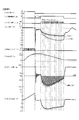
- operation of the ignition device 7 in the Example of FIG. The time chart which shows the action
- the schematic diagram which shows the method of reflecting the learning effect of the modification of a secondary current learning means Characteristics diagram for explaining another modification of secondary current learning means The schematic diagram which shows the method of reflecting the learning effect of the other modification of a secondary current learning means
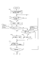
- the flowchart which shows an example of the abnormality determination method used for the ignition device 7e of FIG. FIG. 14 shows the effect of the auxiliary power supply abnormality determination means provided in the ignition device 7e of FIG. 14 shows the effect of the abnormality determining means provided in the ignition device 7e of FIG. 14, and is a time chart when it is determined that the auxiliary power source 5d is abnormal when discharging from the auxiliary power source 5d 14 shows the effect of the abnormality determining means provided in the ignition device 7e of FIG. 14, and is a time chart when it is determined that the ignition coil or the ignition switch is abnormal when discharging from the auxiliary power source 5d 14 shows the effect of the abnormality determination means provided in the ignition device 7e of FIG.
- the ignition device 7 of the present invention is provided for each cylinder of the internal combustion engine 9 and performs ignition by generating a spark discharge in a mixture of fuel and air introduced into a combustion chamber (not shown).
- the ignition device 7 includes a DC power source 1, an ignition coil 2, an ignition plug 3, an ignition switch 4, an auxiliary power source 5, and secondary current feedback control means 6 that is a main part in the present embodiment. Yes.
- the ignition device 7 in the present embodiment is characterized in that a secondary current detection means 60 and a secondary current feedback control circuit 61 are provided as the secondary current feedback control means 6.
- the secondary current detection means 60 detects the secondary current I 2 flowing through the secondary coil 21 of the ignition coil 2.
- the secondary current feedback control circuit 61 determines the threshold value of the detected secondary current I 2 and controls the supply and stop of discharge energy from the auxiliary power source 5 without switching the polarity of the secondary current I 2 . maintaining the secondary current I 2 in a predetermined range. That is, the secondary current feedback control circuit 61 maintains the secondary current I 2 in the same polarity range, preferably maintains the absolute value of the secondary current I 2 in a range equal to or greater than the blow-off limit current Ith described later.
- the secondary current feedback control means 6 controls discharge of the discharge energy from the auxiliary power source 5 without excess or deficiency regardless of the operation state of the internal combustion engine 9, so that stable discharge is always maintained and combustion is performed.
- the air-fuel mixture introduced into the room can be ignited.
- the present invention by being continuously maintained in a certain range without switching the polarity of the secondary current I 2, since the energy supply to the air-fuel mixture is continuously performed, 0 of the secondary current I 2 It is possible to prevent blow-out due to a drop to the vicinity of the cross and blow-off by switching the polarity of the secondary current I 2 .
- the DC power source 1 is a DC stabilized power source in which a battery or an AC power source is stabilized by a switching regulator or the like, and supplies a constant DC voltage + B such as 14 V or 24 V, for example. Further, as the DC power source 1, a battery voltage boosted by a DC-DC converter or the like can be used.
- the ignition coil 2 includes a primary side coil 20, a secondary side coil 21, and a rectifying element 22, and constitutes a known step-up transformer.
- the ignition coil 2 generates a high voltage in the secondary coil 21 when the current of the primary coil 20 is increased or decreased by cutting off the energization from the DC power source 1.
- the primary side coil 20 has a predetermined number of turns N 1 (self-inductance: L 1 ⁇ N 1) , which is a primary side bobbin provided so as to surround the center core (not shown) with a known insulation coating. 2 ) It is constituted by winding only.
- the secondary coil 21 has a predetermined number of turns N 2 (self-inductance: L) of a secondary winding in which a well-known insulating coating is applied to a secondary bobbin (not shown) provided so as to cover the outer periphery of the primary coil 20. 2 ⁇ N 2 2 ) are wound.
- a secondary voltage V 2 that is twice as high is generated and applied to the spark plug 3.
- the rectifying element 22 is a diode, and rectifies the direction of the current flowing through the secondary coil 21.
- the primary coil 20 has an upstream side connected to the DC power source 1 and a downstream side grounded via the ignition switch 4. Further, the auxiliary power source 5 is connected to the downstream side of the primary side coil 20.
- the rectifying element 22 is connected to one end of the secondary coil 21, and further grounded via a current detection resistor (R 0 : about 10 ⁇ , for example) provided as the secondary current detection means 60.
- the secondary current feedback control circuit 61 is connected.
- the ignition coil 2 includes a so-called stick-type ignition coil that can be accommodated in the plug hole, and a so-called plug-top type ignition coil that can be accommodated in a housing fixed to the upper part of the plug hole. Either can be adopted.
- spark plug 3 As the spark plug 3, a known spark plug including a center electrode and a ground electrode that are opposed to each other with an insulator (not shown) can be appropriately used.
- the spark plug 3 generates a spark discharge in the combustion chamber when a high secondary voltage V 2 is applied from the ignition coil 2.
- the ignition switch 4 is a known power transistor such as an IGBT or a thyristor.
- the upstream terminal (collector: C) of the ignition switch 4 is connected to the downstream side of the primary coil 20 of the ignition coil 2, and the downstream terminal (emitter: E) of the ignition switch 4 is grounded.
- An ignition signal IGt transmitted from the engine control unit (ECU) 8 is input to the drive terminal (gate: G) of the ignition switch 4 in accordance with the operating state of the internal combustion engine 9, and is synchronized with the rising of the ignition signal IGt. Is turned on and turned off in synchronization with the fall of the ignition signal IGt.
- the ECU 8 operates based on the operation information of the internal combustion engine 9 such as the engine water temperature TWE, the crank angle CA, the accelerator opening THL, and the engine speed NE detected by the operation condition detecting means SEN having various sensors. And an ignition signal IGt and a discharge period signal IGw described later are output.
- the ignition switch 4 is provided with a reflux diode 401 so as to bypass between the collector C and the emitter E.
- the freewheeling diode 401 is a rectifying element that allows a current from the emitter side (ground side) to the collector side (power supply side) between the collector C and the emitter E of the ignition switch 4 and blocks a reverse current. . Even while the ignition switch 4 is OFF, a bypass path is formed by the reflux diode 401, and a current from the emitter side to the collector side can flow. As a result, after the discharge is started by opening and closing the ignition switch 4, discharge energy is introduced into the downstream side of the primary coil 20 of the ignition coil 2 from the auxiliary power source 5 described later, and then the discharge switch 56 is shut off.
- the continuity of the current flowing through the ignition coil 2 can be maintained by flowing the return current of the ignition coil 2 through the path of the ignition coil 2 ⁇ battery 1 ⁇ GND ⁇ reflux diode 401 ⁇ ignition coil 2.
- the discharge energy can be continuously introduced without switching the polarity of the secondary current I2.
- the energy input period from the auxiliary power source 5 can be arbitrarily set.
- the auxiliary power supply 5 in the present embodiment includes a choke coil 50, a charge switch 51, a charge driver 52, rectifying elements 53 and 55, a charging capacitor 54, a discharge switch 56, and a discharge driver 57.
- a choke coil 50 a cored coil having a predetermined self-inductance (L 0 : 5 to 50 ⁇ H, for example) is used.
- the upstream side of the choke coil 50 is connected to the DC power source 1, and the downstream side is grounded via the charging switch 51.
- the charging switch 51 a known power transistor such as an IGBT or a MOSFET is used.
- the charging switch 51 is controlled to be opened and closed by a charging driver 52.
- a capacitor (capacitance: C0, for example, 50 to 500 ⁇ F) is connected between the choke coil 50 and the charge switch 51 as a discharge energy storage means 54 via a rectifying element 53.
- a discharge switch 56 is connected to the capacitor 54 via a rectifying element 55, and further connected to the downstream side of the primary coil 20 of the ignition coil 2. Diodes are used for the rectifying elements 53 and 55.
- the rectifying element 53 prevents the backflow of current from the capacitor 54 to the choke coil 50 and the charging switch 51 side.
- the rectifying element 55 prevents a current from flowing backward from the ignition coil 2 to the capacitor 54.
- the charge driver 52 includes a charge pump and the like, and generates a drive pulse that is turned on and off at a predetermined cycle with a drive voltage necessary for opening and closing the charge switch 51.
- the choke coil 50, the charge switch 51, the charge driver 52, the rectifier element 53, and the discharge energy storage means 54 constitute a so-called chopper type step-up DC-DC converter.
- the discharge period signal IGw indicating the auxiliary power supply period for supplying discharge energy from the auxiliary power supply (in this embodiment, the discharge period of the capacitor 54 or the discharge energy input period Tw) is turned off. Done while you are.
- the energy stored in the choke coil 50 from the DC power source 1 is charged into the capacitor 54, and the capacitor 54 is boosted to a relatively high discharge voltage V DC (for example, from 100 V to several hundred V).
- V DC for example, from 100 V to several hundred V.
- the period of the drive pulse generated by the charging driver 52 is not particularly limited as long as the charging switch 51 can be opened and closed so that the capacitor 54 can be charged with sufficient energy at the start of discharging.
- the charge driver 52 a known drive driver that is generally used for driving a semiconductor element can be appropriately employed.
- Discharge driver 57 for opening and closing the discharge switch 56 includes an AND circuit 570 for obtaining a logical product of the originating feedback signal S FB from the feedback control means 6 to be described later discharge period signal IGw originating from ECU 8.
- the discharge driver 57 includes a gate voltage amplification circuit 571 that amplifies the feedback drive signal PFB that is a logical product obtained by the AND circuit 570 to a predetermined gate voltage Vg.
- the feedback control means 6 in the present embodiment which is a main part of the present invention, serves as a secondary current detection means, and a secondary current detection resistor 60 that detects a secondary current I 2 flowing through the secondary coil 21 of the ignition coil 2.
- the feedback control means 6 includes a secondary current feedback control circuit 61 that determines the threshold value of the detected secondary current I 2 and feeds it back to the opening / closing drive of the discharge switch 56.
- the secondary current I 2 is subjected to threshold determination on the secondary current detection voltage V I2 converted into a voltage by the secondary current detection resistor 60.
- the secondary current feedback control circuit 61 in this embodiment is shown as an example, and the detected secondary current I 2 is determined by two threshold values (V THR / V THF ) set at upper and lower limits, and the discharge switch If 56 can be driven to open and close, a specific circuit can be changed as appropriate.
- the secondary current feedback control circuit 61 has the secondary current detection voltage V I2 converted by the secondary current detection resistor 60 for detecting the secondary current I 2 flowing through the secondary coil 21 of the ignition coil 2 as an input,
- the main circuit is a so-called hysteresis comparator that determines the value with a binary threshold value and outputs the result as high and low.
- the secondary current feedback control circuit 61 includes a comparator 610, upper limit threshold voltage dividing resistors 611 and 612, a lower limit threshold voltage dividing resistor 613, a threshold value changeover switch drive voltage voltage dividing resistors 615 and 616, a pull-up resistor 614, 619, output inversion switch driving voltage dividing resistors 617 and 618, a pull-down resistor 620, a threshold changeover switch 621, an output inversion switch 622, and a control power source 623.
- the non-inverting input (+) of the comparator 610 receives the secondary current detection voltage V I2 obtained by converting the secondary current I 2 by the secondary current detection resistor 60.
- the upper limit voltage threshold value V THR and the lower limit voltage threshold value V THF are appropriately switched and input to the inverting input ( ⁇ ) of the comparator 610.
- a semiconductor switching element such as a MOSFET is used for the threshold value changeover switch 621.
- the drain (D) of the threshold value changeover switch 621 is connected to the control power source 623 via a lower limit threshold voltage dividing resistor 613 (R 3 ).
- the source (S) of the threshold changeover switch 621 is grounded.
- the output of the comparator 610 raised to the control voltage (V + B ) of the control power source 623 via the pull-up resistor 614 (R 4 ) is applied to the gate (G) of the threshold changeover switch 621, and the threshold changeover switch drive voltage is divided.
- a voltage divided by resistors 615 (R 5 ) and 616 (R 6 ) is input.
- the threshold value changeover switch 621 is driven to open and close in accordance with the output of the comparator 610.
- the threshold changeover switch 621 is turned on / off, and when the secondary current detection voltage V I2 is rising, the upper limit voltage threshold V THR is input to the inverting input ( ⁇ ) of the comparator 610. Further, when the secondary current detection voltage V I2 is decreasing, the lower limit voltage threshold V THF is input to the inverting input ( ⁇ ) of the comparator 610.
- the threshold value changeover switch 621 when the threshold value changeover switch 621 is OFF, the control voltage (V + B ) of the control power source 623 is divided into the inverting input ( ⁇ ) by the upper threshold voltage dividing resistors 611 (R 1 ) and 612 (R 2 ).
- the threshold value changeover switch 621 is on, the voltage (V + B ) of the control power source 623 is connected in parallel with the upper limit threshold voltage dividing resistors 611 (R 1 ) and 612 (R 2 ) and the lower limit threshold voltage dividing resistor 613 (R 3 ).
- the secondary current I 2 is reduced from ⁇ 150 mA to ⁇ In the range of 220 mA, the polarity can be maintained without switching.
- comparator - output of data 610 the secondary current to match the opening and closing of the phase variation and the discharge switch 56 of the I 2, discharge driver as a feedback signal S FB obtained by inverting the phase by output inversion switch 622 57 Is output.
- the drain (D) of the output inverting switch 622 is connected to the control power source 623 via the pull-up resistor 619 and is connected to the discharge driver 57 via the pull-down resistor 620.
- the source (S) of the output inverting switch 622 is grounded.
- the output of the comparator 610 raised to the control voltage V + B of the control power source 623 via the pull-up resistor 619 is supplied to the gate (G) of the output inverting switch 622 as the voltage dividing resistors 617 (R 7 ) and 618 (R 8 ). ) Is input by dividing the voltage. For this reason, the output inversion switch 622 is turned on / off in accordance with the change in the output of the comparator 610.
- the output reversing switch 622 When the output of the comparator 610 is high, that is, when the secondary current I 2 (secondary current detection voltage V I2 ) exceeds a predetermined upper limit current threshold I THR (upper limit voltage threshold V THR ), the output reversing switch 622 is turned on. Since it is turned on and the feedback signal SFB is grounded via the pull-down resistor 620, it becomes 0 (low).
- the output reversing switch 622 is turned on.
- the feedback signal SFB is turned off and is connected to the control power source 623 via the pull-up resistor 619 and the pull-down resistor 620, and thus becomes 1 (high).
- the discharge switch 56, the AND circuit 570 is provided, the discharge period signal IGw and the feedback signal S FB is input. In this reason, the discharge period signal IGw is 1 (high), and when the feedback signal S FB is 1 (high), the output of the AND circuit 570, 1 (High), and otherwise, 0 (low) become.
- the output of the AND circuit 570 is output to the gate voltage amplifier circuit 571 as a feedback pulse PFB .
- the gate voltage Vg amplified by the gate voltage amplifier circuit 571 is input to the gate (G) of the discharge switch 56, and the discharge switch 56 is driven to open and close according to the on / off of the feedback pulse PFB .
- the secondary current I 2 when it exceeds a predetermined upper limit current threshold I THR, the output of comparator 610 goes high, the feedback signal S FB becomes low. Accordingly, the discharge switch 56 is turned off, and the supply of discharge energy from the auxiliary power source 5 is stopped.
- the upper limit current threshold value I THR functions as a discharge energy supply off threshold value.
- the secondary current I 2 when it falls below a predetermined lower limit current threshold I THF, the output of the comparator 610 becomes low, the feedback signal S FB becomes high. Accordingly, the discharge switch 56 is turned on, and supply of discharge energy from the auxiliary power source 5 is started.
- the lower limit current threshold value ITHF functions as an ON threshold value for supplying discharge energy.
- the primary input energy input from the auxiliary power source 5 to the primary side coil 20 is E 1 (t), the voltage applied to the primary side coil 20 is the primary voltage V 1 , and the current flowing through the primary side coil 20 is the primary current I 1 ,
- the secondary voltage V 2 changes every moment depending on the operating condition of the internal combustion engine 9. In particular, when a strong in-cylinder airflow is generated in the combustion chamber, the secondary voltage V 2 increases due to the extension of arc discharge. happenss.
- the secondary current I 2 tends to hardly flow.
- the secondary current I 2 is monitored, and threshold values are determined by setting upper and lower limits so that the secondary current I 2 falls within a certain range. The result is fed back to the open / close control of the discharge switch 56. Thereby, the discharge energy E 1 (t) can be input from the auxiliary power source 5 to the ignition coil 2 without excess or deficiency.
- the threshold value (V THR / V THF ) indicating the upper and lower limits of the secondary current detection voltage V I2 can be generated in the secondary current feedback control circuit 61 in a self-contained manner. Calculation load can be reduced.
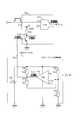
- the ignition device 7z is common in that it has an auxiliary power source 5z that inputs energy downstream of the primary coil 20 of the ignition coil 2 after the start of discharge.
- the engine water temperature TWE, the crank angle CA, the accelerator opening THL, and the engine speed detected by the operating condition detecting means SEN that detects the operating condition of the internal combustion engine 9 in the engine control apparatus 8z provided outside.
- the operating state information INF such as NE is acquired.
- the engine control unit (ECU) 8z transmits a discharge switch drive pulse PLS calculated in advance by map processing or the like in order to supply discharge energy according to the driving situation.
- the discharge driver 57z that drives the discharge switch 56 outputs a gate voltage Vg that turns on and off at a predetermined duty ratio according to the discharge switch drive pulse PLS, and controls the opening and closing of the discharge switch 56.
- the ignition device 7z according to the comparative example is different in that the discharge switch 56 is controlled to be opened and closed based on the discharge switch drive pulse PLS generated according to the operation state.
- Example 1 of the present invention the difference between the operation of the ignition device 7 shown as Example 1 of the present invention and the operation of the ignition device 7 z shown as Comparative Example 1 will be described.
- the specific voltage values and current values shown in each chart are merely examples, and can be changed as appropriate, and do not limit the present invention.
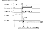
- the ignition switch 4 is turned on / off according to the ignition signal IGt transmitted from the ECU 8 in accordance with the ignition timing of the internal combustion engine 9.
- the closing of the ignition switch 4, as shown in the figure (k) when the primary current I 1 flowing in the primary coil 20 is interrupted, as shown in the figure (e), second ignition coil 2 A high secondary voltage V 2 is generated in the secondary coil 21 and applied to the spark plug 3.
- the insulation between the center electrode (not shown) and the ground electrode, which are exposed in the combustion chamber and face each other with a predetermined discharge gap therebetween, is broken, and discharge is started.
- the capacitor 54 provided as the discharge energy storage means in the auxiliary power source 5 needs to store sufficient energy before the discharge period signal IGw rises.
- the battery is charged to a high discharge voltage Vdc (for example, 100 V to several hundreds V).
- Vdc for example, 100 V to several hundreds V.
- the energy stored in the choke coil 50 is stored in the capacitor 54 by opening and closing the charge switch 51 in synchronization with the rising of the ignition signal IGt, as shown in FIG. While the ignition signal IGt is high (H), the battery is charged so as to have a high discharge voltage Vdc as shown in FIG. Note that charging of the capacitor 54 is not necessarily started in synchronization with the transmission of the ignition signal IGt, and may be performed at any time other than the time during which the discharge period signal IGw is transmitted.
- the figure (b), (c), the discharge period signal IGw is at high (H), and the feedback signal S FB is, when it comes to high (H), as shown in the figure (d)
- the FET drive signal PFB consisting of the logical product is turned ON, and the discharge from the auxiliary power source 5 is started.
- the voltage V 2 of the secondary coil 21 is also increased, the secondary current I 2 is increased, and the discharge is maintained.
- the output of the comparator 610 becomes high (H) as shown in FIG.
- the feedback signal S FB becomes low (L) as shown in FIG. 10C
- the FET drive signal P FB is turned off as shown in FIG. Stopped.
- the threshold changeover switch 621 is turned on, and the inverting input ( ⁇ ) has a control voltage + B as a resistance (R) in which a voltage dividing resistor 612 (R 12 ), a voltage dividing resistor 611 and a voltage dividing resistor 613 are connected in parallel. 11 // R 13 ), the lower limit voltage threshold V THF is input.
- the secondary current I 2 gradually decreases as shown in FIG. 9H, and the secondary current detection voltage V I2 becomes the lower limit as shown in FIG. Below the voltage threshold VTHF, the output VOUT of the comparator 610 becomes low (L) as shown in FIG.
- the feedback signal S FB becomes high (H)
- the FET drive signal P FB is turned on
- the discharge from the auxiliary power source 5 is started
- the secondary current I 2 is raised again.
- the secondary current I 2 is based on the upper limit voltage threshold V THR as a reference.
- the threshold is determined with reference to the lower limit voltage threshold VTHF , and the determination result is fed back to the opening / closing drive of the discharge switch 56.
- the secondary current I 2 can be maintained within a certain range without changing the polarity.
- the secondary current detection voltage V I2 is the upper limit voltage threshold value V THR , the lower limit voltage, as shown in FIG. even after exceeding the threshold V THF, some of overshoot OS can be seen.
- the threshold value since it is not necessary to input the threshold value from the outside, feedback control can be realized with high accuracy with a very simple configuration.
- the secondary voltage V 2 as a whole increases and gradually discharges while the secondary voltage V 2 repeatedly increases and decreases depending on the operating condition of the internal combustion engine 9.
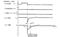
- Comparative Example 1 by the opening and closing of the ignition switch 4, after the higher secondary voltage V 2 is applied to the spark plug 8, that discharge is started from the auxiliary power supply 5z is the same as in Example 1. However, in Comparative Example 1, a map in which the duty ratio is set in advance is prepared in advance in anticipation of the increase in the secondary voltage V 2 z in the ECU 8z in accordance with the operation state of the internal combustion engine.
- the driving pulse PLS is transmitted, and the driving voltage Vg for opening and closing the discharge switch 56 is generated by the driving pulse PLS.
- the conditions prepared in advance in the map and the actual conditions do not always completely coincide with each other due to aging deterioration of each operation state detection means SEN, aging deterioration of the fuel injection valve, and the like. Absent.
- the map may be set so that the discharge energy supplied from the auxiliary power supply 5z is increased so that the secondary current I 2 z equal to or greater than the blow-off limit current Ith is always maintained. .
- the secondary current detection voltage V I2 is determined as a threshold value so that the secondary current I 2 is in a certain range regardless of the change of the secondary voltage V 2 , The result is fed back to supply and stop of discharge energy from the auxiliary power source 5.
- Comparative Example 1 to predict the increase in the secondary current I 2, to control supply and stop of the discharge energy from the auxiliary power 5z, according to a map prepared in advance, and controls the opening and closing of the discharge switch 56 ing.
- the secondary current I 2 is kept constant by feedback control. It is adjusted within the range.
- the secondary current I 2 z can be adjusted and stabilized in a certain range at medium speed.
- the input energy from the auxiliary power source 5z becomes excessive. There is a fear.
- the ECU 8z side performs map processing according to the driving information INF indicating the driving situation from the driving situation detection means SEN, and generates the driving pulse PLS for driving the discharge switch 56z. For this reason, the calculation load to ECU8z is large. In particular, at the time of ignition, since various calculations such as fuel injection control are performed simultaneously using the driving information INF transmitted from the driving condition detecting means SEN, it is desirable to reduce the calculation burden on the ECU as much as possible. .
- the ignition device 7b in the 2nd Embodiment of this invention is demonstrated.
- the configuration similar to that in the above embodiment is omitted, and only the configuration of the feedback control unit 6b and the drive driver 57b, which are characteristic of the present embodiment, is shown.
- the configuration is shown in which hysteresis is generated by driving the threshold value changeover switch 621 using the output V OUT of the comparator and changing the voltage input to the inverting input ( ⁇ ).
- the secondary current detection voltage V I2 is input to the inverting input ( ⁇ ), and the control voltage + B of the control power source 623 is divided by the voltage dividing resistors 611b and 612b to the non-inverting input (+). input.
- the present embodiment is different in that hysteresis is formed by feeding back the output Vout of the comparator 610 via the lower limit threshold voltage dividing resistor 613b. Further, in this modification, the output Vout pulled up to the control power source 623 via the pull-up resistor 614b is connected to the base (B) of the output inverting switch 622b built in the drive driver 57b, and the emitter ( E) is grounded.
- the collector (C) of the output inverting switch 622b is raised to the control voltage V + B via the pull-up resistor 620b, and the output is connected to the AND circuit 570b. Even in such a configuration, the same function as in the first embodiment can be exhibited.
- the secondary current feedback control means 6c includes a secondary current feedback control circuit 61c, a discharge blow-off detection means IG F U62, and a secondary current command value calculation means. 63 and the secondary current learning means 64 are different.
- Discharge blowout detection means IG F U62 detects the presence or absence of the occurrence of discharge blowout of the secondary current I 2 by the in-cylinder air flow through the combustion chamber, it transmits the discharge blowout signal IG F.
- the secondary current command value calculating means 63 calculates a target secondary current target value I 2 I according to the driving situation.
- the secondary current learning means 64 corrects the target secondary current target value I 2 I according to the presence or absence of discharge blow-off.
- the discharge blow-off detection means IG F U62, the secondary current command value calculation means 63, and the secondary current learning means 64 may be provided in the secondary current feedback control means 6, As shown in the figure, a part (secondary current command value calculation means 63, secondary current learning means 64) may be provided on the ECU 8c side.
- the threshold value of the current value is determined in the following embodiments, the detection current value and the current threshold value are appropriately converted into voltages, so that the handling becomes easy, and an analog circuit such as a comparator, or a digital A predetermined threshold value can be determined instantaneously by the analog hybrid circuit.
- the discharge blow-off detection means IG F U62 compares the secondary current I 2 detected by the secondary current detection means 60 with a predetermined blow-off detection current threshold value I LL, and when it falls below a predetermined value, the discharge blow-off occurs. it is determined that has occurred, and outputs the discharge blowout signal IG F.
- the secondary current conversion voltage V I2 obtained by converting the secondary current I 2 into a voltage and the blowout detection current threshold conversion voltage V LL obtained by converting the blowout detection current threshold I LL into threshold values are determined by a comparator or the like. .
- the secondary current command value calculation means 63 calculates a target value I 2 I of the target secondary current I 2 according to the operating state of the internal combustion engine. Specifically, the secondary current target value I 2 I corresponding to the operation state such as the engine speed NE, the coolant temperature TWE, and the accelerator opening is stored in advance as map data. The secondary current command value calculation means 63 selects an appropriate secondary current target value I 2 I from the map data based on the engine parameters input from the sensors SEN provided on the internal combustion engine 9 side to the ECU 8c, The secondary current feedback control circuit 61c outputs the secondary current switching signal IGA.
- the secondary current upper limit threshold I THR and the secondary current lower limit threshold I THF are set around the secondary current target value I 2 I, and the same feedback control as in the above embodiment is performed. The spark discharge by the secondary current of the same polarity is continued.
- Secondary current learning unit 64 blowout detection signal IG F, according the presence or absence of, performs increase or decrease of the secondary current correction learning value I 2 L for correcting the secondary current target value I 2 I.
- the secondary current learning unit 64 inputs the secondary current correction learned value I 2 L to the secondary current command value calculation unit 63.
- a new secondary current target value I 2 I + I 2 L obtained by correcting the secondary current target value I 2 I with the secondary current correction learning value I 2 L is input to the secondary current feedback control circuit 61c as new I 2 I. Then, control with a larger target of the secondary current I2 is performed.
- the secondary current command value calculation means 63 sets the secondary current basic command value I 2 I according to the driving situation, and the secondary current learning means 64 determines the secondary current correction learning.
- I 2 L 0 is set.
- step S110 it is determined whether or not learning is possible, that is, whether or not steady operation is being performed. Whether the operation is steady or not can be determined by engine parameters such as the engine speed NE obtained from various sensors SEN provided in the internal combustion engine 9. If the operation is in steady operation, the determination is Yes, and the process proceeds to step S120. If the timing is other than normal operation, the determination is No and the loop of step S110 is repeated.
- the secondary current monitor process step S120 monitoring is input to the secondary current feedback control circuit secondary current I 2.
- the process proceeds to the blowout occurrence determination process in step S130.
- the blowout occurrence determination process in step S130 determines the presence or absence of occurrence of blow out on whether or not the secondary current I 2 is reduced to near 0 mA. If blow-off is detected within a predetermined learning period (discharge period) in one combustion stroke, the determination is Yes, and the flow proceeds to step 150. If blow-off is not detected, determination No. Thus, the flow proceeds to step S140.
- blow-off detection current threshold I LL is set to a predetermined value (for example, 0 to 50 mA) that is equal to or less than the blow-out limit current Ith. Note that in the determination of the presence or absence of the blowout, may be determined that in E blowout in one detection, in order to prevent malfunction, the secondary current I 2 a plurality of times in a single determination period It may be determined that the blow-off has occurred when the blow-off detection current threshold value I LL falls below.
- step S140 determination is made based on whether or not blowout has occurred within the set period. If there is no blow-off within a predetermined period and the combustion state is stable, the determination is Yes and the flow proceeds to step S160. If blow-off is detected, the determination is No and the flow proceeds to step S170. .
- the amount of increase at one time is, for example, 10 mA to 50 mA and increases stepwise.
- step S160 to decrease the correction learning value I 2 L, the process proceeds to step S170. If the combustion is stable, by reducing the target value of the secondary current I 2, it is to suppress the waste of energy.
- the secondary current learning means 64 stores the sum of the basic command value I 2 I and the corrected learning value I 2 L as the secondary current command value I 2 I. Thereby, in the secondary current feedback control circuit 61c, feedback control is performed so that a predetermined current range is obtained with reference to the corrected secondary current command value I 2 I as the secondary current target value.
- step S180 the end of learning control is determined. If the learning control has not ended, the determination is no, the process returns to step S100, and the loop of steps S110 to S170 is repeated with the corrected secondary current threshold I 2 I as a reference.
- FIG. 1 shows the secondary current waveform when blow-off occurs due to a strong in-cylinder air current
- this figure (b) shows the secondary voltage waveform at that time
- this figure (c) The primary current waveform is shown.
- the secondary current I 2 is detected regardless of the change of the secondary voltage V 2 , and the two as the next current I 2 becomes constant in the range while maintaining the same polarity, by performing the secondary current feedback control for controlling the discharge from the auxiliary power supply 5, just enough, discharge energy from the auxiliary power supply 5 could be supplied.
- it occurs is stretching of the discharge arc by a very strong in-cylinder air flow, as shown in the figure (b), when the secondary voltage V 2 becomes very high, too late supply of discharge energy from the auxiliary power supply 5 As shown in the figure (a), it has been found that blowout may occur.
- amendment of the secondary current target value of the ignition device 7c in 3rd Embodiment is demonstrated.
- the necessity of correction is determined during the discharge period Tw according to the secondary current learning method described above.
- the corrected learning value I 2 L is increased, the target value is raised to the secondary current specified value I 2 I obtained by adding the corrected learning value I 2 L to the reference specified value I 2 I, and the corrected value Feedback control is performed around the secondary current specification value I 2 I. For this reason, even if the discharge is extended due to a strong in-cylinder airflow, the target value of the secondary current is high, so that a large amount of discharge energy is released from the auxiliary power source 5 and the discharge is not blown out. Can be maintained.
- the next discharge is performed with reference to the corrected target value I 2 I, and it is determined whether or not the blow-off has occurred within a predetermined determination period.
- the secondary current specified value is increased or decreased according to the correction flow described above.
- a reference designation value I 2 I is provided for the secondary current I 2 for each cylinder, and the result of the blow-off detection performed during each discharge period is shown. Accordingly, the corrected learning value I 2 L is increased or decreased.
- the secondary current learning means converts the correction learning value I 2 L of each cylinder into data corresponding to the correction amount, and transmits it as bit data arranged in the cylinder order from the ECU 8c to the secondary current feedback control circuit 6c. You can also
- the input energy after ignition is matched to the conventional cylinder with the poorest ignitability.
- the problem of supplying excess ignition energy to other cylinders can be solved, and the discharge energy can be managed more finely for each cylinder.
- the secondary current learning correction is not necessarily performed in each combustion stroke, and may be performed every certain update period.
- the secondary current target value I 2 I determination value I LL is set to a constant value in the entire range of the discharge period.
- the secondary current target value I 2 I, determination A bias may be provided so that the value I LL decreases with time.
- the secondary current target value I 2 I and the determination value I LL may be decreased stepwise. Also in this modification, the effect similar to the modification shown to FIG. 11A and FIG. 11B is exhibited.
- the secondary current feedback control means 6e includes a secondary current feedback control circuit 61e, a discharge blow-off detection means IG F U62e, and secondary current learning.
- the point provided with the means 64 is common to the ignition devices 7c and 7d in the third and fourth embodiments.
- Discharge blowout detection means IG F U62e detects the presence or absence of blowout of occurrence of the secondary current I 2 by the in-cylinder air flow through the combustion chamber, it transmits the discharge blowout signal IG F.
- the secondary current learning unit 64 includes a secondary current command value calculating unit 63 that calculates a target secondary current target value I 2 I according to the driving situation, and a target secondary according to the presence or absence of discharge blow-off. The current target value I 2 I is corrected.
- the discharge blow-off detection means IG F U62e detects not only the blow-off but also abnormalities of the ignition coil 2, the ignition switch 4, and the auxiliary power source 5 based on the secondary current I 2 to perform self-diagnosis.
- the difference is that it also serves as a self-diagnosis unit (DIU) 62e that transmits the signal DI to the ECU 8e.
- the self-diagnosis device 62e in the present embodiment receives the discharge period signal IGw, and at a predetermined discharge timing (a first abnormality determination delay time ⁇ 1 and a second abnormality determination delay time ⁇ 2 described later) during the discharge period.
- ignition is performed.
- a predetermined secondary current threshold a first delay time current threshold I D1 and a second delay time current threshold I D2 described later. Any abnormality can be identified by an abnormality determination method to be described later regarding abnormality of the coil 2, the ignition switch 4, and the auxiliary power source 5 (energy input unit).
- the detection result of the secondary current I2 is fed back to the open / close control of the discharge switch 56, and the secondary current I2 is kept in the same range with the same polarity, so It is possible to achieve both suppression and optimization of discharge energy. Also in this embodiment, modifications of the above embodiment can be adopted as appropriate.
- Self-diagnosis device 62e in the present embodiment that constitutes the abnormality determination means, at least, the secondary current I 2, at a first delay time current threshold I D1 or more and the second delay time current threshold I D2 or
- a normal determination step (S330) for determining that the ignition coil 2, the ignition switch 4, and the auxiliary power source 5 are normal is executed.
- the abnormality determining means determines that the auxiliary power source 5 has some abnormality when the secondary current I 2 is equal to or higher than the first delay time current threshold I D1 and lower than the second delay time current threshold I D2.
- An auxiliary power supply abnormality determination step (S340) for determination is executed.
- the abnormality determination means determines that there is an abnormality in either the ignition coil 2 or the ignition switch 4 when the secondary current I 2 is lower than the first delay time current threshold I D1.
- the determination process (S310) is executed.
- the ECU 8e determines whether or not the energization start of the ignition coil 2 is necessary. That is, when energization to the ignition coil 2 is started, the determination becomes Yes, and the process proceeds to step S210. If it is not time to start energization of the ignition coil 2, the determination of No is made and the loop of step S200 is repeated until the determination is Yes. Whether to start energizing the ignition coil 2 is determined based on the crank angle CA or the like input to the ECU 8e.
- the ECU 8e outputs the ignition signal IGt.
- the ignition switch 4 is turned on in response to the ignition signal IGt being turned on, energization from the battery 1 to the ignition coil 2 is started, The primary coil 20 is charged.
- the flow proceeds to the ignition timing determination process in step S220 while maintaining the state where the ignition signal IGt is activated.
- step S230 If the ignition timing corresponding to the operation status of the internal combustion engine has been reached, the determination becomes Yes, and the flow proceeds to step S230. If the ignition timing has not been reached, the determination is No, and the loop of step S220 is repeated until the determination timing is reached. In the ignition stroke in step S230, the ECU 8e stops the ignition signal IGt.
- the ECU 8e stores a map set in advance according to the operating state of the engine, and determines the necessity of auxiliary energy according to the map according to the engine parameter. If it is determined that discharging from the auxiliary power source 5 is necessary in the map area where energy input is required, the determination becomes Yes, and the flow proceeds to step S250. If it is determined that the discharge from the auxiliary power source 5 is unnecessary in the map area where energy input is not required, the determination is No and the flow proceeds to step S260.
- the discharge energy input period Tw, the first delay time current threshold I D1 , the second delay time current threshold I D2 , the first abnormality determination delay time ⁇ 1, the second An abnormality determination delay time ⁇ 2 is set.
- a third delay time current threshold I D3 and a third abnormality determination delay time ⁇ 3 are set.
- steps S250 and S260 a specific set value is selected from map data prepared in advance according to the driving situation.
- the discharge period signal IGw is output.
- the discharge switch 56 is driven to open and close, and input of discharge energy from the auxiliary power source 5 is started. Discharge from the auxiliary power supply 5, as the secondary current I 2 by the secondary current feedback control circuit 6e described above becomes a certain range, it is feedback controlled.
- the first delay time elapsed determination step in step S280 it is determined whether or not the first delay time ⁇ 1 has elapsed since the rising of the discharge period signal IGw.
- step S290 If the first delay time ⁇ 1 has elapsed from the rise of IGw, the determination becomes Yes, and the flow proceeds to step S290. If the first delay time ⁇ 1 has not elapsed, the determination is No, and the loop of step S280 is repeated until the delay time ⁇ 1 is reached.
- step S290 the threshold determination by comparing the first delay time ⁇ 1 which is detected by the secondary current detecting means 60 secondary current I 2 and the first delay time current threshold I D1 Done. Determination Yes and if the absolute value of the secondary current I 2 is the first delay time current threshold I D1 above, the flow proceeds to step S300.
- step S310 Determination No and if the absolute value of the secondary current I 2 is less than the first delay time current threshold I D1, the flow proceeds to step S310.
- the ignition coil and ignition switch abnormality determination process of step S310 the the absolute value of the secondary current I 2 is below the first delay time current threshold I D1, self-diagnosis device 62e is the ignition coil 2 or the ignition switch 4 It is determined that an abnormality has occurred in any of them, and a corresponding self-diagnosis signal D1 is transmitted to the ECU 8e. Thereafter, the flow proceeds to step S360.
- step S300 it is determined whether or not the second delay time ⁇ 2 has elapsed since the rising of the discharge period signal IGw. If the second delay time ⁇ 2 has elapsed from the rise of IGw, the determination becomes Yes, and the flow proceeds to step S320.
- step S320 the threshold determination by comparing the secondary current I 2 in the second delay time ⁇ 2 detected by the secondary current detector 60 and the second delay time current threshold I D2 Done.
- step S330 Determination Yes and if the absolute value of the secondary current I 2 is a second delay time current threshold I D1 above, the flow proceeds to step S330. Determination No and if the absolute value of the secondary current I 2 is less than the second delay time current threshold I D2, the flow proceeds to step S340.
- step S330 at predetermined timing, the secondary current I 2, at a first delay time current threshold I D1 or more and has a second delay time current threshold I D2 above, ignition It is determined that all of the coil 2, the ignition switch 4, and the auxiliary power source 5d are normal, and the flow proceeds to step S350.
- step S340 The auxiliary power source abnormality determination process of step S340, the secondary current I 2, at a first delay time current threshold I D1 above, and, since the second delay time below a current threshold I D2, the ignition coil 2 and an ignition switch 4 is not abnormal, and it is determined that there is some abnormality in the auxiliary power source 5d. For this reason, the self-diagnosis device 62e transmits the corresponding self-diagnosis signal D1 to the ECU 8e, and the flow proceeds to step S360.
- step 350 it is determined whether or not the discharge period Tw has elapsed. If the discharge period Tw has elapsed, the determination is yes, and the flow proceeds to step S360. The determination No is made until the discharge period Tw elapses, and the loop of step S350 is repeated until the discharge period Tw elapses.
- step S360 the discharge period stop process in step S360, the discharge period signal IGw is stopped, and the abnormality determination process in the case where the discharge of energy from the auxiliary power source 5d is required is completed.
- step S240 if it is determined in step S240 that it is not necessary to input energy from the auxiliary power source 5d, the process proceeds to step S260, and further proceeds to step S370.
- step S370 In the third delay time elapsed determination process of step 370, the third delay time ⁇ 3 is reached. It is determined whether or not elapses.
- step S290 If the third delay time ⁇ 3 has elapsed since the fall of IGt, the determination is yes, and the flow proceeds to step S290. If the third delay time ⁇ 3 has not elapsed, the determination is No, and the loop of step S280 is repeated until the delay time ⁇ 1 is reached.
- step S400 The absolute value of the secondary current I 2, when it is the third delay time current threshold I D3 above, the determination Yes, and the flow proceeds to step S400.
- the ignition coil and ignition switch normality determination process of step S400 the discharge current I 2 flowing when a high voltage is applied to the spark plug from the ignition coil 2 is above a predetermined current threshold, the ignition coil 2 and an ignition switch 4
- the self-diagnosis device 62e determines that it is normal. Thereafter, the abnormality determination flow ends.
- step S390 the secondary current I2 is not detected, since below a predetermined current threshold I D3, self-diagnosis device 62e, the ignition coil 2 or there is some abnormality in the ignition switch 4 And the corresponding self-diagnosis signal D1 is transmitted to the ECU 8e. Thereafter, the abnormality determination flow ends.
- the flow of the abnormality determination unit is executed in conjunction with the ECU 8e and the self-diagnosis device 62e (S280 to S350, S370 to S400).
- the ECU 8e realizes the function of the self-diagnosis device 62e. You may comprise.
- the effect of the abnormality determination means provided in the ignition device 7e of FIG. As shown in FIG. 16A, when all of the ignition coil 2, the ignition switch 4, and the auxiliary power source 5d are normal, the secondary current I 2 is set to predetermined threshold values I D1 and I D2 at predetermined abnormality determination timings ⁇ 1 and ⁇ 2. Based on this, it is judged normal.
- FIG. 16B shows a case where the discharge switch 56 is not activated due to overcurrent or the like.
- the discharge switch 56 operates after ignition, but the discharge switch 56 does not operate even if the drive signal VG56 is output from the discharge driver 57d for driving the discharge switch 56 thereafter.
- the second delay time .tau.2 since the discharge current flows only by spark discharge when the normal ignition coil 2 secondary voltage V 2 is applied, the secondary current I 2, the second delay Below the time current threshold ID2 . For this reason, it can be seen that the auxiliary power source 5 is not discharged, and an abnormality of the auxiliary power source 5 can be detected.
- the auxiliary power supply 5d is normal, if the abnormality in the ignition coil 2 or the ignition switch 4 is caused, because after opening of the ignition signal IGt, the secondary current I 2 does not flow, the first, second In both of the delay times ⁇ 1 and ⁇ 2, it is possible to detect that an abnormality has occurred in the ignition coil 2 or the ignition switch 4 below the predetermined threshold values I D1 and I D2 .
- the ignition coil 2 when an abnormality in any one of the ignition switch 4 occurs, the discharge current I 2 does not flow, the fall of the ignition signal IGt To the second delay current I 2 in the third delay time ⁇ 3 is equal to or less than a predetermined threshold ID 3 . Therefore, it can be detected that any abnormality has occurred in either the ignition coil 2 or the ignition switch 4.
- the second delay time current threshold I D2 in the second delay time ⁇ 2 is changed according to the difference in the secondary current target value I 2 I.
- the abnormality determination in response to any of the secondary current target value I 2 I.
- the abnormality determining means further detects the secondary voltage V 2 to 62e secondary voltage detecting means (66, 67) and an abnormality determination unit 62f including a secondary voltage determination unit 68.
- the secondary voltage V 2 becomes low, when the noise prevention resistor incorporated in the spark plug 3 resistance abnormality occurs, the secondary voltage V 2 Get higher.
- the measured secondary voltage V 2 and secondary current I 2 are determined to be abnormal under the operating conditions in which no strong in-cylinder airflow is generated in the combustion chamber when stopping or idling, and blowout does not occur reliably.
- the threshold value in the means 62f it is possible to detect an abnormality of the spark plug 3 such as a smoldering abnormality or a resistance value abnormality.
- the present embodiment comprises a secondary voltage detecting means for detecting the secondary voltage V 2 (66 and 67), the abnormality determining unit 62f is the secondary voltage V 2, the predetermined smoldering determination voltage threshold V 2 th1 Then, a comparison is made with a predetermined resistance abnormality determination voltage threshold V 2 th2. Determining time indicating the detected secondary voltage V 2 is smoldering determination voltage value lower than the threshold V 2 th1 is a smoldering occur when exceeding a predetermined time.
- the resistance abnormality determination voltage threshold V 2 th2 When the detected secondary voltage V 2 is higher than the resistance abnormality determination voltage threshold V 2 th2 for a predetermined time, it is determined that the resistance value is abnormal. Time indicating the detected secondary voltage V 2 is smoldering determination voltage value lower than the threshold V 2 th1 is within a predetermined time, and the time indicating the value higher than the resistance abnormality determination voltage threshold V 2 th2 is predetermined If it is within this time, it is determined as normal.
- predetermined voltage dividing resistors 66 and 67 are arranged as secondary voltage detecting means between the secondary coil 21 of the ignition coil 2 and the spark plug 8.
- the secondary voltage V 2 prorated by the voltage dividing resistors 66 and 67 is input to the secondary voltage determination means 68 provided in the feedback control means 6f in the present embodiment, and given predetermined threshold values V 2 th1 and V 2 th2 The threshold value is determined.
- the abnormality determination means 62f can detect occurrence of smolder abnormality and occurrence of resistance value abnormality.
- step S500 it is determined whether or not the discharge period signal IGw is on. If the discharge period signal IGw is in the discharge period, the determination is Yes, and the flow proceeds to step S510. If it is not within the discharge period, the determination is No, and the loop of step S510 is repeated until the discharge period is reached.
- Step S510 The smoldering determination step, the secondary voltage and the determination voltage threshold V 2 th1 smolder and detected secondary voltage V 2 by the detection means 66 and 67 are compared, smoldering discharge voltage V 2 reaches a predetermined determination voltage threshold V 2 It is determined whether or not smoldering occurs (plug resistance is low) depending on whether or not the period determined to be lower than th1 is continued for a predetermined time. Determining if the period of the discharge voltage V 2 is determined to be lower than the smoldering determination voltage threshold V 2 th1 continues more than a predetermined time is Yes, the flow proceeds to step S520.
- step S520 determines a discharge voltage V 2 is for less time than a predetermined threshold value is continued for a predetermined time or more, a smoldering occurs.
- step S510 the discharge voltage V 2 is increased within a certain time, when more than a predetermined smoldering determination voltage threshold V 2 th1, the determination becomes No, the flow proceeds to step S530.
- the discharge voltage V 2 is the time to be higher than the determination voltage threshold V 2 th2 predetermined resistance abnormality whether to continue more than a predetermined time is determined. If the period of the discharge voltage V 2 exceeds the resistance abnormality determination voltage threshold V 2 th2 is continued for a predetermined time or more, the determination Yes, and the flow proceeds to step S540.
- the resistor abnormality determination process of step S540 the discharge voltage is determined V 2 is the predetermined resistance abnormality determination voltage threshold V 2 th2 becomes higher time than is continued over a predetermined time period the order built abnormal resistance.
- step S510 the discharge voltage V 2 decreases within a predetermined time, if below a predetermined resistance abnormality determination voltage threshold V 2 th2, the determination becomes No, the flow proceeds to step S550.
- the normality determination process of step S550 the discharge voltage V 2 exceeds the predetermined smoldering determination voltage threshold V 2 th1 within a predetermined time period, and the discharge voltage V 2 is predetermined resistance abnormality determination voltage threshold V 2 th2 within a predetermined time period Therefore, it is determined to be normal. If any determination is made, the plug abnormality determination process is terminated.
- the plug abnormality determination (S500 to S550) is executed at a timing such as during stable running or idling.
Landscapes
- Engineering & Computer Science (AREA)
- Chemical & Material Sciences (AREA)
- Combustion & Propulsion (AREA)
- Mechanical Engineering (AREA)
- General Engineering & Computer Science (AREA)
- Signal Processing (AREA)
- Physics & Mathematics (AREA)
- Plasma & Fusion (AREA)
- Ignition Installations For Internal Combustion Engines (AREA)
Abstract
Description
特許文献1の点火装置では、点火コイルの二次側コイルを介して点火プラグに給電することで、放電開始後の放電継続時間を延ばし、安定した着火を図ろうとしている。
図1を参照して、本発明の第1の実施形態における点火装置7の概要について説明する。なお、本出願書類の説明において、正負の符号は電流の向きを示すものであるので、電流の大小は絶対値の大小を基準として表し、電流の増加若しくは上昇とは、電流の絶対値が大きくなる場合を意味し、電流の減少若しくは低下とは、絶対値が小さくなる場合を意味する。
点火装置7は、直流電源1と、点火コイル2と、点火プラグ3と、点火スイッチ4と、補助電源5と、本実施形態における要部である二次電流フィードバック制御手段6とによって構成されている。
点火装置7によれば、二次電流フィードバック制御手段6によって補助電源5からの放電エネルギの投入を内燃機関9の運転状況にかかわらず過不足なく制御して、常に安定した放電を維持し、燃焼室内に導入された混合気の着火を行うことができる。
本発明によれば、二次電流I2の極性が切り換わることなく一定の範囲に維持継続されることで、混合気へのエネルギ投入が連続的に行われるので、二次電流I2の0クロス付近への低下による吹き消えや、二次電流I2の極性の切り換えによる吹き消えの防止を図ることができるのである。
また、直流電源1として、バッテリ電圧をDC-DCコンバータ等によって昇圧したものを用いることもできる。
点火コイル2は、直流電源1からの通電の遮断によって一次側コイル20の電流を増減したときに二次側コイル21に高電圧を発生する。
一次側コイル20は、図略の中心コアの周囲を取り囲むように設けた一次側ボビンに、公知の絶縁被覆を施した一次巻線を所定の巻回数N1(自己インダクタンス:L1∝N1 2)だけ巻回して構成されている。
二次側コイル21は、一次側コイル20の外周を覆うように設けた図略の二次側ボビンに公知の絶縁被覆を施した二次巻線を所定の巻回数N2(自己インダクタンス:L2∝N2 2)だけ巻回して構成されている。
整流素子22は、ダイオードが用いられ、二次側コイル21に流れる電流の向きを整流する。
さらに、一次側コイル20の下流側には、補助電源5が接続されている。
二次側コイル21の一方の端には整流素子22が接続され、さらに、二次電流検出手段60として設けた電流検出抵抗(R0:例えば、10Ω程度)を介して接地されると共に、二次電流フィードバック制御回路61に接続されている。
本発明において、点火コイル2には、プラグホール内に収容可能な、いわゆるスティック型の点火コイルと、プラグホールの上部に固定されたハウジング内に収容可能な、いわゆるプラグトップ型の点火コイルとのいずれも採用可能である。
点火プラグ3は、点火コイル2から高い二次電圧V2の印加によって、燃焼室内に火花放電を発生する。
点火スイッチ4の上流側端子(コレクタ:C)は、点火コイル2の一次側コイル20の下流側に接続され、点火スイッチ4の下流側端子(エミッタ:E)は、接地される。点火スイッチ4の駆動端子(ゲート:G)には、内燃機関9の運転状況に応じて、エンジン制御装置(ECU)8から発信された点火信号IGtが入力され、点火信号IGtの立ち上がりに同期してONとなり、点火信号IGtの立ち下がりに同期してOFFとなる。なお、ECU8は、各種センサ等を有する運転状況検出手段SENによって検出された、エンジン水温TWE、クランク角CA、アクセル開度THL、エンジン回転数NE等の内燃機関9の運転情報に基づいて運転状況を検出し、点火信号IGtや後述の放電期間信号IGwを出力する。
還流ダイオード401は、点火スイッチ4のコレクタCとエミッタEとの間に、エミッタ側(接地側)からコレクタ側(電源側)に向かう電流を許容し、逆向きの電流は阻止する整流素子である。
点火スイッチ4がOFFとなっている間でも、還流ダイオード401によって、バイパス経路が形成され、エミッタ側からコレクタ側に向かう電流を流すことができる。
これにより、点火スイッチ4の開閉により放電が開始された後に、後述する補助電源5から放電エネルギを点火コイル2の一次側コイル20の下流側に導入後、続いて、放電スイッチ56が遮断された場合に、点火コイル2→バッテリ1→GND→還流ダイオード401→点火コイル2という経路で点火コイル2の還流電流を流すことにより点火コイル2に流れる電流の連続性を維持できるようになる。
これによって、二次電流I2の極性が入れ換わることなく放電エネルギを導入し続けることができる。
また、補助電源5からのエネルギ投入期間は任意に設定することが可能である。
チョークコイル50には、所定の自己インダクタンス(L0:例えば、5~50μH)を有するコア付きコイルが用いられている。
チョークコイル50の上流側は、直流電源1に接続され、下流側は、充電スイッチ51を介して接地されている。
充電スイッチ51は、充電ドライバ52によって開閉制御される。
コンデンサ54には、整流素子55を介して放電スイッチ56が接続され、さらに、点火コイル2の一次側コイル20の下流側に接続されている。
整流素子53、55にはダイオードが用いられている。
整流素子53は、コンデンサ54からチョークコイル50、及び、充電スイッチ51側への電流の逆流を阻止している。
整流素子55は、点火コイル2からコンデンサ54への電流の逆流を阻止している。
チョークコイル50、充電スイッチ51、充電ドライバ52、整流素子53、放電エネルギ蓄積手段54によっていわゆるチョッパ型の昇圧DC-DCコンバータを構成している。
また、充電ドライバ52には、一般的に半導体素子の駆動に用いられている公知の駆動ドライバを適宜採用し得る。
放電スイッチ56を開閉駆動する放電ドライバ57は、ECU8から発信された放電期間信号IGwと後述するフィードバック制御手段6から発信されたフィードバック信号SFBとの論理積を求めるAND回路570を備える。また、放電ドライバ57は、AND回路570によって得られた論理積からなるフィードバック駆動信号PFBを、所定のゲート電圧Vgに増幅するゲート電圧増幅回路571を備える。
なお、本実施形態においては、二次電流I2は、二次電流検出抵抗60によって電圧換算された二次電流検出電圧VI2を閾値判定することになる。
また、本実施形態における二次電流フィードバック制御回路61は、一例として示すものであり、検出した二次電流I2を上下限設定した二つの閾値(VTHR/VTHF)で判定し、放電スイッチ56を開閉駆動することができれば、具体的な回路は適宜変更可能である。
二次電流フィードバック制御回路61は、コンパレータ610と、上限閾値分圧抵抗611、612と、下限閾値分圧抵抗613と、閾値切換スイッチ駆動電圧分圧抵抗615、616、と、プルアップ抵抗614、619と、出力反転用スイッチ駆動電圧分圧抵抗617、618と、プルダウン抵抗620と、閾値切換スイッチ621と、出力反転スイッチ622と、制御電源623とによって構成されている。
コンパレータ610の反転入力(-)には、上限電圧閾値VTHRと下限電圧閾値VTHFとが適宜切り換えられて入力される。
閾値切換スイッチ621には、MOSFET等の半導体開閉素子が用いられている。
閾値切換スイッチ621のソース(S)は、接地されている。
閾値切換スイッチ621のゲート(G)には、プルアップ抵抗614(R4)を介して制御電源623の制御電圧(V+B)につり上げられたコンパレータ610の出力を、閾値切換スイッチ駆動電圧分圧抵抗615(R5)、616(R6)によって分圧した電圧が入力されている。
コンパレータ610の出力にしたがって、閾値切換スイッチ621がオンオフされ、コンパレータ610の反転入力(-)に、二次電流検出電圧VI2が上昇しているときには、上限電圧閾値VTHRが入力される。また、二次電流検出電圧VI2が下降しているときには、下限電圧閾値VTHFがコンパレータ610の反転入力(-)に入力される。
例えば、制御電圧V+Bを5V、分圧抵抗R1、R2、R3をそれぞれ、1.6kΩ、2kΩ、2kΩとすると、
上限電圧閾値VTHR=1.6×5/(2+1.6)≒2.2V、
下限電圧閾値VTHF=(1.6//2)×5/(2+1.6//2)≒1.5V
となる。
二次電流検出電圧VI2を、例えば、1.5Vから2.2Vの範囲で閾値判定し、補助電源5からの放電と停止を制御することで、二次電流I2を、-150mAから-220mAの範囲で、極性を切り換えることなく維持することができる。
出力反転スイッチ622のドレイン(D)は、プルアップ抵抗619を介して、制御電源623に接続され、プルダウン抵抗620を介して放電ドライバ57に接続されている。
出力反転スイッチ622のゲート(G)には、プルアップ抵抗619を介して制御電源623の制御電圧V+Bにつり上げられたコンパレータ610の出力を、分圧抵抗617(R7)、618(R8)で分圧した電圧が入力されている。
このため、コンパレータ610の出力の変化にしたがって、出力反転スイッチ622がオンオフする。
コンパレータ610の出力がローのとき、即ち、二次電流I2(二次電流検出電圧VI2)が所定の下限電流閾値ITHF(下限電圧閾値VTHF)を下回ったときには、出力反転スイッチ622がオフとなり、フィードバック信号SFBは、プルアップ抵抗619及びプルダウン抵抗620、を介して制御電源623に接続されるので、1(ハイ)となる。
このため、放電期間信号IGwが1(ハイ)で、かつ、フィードバック信号SFBが1(ハイ)のとき、AND回路570の出力が、1(ハイ)となり、それ以外は、0(ロー)となる。AND回路570の出力は、ゲート電圧増幅回路571にフィードバックパルスPFBとして出力される。
ゲート電圧増幅回路571で増幅されたゲート電圧Vgが放電スイッチ56のゲート(G)に入力され、フィードバックパルスPFBのオンオフにしたがって、放電スイッチ56が開閉駆動される。
さらに、二次電流I2が、所定の下限電流閾値ITHFを下回った場合には、コンパレータ610の出力がローとなり、フィードバック信号SFBは、ハイとなる。これにしたがって、放電スイッチ56がオンとなり、補助電源5から放電エネルギの供給が開始される。下限電流閾値ITHFは放電エネルギ供給のオン閾値として機能する。
コンデンサ54から放電電圧Vdcで一次側コイル20の下流側に放電エネルギが重畳的に供給されると、電磁誘導によって、一次電圧V1の変化に対して、一次電圧V1の巻回比(N=N2/N1)に比例して二次側コイル21の二次電圧V2が変化し、二次電流I2が極性を切り換えることなく重畳的に流れ、放電の維持が図られる。
E1(t)=∫V1I1dt=εE2(t)=ε∫V2I2dtの関係が成り立つ。
内燃機関9の運転状況によって、二次電圧V2は刻々と変化し、特に、燃焼室内に強い筒内気流が発生している場合には、アーク放電の引き伸ばしによって、二次電圧V2の上昇が起こる。
しかし、本発明を用いれば、二次電圧V2が如何なる値であっても、二次電流I2をモニタし、二次電流I2が一定の範囲に収まるよう、上下限を設けて閾値判定し、その結果を放電スイッチ56の開閉制御にフィードバックする。これにより、補助電源5から点火コイル2に過不足なく放電エネルギE1(t)を投入することができる。
また、このとき、二次電流検出電圧VI2の上下限を示す閾値(VTHR/VTHF)は、二次電流フィードバック制御回路61内で自己完結的に生成することができるので、ECU8への演算負荷を少なくすることができる。
なお、本発明の点火装置と同一の部分には、同じ符号を付し、似て非なる部分には、アルファベットのzの符号を枝番として付したので、相違する部分を中心に説明し、同一の構成については説明を省略する。
なお、各チャートに示す具体的な電圧値、電流値は一例に過ぎず、適宜変更可能なものであり、本発明を限定するものではない。
点火スイッチ4の開閉により、本図(k)に示すように、一次側コイル20に流れていた一次電流I1が遮断されると、本図(e)に示すように、点火コイル2の二次側コイル21に高い二次電圧V2が発生し、点火プラグ3に印加される。これにより、燃焼室内に露出し、所定の放電ギャップを隔てて対向する図略の中心電極と接地電極との間の絶縁が破壊され、放電が開始される。
本実施形態においては、点火信号IGtの立ち上がりに同期して、本図(f)に示すように、充電スイッチ51を開閉することで、チョークコイル50に蓄えられていたエネルギをコンデンサ54に蓄積し、点火信号IGtがハイ(H)となっている間に、本図(g)に示すように、高い放電電圧Vdcとなるように充電されている。
なお、コンデンサ54の充電は、必ずしも、点火信号IGtの発信に同期して開始させる必要はなく、放電期間信号IGwが発信されている時間以外であれば、いつ行っても良い。
このため、コンパレータ610の反転入力(-)には、制御電源623の電圧+Bを分圧抵抗611、612で分圧した上限電圧閾値VTHRが入力されている。
本図(h)に示すように、二次電流I2が低下すると、これに伴い、本図(i)に示すように、二次電流検出電圧VI2が、下限電圧閾値VTHFを下回ることになる。すると、補助電源5からの放電を開始すべく、本図(c)に示すように、フィードバック信号SFBがハイ(H)となる。
本図(g)、(h)に示すように、補助電源5に設けたコンデンサ54からの放電が開始され、一次側コイル20の一次電圧V1が上昇し、巻回比Nに比例して、二次側コイル21の電圧V2も高くなり、二次電流I2が上昇し、放電の維持が図られる。
同時に、閾値切換スイッチ621がオンされ、反転入力(-)には、制御電圧+Bを分圧抵抗612(R12)と、分圧抵抗611と分圧抵抗613とを並列に接続した抵抗(R11//R13)とによって分圧された、下限電圧閾値VTHFが入力される。
これを繰り返すことで、二次電流検出抵抗60で検出した二次電流I2の変化にしたがって、二次電流I2が上昇しているときには、上限電圧閾値VTHRを基準とし、二次電流I2が下降しているときには、下限電圧閾値VTHFを基準として、閾値判定し、その判定結果を放電スイッチ56の開閉駆動にフィードバックする。これにより、本図(g)に示すように、二次電流I2の極性を変えることなく、一定の範囲に維持することができる。
このとき、本図(e)に示すように、内燃機関9の運転状況により、二次電圧V2が上昇と低下を繰り返しながら、全体として、二次電圧V2が上昇し、徐々に放電維持が困難となる傾向にある場合でも、検出した二次電流I2の変化によって、補助電源5からの放電と停止とを制御しているので、長期に亘って一定の範囲内に維持することが可能となり、安定した着火を実現できる。
本図(b)に示すように、放電期間信号IGwがローとなると、本図(d)に示すように、FET駆動信号PFBは強制的にオフとなり、補助電源5からの放電を終了する。
比較例1では、点火スイッチ4の開閉により、高い二次電圧V2が点火プラグ8に印加された後、補助電源5zからの放電が開始される点は、実施例1と同様である。
しかし、比較例1では、ECU8z内において、内燃機関の運転状況に応じて、二次電圧V2zの上昇を見越して、デューティ比を設定したマップを予め用意しておき、そのマップにしたがって、駆動パルスPLSを送信し、その駆動パルスPLSによって放電スイッチ56を開閉駆動する駆動電圧Vgを生成している点が相違する。
また、安全率を考慮して、必ず吹消限界電流Ith以上の二次電流I2zが維持されるように、補助電源5zから供給する放電エネルギが多くなるようにマップが設定されることもある。
その結果、本図(g)に示すように、吹消限界電流Ithを大きく上回る二次電流I2zが流れ、交叉斜線で覆った部分は、補助電源からの投入エネルギが過剰であったことがわかる。
実施例1においては、高速運転状況において、二次電圧V2の変化にかかわらず、二次電流I2が一定の範囲となるように、二次電流検出電圧VI2を閾値判定して、その結果を、補助電源5からの放電エネルギの供給と停止にフィードバックさせている。一方で、比較例1では、二次電流I2の増加を予測し、補助電源5zから放電エネルギの供給と停止を制御すべく、予め用意したマップにしたがって、放電スイッチ56の開閉駆動を制御している。
一方、比較例1においては、中速時には、一定の範囲に二次電流I2zを調整し、安定化することができる。しかし、内燃機関の高速時には、放電エネルギの供給が不足し、吹き消え限界電流Ith以下に二次電流I2zが低下するおそれがあり、低速時には、補助電源5zからの投入エネルギが過剰となるおそれがある。
しかも、比較例1では、ECU8z側で運転状況検出手段SENからの運転状況を示す運転情報INFにしたがってマップ処理を行って、放電スイッチ56zを駆動する駆動パルスPLSを生成している。このため、ECU8zへの演算負荷が大きい。特に点火時においては、運転状況検出手段SENから送信される運転情報INFを用いて、燃料の噴射制御等の様々な演算を同時進行で行うため、できるだけECUへの演算負担を軽減するのが望ましい。
図6を参照して、本発明の第2の実施形態における点火装置7bについて説明する。
なお、前記実施形態と同様の構成は省略し、本実施形態に特徴的な、フィードバック制御手段6b及び駆動ドライバ57bの構成についてのみを示す。
実施例1では、コンパレータの出力VOUTを利用して、閾値切換スイッチ621を駆動して、反転入力(-)に入力する電圧を変化させてヒステリシスを生成した構成を示した。一方、本実施形態では、反転入力(-)に二次電流検出電圧VI2を入力し、制御電源623の制御電圧+Bを分圧抵抗611b、612bで案分して非反転入力(+)に入力する。さらに、本実施形態では、下限閾値分圧抵抗613bを介して、コンパレータ610の出力Voutを、帰還させることで、ヒステリシスを形成するようにした点が相違する。
さらに、本変形例では、プルアップ抵抗614bを介して制御電源623にプルアップした出力Voutを駆動ドライバ57bに内蔵した出力反転スイッチ622bのベース(B)に接続し、出力反転スイッチ622bのエミッタ(E)を接地している。出力反転スイッチ622bのコレクタ(C)をプルアップ抵抗620bを介して制御電圧V+Bにつり上げて、その出力をAND回路570bに接続してある。
このような構成においても、実施例1と同様の機能を発揮できる。
図7を参照して本発明の第3の実施形態における点火装置7cについて説明する。
本実施形態においては、前記実施形態の構成に加えて、二次電流フィードバック制御手段6cが、二次電流フィードバック制御回路61cと、放電吹消え検出手段IGFU62と、二次電流指令値算出手段63と、二次電流学習手段64とを具備する点が相違する。放電吹消え検出手段IGFU62は、燃焼室内を流れる筒内気流による二次電流I2の放電吹消えの発生の有無を検出し、放電吹消え信号IGFを発信する。二次電流指令値算出手段63は、運転状況に応じて目標とする二次電流狙い値I2Iを算出する。二次電流学習手段64は、放電吹消えの有無に応じて目標とする二次電流狙い値I2Iを補正する。
実際の回路では、二次電流I2を電圧換算した二次電流換算電圧VI2と吹消え検出電流閾値ILLを電圧換算した吹消え検出電流閾値換算電圧VLLとをコンパレータ等で閾値判定する。
具体的には、エンジン回転数NE、冷却水温度TWE、アクセル開度等の運転状況に応じた二次電流狙い値I2Iを予めマップデータとして記憶する。二次電流指令値算出手段63は、ECU8cに内燃機関9側に設けたセンサ類SENから入力されたエンジンパラメータに基づいて、マップデータから適切な二次電流狙い値I2Iを選択し、二次電流切換信号IGAとして二次電流フィードバック制御回路61cに出力する。
二次電流フィードバック制御回路61cでは、二次電流狙い値I2Iを中心に二次電流上限閾値ITHR、二次電流下限閾値ITHFが設定され、前記実施形態と同様のフィードバック制御が行われ、同一極性の二次電流による火花放電が継続される。
二次電流狙い値I2Iの補正が必要と判断された場合には、二次電流学習手段64は二次電流補正学習値I2Lを二次電流指令値算出手段63に入力する。
二次電流狙い値I2Iを二次電流補正学習値I2Lによって補正した新たな二次電流狙い値I2I+I2Lが新たなI2Iとして二次電流フィードバック制御回路61cに入力され、二次電流I2の目標を大きくした制御が行われる。
ステップS100の初期値設定行程では、二次電流指令値算出手段63によって、運転状況に応じて二次電流基本指令値I2Iが設定され、二次電流学習手段64において、二次電流補正学習値の初期値として、I2L=0に設定される。
定常運転かどうかは、内燃機関9に設けられた各種センサSENから得られたエンジン回転数NE等のエンジンパラメータによって判断することができる。
定常運転中であれば、判定Yesとなり、ステップS120に進み、定常運転以外のタイミングであれば、判定Noとなり、ステップS110のループを繰り返す。
次いでステップS130の吹消え発生判定行程に進む。
ステップS130の吹消発生判定行程では、二次電流I2が0mA近くまで低下したか否かで吹消えの発生の有無を判定する。
一回の燃焼行程において所定の学習期間(放電期間)内に吹消えが検出された場合には、判定Yesとなり、フローはステップ150に進み、吹消えが検出されなかった場合には、判定Noとなり、フローはステップS140に進む。
吹消え検出電流閾値ILLは、吹き消え限界電流Ith以下の所定値(例えば、0~50mA)に設定される。
なお、吹消えの有無の判定において、一回の検出で吹消えありと判定しても良いし、誤作動を防ぐために、一回の判定期間内に複数回に亘って二次電流I2が吹消え検出電流閾値ILLを下回った時に吹き消えありと判定しても良い。
所定の期間内に吹消えがなく、安定した燃焼状態である場合には判定Yesとなり、フローはステップS160に進み、吹き消えが検出された場合には、判定Noとなり、フローはステップS170に進む。
一回の増加量は、例えば、10mA~50mAとし、段階的に増加する。
燃焼が安定している場合には、二次電流I2の狙い値を下げることで、エネルギの無駄を抑制するためである。
これによって、二次電流フィードバック制御回路61cにおいては、二次電流狙い値としての補正後の二次電流指令値I2Iを基準として所定の電流範囲となるようにフィードバック制御が実施される。
学習制御が終了していない場合には、判定Noとなり、ステップS100に戻り、補正後の二次電流閾値I2Iを基準として、ステップS110~S170のループが繰り返される。
なお、二次電流指令値I2Iの補正実施後は、規定の回数だけ補正後の制御値で作動させた後、
基準二次電流指令値に戻すようにしても良い。
本図(a)は、強い筒内気流によって、吹消えが発生したときの二次電流波形を示し、本図(b)は、そのときの二次電圧波形を示し、本図(c)は、一次電流波形を示す。
本発明の点火装置7cでは、放電期間Tw中に上述の二次電流学習方法に従って、補正の要否を判定する。
図10A中(b)に示すように、吹消えが検出された場合、吹消え検出信号IGFが立ち上がる。
このため、強い筒内気流によって、放電が引き延ばされても、二次電流の狙い値が高くなっているので、補助電源5から放電エネルギが多く放出され、吹き消えを生じることなく放電を維持できる。
その結果、二次電流学習手段の学習効果を反映するため図10Bに示すように、各気筒に応じた補正学習値を設定することもできる。具体的には、二次電流学習手段が各気筒の補正学習値I2Lを補正量に応じたデータに変換し、気筒順に並べたビットデータとしてECU8cから二次電流フィードバック制御回路6cに送信することもできる。
また、必ずしも、二次電流学習補正は、毎燃焼行程で行う必要はなく、一定の更新期間毎に行っても良い。
前記実施形態においては、二次電流狙い値I2I判定値ILLを放電期間の全範囲において一定の値に設定したが、本変形例のように、二次電流狙い値I2I、判定値ILLが時間の経過と共に減少するよう、バイアスを設けても良い。
これとは逆に、放電の後半は吹消え判定されてもすでに投入されている放電エネルギによって着火する可能性が比較的高いため、判定値ILLは低めに設定する。
本変形例においても、図11A、図11Bに示すように前記実施形態と同様の効果を発揮するのに加え、着火性に影響の少ない放電後半のエネルギ消費を抑制することができる。
本図に示すように、二次電流狙い値I2I、判定値ILLを段階的に減らすようにしても良い。
本変形例においても、図11A、図11Bに示した変形例と同様の効果を発揮する。
図13を参照して本発明の第4の実施形態における点火装置7dについて説明する。
本実施形態においても、前記実施と同様に二次電流フィードバック制御回路6dに入力された二次電流I2の閾値判定によって、放電スイッチ56が開閉されて一定の範囲となるようにフィードバック制御される。しかし、前記実施形態においては、ECU8cからフィードバック制御回路6cへ、一つの電流指定値I2Iが発信される構成を示したが、本実施形態の点火装置7dでは、電流切換信号IGAを、複数の電流切換信号IGA1、IGA2、・・・、IGAnとして構成して、二次電流フィードバック制御回路6dに送信するようにした点が相違する。
これによって、二次電流I2の狙い値を簡単に切換ることが可能となる。
図14を参照して本発明の第5の実施形態における点火装置7eの概要について説明する。
本実施形態においては、前記第1の実施形態の構成に加えて、二次電流フィードバック制御手段6eが、二次電流フィードバック制御回路61eと、放電吹消え検出手段IGFU62eと、二次電流学習手段64とを具備する点は、第3、第4の実施形態における点火装置7c、7dと共通する。放電吹消え検出手段IGFU62eは、燃焼室内を流れる筒内気流による二次電流I2の吹消えの発生の有無を検出し、放電吹消え信号IGFを発信する。二次電流学習手段64は、運転状況に応じて目標とする二次電流狙い値I2Iを算出する二次電流指令値算出手段63と、放電吹消えの有無に応じて目標とする二次電流狙い値I2Iを補正する。
本実施形態における自己診断装置62eは、放電期間信号IGwが入力され、放電期間中の所定の放電時期(後述する第1の異常判定遅延時間τ1、第2の異常判定遅延時間τ2)において、二次電流検出手段60によって検出された二次電流I2と所定の二次電流閾値(後述する第1の遅延時間電流閾値ID1、第2の遅延時間電流閾値ID2)との比較により、点火コイル2、点火スイッチ4、補助電源5(エネルギ投入部)の異常について後述する異常判定方法によって、いずれの異常かを特定することができる。
また、本実施形態においても、前記実施形態の変形例を適宜採用することもできる。
本実施形態においては異常判定手段を構成する自己診断装置62eが、少なくとも、二次電流I2が、第1の遅延時間電流閾値ID1以上で、かつ、第2の遅延時間電流閾値ID2以上のときには、点火コイル2、点火スイッチ4、及び、補助電源5が正常と判定する正常判定行程(S330)を実行する。さらに、異常判定手段は、二次電流I2が、第1の遅延時間電流閾値ID1以上で、かつ、第2の遅延時間電流閾値ID2を下回るときには、補助電源5に何らかの異常があると判定する補助電源異常判定行程(S340)を実行する。さらに、異常判定手段は、二次電流I2が、第1の遅延時間電流閾値ID1を下回るときには、点火コイル2又は点火スイッチ4のいずれかに異常があると判定する点火コイル・点火スイッチ異常判定行程(S310)を実行する。
ステップS200のコイル通電開始判定行程では、ECU8eは点火コイル2への通電開始の要否を判定する。
即ち、点火コイル2への通電を開始する場合には判定Yesとなり、ステップS210に進む。点火コイル2への通電を開始する時期でない場合には、判定Noとなり、判定Yesとなるまで、ステップS200のループを繰り返す。
点火コイル2への通電を開始するか否かは、ECU8eに入力されたクランク角CA等に基づいて判断される。
本図に示した異常判定フローとは別に、前述の通常の制御フローに従って、点火信号IGtのオンを受けて、点火スイッチ4がオン駆動され、バッテリ1から点火コイル2への通電が開始され、一次側コイル20が充電される。
次いで、点火信号IGtが作動した状態を維持したまま、フローはステップS220の点火時期判定行程に進む。
点火時期に達していない場合には、判定Noとなり、判定時期に到達するまで、ステップS220のループを繰り返す。
ステップS230の点火行程では、ECU8eは点火信号IGtを停止する。
二次電圧V2が、点火プラグ3の先端に設けた中心電極と接地電極との間の放電空間の絶縁耐圧を超えると電極間に火花放電が発生する。
一方、ステップS240の補助エネルギ要否判定行程では、補助電源5からの放電の要否が判定される。
エネルギ投入が必要と設定されたマップ領域においては補助電源5からの放電が必要と判断されると、判定Yesとなり、フローはステップS250に進む。エネルギ投入が不要と設定されたマップ領域においては補助電源5からの放電が不要と判断されると、判定Noとなり、フローはステップS260に進む。
ステップS260の主放電期間条件設定行程では、第3の遅延時間電流閾値ID3、第3の異常判定遅延時間τ3を設定する。
なお、ステップS250、S260において、具体的な設定値は、運転状況に応じて予め用意したマップデータから選択する。
IGwの出力を受けて、放電スイッチ56が開閉駆動され、補助電源5から放電エネルギの投入が開始される。
補助電源5からの放電は、前述の二次電流フィードバック制御回路6eによって二次電流I2が一定の範囲となるように、フィードバック制御される。
ステップS280の第1の遅延時間経過判定行程では、放電期間信号IGwの立ち上がりから第1の遅延時間τ1が経過したか否かが判定される。
第1の遅延時間τ1が経過していない場合には、判定Noとなり、遅延時間τ1に至るまでステップS280のループを繰り返す。
二次電流I2の絶対値が第1の遅延時間電流閾値ID1以上である場合には判定Yesとなり、フローはステップS300に進む。
ステップS310の点火コイル・点火スイッチ異常判定行程では、二次電流I2の絶対値が第1の遅延時間電流閾値ID1を下回っているので、自己診断装置62eは点火コイル2又は点火スイッチ4のいずれかに異常が発生していると判定し、対応する自己診断信号D1をECU8eに送信する。その後、フローはステップS360に進む。
IGwの立ち上がりから第2の遅延時間τ2が経過した場合には、判定Yesとなり、フローはステップS320に進む。
ステップS320の第2の異常判定行程では、二次電流検出手段60によって検出された第2の遅延時間τ2における二次電流I2と第2の遅延時間電流閾値ID2との比較による閾値判定が行われる。
二次電流I2の絶対値が第2の遅延時間電流閾値ID2を下回る場合には判定Noとなり、フローはステップS340に進む。
放電期間Twが経過した場合には、判定Yesとなり、フローはステップS360に進む。
放電期間Twが経過するまでは判定Noとなり、放電期間Twが経過するまでステップS350のループを繰り返す。
一方、ステップS240で補助電源5dからのエネルギ投入が不要と判断されステップS260に進み、さらに、ステップS370に進んだ場合、ステップ370の第3の遅延時間経過判定行程では、第3の遅延時間τ3が経過したか否かが判定される。
第3の遅延時間τ3経過していない場合には、判定Noとなり、遅延時間τ1に至るまでステップS280のループを繰り返す。
ステップS380の第3の遅延時間異常判定行程では、第3の遅延時間τ3における二次電流I2の絶対値と、第3の遅延時間電流閾値ID3との比較による閾値判定が行われる。
ステップS400の点火コイル・点火スイッチ正常判定行程では、点火コイル2から点火プラグに高電圧が印加されたときに流れる放電電流I2が一定の電流閾値を超えており、点火コイル2及び点火スイッチ4の異常はなく、自己診断装置62eは正常と判定する。その後、異常判定フローは終了する。
ステップS390の点火コイル・スイッチ異常判定行程では、二次電流I2が検出されず、所定の電流閾値ID3を下回るため、自己診断装置62eは、点火コイル2又は、点火スイッチ4に何らかの異常があると判定し、対応する自己診断信号D1をECU8eに送信する。その後、異常判定フローは終了する。
なお、本実施形態では、ECU8eと自己診断装置62e(S280からS350、S370からS400)の連動により上記異常判定手段のフローを実行しているが、ECU8eが自己診断装置62eの機能を実現するように構成してもよい。
図16Aに示すように、点火コイル2、点火スイッチ4、補助電源5dのいずれも正常な場合、所定の異常判定時期τ1、τ2において、二次電流I2が所定の閾値ID1、ID2に基づいて正常判定される。
図16Dに示すように、補助電源5を使用しない条件で、点火コイル2、点火スイッチ4のいずれもが正常な場合には、点火信号IGtの立ち下がりから第3の遅延時間τ3における二次電流I2が所定の閾値ID3以上であるため、正常であることが検出できる。
次に、図18A、図18B、図18Cを参照して、本発明の第6の実施形態における点火装置7fする。本実施形態の点火装置7fは、前記実施形態と同様の二次電流フィードバック制御手段(6~6e)を具備しつつ、異常判定手段62eにさらに二次電圧V2を検出する二次電圧検出手段(66、67)及び二次電圧判定手段68を加えた異常判定手段62fを備える。
図18Aに示すように、くすぶりを発生する場合には、二次電圧V2が低くなり、点火プラグ3に内蔵した雑音防止抵抗に抵抗値異常が発生した場合には、二次電圧V2が高くなる。
そこで、停止時やアイドリング時などの燃焼室内に強い筒内気流が発生しておらず、確実に吹消えを生じない運転条件において、測定した二次電圧V2及び二次電流I2を異常判定手段62fにおいて閾値判定することで、くすぶり異常や抵抗値異常等の点火プラグ3の異常を検出することが可能となる。
検出された二次電圧V2がくすぶり判定電圧閾値V2th1よりも低い値を示す時間が所定の時間を超える場合にはくすぶり発生と判定する。
検出された二次電圧V2がくすぶり判定電圧閾値V2th1よりも低い値を示す時間が所定の時間以内であり、かつ、抵抗異常判定電圧閾値V2th2よりも高い値を示す時間が所定の時間以内である場合には正常と判定する。
分圧抵抗66、67で案分された二次電圧V2は、本実施形態におけるフィードバック制御手段6fに設けた二次電圧判定手段68に入力され、所定の閾値V2th1、V2th2との閾値判定が行われる。
異常判定手段62fでは、くすぶり異常発生の検出と抵抗値異常発生の検出を行うことができる。
ステップS500の放電機関判定行程では、放電期間信号IGwがオンか否かが判定され、放電期間中であれば、判定Yesとなり、フローはステップS510に進む。
放電期間内でなければ、判定Noとなり、放電期間になるまで、ステップS510のループを繰り返す。
放電電圧V2がくすぶり判定電圧閾値V2th1より低いと判定された期間が所定の時間以上継続した場合には判定Yesとなり、フローはステップS520に進む。
ステップS510で、一定時間内に放電電圧V2が上昇し、所定のくすぶり判定電圧閾値V2th1を超える場合には、判定Noとなり、フローはステップS530に進む。
放電電圧V2が抵抗異常判定電圧閾値V2th2を超える期間が一定時間以上継続された場合には、判定Yesとなり、フローはステップS540に進む。
ステップS540の抵抗異常判定行程では、放電電圧V2が所定の抵抗異常判定電圧閾値V2th2より高くなる時間が所定の時間以上継続されたため内蔵抵抗異常と判定する。
ステップS550の正常判定行程では、放電電圧V2が所定のくすぶり判定電圧閾値V2th1を所定期間内に上回り、かつ、放電電圧V2が所定の抵抗異常判定電圧閾値V2th2を所定期間内に下回るので、正常と判定される。
いずれかの判定がなされたら、プラグ異常判定行程を終了する。
プラグ異常判定(S500~S550)は、安定走行時やアイドリング時などのタイミングで実行される。
2 点火コイル
20 一次側コイル
21 二次側コイル
22 整流素子
3 点火プラグ
4 点火スイッチ
5 補助電源
54 放電エネルギ蓄積手段(放電用コンデンサ)
56 放電スイッチ(放電用半導体開閉素子)
57 放電ドライバ
6 フィードバック制御手段
60 二次電流検出抵抗
61 二次電流フィードバック制御回路
62 異常判定手段(放電吹消え検出手段)
63 二次電流指示値算出手段
64 二次電流学習手段7 点火装置
IGt 点火信号
IGw 放電期間信号
IGF 放電吹消え信号
IGA 二次電流切換信号
I2 二次電流
I2I 二次電流狙い値
I2L 二次電流補正学習値
I2LL 吹消え検出閾値
ITHR 上限電流閾値
ITHF 下限電流閾値
Ith 吹消限界閾値
V2 二次電圧
VI2 二次電流検出電圧
VTHR 上限電圧閾値
VTHF 下限電圧閾値
SFB フィードバック信号
PFB フィードバック駆動信号
τd 遅延時間
τ1 第1の遅延時間
τ2 第2の遅延時間
τ3 第3の遅延時間
ID1 第1の遅延時間電流閾値
ID2 第2の遅延時間電流閾値
ID3 第3の遅延時間電流閾値
Claims (11)
- 少なくとも、直流電源と、該直流電源からの通電の遮断によって一次側コイルの電流を増減して二次側コイルに高電圧を発生する点火コイルと、機関の運転状況に応じて発信された点火信号にしたがって前記一次側コイルへの電流の供給と遮断を切り換える点火スイッチと、前記二次側コイルに接続され、該二次側コイルからの高い二次電圧の印加により、内燃機関の燃焼室内に火花放電を発生させる点火プラグと、前記点火プラグからの火花放電を開始した後に前記一次側コイルの下流側に重畳的に電気エネルギを投入する補助電源と、を具備する点火装置であって、
前記補助電源が、
少なくとも、前記直流電源から電気エネルギを蓄積する放電エネルギ蓄積手段と、該放電エネルギ蓄積手段からの放電と停止とを切り換える放電スイッチと、該放電スイッチを開閉駆動する放電ドライバと、を具備すると共に、
前記点火コイルからの放電期間中に前記二次側コイルに流れる二次電流を検出する二次電流検出手段と、該二次電流検出手段によって検出した二次電流に基づいて、前記放電スイッチを開閉駆動する二次電流フィードバック制御回路とからなる、二次電流フィードバック制御手段を具備し、前記二次電流の極性を切り換えることなく前記補助電源からのエネルギ投入を実施することを特徴とする点火装置。 - 前記二次電流フィードバック制御手段が、前記二次電流検出手段によって検出した二次電流の上限と下限とを二値の閾値によって閾値判定し、その判定結果に基づいて、前記放電スイッチを開閉駆動する二次電流フィードバック制御回路を具備する請求項1に記載の点火装置。
- 前記二次電流検出手段が、前記二次電流を電圧換算した二次電流検出電圧を出力とすると共に、前記二次電流フィードバック制御回路が、前記二次電流検出電圧と所定の上限電圧閾値又は下限電圧閾値との閾値判定を行うに当たり、前記二次電流が上昇しているときには、前記上限電圧閾値との比較を行い、前記二次電流が下降しているときには、前記下限電圧閾値との比較を行うコンパレータを具備する請求項2に記載の点火装置。
- 前記二次電流フィードバック制御手段が、前記二次電流フィードバック制御回路に加え、前記二次電流の値により吹消えの発生の有無を検出することを特徴とする請求項1ないし3のいずれかに記載の点火装置。
- 前記二次電流フィードバック制御手段が、前記二次電流フィードバック制御回路と、内燃機関の運転状況に応じて目標とする二次電流狙い値を算出する二次電流指令値算出手段と、前記放電吹消えの有無に応じて目標とする二次電流狙い値を補正する二次電流学習手段とを具備する請求項1ないし4のいずれかに記載の点火装置。
- 放電吹消えの発生の有無を検出し、放電吹消え信号を発信する放電吹消え検出手段を具備する請求項1ないし5のいずれかに記載の点火装置。
- 前記二次電流指令値算出手段が、内燃機関の運転状況に応じて設定された所定の二次電流基本指令値と二次電流補正学習値の初期値とを設定し、
前記二次電流学習手段が、
前記二次電流と吹消え検出電流閾値との比較により、吹消えの有無を判定し、吹消えが発生と判定されたときには前記補正学習値を増加し、吹消えの発生がなく安定した燃焼状態と判定されたときには前記補正学習値を減少して、
前記二次電流指令値算出手段が、
前記基本指令値と前記補正学習値と加算したものを新たな二次電流指令値として、前記二次電流フィードバック制御回路に入力して、前記二次電流指令値を二次電流狙い値としてフィードバック制御を行う請求項6に記載の点火装置。 - 放電吹消え検出手段が、前記点火信号の立ち下がりから所定の第1の遅延時間を経過したとき二次電流及び第2の遅延時間を経過したときの二次電流とを、それぞれ、第1の遅延時間電流閾値、第2の遅延時間電流閾値と比較して、閾値判定することで、前記点火コイル、前記点火スイッチ、前記補助電源のいずれかで発生した異常を特定する異常判定手段を具備する請求項4ないし7のいずれかに記載の記載の点火装置。
- 前記異常判定手段が、少なくとも、
前記二次電流が、前記第1の遅延時間電流閾値以上で、かつ、第2の遅延時間電流閾値以上のときには、前記点火コイル、前記点火スイッチ、及び、前記補助電源が正常と判定する正常判定行程と、
前記二次電流が、第1の遅延時間電流閾値以上で、かつ、第2の遅延時間電流閾値を下回るときには、
前記補助電源に何らかの異常があると判定する補助電源異常判定行程と、
前記二次電流が、第1の遅延時間電流閾値を下回るときには、
前記点火コイル又は前記点火スイッチのいずれかに異常があると判定する点火コイル・点火スイッチ異常判定行程を具備する、請求項8に記載の点火装置。 - 放電吹消え検出手段が、前記補助電源からのエネルギ投入の要否を判定する補助エネルギ要否判定手段を具備し、前記補助電源からのエネルギ投入が不要と判断したときに、前記点火信号の立ち下がりから所定の第3の遅延時間を経過したときの二次電流と第3の遅延時間電流閾値とを比較して、閾値判定することで、前記点火コイル、前記点火スイッチのいずれかで発生した異常を特定する請求項8又は9に記載の点火装置。
- 二次電圧を検出する二次電圧検出手段を具備し、前記異常判定手段が、前記二次電圧と、所定のくすぶり判定電圧閾値及び所定の抵抗異常判定電圧閾値との比較により、前記二次電圧が前記くすぶり判定電圧閾値よりも低い値を示す時間が所定の時間を超える場合にはくすぶり発生と判定し、前記抵抗異常判定電圧閾値よりも高い値を示す時間が所定の時間を超える場合には抵抗値異常と判定し、前記二次電圧が前記くすぶり判定電圧閾値よりも低い値を示す時間が所定の時間以内であり、かつ、前記抵抗異常判定電圧閾値よりも高い値を示す時間が所定の時間以内である場合には正常と判定する請求項8ないし10のいずれかに記載の点火装置。
Priority Applications (4)
| Application Number | Priority Date | Filing Date | Title |
|---|---|---|---|
| EP14866054.1A EP3076007A4 (en) | 2013-11-28 | 2014-11-28 | Ignition device |
| KR1020167014117A KR101788666B1 (ko) | 2013-11-28 | 2014-11-28 | 점화 장치 |
| US15/039,857 US9897062B2 (en) | 2013-11-28 | 2014-11-28 | Ignition device |
| CN201480065015.4A CN105793555B (zh) | 2013-11-28 | 2014-11-28 | 点火装置 |
Applications Claiming Priority (6)
| Application Number | Priority Date | Filing Date | Title |
|---|---|---|---|
| JP2013-246091 | 2013-11-28 | ||
| JP2013246091 | 2013-11-28 | ||
| JP2014076705 | 2014-04-03 | ||
| JP2014-076705 | 2014-04-03 | ||
| JP2014-189661 | 2014-09-18 | ||
| JP2014189661A JP6274056B2 (ja) | 2013-11-28 | 2014-09-18 | 点火装置 |
Publications (1)
| Publication Number | Publication Date |
|---|---|
| WO2015080270A1 true WO2015080270A1 (ja) | 2015-06-04 |
Family
ID=53199205
Family Applications (1)
| Application Number | Title | Priority Date | Filing Date |
|---|---|---|---|
| PCT/JP2014/081641 Ceased WO2015080270A1 (ja) | 2013-11-28 | 2014-11-28 | 点火装置 |
Country Status (6)
| Country | Link |
|---|---|
| US (1) | US9897062B2 (ja) |
| EP (1) | EP3076007A4 (ja) |
| JP (1) | JP6274056B2 (ja) |
| KR (1) | KR101788666B1 (ja) |
| CN (1) | CN105793555B (ja) |
| WO (1) | WO2015080270A1 (ja) |
Cited By (3)
| Publication number | Priority date | Publication date | Assignee | Title |
|---|---|---|---|---|
| US9765748B2 (en) | 2013-04-11 | 2017-09-19 | Denso Corporation | Ignition control apparatus |
| US9995267B2 (en) | 2013-04-11 | 2018-06-12 | Denso Corporation | Ignition apparatus |
| WO2018229883A1 (ja) * | 2017-06-14 | 2018-12-20 | 日立オートモティブシステムズ阪神株式会社 | 内燃機関用点火装置 |
Families Citing this family (32)
| Publication number | Priority date | Publication date | Assignee | Title |
|---|---|---|---|---|
| JP6330366B2 (ja) * | 2013-04-11 | 2018-05-30 | 株式会社デンソー | 点火装置 |
| EP3006725B1 (en) | 2013-05-24 | 2020-07-01 | Denso Corporation | Ignition control device for internal combustion engine |
| JP6609927B2 (ja) | 2014-04-10 | 2019-11-27 | 株式会社デンソー | 内燃機関用点火装置 |
| JP6455190B2 (ja) | 2014-04-10 | 2019-01-23 | 株式会社デンソー | 点火装置および点火システム |
| WO2015156371A1 (ja) | 2014-04-10 | 2015-10-15 | 株式会社デンソー | 制御装置及び点火装置 |
| JP6273988B2 (ja) | 2014-04-10 | 2018-02-07 | 株式会社デンソー | 内燃機関用点火装置 |
| US9932955B2 (en) | 2014-04-10 | 2018-04-03 | Denso Corporation | Ignition apparatus |
| JP6791123B2 (ja) * | 2015-03-25 | 2020-11-25 | 株式会社Gsユアサ | 蓄電素子の監視装置、蓄電装置および蓄電素子の監視方法 |
| JP6609111B2 (ja) * | 2015-05-15 | 2019-11-20 | 株式会社Soken | 点火装置 |
| DE102017111917B4 (de) * | 2016-06-07 | 2023-08-24 | Borgwarner Ludwigsburg Gmbh | Verfahren zum Ermitteln der Notwendigkeit eines Zündkerzenwechsels |
| JP6207802B1 (ja) * | 2016-08-17 | 2017-10-04 | 三菱電機株式会社 | バリア放電型点火装置 |
| CN109563799B (zh) * | 2016-08-17 | 2021-06-08 | 三菱电机株式会社 | 阻挡放电型点火装置 |
| JP6373932B2 (ja) * | 2016-11-02 | 2018-08-15 | 三菱電機株式会社 | 放電停止装置 |
| JP6903894B2 (ja) * | 2016-11-09 | 2021-07-14 | 富士電機株式会社 | 半導体装置 |
| JP6868421B2 (ja) * | 2017-03-08 | 2021-05-12 | 株式会社Soken | 点火装置 |
| JP2018178997A (ja) * | 2017-04-20 | 2018-11-15 | 株式会社デンソー | 内燃機関用点火システム |
| WO2018193909A1 (ja) * | 2017-04-20 | 2018-10-25 | 株式会社デンソー | 内燃機関用点火システム |
| JP6708188B2 (ja) * | 2017-08-31 | 2020-06-10 | 株式会社デンソー | 点火装置 |
| JP7143398B2 (ja) * | 2018-03-13 | 2022-09-28 | ローム株式会社 | スイッチ制御回路、イグナイタ |
| US10995726B2 (en) | 2018-03-29 | 2021-05-04 | Woodward, Inc. | Current profile optimization |
| JP7040289B2 (ja) | 2018-05-25 | 2022-03-23 | 株式会社デンソー | 内燃機関の点火装置 |
| JP7087676B2 (ja) * | 2018-05-25 | 2022-06-21 | 株式会社デンソー | 内燃機関の点火制御装置 |
| US10514016B1 (en) * | 2018-07-25 | 2019-12-24 | Semiconductor Components Industries, Llc | Circuit and method for soft shutdown of a coil |
| WO2020121515A1 (ja) * | 2018-12-14 | 2020-06-18 | 三菱電機株式会社 | 点火装置 |
| JP6698906B1 (ja) * | 2019-04-02 | 2020-05-27 | 三菱電機株式会社 | 内燃機関の放電状態検出装置 |
| JP7196741B2 (ja) * | 2019-04-09 | 2022-12-27 | 株式会社デンソー | 点火制御装置 |
| KR102356752B1 (ko) * | 2019-04-16 | 2022-01-28 | 주식회사 유진로봇 | 모바일 로봇의 초기화 진단 방법 및 시스템 |
| CN110259619A (zh) | 2019-06-03 | 2019-09-20 | 昆山凯迪汽车电器有限公司 | 点火驱动模块、点火驱动电路以及点火控制系统 |
| CN113357069B (zh) * | 2020-03-04 | 2023-02-03 | 上海华依汽车混合动力系统测试技术有限公司 | 基于电流信号的冷试点火控制与测试系统及其测试方法 |
| KR102238182B1 (ko) * | 2020-09-02 | 2021-04-08 | (주)고려엔지니어링 | 자기 점검을 수행할 수 있는 점화 장치 |
| KR102474124B1 (ko) * | 2020-12-24 | 2022-12-05 | (주)고려엔지니어링 | 내구성이 향상된 점화 플러그를 보유한 점화 시스템 |
| CN113217249B (zh) * | 2021-04-22 | 2022-08-12 | 联合汽车电子有限公司 | 点火控制系统、发动机、点火控制方法及存储介质 |
Citations (7)
| Publication number | Priority date | Publication date | Assignee | Title |
|---|---|---|---|---|
| JPS5728871A (en) * | 1980-07-30 | 1982-02-16 | Nippon Denso Co Ltd | Ignition device for internal combustion engine |
| JPS59103968A (ja) * | 1982-12-06 | 1984-06-15 | Nissan Motor Co Ltd | 内燃機関用点火装置 |
| JPH0220466A (ja) | 1988-06-21 | 1990-01-24 | Jervis B Webb Internatl Co | パワ−アンドフリーコンベヤの負荷キヤリヤ |
| JPH0220466Y2 (ja) * | 1983-07-11 | 1990-06-04 | ||
| JP2000170632A (ja) * | 1998-12-07 | 2000-06-20 | Ngk Spark Plug Co Ltd | 点火装置 |
| JP2002266734A (ja) * | 2000-12-16 | 2002-09-18 | Robert Bosch Gmbh | 内燃機関のための点火装置 |
| WO2014060157A1 (de) | 2012-10-15 | 2014-04-24 | Continental Automotive Gmbh | Vorrichtung und verfahren zum zünden einer zündkerze eines kraftfahrzeugs |
Family Cites Families (22)
| Publication number | Priority date | Publication date | Assignee | Title |
|---|---|---|---|---|
| JPH0220466U (ja) | 1988-07-25 | 1990-02-09 | ||
| JP2823976B2 (ja) | 1991-07-08 | 1998-11-11 | 日本特殊陶業株式会社 | スパークプラグの絶縁低下および燃焼状態検出装置 |
| JP2657941B2 (ja) * | 1994-02-18 | 1997-09-30 | 阪神エレクトリック株式会社 | 内燃機関の重ね放電型点火装置 |
| JP2000018141A (ja) | 1998-07-03 | 2000-01-18 | Honda Motor Co Ltd | 筒内圧センサを用いた点火エネルギー制御装置 |
| DE19953710B4 (de) * | 1999-11-08 | 2010-06-17 | Robert Bosch Gmbh | Verfahren und Vorrichtung zur Meßfenster-Positionierung für die Ionenstrommessung |
| US6779517B2 (en) * | 2001-11-29 | 2004-08-24 | Ngk Spark Plug Co., Ltd. | Ignition device for internal combustion engine |
| JP4005815B2 (ja) | 2002-01-31 | 2007-11-14 | 日本特殊陶業株式会社 | 失火検出装置 |
| JP4640282B2 (ja) * | 2006-01-31 | 2011-03-02 | 株式会社デンソー | 内燃機関の点火制御装置 |
| US7404396B2 (en) | 2006-02-08 | 2008-07-29 | Denso Corporation | Multiple discharge ignition control apparatus and method for internal combustion engines |
| CN100575689C (zh) * | 2006-07-06 | 2009-12-30 | 株式会社电装 | 发动机异常情况检测装置 |
| JP4938404B2 (ja) | 2006-10-04 | 2012-05-23 | トヨタ自動車株式会社 | エンジン制御装置 |
| JP4803008B2 (ja) * | 2006-12-05 | 2011-10-26 | 株式会社デンソー | 内燃機関の点火制御装置 |
| JP2009052435A (ja) | 2007-08-24 | 2009-03-12 | Denso Corp | 内燃機関の点火制御装置 |
| JP5295305B2 (ja) * | 2011-05-16 | 2013-09-18 | 三菱電機株式会社 | 点火装置 |
| JP5811068B2 (ja) * | 2011-10-11 | 2015-11-11 | 株式会社デンソー | 内燃機関の点火装置 |
| JP5474120B2 (ja) * | 2012-04-09 | 2014-04-16 | 三菱電機株式会社 | 内燃機関の点火装置および点火方法 |
| JP5496297B2 (ja) * | 2012-10-02 | 2014-05-21 | 三菱電機株式会社 | 内燃機関の点火装置 |
| JP5991295B2 (ja) | 2013-09-25 | 2016-09-14 | 株式会社デンソー | 点火装置 |
| JP6318708B2 (ja) * | 2013-04-11 | 2018-05-09 | 株式会社デンソー | 点火制御装置 |
| JP6330366B2 (ja) | 2013-04-11 | 2018-05-30 | 株式会社デンソー | 点火装置 |
| JP6269271B2 (ja) | 2014-04-10 | 2018-01-31 | 株式会社デンソー | 内燃機関用点火装置 |
| JP6471412B2 (ja) | 2014-04-10 | 2019-02-20 | 株式会社デンソー | 制御装置 |
-
2014
- 2014-09-18 JP JP2014189661A patent/JP6274056B2/ja not_active Expired - Fee Related
- 2014-11-28 WO PCT/JP2014/081641 patent/WO2015080270A1/ja not_active Ceased
- 2014-11-28 US US15/039,857 patent/US9897062B2/en not_active Expired - Fee Related
- 2014-11-28 CN CN201480065015.4A patent/CN105793555B/zh not_active Expired - Fee Related
- 2014-11-28 EP EP14866054.1A patent/EP3076007A4/en not_active Withdrawn
- 2014-11-28 KR KR1020167014117A patent/KR101788666B1/ko not_active Expired - Fee Related
Patent Citations (7)
| Publication number | Priority date | Publication date | Assignee | Title |
|---|---|---|---|---|
| JPS5728871A (en) * | 1980-07-30 | 1982-02-16 | Nippon Denso Co Ltd | Ignition device for internal combustion engine |
| JPS59103968A (ja) * | 1982-12-06 | 1984-06-15 | Nissan Motor Co Ltd | 内燃機関用点火装置 |
| JPH0220466Y2 (ja) * | 1983-07-11 | 1990-06-04 | ||
| JPH0220466A (ja) | 1988-06-21 | 1990-01-24 | Jervis B Webb Internatl Co | パワ−アンドフリーコンベヤの負荷キヤリヤ |
| JP2000170632A (ja) * | 1998-12-07 | 2000-06-20 | Ngk Spark Plug Co Ltd | 点火装置 |
| JP2002266734A (ja) * | 2000-12-16 | 2002-09-18 | Robert Bosch Gmbh | 内燃機関のための点火装置 |
| WO2014060157A1 (de) | 2012-10-15 | 2014-04-24 | Continental Automotive Gmbh | Vorrichtung und verfahren zum zünden einer zündkerze eines kraftfahrzeugs |
Non-Patent Citations (1)
| Title |
|---|
| See also references of EP3076007A4 * |
Cited By (4)
| Publication number | Priority date | Publication date | Assignee | Title |
|---|---|---|---|---|
| US9765748B2 (en) | 2013-04-11 | 2017-09-19 | Denso Corporation | Ignition control apparatus |
| US9995267B2 (en) | 2013-04-11 | 2018-06-12 | Denso Corporation | Ignition apparatus |
| US10302062B2 (en) | 2013-04-11 | 2019-05-28 | Denso Corporation | Ignition control apparatus |
| WO2018229883A1 (ja) * | 2017-06-14 | 2018-12-20 | 日立オートモティブシステムズ阪神株式会社 | 内燃機関用点火装置 |
Also Published As
| Publication number | Publication date |
|---|---|
| US9897062B2 (en) | 2018-02-20 |
| EP3076007A1 (en) | 2016-10-05 |
| JP2015200300A (ja) | 2015-11-12 |
| KR101788666B1 (ko) | 2017-10-20 |
| EP3076007A4 (en) | 2018-05-23 |
| CN105793555B (zh) | 2018-06-19 |
| CN105793555A (zh) | 2016-07-20 |
| JP6274056B2 (ja) | 2018-02-07 |
| KR20160078437A (ko) | 2016-07-04 |
| US20170045025A1 (en) | 2017-02-16 |
Similar Documents
| Publication | Publication Date | Title |
|---|---|---|
| JP6274056B2 (ja) | 点火装置 | |
| US7404396B2 (en) | Multiple discharge ignition control apparatus and method for internal combustion engines | |
| US9995267B2 (en) | Ignition apparatus | |
| JP6330366B2 (ja) | 点火装置 | |
| EP2325476B1 (en) | Coupled multi-charge ignition system with an intelligent controlling circuit | |
| US8813732B2 (en) | Internal combustion engine control system | |
| JP5979068B2 (ja) | 点火装置 | |
| US10539114B2 (en) | Ignition apparatus | |
| CN105705774A (zh) | 用于控制内燃机的多火花点火系统的方法和设备 | |
| US9932954B2 (en) | Ignition device for internal combustion engines | |
| US9850875B2 (en) | Ignition system and method for operating an ignition system | |
| WO2019225723A1 (ja) | 内燃機関の点火装置 | |
| JP2015014237A (ja) | 点火装置 | |
| JP6182445B2 (ja) | 点火装置 | |
| JP5991295B2 (ja) | 点火装置 | |
| JP5909977B2 (ja) | 内燃機関の点火装置 | |
| JP6451876B2 (ja) | 点火装置 | |
| JP2009215953A (ja) | 内燃機関の点火制御装置 | |
| JP2015025397A (ja) | 点火装置 | |
| JP6401011B2 (ja) | 内燃機関用多重点火装置 | |
| WO2021064851A1 (ja) | 内燃機関用点火装置 | |
| JP2015200279A (ja) | 点火装置 | |
| JP2021050673A (ja) | 内燃機関用点火装置 | |
| JP2008106723A (ja) | 内燃機関の点火制御装置 | |
| WO2019225018A1 (ja) | 内燃機関用点火装置 |
Legal Events
| Date | Code | Title | Description |
|---|---|---|---|
| 121 | Ep: the epo has been informed by wipo that ep was designated in this application |
Ref document number: 14866054 Country of ref document: EP Kind code of ref document: A1 |
|
| ENP | Entry into the national phase |
Ref document number: 20167014117 Country of ref document: KR Kind code of ref document: A |
|
| WWE | Wipo information: entry into national phase |
Ref document number: 15039857 Country of ref document: US |
|
| NENP | Non-entry into the national phase |
Ref country code: DE |
|
| REEP | Request for entry into the european phase |
Ref document number: 2014866054 Country of ref document: EP |
|
| WWE | Wipo information: entry into national phase |
Ref document number: 2014866054 Country of ref document: EP |