WO2015087871A1 - 排ガス浄化用触媒 - Google Patents
排ガス浄化用触媒 Download PDFInfo
- Publication number
- WO2015087871A1 WO2015087871A1 PCT/JP2014/082539 JP2014082539W WO2015087871A1 WO 2015087871 A1 WO2015087871 A1 WO 2015087871A1 JP 2014082539 W JP2014082539 W JP 2014082539W WO 2015087871 A1 WO2015087871 A1 WO 2015087871A1
- Authority
- WO
- WIPO (PCT)
- Prior art keywords
- coat layer
- exhaust gas
- catalyst
- ceo
- uppermost
- Prior art date
- Legal status (The legal status is an assumption and is not a legal conclusion. Google has not performed a legal analysis and makes no representation as to the accuracy of the status listed.)
- Ceased
Links
Images


Classifications
-
- B—PERFORMING OPERATIONS; TRANSPORTING
- B01—PHYSICAL OR CHEMICAL PROCESSES OR APPARATUS IN GENERAL
- B01J—CHEMICAL OR PHYSICAL PROCESSES, e.g. CATALYSIS OR COLLOID CHEMISTRY; THEIR RELEVANT APPARATUS
- B01J23/00—Catalysts comprising metals or metal oxides or hydroxides, not provided for in group B01J21/00
- B01J23/38—Catalysts comprising metals or metal oxides or hydroxides, not provided for in group B01J21/00 of noble metals
- B01J23/54—Catalysts comprising metals or metal oxides or hydroxides, not provided for in group B01J21/00 of noble metals combined with metals, oxides or hydroxides provided for in groups B01J23/02 - B01J23/36
- B01J23/56—Platinum group metals
- B01J23/63—Platinum group metals with rare earths or actinides
-
- B—PERFORMING OPERATIONS; TRANSPORTING
- B01—PHYSICAL OR CHEMICAL PROCESSES OR APPARATUS IN GENERAL
- B01D—SEPARATION
- B01D53/00—Separation of gases or vapours; Recovering vapours of volatile solvents from gases; Chemical or biological purification of waste gases, e.g. engine exhaust gases, smoke, fumes, flue gases, aerosols
- B01D53/34—Chemical or biological purification of waste gases
- B01D53/92—Chemical or biological purification of waste gases of engine exhaust gases
- B01D53/94—Chemical or biological purification of waste gases of engine exhaust gases by catalytic processes
- B01D53/9445—Simultaneously removing carbon monoxide, hydrocarbons or nitrogen oxides making use of three-way catalysts [TWC] or four-way-catalysts [FWC]
- B01D53/945—Simultaneously removing carbon monoxide, hydrocarbons or nitrogen oxides making use of three-way catalysts [TWC] or four-way-catalysts [FWC] characterised by a specific catalyst
-
- B—PERFORMING OPERATIONS; TRANSPORTING
- B01—PHYSICAL OR CHEMICAL PROCESSES OR APPARATUS IN GENERAL
- B01J—CHEMICAL OR PHYSICAL PROCESSES, e.g. CATALYSIS OR COLLOID CHEMISTRY; THEIR RELEVANT APPARATUS
- B01J23/00—Catalysts comprising metals or metal oxides or hydroxides, not provided for in group B01J21/00
- B01J23/002—Mixed oxides other than spinels, e.g. perovskite
-
- B—PERFORMING OPERATIONS; TRANSPORTING
- B01—PHYSICAL OR CHEMICAL PROCESSES OR APPARATUS IN GENERAL
- B01J—CHEMICAL OR PHYSICAL PROCESSES, e.g. CATALYSIS OR COLLOID CHEMISTRY; THEIR RELEVANT APPARATUS
- B01J35/00—Catalysts, in general, characterised by their form or physical properties
- B01J35/19—Catalysts containing parts with different compositions
-
- B—PERFORMING OPERATIONS; TRANSPORTING
- B01—PHYSICAL OR CHEMICAL PROCESSES OR APPARATUS IN GENERAL
- B01D—SEPARATION
- B01D2255/00—Catalysts
- B01D2255/10—Noble metals or compounds thereof
- B01D2255/102—Platinum group metals
- B01D2255/1021—Platinum
-
- B—PERFORMING OPERATIONS; TRANSPORTING
- B01—PHYSICAL OR CHEMICAL PROCESSES OR APPARATUS IN GENERAL
- B01D—SEPARATION
- B01D2255/00—Catalysts
- B01D2255/10—Noble metals or compounds thereof
- B01D2255/102—Platinum group metals
- B01D2255/1023—Palladium
-
- B—PERFORMING OPERATIONS; TRANSPORTING
- B01—PHYSICAL OR CHEMICAL PROCESSES OR APPARATUS IN GENERAL
- B01D—SEPARATION
- B01D2255/00—Catalysts
- B01D2255/10—Noble metals or compounds thereof
- B01D2255/102—Platinum group metals
- B01D2255/1025—Rhodium
-
- B—PERFORMING OPERATIONS; TRANSPORTING
- B01—PHYSICAL OR CHEMICAL PROCESSES OR APPARATUS IN GENERAL
- B01D—SEPARATION
- B01D2255/00—Catalysts
- B01D2255/20—Metals or compounds thereof
- B01D2255/206—Rare earth metals
- B01D2255/2065—Cerium
-
- B—PERFORMING OPERATIONS; TRANSPORTING
- B01—PHYSICAL OR CHEMICAL PROCESSES OR APPARATUS IN GENERAL
- B01D—SEPARATION
- B01D2255/00—Catalysts
- B01D2255/40—Mixed oxides
- B01D2255/407—Zr-Ce mixed oxides
-
- B—PERFORMING OPERATIONS; TRANSPORTING
- B01—PHYSICAL OR CHEMICAL PROCESSES OR APPARATUS IN GENERAL
- B01D—SEPARATION
- B01D2255/00—Catalysts
- B01D2255/90—Physical characteristics of catalysts
- B01D2255/902—Multilayered catalyst
-
- B—PERFORMING OPERATIONS; TRANSPORTING
- B01—PHYSICAL OR CHEMICAL PROCESSES OR APPARATUS IN GENERAL
- B01D—SEPARATION
- B01D2255/00—Catalysts
- B01D2255/90—Physical characteristics of catalysts
- B01D2255/903—Multi-zoned catalysts
- B01D2255/9032—Two zones
-
- B—PERFORMING OPERATIONS; TRANSPORTING
- B01—PHYSICAL OR CHEMICAL PROCESSES OR APPARATUS IN GENERAL
- B01D—SEPARATION
- B01D2255/00—Catalysts
- B01D2255/90—Physical characteristics of catalysts
- B01D2255/908—O2-storage component incorporated in the catalyst
-
- B—PERFORMING OPERATIONS; TRANSPORTING
- B01—PHYSICAL OR CHEMICAL PROCESSES OR APPARATUS IN GENERAL
- B01D—SEPARATION
- B01D2258/00—Sources of waste gases
- B01D2258/01—Engine exhaust gases
- B01D2258/014—Stoichiometric gasoline engines
-
- B—PERFORMING OPERATIONS; TRANSPORTING
- B01—PHYSICAL OR CHEMICAL PROCESSES OR APPARATUS IN GENERAL
- B01J—CHEMICAL OR PHYSICAL PROCESSES, e.g. CATALYSIS OR COLLOID CHEMISTRY; THEIR RELEVANT APPARATUS
- B01J2523/00—Constitutive chemical elements of heterogeneous catalysts
-
- B—PERFORMING OPERATIONS; TRANSPORTING
- B01—PHYSICAL OR CHEMICAL PROCESSES OR APPARATUS IN GENERAL
- B01J—CHEMICAL OR PHYSICAL PROCESSES, e.g. CATALYSIS OR COLLOID CHEMISTRY; THEIR RELEVANT APPARATUS
- B01J35/00—Catalysts, in general, characterised by their form or physical properties
- B01J35/40—Catalysts, in general, characterised by their form or physical properties characterised by dimensions, e.g. grain size
- B01J35/45—Nanoparticles
-
- F—MECHANICAL ENGINEERING; LIGHTING; HEATING; WEAPONS; BLASTING
- F01—MACHINES OR ENGINES IN GENERAL; ENGINE PLANTS IN GENERAL; STEAM ENGINES
- F01N—GAS-FLOW SILENCERS OR EXHAUST APPARATUS FOR MACHINES OR ENGINES IN GENERAL; GAS-FLOW SILENCERS OR EXHAUST APPARATUS FOR INTERNAL-COMBUSTION ENGINES
- F01N2510/00—Surface coverings
- F01N2510/06—Surface coverings for exhaust purification, e.g. catalytic reaction
- F01N2510/068—Surface coverings for exhaust purification, e.g. catalytic reaction characterised by the distribution of the catalytic coatings
- F01N2510/0682—Surface coverings for exhaust purification, e.g. catalytic reaction characterised by the distribution of the catalytic coatings having a discontinuous, uneven or partially overlapping coating of catalytic material, e.g. higher amount of material upstream than downstream or vice versa
-
- F—MECHANICAL ENGINEERING; LIGHTING; HEATING; WEAPONS; BLASTING
- F01—MACHINES OR ENGINES IN GENERAL; ENGINE PLANTS IN GENERAL; STEAM ENGINES
- F01N—GAS-FLOW SILENCERS OR EXHAUST APPARATUS FOR MACHINES OR ENGINES IN GENERAL; GAS-FLOW SILENCERS OR EXHAUST APPARATUS FOR INTERNAL-COMBUSTION ENGINES
- F01N2510/00—Surface coverings
- F01N2510/06—Surface coverings for exhaust purification, e.g. catalytic reaction
- F01N2510/068—Surface coverings for exhaust purification, e.g. catalytic reaction characterised by the distribution of the catalytic coatings
- F01N2510/0684—Surface coverings for exhaust purification, e.g. catalytic reaction characterised by the distribution of the catalytic coatings having more than one coating layer, e.g. multi-layered coatings
-
- F—MECHANICAL ENGINEERING; LIGHTING; HEATING; WEAPONS; BLASTING
- F01—MACHINES OR ENGINES IN GENERAL; ENGINE PLANTS IN GENERAL; STEAM ENGINES
- F01N—GAS-FLOW SILENCERS OR EXHAUST APPARATUS FOR MACHINES OR ENGINES IN GENERAL; GAS-FLOW SILENCERS OR EXHAUST APPARATUS FOR INTERNAL-COMBUSTION ENGINES
- F01N3/00—Exhaust or silencing apparatus having means for purifying, rendering innocuous, or otherwise treating exhaust
- F01N3/08—Exhaust or silencing apparatus having means for purifying, rendering innocuous, or otherwise treating exhaust for rendering innocuous
- F01N3/10—Exhaust or silencing apparatus having means for purifying, rendering innocuous, or otherwise treating exhaust for rendering innocuous by thermal or catalytic conversion of noxious components of exhaust
- F01N3/101—Three-way catalysts
-
- Y—GENERAL TAGGING OF NEW TECHNOLOGICAL DEVELOPMENTS; GENERAL TAGGING OF CROSS-SECTIONAL TECHNOLOGIES SPANNING OVER SEVERAL SECTIONS OF THE IPC; TECHNICAL SUBJECTS COVERED BY FORMER USPC CROSS-REFERENCE ART COLLECTIONS [XRACs] AND DIGESTS
- Y02—TECHNOLOGIES OR APPLICATIONS FOR MITIGATION OR ADAPTATION AGAINST CLIMATE CHANGE
- Y02T—CLIMATE CHANGE MITIGATION TECHNOLOGIES RELATED TO TRANSPORTATION
- Y02T10/00—Road transport of goods or passengers
- Y02T10/10—Internal combustion engine [ICE] based vehicles
- Y02T10/12—Improving ICE efficiencies
Definitions
- the present invention relates to an exhaust gas purifying catalyst for purifying exhaust gas discharged from an internal combustion engine.
- exhaust gas discharged from an engine such as an automobile contains components such as hydrocarbon (HC), carbon monoxide (CO), nitrogen oxide (NOx) and the like.
- An exhaust gas purifying catalyst for purifying these components from the exhaust gas is disposed in the exhaust passage of the internal combustion engine.
- Such an exhaust gas purifying catalyst is constituted by forming a catalyst coat layer on the surface of a substrate. This catalyst coat layer is composed of a noble metal catalyst and a carrier supporting the noble metal catalyst.
- a so-called three-way catalyst is used as an exhaust gas purification catalyst of this type (especially an exhaust gas purification catalyst for a gasoline engine).
- platinum (Pt), rhodium (Rh), palladium (Pd) or the like is used as the noble metal catalyst.
- Pt and Pd mainly contribute to hydrocarbon (HC) and carbon monoxide (CO) purification performance (oxidation purification ability), and Rh mainly contains nitrogen oxide (NOx) purification performance (reduction purification). Function).
- the three-way catalyst is set to function effectively in an exhaust gas atmosphere (hereinafter also referred to as “stoichiometric atmosphere”) burned at an air-fuel ratio in the vicinity of stoichiometric (theoretical air-fuel ratio). For this reason, exhaust gas with a richer atmosphere (referred to exhaust gas produced by combustion of an air-fuel mixture rich in air-fuel ratio) or the opposite lean exhaust gas (air-fuel mixture with lean air-fuel ratio burns). In this case, the performance of the three-way catalyst is inferior to that of the stoichiometric atmosphere.
- an oxygen storage / release material containing a CeO 2 component (hereinafter also referred to as an OSC (Oxygen Storage Capacity) material) is used as a carrier.
- the OSC material absorbs oxygen in an exhaust gas atmosphere containing oxygen in excess of the stoichiometric atmosphere (hereinafter also referred to as “lean atmosphere”), and exhaust gas atmosphere (hereinafter referred to as “rich”) generated by burning in a state of excessive fuel and less oxygen. Oxygen is released in the atmosphere. Therefore, it is effective to stably maintain the exhaust gas atmosphere in the catalyst in a stoichiometric atmosphere.
- Patent Documents 1 and 2 are cited as prior art documents relating to such an exhaust gas purification catalyst.
- the exhaust gas purifying catalyst described in Patent Document 1 is formed on a base material and includes a first catalyst coat layer containing a noble metal catalyst such as Pt or Pd and an OSC material such as CeO 2 .
- a second catalyst coat layer containing Rh is provided in a partial region of the first catalyst coat layer.
- the 1st catalyst coat layer has the former part with much content of OSC material, and the latter part with little content.
- the exhaust gas purifying catalyst having such a configuration can obtain a high NOx reduction (purification) capability during normal traveling.
- eco-cars such as hybrid cars and idling stop cars having a function of stopping the engine when idling have been developed.
- the engine frequently stops during running and during a temporary stop such as waiting for a signal.
- the atmosphere in the exhaust gas purifying catalyst tends to be a lean atmosphere. That is, the state where oxygen is occluded in the OSC material in the catalyst may continue.
- the exhaust gas in a rich atmosphere generated when the engine is restarted reaches the catalyst coat layer on the base material, the oxygen stored in the OSC material is provided to the noble metal catalyst (PGM).
- PGM noble metal catalyst
- the NOx reduction ability may be reduced and emission may occur. Therefore, in an eco-car in which the engine is frequently stopped and restarted even during traveling (driving), an improvement in NOx reduction (purification) ability at the time of engine restart is required.
- the present invention has been created in order to solve the above-described problems, and its purpose is to maintain the catalytic ability during normal driving while at the time of engine restart in an eco-car where engine stop and restart are frequently performed. It is an object to provide an exhaust gas purifying catalyst capable of improving the NOx reduction (purification) ability.
- the exhaust gas purifying catalyst according to the present invention is an exhaust gas purifying catalyst that is disposed in an exhaust passage of an internal combustion engine and purifies exhaust gas discharged from the internal combustion engine.
- the exhaust gas-purifying catalyst includes a porous base material and a catalyst coat layer formed on the porous base material.
- the catalyst coat layer includes a carrier and a noble metal catalyst supported on the carrier.
- the carrier includes an OSC material containing at least a CeO 2 component.
- the catalyst coat layer is composed of at least two coat layers having different structures in the thickness direction.
- the CeO 2 component content in the uppermost coat layer upstream portion including 20% is the uppermost coat including at least 20% from the end on the exhaust gas outlet side with respect to the overall length along the exhaust gas flow direction of the uppermost coat layer.
- the CeO 2 component content in the layer downstream portion, and the CeO 2 component content in the upstream portion of the uppermost coat layer is more porous than the uppermost coat layer of the plurality of coat layers.
- the CeO 2 component content in the uppermost coat layer upstream portion is lower than the CeO 2 component content in the uppermost coat layer downstream portion and the lower coat layer.
- the CeO 2 component content in each of the uppermost coat layer downstream portion and the lower coat layer is larger than the CeO 2 component content in the uppermost coat layer upstream portion.
- the exhaust gas can be maintained in a stoichiometric atmosphere by the oxygen releasing ability of the CeO 2 component (OSC material) in the downstream portion of the uppermost coat layer and the lower coat layer. Therefore, the NOx reduction (purification) performance during normal running can be maintained and improved in the downstream portion of the uppermost coat layer and the lower coat layer.
- the NOx reduction (purification) ability at the time of engine restart in an eco-car in which the engine is frequently stopped and restarted is maintained while maintaining the catalyst capacity at the time of normal traveling. Can be improved.
- the CeO 2 component content in the entire catalyst coat layer per 1 L of catalyst volume is 10 g / L to 30 g / L.
- the catalytic function can be suitably exhibited.
- the CeO 2 component content in the upstream portion of the top coat layer is the CeO 2 component content in the downstream portion of the top coat layer. 1/100 times to 1/2 times.
- the NOx reduction (purification) capability at the time of engine restart in the eco-car is preferably improved in the upstream portion of the uppermost coat layer while the catalytic capability during normal running is suitably maintained in the downstream portion of the uppermost coat layer. Can do.
- the CeO 2 component content in the upstream portion of the uppermost coat layer per 1 L of catalyst volume is 0.1 g / L to 2 g / L. L.
- the total length of the uppermost coat layer in the exhaust gas flow direction is defined as 100, and the length of the uppermost coat layer upstream portion along the direction is The ratio of the downstream portion of the uppermost coat layer to the length along the direction (upstream portion / downstream portion) is 20/80 to 75/25.
- the noble metal catalyst is at least one of Pt, Pd and Rh.
- Pt and / or Pd having an excellent oxidation catalyst function as the noble metal catalyst, HC and CO contained in the exhaust gas can be suitably oxidized and purified.
- Rh that is excellent in the reduction catalyst function as the noble metal catalyst, it is possible to suitably reduce and purify NOx contained in the exhaust gas.
- the uppermost coating layer contains Pd and Rh as noble metal catalysts. According to such a configuration, it is possible to realize a suitable three-way catalyst function in the uppermost coat layer. That is, HC and CO contained in the exhaust gas can be oxidized and purified by Pd, and NOx contained in the exhaust gas can be suitably reduced and purified by Rh.
- FIG. 1 is a diagram schematically illustrating an exhaust gas purification apparatus according to an embodiment.
- FIG. 2 is a perspective view schematically showing the base material of the exhaust gas purifying catalyst.
- FIG. 3 is an enlarged view schematically showing a cross-sectional configuration of the exhaust gas purifying catalyst according to the embodiment.
- FIG. 4 is an enlarged schematic view of a cross-sectional configuration of an exhaust gas purifying catalyst according to another embodiment.
- FIG. 5 is a graph showing an example of the running mode of the evaluation test and the CVS NOx emission concentration in the test example.
- FIG. 1 is a diagram schematically showing an exhaust gas purifying apparatus 1 according to the present embodiment. As shown in FIG. 1, the exhaust gas purification device 1 is provided in the exhaust system of the internal combustion engine 2.
- the air-fuel mixture containing oxygen and fuel gas is supplied to the internal combustion engine (engine) 2 according to the present embodiment.
- the internal combustion engine 2 burns this air-fuel mixture and converts the combustion energy into mechanical energy.
- the air-fuel mixture combusted at this time becomes exhaust gas and is discharged to the exhaust system.
- the internal combustion engine 2 having the configuration shown in FIG. 1 is mainly composed of an automobile gasoline engine.
- the exhaust gas-purifying catalyst 7 disclosed here is mounted downstream of an internal combustion engine 2 of an eco-car such as a passenger car (idling stop car) having an idling stop function or a hybrid car among automobiles. This type of vehicle is suitable for the implementation of the present invention because the engine frequently stops during traveling (and during a temporary stop).
- An exhaust manifold 3 is connected to an exhaust port (not shown) that allows the internal combustion engine 2 to communicate with the exhaust system.
- the exhaust manifold 3 is connected to an exhaust pipe 4 through which exhaust gas flows.
- the exhaust manifold 3 and the exhaust pipe 4 form the exhaust passage of this embodiment.
- the arrow in a figure has shown the distribution direction of waste gas.
- the exhaust gas purification device 1 purifies harmful components (for example, carbon monoxide (CO), hydrocarbon (HC), nitrogen oxide (NOx)) contained in the exhaust gas discharged from the internal combustion engine 2.
- the exhaust gas purification apparatus 1 includes an ECU 5 and an exhaust gas purification catalyst 7.
- the ECU 5 is an engine control unit that performs control between the internal combustion engine 2 and the exhaust gas purification device 1.
- the ECU 5 includes a digital computer and other electronic devices as components as in a general control device.
- the ECU 5 is provided with an input port (not shown), and is electrically connected to a sensor (for example, a pressure sensor 8) installed in each part of the internal combustion engine 2 or the exhaust gas purification device 1. Yes.
- a sensor for example, a pressure sensor 8
- the ECU 5 is provided with an output port (not shown).
- the ECU 5 is connected to each part of the internal combustion engine 2 and the exhaust gas purification device 1 via the output port, and controls the operation of each part by transmitting a control signal.
- the exhaust gas purifying catalyst 7 is disposed in the exhaust passage of the internal combustion engine 2 and purifies the exhaust gas discharged from the internal combustion engine 2.
- the exhaust gas purifying catalyst 7 is provided in the exhaust pipe 4 through which the exhaust gas flows. Specifically, the exhaust gas purifying catalyst 7 is provided on the downstream side of the exhaust pipe 4 as shown in FIG.
- FIG. 2 is a perspective view schematically showing the base material 10 of the exhaust gas purifying catalyst 7.
- FIG. 3 is a diagram schematically showing an enlarged cross-sectional configuration of the exhaust gas-purifying catalyst 7. As shown in FIGS. 2 and 3, the exhaust gas-purifying catalyst 7 includes a base material 10 and a catalyst coat layer 30.
- the base material 10 is a porous base material.
- the substrate 10 is preferably made of a heat-resistant material having a porous structure. Examples of such heat-resistant materials include cordierite, silicon carbide (silicon carbide: SiC), aluminum heat-resistant metal such as aluminum titanate, silicon nitride, and stainless steel, and alloys thereof.
- a substrate 10 having a honeycomb structure having an outer shape of a cylindrical shape and comprising regularly arranged cells (space portions) 12 and cordierite partition walls 16 separating the cells 12 is illustrated.
- the outer shape of the entire substrate 10 is not particularly limited, and an elliptical cylindrical shape, a polygonal cylindrical shape, or the like may be adopted.
- the capacity of the substrate 10 (total volume of cells, overall bulk volume) is usually 0.1 L or more (preferably 0.5 L or more), for example, 5 L or less (preferably 3 L or less, more preferably 2 L or less, for example, 1L or less). Further, the total length of the base material 10 in the extending direction (the total length in the exhaust gas flow direction) is usually about 10 mm to 500 mm (typically 50 mm to 300 mm, for example, 100 mm to 200 mm).
- the catalyst coat layer 30 is formed on the substrate 10.
- the catalyst coat layer 30 is formed on the partition wall 16 that partitions adjacent cells 12 (see FIG. 2).
- the catalyst coat layer 30 includes a carrier and a noble metal catalyst supported on the carrier.
- the exhaust gas discharged from the internal combustion engine 2 is brought into contact with the catalyst coat layer 30 to purify harmful components.
- CO or HC contained in the exhaust gas can be oxidized by the catalyst coat layer 30 and converted (purified) into water (H 2 O), carbon dioxide (CO 2 ), or the like.
- NOx can be reduced by the catalyst coat layer 30 and converted (purified) into nitrogen (N 2 ).
- the catalyst coat layer 30 includes an OSC material (oxygen storage / release material) containing at least a CeO 2 component as a carrier. Since the CeO 2 component (OSC material) has an oxygen absorption / release capability, the air-fuel ratio of the exhaust gas can be stably maintained.
- OSC material oxygen storage / release material
- the OSC material containing the CeO 2 component is not particularly limited.
- ceria alone or ceria-zirconia composite oxide (CZ composite oxide) containing a CeO 2 component as a solid solution may be used. From the viewpoint of improving physical (mechanical) characteristics, an OSC material made of a CZ composite oxide is preferable.
- the shape (outer shape) of the carrier is not particularly limited, but it is more preferable that the carrier has a shape that increases the specific surface area.
- the specific surface area of the carrier is preferably 20 m 2 / g to 100 m 2 / g, more preferably 40 m 2 / g to 80 m 2 / g.
- a shape suitable for realizing the carrier having such a specific surface area a powder form (particulate form) can be mentioned.
- the average particle size of the powdered CZ composite oxide is 5 nm to 20 nm, preferably It may be set to 7 nm to 12 nm.
- the dispersibility of the noble metal tends to be lowered when the noble metal catalyst is supported on the carrier, and the purification performance of the catalyst may be lowered.
- the particle size of the particles is too small (or the specific surface area is too large)
- the heat resistance of the support itself may be lowered, and the heat resistance characteristics of the catalyst may be lowered.
- the catalyst coat layer 30 may have another inorganic compound as a carrier together with an OSC material (for example, CZ composite oxide) containing a CeO 2 component.
- OSC material for example, CZ composite oxide
- Other inorganic compounds preferably have a relatively large specific surface area.
- Preferable examples include alumina (Al 2 O 3 ), zirconia (ZrO 2 ), silica (SiO 2 ), and titania (TiO 2 ).
- Carrier particles, from the viewpoint of heat resistance and structural stability, specific surface area may is 20m 2 / g ⁇ 200m 2 / g approximately.
- the average particle size of the carrier particles (eg, the average particle size of primary particles based on SEM or TEM observation) is typically about 1 nm to 500 nm (eg, 10 nm to 200 nm).
- rare earth elements such as lanthanum (La) and yttrium (Y), alkaline earth elements such as calcium, and other transition metal elements.
- rare earth elements such as lanthanum and yttrium are suitable as stabilizers because they can improve the specific surface area at high temperatures without impairing the catalytic function.
- the noble metal catalyst supported on the carrier of the catalyst coat layer 30 is preferably at least one of platinum (Pt), palladium (Pd), and rhodium (Rh).
- Pt platinum
- Pd palladium
- Rh rhodium
- the catalyst coat layer 30 may include a noble metal catalyst other than Pt, Pd, and Rh constituting the three-way catalyst.
- noble metals other than Pt, Pd, and Rh include ruthenium (Ru), iridium (Ir), and osmium (Os).
- the catalyst coat layer 30 is composed of at least two coat layers having different structures in the thickness direction. In other words, the catalyst coat layer 30 is divided into a plurality of layers in the thickness direction. In the present embodiment, the catalyst coat layer 30 is composed of two layers, a lower coat layer 40 and an uppermost coat layer 50.
- the lower coat layer 40 is a layer closer to the substrate 10 (typically, the partition wall 16) than the uppermost coat layer 50 among the plurality of coat layers.
- the lower coat layer 40 is preferably formed on the substrate 10.
- the average thickness of the lower coat layer 40 is suitably about 5 ⁇ m to 500 ⁇ m, for example, preferably about 50 ⁇ m to 200 ⁇ m.
- the lower coat layer 40 has an OSC material (for example, CZ composite oxide) containing a CeO 2 component as a carrier.
- the noble metal catalyst supported on the carrier of the lower coat layer 40 is not particularly limited. For example, Pd, Pt, Rh, etc. constituting a three-way catalyst can be used as the noble metal catalyst.
- an oxidation catalyst such as Pd.
- the content of the noble metal catalyst (for example, Pd) in the lower coat layer 40 per 1 L of catalyst volume is approximately 0.001 g / L to 4 g / L (typically 0.01 g / L to 2 g / L, for example, 0.1 g). / L to 1 g / L).
- the uppermost coat layer 50 is a layer (uppermost layer) located on the most surface side among the plurality of coat layers. In the case of the catalyst coat layer 30 having a two-layer structure as in the present embodiment, the uppermost coat layer 50 is formed on the lower coat layer 40 formed on the partition wall 16.
- the average thickness of the top coat layer 50 is suitably about 5 ⁇ m to 500 ⁇ m, for example, preferably about 50 ⁇ m to 200 ⁇ m.
- the top coat layer 50 has a top coat layer upstream portion 51 and a top coat layer downstream portion 52.
- the uppermost coat layer upstream portion 51 includes at least 20% from the end on the inlet side of the exhaust gas with respect to the entire length of the uppermost coat layer 50 along the exhaust gas flow direction.
- the uppermost coat layer upstream portion 51 occupies 20% to 75% from the end portion on the inlet side of the exhaust gas with respect to the overall length of the uppermost coat layer 50 along the flow direction, for example, 50% ⁇ 10 %.
- the uppermost coat layer downstream portion 52 includes at least 20% from the end portion on the outlet side of the exhaust gas with respect to the entire length of the uppermost coat layer 50 along the exhaust gas flow direction.
- the uppermost coat layer downstream portion 52 occupies 25% to 80% from the end portion on the exhaust gas outlet side with respect to the overall length of the uppermost coat layer 50 along the flow direction, for example, 50% ⁇ 10 %.
- Ratio of the length along the direction of the uppermost coat layer upstream portion 51 and the length along the direction of the uppermost coat layer downstream portion 52 (upstream portion / downstream portion) where the overall length of the uppermost coat layer 50 in the exhaust gas flow direction is 100 Is preferably 20/80 to 75/25, typically 40/60 to 60/40.
- the noble metal catalyst supported on the support of the top coat layer 50 is not particularly limited.
- Pd, Pt, Rh, etc. constituting the three-way catalyst can be used.
- the noble metal catalyst preferably includes Pt or Pd having a high oxidation activity and Rh having a high reduction activity.
- the content of the noble metal catalyst (for example, Pd) in the uppermost coat layer 50 per 1 L of the catalyst volume is preferably about 0.001 g / L to 10 g / L (typically 0.01 g / L to 5 g / L). .
- the content of the noble metal catalyst (for example, Pd) in the uppermost coat layer upstream portion 51 and the uppermost coat layer downstream portion 52 per 1 L of catalyst volume is approximately 0.001 g / L to 10 g / L (preferably, 0 .01 g / L to 2.5 g / L).
- the content of the reduction catalyst (for example, Rh) in the uppermost coat layer 50 per 1 L of catalyst volume is approximately 0. 0.001 g / L to 10 g / L (typically 0.01 g / L to 5 g / L).
- the CeO 2 component content in the catalyst coat layer 30 per liter of catalyst volume is preferably about 10 g / L to 30 g / L, and more preferably about 15 g / L to 20 g / L.
- the CeO 2 component content in the uppermost coat layer upstream portion 51 is smaller than the CeO 2 component content in the uppermost coat layer downstream portion 52 and the CeO 2 component content in the lower coat layer 40.
- CeO 2 component content in the top coat layer downstream section 52, and, CeO 2 component content in the lower coat layer 40 is larger than the CeO 2 component content in the top coat layer upstream section 51.
- the CeO 2 component content in the uppermost coat layer upstream portion 51 per 1 L of catalyst volume is about 0.1 g / L to 2 g / L, for example, about 0.5 g / L to 1.5 g / L.
- the CeO 2 component content in the uppermost coat layer upstream portion 51 is about 1/100 to 1/2 times the CeO 2 component content in the uppermost coat layer downstream portion 52, for example, 1/50 times to 1/2 times. It is preferable that it is a grade.
- the CeO 2 component content in the uppermost coat layer downstream portion 52 is about 2 to 100 times the CeO 2 component content in the uppermost coat layer upstream portion 51, for example, preferably about 2 to 50 times.
- the CeO 2 component content in the uppermost coat layer downstream portion 52 is preferably determined so that the CeO 2 component content in the entire catalyst coat layer 30 per 1 L of catalyst volume is 10 g / L to 30 g / L. . That is, depending on the CeO 2 component content in the uppermost coat layer upstream portion 51, the upper limit of the above range may be small. For example, if CeO 2 component content in the top coat layer upstream section 51 of the catalyst per volume 1L of 2 g / L, CeO 2 component content in the top coat layer downstream section 52, CeO 2 component in the top coat layer upstream section 51 The content is preferably about 2 to 14 times the content.
- the CeO 2 component content in the lower coat layer 40 per liter of catalyst volume is not particularly limited, but is preferably 0.1 g / L to 15 g / L, more preferably 0.4 g / L to 14 g / L, for example It is good that it is 10 g / L.
- the CeO 2 component content in the lower coat layer 40 is preferably determined so that the CeO 2 component content in the entire catalyst coat layer 30 per 1 L of catalyst volume is 10 g / L to 30 g / L.
- the CeO 2 component content in the uppermost coat layer upstream portion 51 is set to about 0.1 g / L to 2 g / L per 1 L of catalyst volume. That is, the CeO 2 component content in the uppermost coat layer upstream portion 51 is made smaller than the CeO 2 component content in the uppermost coat layer downstream portion 52 and the lower coat layer 40.
- CeO 2 component content of the top coat layer downstream section 52 and the lower coating layer 40 is greater than the CeO 2 component content of the top coat layer upstream section 51.
- the CeO 2 component content in the uppermost coat layer downstream portion 52 is about 2 to 100 times the CeO 2 component content in the uppermost coat layer upstream portion 51.
- the exhaust gas purifying catalyst 7 according to a preferred embodiment of the present invention has been described above.
- the exhaust gas purifying catalyst according to the present invention is not limited to the above form.
- an exhaust gas purifying catalyst 7A as shown in FIG. 4 may be used.
- the exhaust gas purifying catalyst 7A according to the present embodiment has a three-layered (or more multilayered) catalyst coat layer 30A.
- the catalyst coat layer 30 ⁇ / b> A includes a lower coat layer 40 ⁇ / b> A and an uppermost coat layer 50.
- the lower coat layer 40A includes a lowermost coat layer 40a adjacent to the substrate 10 (typically the partition wall 16), and an intermediate coat layer 40b formed between the lowermost coat layer 40a and the uppermost coat layer 50.
- the lowermost coat layer 40a and the intermediate coat layer 40b may preferably include an OSC material having at least a CeO 2 component.
- the CeO 2 component for example, those present as a CZ composite oxide are preferable.
- the CeO 2 component content as a carrier in the lowermost coat layer 40a and the intermediate coat layer 40b is not particularly limited.
- CeO 2 component content of the catalyst coating layer 30A per catalyst volume 1L, ie, CeO 2 component content of the lower coat layer 40A (the lowermost coating layer 40a and the intermediate coating layer 40b) and the top coat layer 50 The total amount is preferably about 10 g / L to 30 g / L per liter of catalyst volume.
- Examples of the noble metal catalyst supported on the lowermost coat layer 40a and the intermediate coat layer 40b include, but are not particularly limited to, Pt, Pd, Rh and the like constituting a three-way catalyst.
- test examples related to the present invention will be described.
- the exhaust gas purifying catalyst according to the present invention is not intended to be limited to those shown in the following test examples.
- catalyst samples of exhaust gas purifying catalysts according to Examples 1 to 23 were prepared as test examples.
- the catalyst sample of each example will be described.
- the exhaust gas purifying catalyst of Example 1 has a two-layer structure. First, a base material having a cell number of 600 cpsi (cells per square inch), a volume (referring to the total catalyst volume including the volume of the cell passage) of 1 L, and a total length of 100 mm was prepared.
- the rhodium nitrate solution was mixed with 300 g of ion-exchanged water and then wet pulverized with a ball mill to prepare a slurry for the uppermost coat layer upstream portion.
- the lower coat layer slurry is applied to the entire base material, dried at 250 ° C. for 1 hour, and then fired at 500 ° C. for 1 hour.
- a lower coat layer was formed.
- the slurry for the upstream part of the uppermost coat layer in the range from the exhaust gas inlet side end surface to the exhaust gas outlet side end surface of the base material up to 50 mm and drying it at 250 ° C. for 1 hour.
- the uppermost coat layer upstream portion was formed on the base material by firing for 1 hour at a temperature of 500 ° C.
- Example 2 In the process for producing the exhaust gas purifying catalyst in Example 1, the catalyst was produced in the same manner as in Example 1 except for the following, and the exhaust gas purifying catalyst obtained by the production was used as the catalyst sample of Example 2.
- the amount of CZ composite oxide was 21.5 g (CeO 2 component content: 4.3 g), and the amount of alumina was 78.5 g.
- the amount of CZ composite oxide was 10.75 g (CeO 2 component content: 4.3 g), and the amount of alumina was 39.25 g.
- Example 3 In the manufacturing process of the exhaust gas purifying catalyst in Example 1, the exhaust gas purifying catalyst obtained in the same manner as in Example 1 was prepared as the catalyst sample of Example 3 except for the following.
- the amount of CZ composite oxide was 70 g (CeO 2 component content: 14 g), and the amount of alumina was 30 g.
- the amount of the CZ composite oxide was 35 g (CeO 2 component content: 14 g), and the amount of alumina was 15 g.
- Example 4 In the production process of the exhaust gas purifying catalyst in Example 1, the exhaust gas purifying catalyst obtained by the production was prepared in the same manner as in Example 1 except for the following, and the catalyst sample of Example 4 was used.
- the amount of CZ composite oxide was 0.25 g (CeO 2 component content: 0.1 g), and the amount of alumina was 49.75 g.
- the amount of CZ composite oxide was 25 g (CeO 2 component content: 10 g), and the amount of alumina was 25 g.
- Example 5 In the process of preparing the slurry for the uppermost coat layer downstream part in Example 1, the amount of CZ composite oxide was 7.5 g (CeO 2 component content: 3 g), and the amount of alumina was 42.5 g.
- the catalyst for exhaust gas purification produced in the same manner as in Example 1 was used as the catalyst sample of Example 5.
- Example 6 In the step of preparing the slurry for the uppermost coat layer upstream part in Example 1, the amount of CZ composite oxide was 0.25 g (CeO 2 component content: 0.1 g), and the amount of alumina was 49.75 g.
- the catalyst for exhaust gas purification produced in the same manner as in Example 1 was used as the catalyst sample of Example 6.
- Example 7 In the step of preparing the slurry for the uppermost coat layer upstream part in Example 1, the amount of CZ composite oxide was 5 g (CeO 2 component content: 2 g), and the amount of alumina was 45 g. The catalyst for purification of exhaust gas obtained by the production was used as the catalyst sample of Example 7.
- Example 8 In the process for producing the exhaust gas purifying catalyst in Example 1, the catalyst was produced in the same manner as in Example 1 except for the following, and the exhaust gas purifying catalyst obtained by the production was used as the catalyst sample of Example 8. -The uppermost coat layer upstream portion slurry was applied in a total amount in a range of 20 mm from the exhaust gas inlet side end surface of the substrate toward the exhaust gas outlet side end surface. The entire amount of the slurry for the uppermost coat layer downstream portion was applied in a range of 80 mm from the exhaust gas outlet side end surface of the substrate toward the exhaust gas inlet side end surface.
- Example 9 In the process for producing the exhaust gas purifying catalyst in Example 1, the catalyst was produced in the same manner as in Example 1 except for the following, and the exhaust gas purifying catalyst obtained by the production was used as the catalyst sample of Example 9. -The uppermost coat layer upstream portion slurry was applied in a total amount in a range of 75 mm from the exhaust gas inlet side end surface of the substrate toward the exhaust gas outlet side end surface. The entire amount of the slurry for the downstream part of the uppermost coating layer was applied in a range of 25 mm from the exhaust gas outlet side end surface of the substrate toward the exhaust gas inlet side end surface.
- Example 10 Example 1 except that in the step of preparing the lower coat layer slurry in Example 1, the Pd content of the palladium nitrate solution was 0.3 g and a platinum chloride solution having a Pt content of 0.2 g was mixed. The catalyst for exhaust gas purification produced in the same manner as above was used as the catalyst sample of Example 10.
- Example 11 The exhaust gas purifying catalyst of Example 11 has a three-layer structure.
- the base material made from cordierite similar to Example 1 was prepared as a base material.
- the rhodium nitrate solution was mixed with 300 g of ion-exchanged water and then wet pulverized with a ball mill to prepare a slurry for the uppermost coat layer upstream portion.
- the entire slurry of the lowermost coating layer is applied to the whole substrate, dried at 250 ° C. for 1 hour, and then fired at 500 ° C. for 1 hour.
- a bottom coat layer was formed on the substrate.
- the whole slurry for the intermediate coating layer is applied to the whole substrate, dried for 1 hour under a temperature condition of 250 ° C., and then fired for 1 hour under a temperature condition of 500 ° C.
- An intermediate coat layer was formed.
- the uppermost coat layer upstream portion was formed on the base material by firing for 1 hour at a temperature of 500 ° C.
- the uppermost coating layer downstream portion was formed on the base material by firing for 1 hour under a temperature condition of 500 ° C.
- the exhaust gas-purifying catalyst obtained as described above was used as the catalyst sample of Example 11.
- Example 12 In the step of preparing the slurry for the lower coat layer in Example 1, it was prepared in the same manner as in Example 1 except that the amount of CZ composite oxide was 10 g (CeO 2 component content: 2 g) and the amount of alumina was 90 g. The exhaust gas-purifying catalyst obtained by the production was used as a catalyst sample of Example 12.
- Example 13 In the step of preparing the slurry for the lower coat layer in Example 1, the CZ composite oxide was prepared in the same manner as in Example 1 except that the amount of CZ composite oxide was 125 g (CeO 2 component content: 25 g), and alumina was omitted. The exhaust gas-purifying catalyst obtained by the production was used as a catalyst sample of Example 13.
- Example 14 In the production process of the exhaust gas purifying catalyst in Example 1, the exhaust gas purifying catalyst obtained by the production was prepared in the same manner as in Example 1 except for the following, and the catalyst sample of Example 14 was used.
- the amount of CZ composite oxide was 12.5 g (CeO 2 component content: 5 g), and the amount of alumina was 37.5 g.
- the amount of CZ composite oxide was 3.75 g (CeO 2 component content: 1.5 g), and the amount of alumina was 46.25 g.
- Example 15 In the production process of the exhaust gas-purifying catalyst in Example 1, the catalyst was produced in the same manner as in Example 1 except for the following, and the exhaust gas-purifying catalyst obtained by the production was used as the catalyst sample of Example 15.
- the amount of CZ composite oxide was 7.5 g (CeO 2 component content: 1.5 g), and the amount of alumina was 92.5 g.
- the amount of CZ composite oxide was 12.5 g (CeO 2 component content: 5 g), and the amount of alumina was 37.5 g.
- the amount of CZ composite oxide was 25 g (CeO 2 component content: 10 g), and the amount of alumina was 25 g.
- Example 16> In the production process of the exhaust gas purifying catalyst in Example 1, the exhaust gas purifying catalyst obtained by the production was prepared in the same manner as in Example 1 except for the following, and the catalyst sample of Example 16 was used.
- the amount of CZ composite oxide was 0.25 g (CeO 2 component content: 0.1 g), and the amount of alumina was 49.25 g.
- the amount of CZ composite oxide was 37.5 g (CeO 2 component content: 15 g), and the amount of alumina was 12.5 g.
- Example 17 In the step of preparing the slurry for the downstream part of the uppermost coat layer in Example 1, the amount of CZ composite oxide was 3.75 g (CeO 2 component content: 1.5 g), and the amount of alumina was 46.25 g.
- the catalyst for exhaust gas purification produced in the same manner as in Example 1 was used as the catalyst sample of Example 17.
- Example 18 Exhaust gas purification produced in the same manner as in Example 1 except that, in the step of preparing the slurry for the uppermost coat layer upstream portion in Example 1, the CZ composite oxide was used and the amount of alumina was 50 g.
- the catalyst used was the catalyst sample of Example 18.
- Example 19 In the step of preparing the slurry for the uppermost coat layer upstream part in Example 1, the amount of CZ composite oxide was 10 g (CeO 2 component content: 4 g), and the amount of alumina was 40 g. The catalyst for purification of exhaust gas obtained by the production was used as the catalyst sample of Example 19.
- Example 20 In the production process of the exhaust gas purifying catalyst in Example 1, the catalyst was produced in the same manner as in Example 1 except for the following, and the exhaust gas purifying catalyst obtained by the production was used as the catalyst sample of Example 20. -The uppermost coat layer upstream portion slurry was applied in a total amount in a range of 15 mm from the exhaust gas inlet side end surface of the substrate toward the exhaust gas outlet side end surface. -The uppermost coat layer downstream portion slurry was applied in a total amount in a range of 85 mm from the exhaust gas outlet side end surface of the substrate toward the exhaust gas inlet side end surface.
- Example 21 In the manufacturing process of the exhaust gas purifying catalyst in Example 1, the exhaust gas purifying catalyst obtained in the same manner as in Example 1 was prepared in the same manner as in Example 1 except for the following. -The uppermost coat layer upstream portion slurry was applied in a total amount in a range of 80 mm from the exhaust gas inlet side end surface of the substrate toward the exhaust gas outlet side end surface. -The uppermost coat layer downstream portion slurry was applied in a total amount in a range of 20 mm from the exhaust gas outlet side end surface of the substrate toward the exhaust gas inlet side end surface.
- Example 22 In the step of preparing the slurry for the lower coat layer in Example 12, the Pd content of the palladium nitrate solution was set to 0.3 g, and further, a platinum chloride solution having a Pt content of 0.2 g was further mixed. The catalyst for exhaust gas purification produced in the same manner as above was used as the catalyst sample of Example 22.
- Example 23 The exhaust gas purifying catalyst of Example 23 has a three-layer structure.
- Example 23 is the same as Example 11 except that in the step of preparing the slurry for the bottom coat layer in Example 11, the amount of CZ composite oxide was 125 g (CeO 2 component content: 25 g) and alumina was omitted.
- the exhaust gas-purifying catalyst obtained by the production was used as a catalyst sample of Example 23.
- Table 1 shows an outline of catalyst samples of the exhaust gas purifying catalysts in Examples 1 to 23.
- the CeO 2 content is the CeO 2 content per 1 L of catalyst capacity, and the unit is g / L.
- the total CeO 2 content of the catalyst coat layer means that in each catalyst sample, the uppermost coat layer upstream portion, the uppermost coat layer downstream portion, and the lower coat layer (in Examples 11 and 23, the lowermost coat layer and the intermediate coat layer) ) And the respective CeO 2 contents in the above.
- FIG. 5 is a graph showing an example of the running mode of the evaluation test and the CVS NOx emission concentration in the test example.
- FIG. 5 represents the vehicle speed (km / h) at the elapsed time (seconds).
- FIG. 5 shows the CVS NOx emission concentration (ppm) in the elapsed time (seconds). For example, in the travel mode as shown in FIG.
- the section at the time of engine restart is a section where the engine has continued to accelerate without being decelerated halfway from the state where the engine is stopped (vehicle speed 0 km / h). Then, an integrated value of NOx emission concentration of CVS in the above-mentioned interval (an integrated value of NOx emission concentration A in FIG. 5) measured using an apparatus called CVS (Constant Volume Sampler) is calculated. Further, other than the above section is set as a section other than when the engine is restarted, and the integrated value of NOx emission concentration of CVS in this section (in FIG. 5, the integrated value of NOx emission concentration B) is calculated.
- NOx at the time of engine restart is obtained.
- the emission amount and the NOx emission amount other than when the engine was restarted were calculated.
- Table 2 shows the NOx emissions in Examples 1 to 23.
- the CeO 2 component content of the catalyst coat layer per 1 L of catalyst volume is 10 g / L to 30 g / L, and the CeO 2 component upstream of the uppermost coat layer is contained. The amount is less than the respective CeO 2 component contents of the downstream portion of the uppermost coat layer and the lower coat layer. Further, the CeO 2 component content in the uppermost coat layer upstream portion is 1/100 to 1/2 times the CeO 2 component content in the uppermost coat layer downstream portion.
- the total NOx emission amount is 4.0 mg / km or less, and in particular, the NOx emission amount when the engine is restarted is 2.0 mg / km or less. Therefore, in Examples 1 to 11, it can be seen that the NOx purification performance at the time of engine restart is good. However, in Examples 12 and 13 in which the CeO 2 component content of the catalyst coat layer per liter of catalyst volume is outside the range of 10 g / L to 30 g / L, the total NOx emission amount exceeds 6.0 mg / km. In particular, in Example 12 where the CeO 2 component content of the catalyst coat layer per 1 L of catalyst volume is less than 10 g / L, the NOx emission amount other than when the engine is restarted is large. This is presumably because the NOx purification performance during normal running was low because the CeO 2 component content in the catalyst coat layer was small.
- Example 13 in which the CeO 2 component content of the catalyst coat layer per 1 L of catalyst volume exceeds 30 g / L, the NOx emission amount at the time of restart is large.
- CeO 2 component content of the top coat layer upstream section an example greater than CeO 2 component content of the top coat layer downstream section 14 and,, CeO 2 component content of the top coat layer upstream portion of the lower coat layer
- the NOx emission amount at the time of restart is larger. This is occluded by the OSC material (CZ composite oxide) containing the CeO 2 component when the exhaust gas in the rich atmosphere generated when the engine is restarted reaches the catalyst coat layer in the uppermost coat layer upstream.
- the length in the exhaust gas flow direction upstream of the uppermost coat layer is 20% to 75% from the end on the exhaust gas inlet side with respect to the overall length of the catalyst coat layer along the direction.
- the length of the downstream portion of the uppermost coat layer in the exhaust gas flow direction occupies 25% to 80% from the end on the exhaust gas outlet side with respect to the overall length.
- the NOx emission amount at the time of engine restart was small, and the total NOx emission amount was less than 4.0 mg / km.
- Exhaust gas purification device 2 Internal combustion engine 3 Exhaust manifold 4 Exhaust pipe 5 ECU 7, 7A Exhaust gas purification catalyst 8 Pressure sensor 10 Base material (porous base material) 12 cell 16 partition wall 30, 30A catalyst coat layer 40, 40A lower coat layer 40a bottom coat layer 40b intermediate coat layer 50 top coat layer 51 top coat layer upstream part 52 top coat layer downstream part
Landscapes
- Chemical & Material Sciences (AREA)
- Engineering & Computer Science (AREA)
- Chemical Kinetics & Catalysis (AREA)
- Materials Engineering (AREA)
- Organic Chemistry (AREA)
- Environmental & Geological Engineering (AREA)
- Health & Medical Sciences (AREA)
- Biomedical Technology (AREA)
- Combustion & Propulsion (AREA)
- Analytical Chemistry (AREA)
- General Chemical & Material Sciences (AREA)
- Oil, Petroleum & Natural Gas (AREA)
- Catalysts (AREA)
- Exhaust Gas Treatment By Means Of Catalyst (AREA)
- Exhaust Gas After Treatment (AREA)
- Crystallography & Structural Chemistry (AREA)
- Dispersion Chemistry (AREA)
Abstract
Description
なお、本国際出願は2013年12月13日に出願された日本国特許出願2013-258650号に基づく優先権を主張しており、その出願の全内容は本明細書中に参照として組み入れられている。
そこで、排ガス浄化用触媒内の雰囲気を調節(変動緩衝)するために、担体として、CeO2成分を含む酸素吸放出材(以下、OSC(Oxygen Storage Capacity)材ともいう。)が用いられている。OSC材は、ストイキ雰囲気よりも過剰に酸素のある排ガス雰囲気(以下「リーン雰囲気」ともいう。)において酸素を吸蔵し、燃料過多で酸素が少ない状態で燃焼して生じた排ガス雰囲気(以下「リッチ雰囲気」ともいう。)中では酸素を放出する。このため、上記触媒内の排ガス雰囲気をストイキ雰囲気に安定的に維持するのに有効である。
本発明に係る排ガス浄化用触媒は、内燃機関の排気通路に配置され、該内燃機関から排出される排ガスを浄化する排ガス浄化用触媒である。上記排ガス浄化用触媒は、多孔質基材と、該多孔質基材上に形成された触媒コート層と、を備える。上記触媒コート層は、担体と、該担体に担持されている貴金属触媒と、を有する。上記担体は、少なくともCeO2成分を含むOSC材を備える。上記触媒コート層は、厚み方向に少なくとも2層の相互に構成が異なる複数のコート層によって構成されている。ここで、上記複数のコート層のうちの最表部に位置する最上層である最上コート層において、該最上コート層の排ガス流動方向に沿う全体長に対して、排ガス入口側の端部から少なくとも20%を包含する最上コート層上流部における上記CeO2成分含有量は、該最上コート層の排ガス流動方向に沿う全体長に対して、排ガス出口側の端部から少なくとも20%を包含する最上コート層下流部における上記CeO2成分含有量よりも少なく、かつ、該最上コート層上流部における上記CeO2成分含有量は、上記複数のコート層のうちの上記最上コート層よりも上記多孔質基材に近い下方コート層における上記CeO2成分含有量よりも少ないことを特徴とする。
以上のことから、上記排ガス浄化用触媒によれば、通常走行時の触媒能力を維持しつつ、エンジンの停止や再始動が頻繁に行われるエコカーにおけるエンジン再始動時のNOx還元(浄化)能力を向上することができる。
図1は、本実施形態に係る排ガス浄化装置1を模式的に示す図である。図1に示すように、排ガス浄化装置1は、内燃機関2の排気系に設けられている。
図2は、排ガス浄化用触媒7の基材10を模式的に示す斜視図である。図3は、排ガス浄化用触媒7の断面構成を拡大し、模式的に示した図である。図2および図3に示すように、排ガス浄化用触媒7は、基材10と、触媒コート層30とを備える。
図2に示すように、基材10は、多孔質基材である。基材10としては、従来この種の用途に用いられる種々の素材および形態のものを採用することができる。基材10は、多孔質構造を有した耐熱性素材で構成されていると好ましい。かかる耐熱性素材としては、コージェライト、炭化ケイ素(シリコンカーバイト:SiC)、チタン酸アルミニウム、窒素ケイ素、ステンレス鋼等の耐熱性金属やその合金等が挙げられる。ここでは、一例として外形が円筒形状であり、規則的に配列するセル(空間部)12とセル12間を隔離するコージェライト製の隔壁16とからなるハニカム構造の基材10が例示されている。ただし、基材10全体の外形については、特に限定されず、楕円筒形状、多角筒形状等を採用してもよい。
触媒コート層30は、基材10上に形成される。図3に示す例では、触媒コート層30は、隣接するセル12(図2参照)間を仕切る隔壁16上に形成されている。触媒コート層30は、担体と該担体に担持されている貴金属触媒とを有する。内燃機関2から排出された排ガスは、触媒コート層30に接触することによって有害成分が浄化される。例えば排ガスに含まれるCOやHCは、触媒コート層30によって酸化され、水(H2O)や二酸化炭素(CO2)等に変換(浄化)され得る。また、NOxは、触媒コート層30によって還元され、窒素(N2)に変換(浄化)され得る。
下方コート層40は、複数のコート層のうちで最上コート層50よりも基材10(典型的には隔壁16)に近い層である。下方コート層40は、基材10上に形成されることが好ましい。特に限定するものではないが、下方コート層40の平均厚みは、5μm~500μm程度が適当であり、例えば50μm~200μm程度であることが好ましい。下方コート層40は、担体としてCeO2成分を含むOSC材(例えばCZ複合酸化物)を有する。下方コート層40の担体に担持される貴金属触媒としては特に限定されない。例えば、この貴金属触媒として、三元触媒を構成するPd、Pt、Rh等を用いることができる。ここでは、Pdのような酸化触媒を含むことが好ましい。触媒容積1Lあたりの下方コート層40における貴金属触媒(例えばPd)の含有量は、概ね0.001g/L~4g/L(典型的には0.01g/L~2g/L、例えば0.1g/L~1g/L)であるとよい。
最上コート層50は、複数のコート層のうちで最も表面側に位置する層(最上層)である。本実施形態のような2層構造の触媒コート層30の場合、最上コート層50は、隔壁16上に形成された下方コート層40上に形成されている。特に限定するものではないが、最上コート層50の平均厚みは、5μm~500μm程度が適当であり、例えば50μm~200μm程度であることが好ましい。最上コート層50は、最上コート層上流部51と、最上コート層下流部52とを有する。
最上コート層50の排ガス流動方向の全体長を100として、最上コート層上流部51の該方向に沿う長さと最上コート層下流部52の該方向に沿う長さとの比率(上流部/下流部)は20/80~75/25であることが好ましく、典型的には40/60~60/40であることが好ましい。
次に、触媒コート層30におけるOSC材としてのCeO2成分の含有量について説明する。触媒容積1Lあたりの触媒コート層30におけるCeO2成分含有量は、好ましくは10g/L~30g/L程度であり、さらに好ましくは15g/L~20g/L程度である。本発明において、最上コート層上流部51におけるCeO2成分含有量は、最上コート層下流部52におけるCeO2成分含有量、および、下方コート層40におけるCeO2成分含有量よりも少ない。換言すると、最上コート層下流部52におけるCeO2成分含有量、および、下方コート層40におけるCeO2成分含有量は、最上コート層上流部51におけるCeO2成分含有量よりも多い。
例1の排ガス浄化用触媒は2層構造である。
先ず、基材として、セル数600cpsi(cells per square inch)、容積(セル通路の容積も含めた全体の触媒容積をいう)1L、全長100mmの基材を準備した。
次に、担体であり、La2O3およびNd2O3と混合されたCZ複合酸化物(CeO2:ZrO2:La2O3:Nd2O3=20:70:5:5(wt%))を50g(CeO2成分含有量:10g)と、アルミナを50gと、Pd含有量が0.5gである硝酸パラジウム溶液とを、300gのイオン交換水に混合した後、ボールミルで湿式粉砕して、下方コート層用スラリーを調製した。
次に、担体であり、La2O3およびY2O3と混合されたCZ複合酸化物(CeO2:ZrO2:La2O3:Y2O3=40:50:8:2(wt%))を3.75g(CeO2成分含有量:1.5g)と、アルミナを46.25gと、Pd含有量が1.5gである硝酸パラジウム溶液と、Rh含有量が0.1gである硝酸ロジウム溶液とを、300gのイオン交換水に混合した後、ボールミルで湿式粉砕して、最上コート層上流部用スラリーを調製した。
次に、担体であり、La2O3およびY2O3と混合されたCZ複合酸化物(CeO2:ZrO2:La2O3:Y2O3=40:50:8:2(wt%))を12.5g(CeO2成分含有量:5g)と、アルミナを37.5gと、Pd含有量が1.5gである硝酸パラジウム溶液と、Rh含有量が0.1gである硝酸ロジウム溶液とを、300gのイオン交換水に混合した後、ボールミルで湿式粉砕して、最上コート層下流部用スラリーを調製した。
次に、上記最上コート層上流部用スラリーを、基材の排ガス入口側端面から排ガス出口側端面に向かって50mmまでの範囲に全量塗布し、250℃の温度条件下で1時間乾燥させた後、500℃の温度条件下で1時間焼成することによって、基材に最上コート層上流部を形成した。
次に、上記最上コート層下流部用スラリーを、基材の排ガス出口側端面から排ガス入口側端面に向かって50mmまでの範囲に全量塗布し、250℃の温度条件下で1時間乾燥させた後、500℃の温度条件下で1時間焼成することによって、基材に最上コート層下流部を形成した。
以上のようにして得られた排ガス浄化用触媒を例1の触媒サンプルとした。
例1における排ガス浄化用触媒の作製工程において、以下のこと以外は例1と同様に作製し、該作製により得られた排ガス浄化用触媒を例2の触媒サンプルとした。
・下方コート層用スラリーを調製する工程において、CZ複合酸化物の量を21.5g(CeO2成分含有量:4.3g)とし、アルミナの量を78.5gとした。
・最上コート層下流部用スラリーを調製する工程において、CZ複合酸化物の量を10.75g(CeO2成分含有量:4.3g)とし、アルミナの量を39.25gとした。
例1における排ガス浄化用触媒の作製工程において、以下のこと以外は例1と同様に作製し、該作製により得られた排ガス浄化用触媒を例3の触媒サンプルとした。
・下方コート層用スラリーを調製する工程において、CZ複合酸化物の量を70g(CeO2成分含有量:14g)とし、アルミナの量を30gとした。
・最上コート層下流部用スラリーを調製する工程において、CZ複合酸化物の量を35g(CeO2成分含有量:14g)とし、アルミナの量を15gとした。
例1における排ガス浄化用触媒の作製工程において、以下のこと以外は例1と同様に作製し、該作製により得られた排ガス浄化用触媒を例4の触媒サンプルとした。
・最上コート層上流部用スラリーを調製する工程において、CZ複合酸化物の量を0.25g(CeO2成分含有量:0.1g)とし、アルミナの量を49.75gとした。
・最上コート層下流部用スラリーを調製する工程において、CZ複合酸化物の量を25g(CeO2成分含有量:10g)とし、アルミナの量を25gとした。
例1における最上コート層下流部用スラリーを調製する工程において、CZ複合酸化物の量を7.5g(CeO2成分含有量:3g)とし、アルミナの量を42.5gとした以外は、例1と同様に作製し、該作製により得られた排ガス浄化用触媒を例5の触媒サンプルとした。
例1における最上コート層上流部用スラリーを調製する工程において、CZ複合酸化物の量を0.25g(CeO2成分含有量:0.1g)とし、アルミナの量を49.75gとした以外は、例1と同様に作製し、該作製により得られた排ガス浄化用触媒を例6の触媒サンプルとした。
例1における最上コート層上流部用スラリーを調製する工程において、CZ複合酸化物の量を5g(CeO2成分含有量:2g)とし、アルミナの量を45gとした以外は、例1と同様に作製し、該作製により得られた排ガス浄化用触媒を例7の触媒サンプルとした。
例1における排ガス浄化用触媒の作製工程において、以下のこと以外は例1と同様に作製し、該作製により得られた排ガス浄化用触媒を例8の触媒サンプルとした。
・最上コート層上流部用スラリーを、基材の排ガス入口側端面から排ガス出口側端面に向かって20mmまでの範囲に全量塗布した。
・最上コート層下流部用スラリーを、基材の排ガス出口側端面から排ガス入口側端面に向かって80mmまでの範囲に全量塗布した。
例1における排ガス浄化用触媒の作製工程において、以下のこと以外は例1と同様に作製し、該作製により得られた排ガス浄化用触媒を例9の触媒サンプルとした。
・最上コート層上流部用スラリーを、基材の排ガス入口側端面から排ガス出口側端面に向かって75mmまでの範囲に全量塗布した。
・最上コート層下流部用スラリーを、基材の排ガス出口側端面から排ガス入口側端面に向かって25mmまでの範囲に全量塗布した。
例1における下方コート層用スラリーを調製する工程において、硝酸パラジウム溶液のPd含有量を0.3gとし、さらに、Pt含有量が0.2gである塩化白金溶液を混合したこと以外は、例1と同様に作製し、該作製により得られた排ガス浄化用触媒を例10の触媒サンプルとした。
例11の排ガス浄化用触媒は、3層構造である。
先ず、基材として、例1と同様のコーディエライト製の基材を準備した。
次に、担体であり、La2O3およびNd2O3と混合されたCZ複合酸化物(CeO2:ZrO2:La2O3:Nd2O3=20:70:5:5(wt%))を50g(CeO2成分含有量:10g)と、アルミナを50gと、Pd含有量が0.5gである硝酸パラジウム溶液とを、300gのイオン交換水に混合した後、ボールミルで湿式粉砕して、最下コート層用スラリーを調製した。
次に、担体であり、La2O3およびNd2O3と混合されたCZ複合酸化物(CeO2:ZrO2:La2O3:Nd2O3=20:70:5:5(wt%))を25g(CeO2成分含有量:5g)と、アルミナを25gと、Rh含有量が0.1gである硝酸ロジウム溶液とを、300gのイオン交換水に混合した後、ボールミルで湿式粉砕して、中間コート層用スラリーを調製した。
次に、担体であり、La2O3およびY2O3と混合されたCZ複合酸化物(CeO2:ZrO2:La2O3:Y2O3=40:50:8:2(wt%))を3.75g(CeO2成分含有量:1.5g)と、アルミナを46.25gと、Pd含有量が1.5gである硝酸パラジウム溶液と、Rh含有量が0.1gである硝酸ロジウム溶液とを、300gのイオン交換水に混合した後、ボールミルで湿式粉砕して、最上コート層上流部用スラリーを調製した。
次に、担体であり、La2O3およびY2O3と混合されたCZ複合酸化物(CeO2:ZrO2:La2O3:Y2O3=40:50:8:2(wt%))を12.5g(CeO2成分含有量:5g)と、アルミナを37.5gと、Pd含有量が1.5gである硝酸パラジウム溶液と、Rh含有量が0.1gである硝酸ロジウム溶液とを、300gのイオン交換水に混合した後、ボールミルで湿式粉砕して、最上コート層下流部用スラリーを調製した。
次に、上記中間コート層用スラリーを、基材の全体に全量塗布し、250℃の温度条件下で1時間乾燥させた後、500℃の温度条件下で1時間焼成することによって、基材に中間コート層を形成した。
次に、上記最上コート層上流部用スラリーを、基材の排ガス入口側端面から排ガス出口側端面に向かって50mmまでの範囲に全量塗布し、250℃の温度条件下で1時間乾燥させた後、500℃の温度条件下で1時間焼成することによって、基材に最上コート層上流部を形成した。
次に、上記最上コート層下流部用スラリーを、基材の排ガス出口側端面から排ガス入口側端面に向かって50mmまでの範囲に全量塗布し、250℃の温度条件下で1時間乾燥させた後、500℃の温度条件下で1時間焼成することによって、基材に最上コート層下流部を形成した。
以上のようにして得られた排ガス浄化用触媒を例11の触媒サンプルとした。
例1における下方コート層用スラリーを調製する工程において、CZ複合酸化物の量を10g(CeO2成分含有量:2g)とし、アルミナの量を90gとした以外は、例1と同様に作製し、該作製により得られた排ガス浄化用触媒を例12の触媒サンプルとした。
例1における下方コート層用スラリーを調製する工程において、CZ複合酸化物の量を125g(CeO2成分含有量:25g)とし、アルミナをなしにした以外は、例1と同様に作製し、該作製により得られた排ガス浄化用触媒を例13の触媒サンプルとした。
例1における排ガス浄化用触媒の作製工程において、以下のこと以外は例1と同様に作製し、該作製により得られた排ガス浄化用触媒を例14の触媒サンプルとした。
・最上コート層上流部用スラリーを調製する工程において、CZ複合酸化物の量を12.5g(CeO2成分含有量:5g)とし、アルミナの量を37.5gとした。
・最上コート層下流部用スラリーを調製する工程において、CZ複合酸化物の量を3.75g(CeO2成分含有量:1.5g)とし、アルミナの量を46.25gとした。
例1における排ガス浄化用触媒の作製工程において、以下のこと以外は例1と同様に作製し、該作製により得られた排ガス浄化用触媒を例15の触媒サンプルとした。
・下方コート層用スラリーを調製する工程において、CZ複合酸化物の量を7.5g(CeO2成分含有量:1.5g)とし、アルミナの量を92.5gとした。
・最上コート層上流部用スラリーを調製する工程において、CZ複合酸化物の量を12.5g(CeO2成分含有量:5g)とし、アルミナの量を37.5gとした。
・最上コート層下流部用スラリーを調製する工程において、CZ複合酸化物の量を25g(CeO2成分含有量:10g)とし、アルミナの量を25gとした。
例1における排ガス浄化用触媒の作製工程において、以下のこと以外は例1と同様に作製し、該作製により得られた排ガス浄化用触媒を例16の触媒サンプルとした。
・最上コート層上流部用スラリーを調製する工程において、CZ複合酸化物の量を0.25g(CeO2成分含有量:0.1g)とし、アルミナの量を49.25gとした。
・最上コート層下流部用スラリーを調製する工程において、CZ複合酸化物の量を37.5g(CeO2成分含有量:15g)とし、アルミナの量を12.5gとした。
例1における最上コート層下流部用スラリーを調製する工程において、CZ複合酸化物の量を3.75g(CeO2成分含有量:1.5g)とし、アルミナの量を46.25gとした以外は、例1と同様に作製し、該作製により得られた排ガス浄化用触媒を例17の触媒サンプルとした。
例1における最上コート層上流部用スラリーを調製する工程において、CZ複合酸化物をなしとし、アルミナの量を50gとした以外は、例1と同様に作製し、該作製により得られた排ガス浄化用触媒を例18の触媒サンプルとした。
例1における最上コート層上流部用スラリーを調製する工程において、CZ複合酸化物の量を10g(CeO2成分含有量:4g)とし、アルミナの量を40gとした以外は、例1と同様に作製し、該作製により得られた排ガス浄化用触媒を例19の触媒サンプルとした。
例1における排ガス浄化用触媒の作製工程において、以下のこと以外は例1と同様に作製し、該作製により得られた排ガス浄化用触媒を例20の触媒サンプルとした。
・最上コート層上流部用スラリーを、基材の排ガス入口側端面から排ガス出口側端面に向かって15mmまでの範囲に全量塗布した。
・最上コート層下流部用スラリーを、基材の排ガス出口側端面から排ガス入口側端面に向かって85mmまでの範囲に全量塗布した。
例1における排ガス浄化用触媒の作製工程において、以下のこと以外は例1と同様に作製し、該作製により得られた排ガス浄化用触媒を例21の触媒サンプルとした。
・最上コート層上流部用スラリーを、基材の排ガス入口側端面から排ガス出口側端面に向かって80mmまでの範囲に全量塗布した。
・最上コート層下流部用スラリーを、基材の排ガス出口側端面から排ガス入口側端面に向かって20mmまでの範囲に全量塗布した。
例12における下方コート層用スラリーを調製する工程において、硝酸パラジウム溶液のPd含有量を0.3gとし、さらに、Pt含有量が0.2gである塩化白金溶液を混合したこと以外は、例12と同様に作製し、該作製により得られた排ガス浄化用触媒を例22の触媒サンプルとした。
例23の排ガス浄化用触媒は、3層構造である。例23では、例11における最下コート層用スラリーを調製する工程において、CZ複合酸化物の量を125g(CeO2成分含有量:25g)とし、アルミナをなしにした以外は、例11と同様に作製し、該作製により得られた排ガス浄化用触媒を例23の触媒サンプルとした。

例1~23に係る排ガス浄化用触媒における約10万km走行の耐久後の各触媒サンプルを、排気量が1.2Lのエンジンを有するアイドリングストップ車に搭載した。そして、触媒サンプルを搭載した車両を、JC08モードで走行させた。このときの各触媒サンプルにおける合計NOx排出量を測定し、この合計NOx排出量からエンジン再始動時のNOx排出量およびエンジン再始動時以外のNOx排出量を算出した。
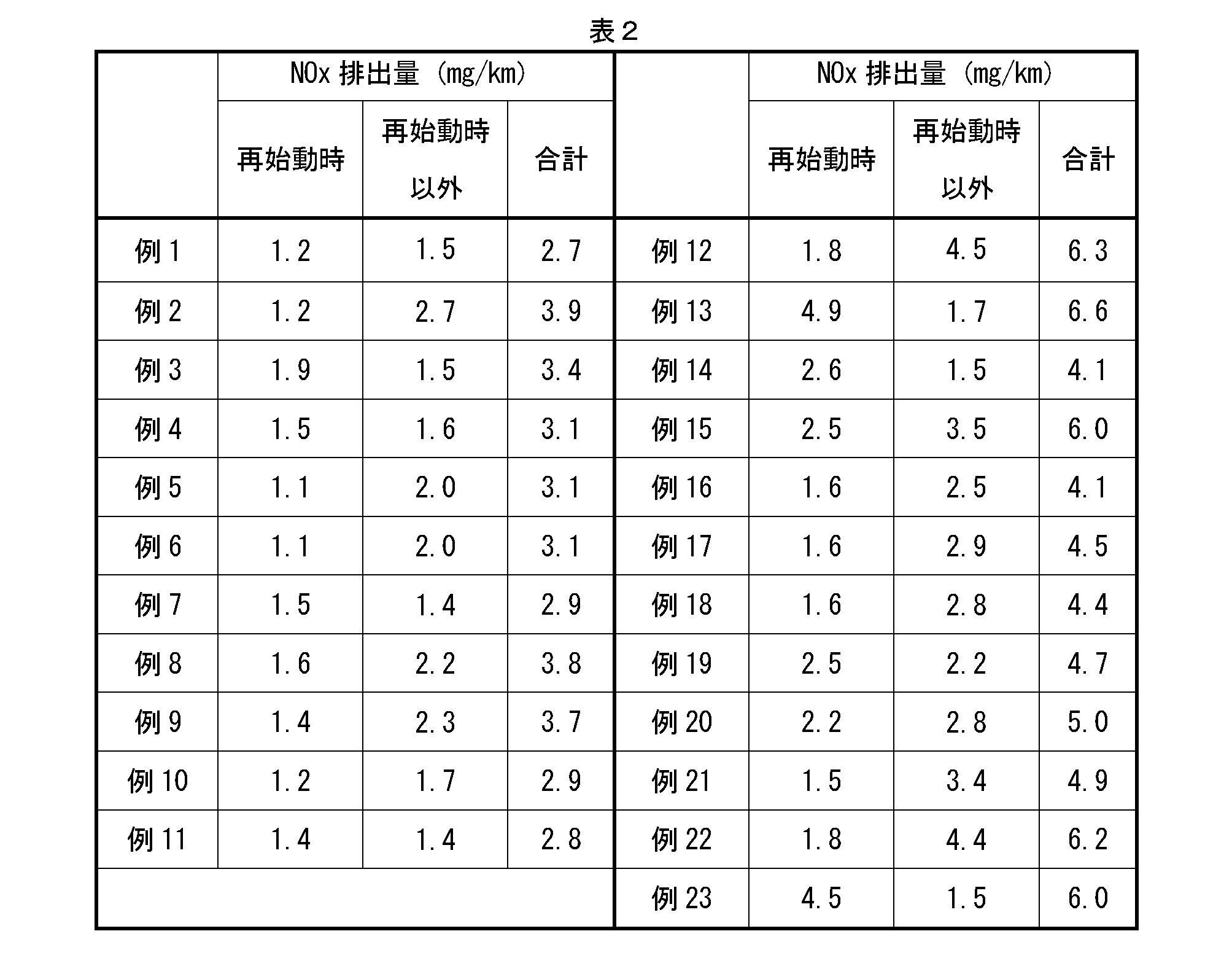
表2に示すように、例えば例1~11では、触媒容積1Lあたりの触媒コート層のCeO2成分含有量は、10g/L~30g/Lであり、最上コート層上流部のCeO2成分含有量は、最上コート層下流部および下方コート層のそれぞれのCeO2成分含有量よりも少ない。また、最上コート層上流部におけるCeO2成分含有量は、最上コート層下流部におけるCeO2成分含有量の1/100倍~1/2倍である。この場合、合計NOx排出量は、4.0mg/km以下であり、特に、エンジン再始動時のNOx排出量は、2.0mg/km以下である。よって、例1~11において、エンジン再始動時におけるNOx浄化性能が良いことが分かる。しかし、触媒容積1Lあたりの触媒コート層のCeO2成分含有量が10g/L~30g/Lの範囲外である例12および13では、合計NOx排出量が6.0mg/kmを超えている。特に、触媒容積1Lあたりの触媒コート層のCeO2成分含有量が10g/Lを下回る例12では、エンジン再始動時以外のNOx排出量が多くなっている。これは、触媒コート層におけるCeO2成分含有量が少ないため、通常走行時のNOx浄化性能が低くなったためだと考えられる。
2 内燃機関(エンジン)
3 エキゾーストマニホールド
4 排気管
5 ECU
7、7A 排ガス浄化用触媒
8 圧力センサ
10 基材(多孔質基材)
12 セル
16 隔壁
30、30A 触媒コート層
40、40A 下方コート層
40a 最下コート層
40b 中間コート層
50 最上コート層
51 最上コート層上流部
52 最上コート層下流部
Claims (6)
- 内燃機関の排気通路に配置され、該内燃機関から排出される排ガスを浄化する排ガス浄化用触媒であって、
多孔質基材と、該多孔質基材上に形成された触媒コート層と、を備え、
前記触媒コート層は、担体と、該担体に担持されている貴金属触媒と、を有し、
前記担体は、少なくともCeO2成分を含むOSC材を備え、
前記触媒コート層は、厚み方向に少なくとも2層の相互に構成が異なる複数のコート層によって構成されており、ここで、
前記複数のコート層のうちの最表部に位置する最上層である最上コート層において、
前記最上コート層の排ガス流動方向に沿う全体長に対して、排ガス入口側の端部から少なくとも20%を包含する最上コート層上流部における前記CeO2成分含有量は、前記最上コート層の排ガス流動方向に沿う全体長に対して、排ガス出口側の端部から少なくとも20%を包含する最上コート層下流部における前記CeO2成分含有量よりも少なく、かつ、
前記最上コート層上流部における前記CeO2成分含有量は、前記複数のコート層のうちの前記最上コート層よりも前記多孔質基材に近い下方コート層における前記CeO2成分含有量よりも少なく、
触媒容積1Lあたりの前記触媒コート層全体における前記CeO2成分含有量は、10~30g/Lである、排ガス浄化用触媒。 - 前記最上コート層上流部における前記CeO2成分含有量は、前記最上コート層下流部における前記CeO2成分含有量の1/100倍~1/2倍である、請求項1に記載の排ガス浄化用触媒。
- 触媒容積1Lあたりの前記最上コート層上流部における前記CeO2成分含有量は、0.1~2g/Lである、請求項1または2に記載された排ガス浄化用触媒。
- 前記最上コート層の排ガス流動方向の全体長を100として、前記最上コート層上流部の前記排ガス流動方向に沿う長さと、前記最上コート層下流部の前記排ガス流動方向に沿う長さとの比率(上流部/下流部)は、20/80~75/25である、請求項1から3までの何れか一つに記載された排ガス浄化用触媒。
- 前記貴金属触媒は、Pt、PdおよびRhのうちの少なくとも一種である、請求項1から4までの何れか一つに記載された排ガス浄化用触媒。
- 前記最上コート層は、前記貴金属触媒としてPdおよびRhを含む、請求項5に記載された排ガス浄化用触媒。
Priority Applications (4)
| Application Number | Priority Date | Filing Date | Title |
|---|---|---|---|
| JP2015552457A JP6487851B2 (ja) | 2013-12-13 | 2014-12-09 | 排ガス浄化用触媒 |
| CN201480049425.XA CN105517705B (zh) | 2013-12-13 | 2014-12-09 | 排气净化用催化剂 |
| EP14870329.1A EP3034166B1 (en) | 2013-12-13 | 2014-12-09 | Exhaust gas purification catalyst |
| US14/914,299 US9694348B2 (en) | 2013-12-13 | 2014-12-09 | Exhaust cleaning catalyst |
Applications Claiming Priority (2)
| Application Number | Priority Date | Filing Date | Title |
|---|---|---|---|
| JP2013-258650 | 2013-12-13 | ||
| JP2013258650 | 2013-12-13 |
Publications (1)
| Publication Number | Publication Date |
|---|---|
| WO2015087871A1 true WO2015087871A1 (ja) | 2015-06-18 |
Family
ID=53371173
Family Applications (1)
| Application Number | Title | Priority Date | Filing Date |
|---|---|---|---|
| PCT/JP2014/082539 Ceased WO2015087871A1 (ja) | 2013-12-13 | 2014-12-09 | 排ガス浄化用触媒 |
Country Status (5)
| Country | Link |
|---|---|
| US (1) | US9694348B2 (ja) |
| EP (1) | EP3034166B1 (ja) |
| JP (1) | JP6487851B2 (ja) |
| CN (1) | CN105517705B (ja) |
| WO (1) | WO2015087871A1 (ja) |
Cited By (12)
| Publication number | Priority date | Publication date | Assignee | Title |
|---|---|---|---|---|
| JPWO2015087872A1 (ja) * | 2013-12-13 | 2017-03-16 | 株式会社キャタラー | 排ガス浄化用触媒 |
| EP3241614A1 (en) * | 2016-05-02 | 2017-11-08 | Mitsubishi Jidosha Kogyo K.K. | Exhaust gas purification catalyst for internal combustion engine |
| EP3241613A1 (en) * | 2016-05-02 | 2017-11-08 | Mitsubishi Jidosha Kogyo Kabushiki Kaisha | Exhaust gas purification catalyst for internal combustion engine |
| WO2017204008A1 (ja) * | 2016-05-24 | 2017-11-30 | 株式会社キャタラー | 排ガス浄化用触媒 |
| JP2017217590A (ja) * | 2016-06-06 | 2017-12-14 | 株式会社Soken | 排ガス浄化用触媒の製造方法 |
| WO2018199250A1 (ja) * | 2017-04-28 | 2018-11-01 | ユミコア日本触媒株式会社 | 排気ガス浄化用触媒およびそれを用いた排気ガス浄化方法 |
| EP3471877A4 (en) * | 2016-06-17 | 2020-07-29 | BASF Corporation | DIESEL OXIDATION CATALYST WITH PALLADIUM |
| JP2020131060A (ja) * | 2019-02-13 | 2020-08-31 | 三菱自動車工業株式会社 | 内燃機関の排気浄化触媒 |
| WO2023176325A1 (ja) * | 2022-03-14 | 2023-09-21 | 株式会社キャタラー | 排ガス浄化用触媒 |
| JP2023543159A (ja) * | 2020-09-11 | 2023-10-13 | ビーエーエスエフ コーポレーション | 層状触媒物品及び触媒物品の製造方法 |
| JP7696531B1 (ja) * | 2023-12-28 | 2025-06-20 | 三井金属鉱業株式会社 | 排ガス浄化用触媒 |
| WO2025142859A1 (ja) * | 2023-12-28 | 2025-07-03 | 三井金属鉱業株式会社 | 排ガス浄化用触媒 |
Families Citing this family (13)
| Publication number | Priority date | Publication date | Assignee | Title |
|---|---|---|---|---|
| JP6716067B2 (ja) * | 2014-08-19 | 2020-07-01 | ヤンマーパワーテクノロジー株式会社 | ディーゼル用酸化触媒 |
| US20180280878A1 (en) * | 2015-09-24 | 2018-10-04 | Cataler Corporation | Catalyst for exhaust gas purification, method for producing same and exhaust gas purification apparatus comprising said catalyst |
| WO2017159628A1 (ja) * | 2016-03-18 | 2017-09-21 | 株式会社キャタラー | 排ガス浄化用触媒 |
| JP6346642B2 (ja) * | 2016-09-26 | 2018-06-20 | 株式会社キャタラー | 排ガス浄化用触媒 |
| CN111741813B (zh) | 2018-02-21 | 2023-08-04 | 株式会社科特拉 | 排气净化催化剂装置 |
| CN111741812A (zh) * | 2018-02-21 | 2020-10-02 | 株式会社科特拉 | 排气净化催化剂装置 |
| JP7245613B2 (ja) * | 2018-07-05 | 2023-03-24 | 株式会社キャタラー | 排ガス浄化触媒装置 |
| CN109261220A (zh) * | 2018-09-28 | 2019-01-25 | 昆明贵研催化剂有限责任公司 | 一种非均匀涂覆尾气净化催化剂的制备方法及应用 |
| JP7288331B2 (ja) * | 2019-03-29 | 2023-06-07 | 株式会社キャタラー | 排ガス浄化触媒装置 |
| KR102211944B1 (ko) * | 2019-04-04 | 2021-02-03 | 희성촉매 주식회사 | 귀금속 박층을 최상층으로 포함하는 다층구조의 배기가스 정화용 촉매 및 이의 제조방법 |
| JP7386651B2 (ja) * | 2019-09-02 | 2023-11-27 | 株式会社キャタラー | 排ガス浄化用触媒 |
| JP6980061B1 (ja) * | 2020-06-26 | 2021-12-15 | 株式会社キャタラー | 排ガス浄化用触媒 |
| CN115920884B (zh) * | 2022-11-03 | 2024-05-17 | 无锡威孚环保催化剂有限公司 | 一种降低thc排放的三效催化剂及其制备方法 |
Citations (6)
| Publication number | Priority date | Publication date | Assignee | Title |
|---|---|---|---|---|
| JP2007021456A (ja) * | 2005-07-21 | 2007-02-01 | Cataler Corp | 排ガス浄化用触媒 |
| JP2010029752A (ja) * | 2008-07-25 | 2010-02-12 | Ne Chemcat Corp | 排気ガス浄化触媒装置、並びに排気ガス浄化方法 |
| JP2011212639A (ja) | 2010-04-02 | 2011-10-27 | Toyota Motor Corp | 自動車排ガス浄化用触媒 |
| JP2012020276A (ja) * | 2010-01-04 | 2012-02-02 | Toyota Motor Corp | 排ガス浄化用触媒 |
| JP2012040547A (ja) | 2010-07-23 | 2012-03-01 | Toyota Motor Corp | 排ガス浄化用触媒 |
| WO2012069405A1 (en) * | 2010-11-22 | 2012-05-31 | Umicore Ag & Co. Kg | Three-way catalytic system having an upstream multi - layer catalyst |
Family Cites Families (17)
| Publication number | Priority date | Publication date | Assignee | Title |
|---|---|---|---|---|
| DE69435061T2 (de) * | 1993-06-25 | 2008-12-18 | Basf Catalysts Llc | Katalysatorzusammensetzung |
| JP3235640B2 (ja) * | 1995-11-09 | 2001-12-04 | 株式会社アイシーティー | 内燃機関排ガス浄化用触媒 |
| CN1205652A (zh) * | 1995-12-21 | 1999-01-20 | 恩格尔哈德公司 | 发动机废气处理装置及应用方法 |
| US6087298A (en) * | 1996-05-14 | 2000-07-11 | Engelhard Corporation | Exhaust gas treatment system |
| US20030175192A1 (en) * | 2001-01-26 | 2003-09-18 | Engelhard Corporation | SOx trap for enhancing NOx trap performance and methods of making and using the same |
| US6777370B2 (en) * | 2001-04-13 | 2004-08-17 | Engelhard Corporation | SOx tolerant NOx trap catalysts and methods of making and using the same |
| US6764665B2 (en) * | 2001-10-26 | 2004-07-20 | Engelhard Corporation | Layered catalyst composite |
| US7795172B2 (en) * | 2004-06-22 | 2010-09-14 | Basf Corporation | Layered exhaust treatment catalyst |
| US7550124B2 (en) * | 2006-08-21 | 2009-06-23 | Basf Catalysts Llc | Layered catalyst composite |
| US20080044330A1 (en) * | 2006-08-21 | 2008-02-21 | Shau-Lin Franklin Chen | Layered catalyst composite |
| US7758834B2 (en) * | 2006-08-21 | 2010-07-20 | Basf Corporation | Layered catalyst composite |
| US7517510B2 (en) * | 2006-08-21 | 2009-04-14 | Basf Catalysts Llc | Layered catalyst composite |
| EP2127744B1 (en) * | 2007-02-01 | 2018-07-18 | Daiichi Kigenso Kagaku Kogyo Co., Ltd. | Exhaust gas purification apparatus comprising a catalyst system and exhaust gas purification method |
| US10773209B2 (en) * | 2009-02-20 | 2020-09-15 | Basf Corporation | Aging-resistant catalyst article for internal combustion engines |
| JP5240275B2 (ja) * | 2010-10-22 | 2013-07-17 | トヨタ自動車株式会社 | 排ガス浄化用触媒 |
| US8617496B2 (en) * | 2011-01-19 | 2013-12-31 | Basf Corporation | Three way conversion catalyst with alumina-free rhodium layer |
| JP5870981B2 (ja) * | 2013-10-09 | 2016-03-01 | トヨタ自動車株式会社 | 触媒コンバーター |
-
2014
- 2014-12-09 CN CN201480049425.XA patent/CN105517705B/zh active Active
- 2014-12-09 US US14/914,299 patent/US9694348B2/en active Active
- 2014-12-09 WO PCT/JP2014/082539 patent/WO2015087871A1/ja not_active Ceased
- 2014-12-09 JP JP2015552457A patent/JP6487851B2/ja active Active
- 2014-12-09 EP EP14870329.1A patent/EP3034166B1/en active Active
Patent Citations (6)
| Publication number | Priority date | Publication date | Assignee | Title |
|---|---|---|---|---|
| JP2007021456A (ja) * | 2005-07-21 | 2007-02-01 | Cataler Corp | 排ガス浄化用触媒 |
| JP2010029752A (ja) * | 2008-07-25 | 2010-02-12 | Ne Chemcat Corp | 排気ガス浄化触媒装置、並びに排気ガス浄化方法 |
| JP2012020276A (ja) * | 2010-01-04 | 2012-02-02 | Toyota Motor Corp | 排ガス浄化用触媒 |
| JP2011212639A (ja) | 2010-04-02 | 2011-10-27 | Toyota Motor Corp | 自動車排ガス浄化用触媒 |
| JP2012040547A (ja) | 2010-07-23 | 2012-03-01 | Toyota Motor Corp | 排ガス浄化用触媒 |
| WO2012069405A1 (en) * | 2010-11-22 | 2012-05-31 | Umicore Ag & Co. Kg | Three-way catalytic system having an upstream multi - layer catalyst |
Cited By (23)
| Publication number | Priority date | Publication date | Assignee | Title |
|---|---|---|---|---|
| JPWO2015087872A1 (ja) * | 2013-12-13 | 2017-03-16 | 株式会社キャタラー | 排ガス浄化用触媒 |
| EP3241614A1 (en) * | 2016-05-02 | 2017-11-08 | Mitsubishi Jidosha Kogyo K.K. | Exhaust gas purification catalyst for internal combustion engine |
| EP3241613A1 (en) * | 2016-05-02 | 2017-11-08 | Mitsubishi Jidosha Kogyo Kabushiki Kaisha | Exhaust gas purification catalyst for internal combustion engine |
| JP2017200675A (ja) * | 2016-05-02 | 2017-11-09 | 三菱自動車工業株式会社 | 内燃機関の排ガス浄化触媒 |
| JP2017200676A (ja) * | 2016-05-02 | 2017-11-09 | 三菱自動車工業株式会社 | 内燃機関の排ガス浄化触媒 |
| US10213741B2 (en) | 2016-05-02 | 2019-02-26 | Mitsubishi Jidosha Kogyo Kabushiki Kaisha | Exhaust gas purification catalyst for internal combustion engine |
| US10960389B2 (en) | 2016-05-24 | 2021-03-30 | Cataler Corporation | Exhaust gas purification catalyst |
| WO2017204008A1 (ja) * | 2016-05-24 | 2017-11-30 | 株式会社キャタラー | 排ガス浄化用触媒 |
| JPWO2017204008A1 (ja) * | 2016-05-24 | 2019-03-22 | 株式会社キャタラー | 排ガス浄化用触媒 |
| JP2017217590A (ja) * | 2016-06-06 | 2017-12-14 | 株式会社Soken | 排ガス浄化用触媒の製造方法 |
| US11248505B2 (en) | 2016-06-17 | 2022-02-15 | Basf Corporation | Palladium diesel oxidation catalyst |
| EP3471877A4 (en) * | 2016-06-17 | 2020-07-29 | BASF Corporation | DIESEL OXIDATION CATALYST WITH PALLADIUM |
| JPWO2018199250A1 (ja) * | 2017-04-28 | 2020-03-12 | ユミコア日本触媒株式会社 | 排気ガス浄化用触媒およびそれを用いた排気ガス浄化方法 |
| US11141713B2 (en) | 2017-04-28 | 2021-10-12 | Umicore Shokubai Japan Co., Ltd. | Exhaust gas purification catalyst and exhaust gas purification method using the same |
| WO2018199250A1 (ja) * | 2017-04-28 | 2018-11-01 | ユミコア日本触媒株式会社 | 排気ガス浄化用触媒およびそれを用いた排気ガス浄化方法 |
| JP2020131060A (ja) * | 2019-02-13 | 2020-08-31 | 三菱自動車工業株式会社 | 内燃機関の排気浄化触媒 |
| JP7335543B2 (ja) | 2019-02-13 | 2023-08-30 | 三菱自動車工業株式会社 | 内燃機関の排気浄化触媒 |
| JP2023543159A (ja) * | 2020-09-11 | 2023-10-13 | ビーエーエスエフ コーポレーション | 層状触媒物品及び触媒物品の製造方法 |
| JP7837325B2 (ja) | 2020-09-11 | 2026-03-30 | ビーエーエスエフ モバイル エミッションズ カタリスツ エルエルシー | 層状触媒物品及び触媒物品の製造方法 |
| WO2023176325A1 (ja) * | 2022-03-14 | 2023-09-21 | 株式会社キャタラー | 排ガス浄化用触媒 |
| JP2023134093A (ja) * | 2022-03-14 | 2023-09-27 | 株式会社キャタラー | 排ガス浄化用触媒 |
| JP7696531B1 (ja) * | 2023-12-28 | 2025-06-20 | 三井金属鉱業株式会社 | 排ガス浄化用触媒 |
| WO2025142859A1 (ja) * | 2023-12-28 | 2025-07-03 | 三井金属鉱業株式会社 | 排ガス浄化用触媒 |
Also Published As
| Publication number | Publication date |
|---|---|
| JPWO2015087871A1 (ja) | 2017-03-16 |
| EP3034166A4 (en) | 2017-05-03 |
| JP6487851B2 (ja) | 2019-03-20 |
| CN105517705B (zh) | 2018-09-14 |
| US9694348B2 (en) | 2017-07-04 |
| EP3034166A1 (en) | 2016-06-22 |
| EP3034166B1 (en) | 2020-10-07 |
| US20160199815A1 (en) | 2016-07-14 |
| CN105517705A (zh) | 2016-04-20 |
Similar Documents
| Publication | Publication Date | Title |
|---|---|---|
| JP6487851B2 (ja) | 排ガス浄化用触媒 | |
| JP6611611B2 (ja) | 排ガス浄化用触媒 | |
| JP6964580B2 (ja) | 排ガス浄化用触媒 | |
| JP6353919B2 (ja) | 排ガス浄化用触媒 | |
| US12201965B2 (en) | Exhaust gas purification catalyst | |
| JP6417333B2 (ja) | 排ガス浄化用触媒 | |
| CN108778491B (zh) | 废气净化用催化剂 | |
| WO2016133086A1 (ja) | 排ガス浄化用触媒 | |
| CN107249736A (zh) | 排气净化用催化剂 | |
| WO2019012874A1 (ja) | 排ガス浄化用触媒 | |
| WO2016039302A1 (ja) | 排ガス浄化用触媒 | |
| US20220154621A1 (en) | Exhaust Gas Purification Catalyst | |
| CN112236228A (zh) | 排气净化催化剂装置 |
Legal Events
| Date | Code | Title | Description |
|---|---|---|---|
| 121 | Ep: the epo has been informed by wipo that ep was designated in this application |
Ref document number: 14870329 Country of ref document: EP Kind code of ref document: A1 |
|
| WWE | Wipo information: entry into national phase |
Ref document number: 14914299 Country of ref document: US |
|
| ENP | Entry into the national phase |
Ref document number: 2015552457 Country of ref document: JP Kind code of ref document: A |
|
| WWE | Wipo information: entry into national phase |
Ref document number: 2014870329 Country of ref document: EP |
|
| NENP | Non-entry into the national phase |
Ref country code: DE |