WO2015087930A1 - 調節眼内レンズ - Google Patents
調節眼内レンズ Download PDFInfo
- Publication number
- WO2015087930A1 WO2015087930A1 PCT/JP2014/082735 JP2014082735W WO2015087930A1 WO 2015087930 A1 WO2015087930 A1 WO 2015087930A1 JP 2014082735 W JP2014082735 W JP 2014082735W WO 2015087930 A1 WO2015087930 A1 WO 2015087930A1
- Authority
- WO
- WIPO (PCT)
- Prior art keywords
- optical
- intraocular lens
- capsule
- lens
- support portion
- Prior art date
- Legal status (The legal status is an assumption and is not a legal conclusion. Google has not performed a legal analysis and makes no representation as to the accuracy of the status listed.)
- Ceased
Links
Images




Classifications
-
- A—HUMAN NECESSITIES
- A61—MEDICAL OR VETERINARY SCIENCE; HYGIENE
- A61F—FILTERS IMPLANTABLE INTO BLOOD VESSELS; PROSTHESES; DEVICES PROVIDING PATENCY TO, OR PREVENTING COLLAPSING OF, TUBULAR STRUCTURES OF THE BODY, e.g. STENTS; ORTHOPAEDIC, NURSING OR CONTRACEPTIVE DEVICES; FOMENTATION; TREATMENT OR PROTECTION OF EYES OR EARS; BANDAGES, DRESSINGS OR ABSORBENT PADS; FIRST-AID KITS
- A61F2/00—Filters implantable into blood vessels; Prostheses, i.e. artificial substitutes or replacements for parts of the body; Appliances for connecting them with the body; Devices providing patency to, or preventing collapsing of, tubular structures of the body, e.g. stents
- A61F2/02—Prostheses implantable into the body
- A61F2/14—Eye parts, e.g. lenses or corneal implants; Artificial eyes
- A61F2/16—Intraocular lenses
- A61F2/1613—Intraocular lenses having special lens configurations, e.g. multipart lenses; having particular optical properties, e.g. pseudo-accommodative lenses, lenses having aberration corrections, diffractive lenses, lenses for variably absorbing electromagnetic radiation, lenses having variable focus
- A61F2/1624—Intraocular lenses having special lens configurations, e.g. multipart lenses; having particular optical properties, e.g. pseudo-accommodative lenses, lenses having aberration corrections, diffractive lenses, lenses for variably absorbing electromagnetic radiation, lenses having variable focus having adjustable focus; power activated variable focus means, e.g. mechanically or electrically by the ciliary muscle or from the outside
- A61F2/1635—Intraocular lenses having special lens configurations, e.g. multipart lenses; having particular optical properties, e.g. pseudo-accommodative lenses, lenses having aberration corrections, diffractive lenses, lenses for variably absorbing electromagnetic radiation, lenses having variable focus having adjustable focus; power activated variable focus means, e.g. mechanically or electrically by the ciliary muscle or from the outside for changing shape
-
- A—HUMAN NECESSITIES
- A61—MEDICAL OR VETERINARY SCIENCE; HYGIENE
- A61F—FILTERS IMPLANTABLE INTO BLOOD VESSELS; PROSTHESES; DEVICES PROVIDING PATENCY TO, OR PREVENTING COLLAPSING OF, TUBULAR STRUCTURES OF THE BODY, e.g. STENTS; ORTHOPAEDIC, NURSING OR CONTRACEPTIVE DEVICES; FOMENTATION; TREATMENT OR PROTECTION OF EYES OR EARS; BANDAGES, DRESSINGS OR ABSORBENT PADS; FIRST-AID KITS
- A61F2/00—Filters implantable into blood vessels; Prostheses, i.e. artificial substitutes or replacements for parts of the body; Appliances for connecting them with the body; Devices providing patency to, or preventing collapsing of, tubular structures of the body, e.g. stents
- A61F2/02—Prostheses implantable into the body
- A61F2/14—Eye parts, e.g. lenses or corneal implants; Artificial eyes
- A61F2/16—Intraocular lenses
- A61F2/16015—Lens having spacers for providing a gap between the posterior capsule and a posterior surface of the intraocular lens
-
- A—HUMAN NECESSITIES
- A61—MEDICAL OR VETERINARY SCIENCE; HYGIENE
- A61F—FILTERS IMPLANTABLE INTO BLOOD VESSELS; PROSTHESES; DEVICES PROVIDING PATENCY TO, OR PREVENTING COLLAPSING OF, TUBULAR STRUCTURES OF THE BODY, e.g. STENTS; ORTHOPAEDIC, NURSING OR CONTRACEPTIVE DEVICES; FOMENTATION; TREATMENT OR PROTECTION OF EYES OR EARS; BANDAGES, DRESSINGS OR ABSORBENT PADS; FIRST-AID KITS
- A61F2/00—Filters implantable into blood vessels; Prostheses, i.e. artificial substitutes or replacements for parts of the body; Appliances for connecting them with the body; Devices providing patency to, or preventing collapsing of, tubular structures of the body, e.g. stents
- A61F2/02—Prostheses implantable into the body
- A61F2/14—Eye parts, e.g. lenses or corneal implants; Artificial eyes
- A61F2/16—Intraocular lenses
- A61F2/1613—Intraocular lenses having special lens configurations, e.g. multipart lenses; having particular optical properties, e.g. pseudo-accommodative lenses, lenses having aberration corrections, diffractive lenses, lenses for variably absorbing electromagnetic radiation, lenses having variable focus
- A61F2/1648—Multipart lenses
-
- A—HUMAN NECESSITIES
- A61—MEDICAL OR VETERINARY SCIENCE; HYGIENE
- A61F—FILTERS IMPLANTABLE INTO BLOOD VESSELS; PROSTHESES; DEVICES PROVIDING PATENCY TO, OR PREVENTING COLLAPSING OF, TUBULAR STRUCTURES OF THE BODY, e.g. STENTS; ORTHOPAEDIC, NURSING OR CONTRACEPTIVE DEVICES; FOMENTATION; TREATMENT OR PROTECTION OF EYES OR EARS; BANDAGES, DRESSINGS OR ABSORBENT PADS; FIRST-AID KITS
- A61F2/00—Filters implantable into blood vessels; Prostheses, i.e. artificial substitutes or replacements for parts of the body; Appliances for connecting them with the body; Devices providing patency to, or preventing collapsing of, tubular structures of the body, e.g. stents
- A61F2/02—Prostheses implantable into the body
- A61F2/14—Eye parts, e.g. lenses or corneal implants; Artificial eyes
- A61F2/16—Intraocular lenses
- A61F2/1694—Capsular bag spreaders therefor
-
- A—HUMAN NECESSITIES
- A61—MEDICAL OR VETERINARY SCIENCE; HYGIENE
- A61F—FILTERS IMPLANTABLE INTO BLOOD VESSELS; PROSTHESES; DEVICES PROVIDING PATENCY TO, OR PREVENTING COLLAPSING OF, TUBULAR STRUCTURES OF THE BODY, e.g. STENTS; ORTHOPAEDIC, NURSING OR CONTRACEPTIVE DEVICES; FOMENTATION; TREATMENT OR PROTECTION OF EYES OR EARS; BANDAGES, DRESSINGS OR ABSORBENT PADS; FIRST-AID KITS
- A61F2/00—Filters implantable into blood vessels; Prostheses, i.e. artificial substitutes or replacements for parts of the body; Appliances for connecting them with the body; Devices providing patency to, or preventing collapsing of, tubular structures of the body, e.g. stents
- A61F2/02—Prostheses implantable into the body
- A61F2/14—Eye parts, e.g. lenses or corneal implants; Artificial eyes
- A61F2/16—Intraocular lenses
- A61F2/1613—Intraocular lenses having special lens configurations, e.g. multipart lenses; having particular optical properties, e.g. pseudo-accommodative lenses, lenses having aberration corrections, diffractive lenses, lenses for variably absorbing electromagnetic radiation, lenses having variable focus
- A61F2/1624—Intraocular lenses having special lens configurations, e.g. multipart lenses; having particular optical properties, e.g. pseudo-accommodative lenses, lenses having aberration corrections, diffractive lenses, lenses for variably absorbing electromagnetic radiation, lenses having variable focus having adjustable focus; power activated variable focus means, e.g. mechanically or electrically by the ciliary muscle or from the outside
- A61F2/1627—Intraocular lenses having special lens configurations, e.g. multipart lenses; having particular optical properties, e.g. pseudo-accommodative lenses, lenses having aberration corrections, diffractive lenses, lenses for variably absorbing electromagnetic radiation, lenses having variable focus having adjustable focus; power activated variable focus means, e.g. mechanically or electrically by the ciliary muscle or from the outside for changing index of refraction, e.g. by external means or by tilting
-
- A—HUMAN NECESSITIES
- A61—MEDICAL OR VETERINARY SCIENCE; HYGIENE
- A61F—FILTERS IMPLANTABLE INTO BLOOD VESSELS; PROSTHESES; DEVICES PROVIDING PATENCY TO, OR PREVENTING COLLAPSING OF, TUBULAR STRUCTURES OF THE BODY, e.g. STENTS; ORTHOPAEDIC, NURSING OR CONTRACEPTIVE DEVICES; FOMENTATION; TREATMENT OR PROTECTION OF EYES OR EARS; BANDAGES, DRESSINGS OR ABSORBENT PADS; FIRST-AID KITS
- A61F2/00—Filters implantable into blood vessels; Prostheses, i.e. artificial substitutes or replacements for parts of the body; Appliances for connecting them with the body; Devices providing patency to, or preventing collapsing of, tubular structures of the body, e.g. stents
- A61F2/02—Prostheses implantable into the body
- A61F2/14—Eye parts, e.g. lenses or corneal implants; Artificial eyes
- A61F2/16—Intraocular lenses
- A61F2002/1681—Intraocular lenses having supporting structure for lens, e.g. haptics
- A61F2002/1682—Intraocular lenses having supporting structure for lens, e.g. haptics having mechanical force transfer mechanism to the lens, e.g. for accommodating lenses
-
- A—HUMAN NECESSITIES
- A61—MEDICAL OR VETERINARY SCIENCE; HYGIENE
- A61F—FILTERS IMPLANTABLE INTO BLOOD VESSELS; PROSTHESES; DEVICES PROVIDING PATENCY TO, OR PREVENTING COLLAPSING OF, TUBULAR STRUCTURES OF THE BODY, e.g. STENTS; ORTHOPAEDIC, NURSING OR CONTRACEPTIVE DEVICES; FOMENTATION; TREATMENT OR PROTECTION OF EYES OR EARS; BANDAGES, DRESSINGS OR ABSORBENT PADS; FIRST-AID KITS
- A61F2250/00—Special features of prostheses classified in groups A61F2/00 - A61F2/26 or A61F2/82 or A61F9/00 or A61F11/00 or subgroups thereof
- A61F2250/0003—Special features of prostheses classified in groups A61F2/00 - A61F2/26 or A61F2/82 or A61F9/00 or A61F11/00 or subgroups thereof having an inflatable pocket filled with fluid, e.g. liquid or gas
Definitions
- the present invention relates to an adjusting intraocular lens that is inserted into an anterior capsulotomy lens capsule in ophthalmic surgery such as cataract surgery, refractive surgery, or presbyopia surgery.
- the crystalline lens L is a transparent lens that has a convex lens shape with a diameter of about 9 to 10 mm and a thickness of about 4 to 5 mm. It is fixed to the ciliary body C via the chin zonule Z in a manner located behind the iris I.
- the ciliary muscle Cm of the ciliary body C contracts and the ciliary body C becomes centripetal (in the direction of the lens equator Se) as shown in FIG. ) And the ciliary body C is positioned in the direction of approaching the capsular bag S.
- the tension of the chin strap Z is weakened, and the thickness of the crystalline lens L is increased due to the inherent elasticity of the crystalline lens L, thereby performing focus adjustment during near vision.
- this focus adjustment it is known that the closer to the center of the anterior lens capsule Sf, the better, and the posterior lens capsule Sb hardly moves.
- accommodation power distance to near vision
- the disease that occurs in the above-mentioned lens includes a disease called cataract that is mainly clouded due to aging, and many patients undergo cataract surgery to treat this cataract.
- a circular hole is usually created by circular incision of the anterior capsule, and the contents of the turbid lens are removed by ultrasonic lens emulsification and suction.
- a transparent lens with a circular hole is then removed.
- a method of inserting an intraocular lens into the lens capsule while leaving only the capsule is applied. Cataract surgery using this method is currently performed on over 1 million patients annually in Japan, and over 3 million patients annually in the United States, and intraocular lenses used here are generally single-focus lenses. It was.
- single focus lenses are generally made of PMMA (Poly Methyl Methacrylate), silicon, acrylic, etc., and the thickness of the single focus lens itself cannot be changed. The loss of power could not be avoided.
- a refracting multifocal lens provided with a concentric part having different refractive power in the optical part, or a diffractive multifocal lens provided with a structure in which an optical diffraction phenomenon occurs in the optical part is used for far vision
- a multifocal lens that disperses and enters light entering the eye is known for near vision (some types have intermediate vision).
- these multifocal intraocular lenses sufficiently satisfy the patient's requirements, such as the occurrence of glare that looks like a halo or glare that shines in a ring of light, and poor vision or contrast sensitivity. It was not reached.
- the optical unit comprising a convex lens and two articulated connecting arms provided in contact with the inner side of the crystalline lens equator are provided to perform the adjustment function in a manner different from that described above.
- An adjusting intraocular lens that adjusts by moving the optical unit back and forth is known (see Patent Document 1 below).
- the connecting arm is attached to the optical unit at the first position on the connecting arm, and at the second position on the connecting arm, the ciliary muscle contraction The relaxation cooperates with the movement of the equator of the capsular bag, which is transmitted through the chin band.
- Capsular Tensions Ring (Crystal Sac Expansion Ring), which is an open ring formed in a C shape. This ring is inserted from the inside into the equator of the lens where the chin ligament is weak or torn. Then, the lens equator is expanded outward and the shape is rounded.
- the other is an equatorial ring called an equatorial ring, which is formed in an O-shape and has a slightly thicker closed ring (connected ring) with a sharp edge such as a square cross section.
- This ring is placed inside the lens equator to create a strong bend in the lens capsule and to prevent lens epithelial cells from proliferating inward.
- the focus adjustment function in the human eye is expressed based on contraction and relaxation by the ciliary muscles of the ciliary body, and the optical part of the adjusting intraocular lens can be moved back and forth. Therefore, it is necessary to accurately transmit slight contraction / relaxation of the ciliary muscle of the ciliary body to deform the lens capsule. To do so, the chin glands for transmitting ciliary muscle contraction and relaxation to the capsular bag have a moderately strong tension that results in the capsular bag having a moderate tension. It is important to have
- the conventional accommodating intraocular lens does not act so that the chin zonules have a moderately strong tension, so there is little contraction and relaxation by the ciliary muscles of the ciliary body.
- the problem is that it is not accurately transmitted to the capsular bag, it is difficult to accurately convert the optical part to the movement in the front-rear direction, and consequently the adjustment function of the intraocular lens installed inside cannot be expressed accurately. was there.
- the ring-shaped lens capsule expansion device can adjust the position of the lens equator and form a strong bend in the lens capsule. Rather, it works rather in the direction of expanding the equator of the lens outward and weakening the tension of the chin band. For this reason, slight contraction and relaxation of the ciliary muscles of the ciliary body are not accurately transmitted to the lens capsule, and the adjusting function of the adjusting intraocular lens cannot be expressed with high accuracy.
- the present invention has been made in view of the above-described problems, and provides an adjustable intraocular lens capable of accurately and sufficiently exerting a focus adjustment force and preventing the occurrence of secondary cataract. With the goal.
- An accommodating intraocular lens according to the present invention is an accommodating intraocular lens that is inserted into a capsular bag from which contents have been removed in a cataract surgery or the like, in order to achieve the above object, and the capsular bag expansion device, elastic deformation
- the lens capsule expansion device is provided in a manner in contact with the inner surface of the anterior capsule, and a front support portion that allows light to pass to the rear side, and the front support portion on the rear side of the front support portion.
- a rear support part that is in contact with the inner surface of the posterior capsule while facing the rear part, and that has a urging force in a direction in which the front support part and the rear support part are separated from each other.
- a connecting portion that connects the front support portion and the rear support portion, and the urging force of the connection portion causes the front support portion to press the inner surface of the anterior capsule and the posterior support portion of the posterior capsule.
- Inside The optical part is directly or indirectly locked to the connecting part in a form surrounded by the connecting part of the capsular bag expansion device, and the front support part and the rear support part are moved by the movement of the capsular bag. According to the movement of the connecting part when moving in the direction of approaching and separating parts, a force is applied directly or indirectly from the connecting part to change the curvature of the optical part.
- the front support part presses the inner surface of the anterior capsule by the urging force of the connecting part and the rear support part presses the inner surface of the posterior capsule, so that the peripheral part of the crystalline lens equator extends and expands in the front-rear direction.
- the lens equator expands, the lens equator moves centripetally and the diameter of the lens equator shrinks.
- the chin zonule is pulled in both directions on the capsular bag side and the ciliary body side, and a moderately strong tension is continuously applied to the chin zonule, and as a result, an appropriate tension is applied to the capsular bag.
- the Chin zonule can accurately transmit the slight contraction and relaxation of the ciliary muscles of the ciliary body to the capsular bag, which in turn can accurately express the adjustment function of the internal optical unit. Become.
- the anterior aqueous humor flows from the anterior capsulotomy part into the lens capsule through the front support part and the connecting part, and the lens equator part is Since it is exposed to the anterior aqueous humor and exposed, the proliferation or fibrosis of lens epithelial cells in the lens equator is suppressed, and the occurrence of secondary cataract can be prevented.
- a force is applied directly or indirectly from the connecting part to the optical part according to the movement of the connecting part when the front supporting part and the rear supporting part move in the approaching / separating direction according to the movement of the lens capsule. Acts to change the curvature of the optical part, so that the focus adjustment force can be accurately and sufficiently exhibited.
- a bent portion is formed in the connecting portion so as to bend outwardly in the radial direction of the front support portion and the rear support portion, and the optical portion has a peripheral portion bent at the connection portion.
- the peripheral edge of the optical part is locked directly or indirectly to the part and moved according to the movement of the connecting part when the front support part and the rear support part move in the approaching / separating direction according to the movement of the lens capsule.
- the curvature of the optical part is changed by a force acting on the part directly or indirectly in the radial direction from the connecting part. According to this, since the curvature of the optical part changes due to the force acting on the peripheral part of the optical part directly or indirectly from the connecting part in the radial direction, the focus adjustment force is more accurately and sufficiently exhibited. Can do.
- the capsular bag expansion device is provided with a locking member on the inner side of the bent portion of the connecting portion, and the optical portion of the optical portion is locked by a locking member of the bent portion of the connecting portion.
- the peripheral part of the optical part can be reliably locked to the connecting part, and the optical part can be stably arranged inside the lens capsule expanding device.
- the locking member is formed in a U-shape or a V-shape opened radially inward of the optical portion, and is locked with the peripheral portion of the optical portion sandwiched from the front-rear direction. According to this, even if the optical part is made of a soft member that is elastically deformed, the peripheral part of the optical part can be reliably locked.
- the locking member may be formed with a bulging portion that swells inward at the front end portion and / or the rear end portion. According to this, when the peripheral part of the optical part is locked to the locking member, the bulging part of the locking member bulges the central part of the optical part by pressing the peripheral part of the optical part inward, The curvature of the optical part can be changed more effectively.
- the locking member may be locked in such a manner that the peripheral edge of the optical part is pressed from the radial direction. According to this, even if the optical part is made of a relatively hard member that is elastically deformed, the peripheral part of the optical part can be reliably locked.
- the locking member may be formed in a rod shape extending inward in the radial direction of the optical part, and may be locked while pressing the peripheral edge of the optical part inward in the radial direction. According to this, when a force acts directly or indirectly from the connecting portion in the radial direction, the curvature of the optical portion is likely to change.
- the bent portion of the connecting portion may be formed in a U shape or a V shape, and the bent portion may be engaged with the peripheral portion of the optical portion from the front-rear direction. According to this, the peripheral part of the optical part can be reliably locked to the connecting part, and the optical part can be stably disposed inside the lens capsule expanding device.
- the capsular bag expansion device includes a first connecting portion that connects the outer peripheral edge portions of the front supporting portion and the rear supporting portion, and a second connecting portion that connects the inner peripheral edge portions of the front supporting portion and the rear supporting portion.
- the optical part may be directly or indirectly locked to the second connecting part. According to this, since the 1st connection part is provided in the outer-periphery edge part of the said front support part and the said back support part, a chin band and a lens capsule are effective moderately along a lens capsule. Because it can have tension, it can effectively transmit ciliary muscle movement to the capsular bag.
- the second connecting portion is provided at the inner peripheral edge of the front support portion and the rear support portion, so that the opening edge portion near the center of the anterior lens capsule that moves most by the focus adjustment of the eye or its Since the second connecting portion is positioned in the vicinity, the degree of bending greatly changes as the front support portion and the rear support portion move in the front-rear direction, and the second connecting portion changes to the optical portion. A force is easily applied directly or indirectly from the connecting portion, and the curvature of the optical portion can be effectively changed.
- the second connecting portion is formed so that the outward bending is weaker than the first connecting portion, the second connecting portion is accompanied by the movement of the front support portion and the rear support portion in the front-rear direction. Since the degree of bending greatly changes, the bending of the optical part can be changed greatly.
- the optical unit may be provided with a reinforcing member for assisting the deformation of the optical unit. According to this, since the auxiliary member assists the deformation of the optical part, the curvature of the optical part can be effectively changed.
- the reinforcing member is composed of a plurality of U-shaped or V-shaped reinforcing members that can be elastically deformed in the front-rear direction of the optical part, and each of the reinforcing members has a shape in which the peripheral part of the optical part is sandwiched from the front-rear direction. It may be provided at predetermined intervals along the part. According to this, when a force is directly or indirectly applied to the optical part from the connecting part of the lens capsule expansion device, the U-shaped or V-shaped reinforcing member opens or closes, thereby the peripheral edge of the optical part. Since the portion is deformed, the curvature of the optical portion can be effectively changed.
- the reinforcing member further includes a front reinforcing ring member provided on an outer surface in front of the optical unit, and a rear reinforcing ring member provided on an outer surface in the rear of the optical unit, and the front reinforcing ring member
- the rear reinforcing ring member may be connected by a plurality of U-shaped or V-shaped reinforcing members provided at the peripheral edge of the optical unit. According to this, since the peripheral part of the optical part is more reliably deformed by the U-shaped or V-shaped reinforcing member being stably opened or closed, the curvature of the optical part can be changed more effectively. Can do.
- the optical unit may be formed of a stretchable elastic film having a predetermined thickness, and the elastic film may be filled with a fluid substance. According to this, when a force is directly or indirectly applied to the optical part from the connecting part, the optical part is easily deformed, so that the curvature of the optical part can be effectively changed.
- the optical part may be formed such that the peripheral part is formed with a thickness of 20 to 100 ⁇ m, the central part is formed with a thickness of 5 to 20 ⁇ m, and the peripheral part is formed thicker than the central part.
- the optical part is preferably formed so that the elastic film gradually becomes thinner from the peripheral part to the central part. According to this, the peripheral part of the optical part has less local distortion, and the peripheral part is easily deformed uniformly as a whole, and accordingly, the central part of the optical part is also easily deformed uniformly, Since the central part of the part is easily formed by being formed thin, the curvature of the optical part can be effectively changed.
- the optical part may be formed such that portions where the elastic film is thick are formed at predetermined intervals along the peripheral part. According to this, the peripheral part of the optical part has less local distortion, and the peripheral part tends to be uniformly deformed as a whole, and accordingly, the central part of the optical part is also easily deformed uniformly. The curvature of the part can be changed effectively.
- the optical portion may be formed with a bulging portion that swells inward at the front end portion and / or the rear end portion of the thick portion of the elastic film. According to this, when the optical part is deformed, the peripheral part of the optical part is easily constricted in the vicinity of the bulging part, and the central part of the optical part is easily swelled accordingly, so that the curvature of the optical part is effectively increased. Can change.
- the optical part may be formed such that the refractive index of the fluid substance gradually increases toward the central part.
- the optical unit may be formed so as to be partitioned in the front-rear direction, and a refractive index of a partition including the center of the optical unit may be higher than a refractive index of other partitions. According to this, since the refractive index becomes larger as it is closer to the center portion like a human crystalline lens, a large change in the refractive index can be generated by slight deformation of the optical portion.
- the optical part may be provided with a core member that is more rigid than the fluid substance in the central part. According to this, when a force is applied directly or indirectly from the connecting part to the optical part, the fluid substance present around the nuclear substance effectively exerts a force on the elastic film, so that the curvature of the optical part is Can change efficiently.
- the core member may be a convex lens having a refractive power adapted to a patient's case.
- the optical part can be used mainly for the purpose of obtaining adjustment power, and the convex lens provided inside the optical part can be used for the purpose of obtaining a refractive power that matches the patient's symptoms. It is possible to reduce the force refraction error (difference between the target refraction value before surgery and the actual refraction value after surgery).
- the optical unit may be provided with an injection tool for injecting a fluid substance therein.
- an injection tool for injecting a fluid substance therein.
- the lens capsule expanding device may be provided with a convex lens or a concave lens having a refractive power matched to a patient's case on the posterior support portion.
- the elastically deformable optical part can be used mainly for the purpose of obtaining adjustment power, and the convex lens or concave lens provided on the rear support part can be used for the purpose of obtaining refractive power that matches the patient's symptoms. Therefore, the elastically deformable optical part can be easily folded by being formed flat, and can be inserted into the eye from a small incision in the lens capsule.
- the convex lens or concave lens installed in the posterior support part mainly compensates the refractive power after surgery, so the refractive error of refractive power after surgery (the difference between the target refractive value before surgery and the actual refractive value after surgery). ) Can be reduced.
- the front support portion presses the inner surface of the anterior capsule and the rear support portion presses the inner surface of the posterior capsule by the urging force of the connecting portion, so that the peripheral portion of the lens equator extends and expands in the front-rear direction.
- the equator of the lens expands and the equator of the lens moves centripetally, and the diameter of the equator of the lens decreases.
- the chin zonule is pulled in both directions on the capsular bag side and the ciliary body side, and a moderately strong tension is continuously applied to the chin zonule, and as a result, an appropriate tension is applied to the capsular bag.
- the Chin zonule can accurately transmit the slight contraction and relaxation of the ciliary muscles of the ciliary body to the capsular bag, which in turn can accurately express the adjustment function of the internal optical unit.
- the anterior aqueous humor flows from the anterior capsulotomy part into the lens capsule through the front support part and the connecting part, and the lens equator part is Since it is exposed to the anterior aqueous humor and exposed, the proliferation or fibrosis of lens epithelial cells in the lens equator is suppressed, and the occurrence of secondary cataract can be prevented.
- a force is applied directly or indirectly from the connecting part to the optical part according to the movement of the connecting part when the front supporting part and the rear supporting part move in the approaching / separating direction according to the movement of the lens capsule. Acts to change the curvature of the optical part, so that the focus adjustment force can be accurately and sufficiently exhibited.
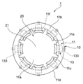
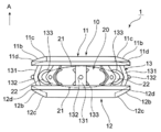
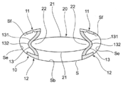
- the accommodation intraocular lens 1 includes a lens capsule expanding device (hereinafter referred to as a device 10) and an optical unit 20 disposed inside the device 10.
- a device lens capsule expanding device
- optical unit 20 disposed inside the device 10.
- the device 10 is installed in a lens capsule S in which an anterior capsule Sf is incised in ophthalmic surgery such as cataract surgery, refractive surgery, or presbyopia surgery. It is what is done.
- the device 10 includes a front support portion 11 located on the front side in the lens capsule S, a rear support portion 12 located on the rear side in the lens capsule S, and the front support portion 11 and the rear. And a connecting portion 13 for connecting the support portion 12.
- the front support portion 11 is an elastic member formed in an annular shape having an opening 11a at the center, as shown in FIGS. As shown in FIG. 3, the front support portion 11 has an inclined surface 11 b that gradually inclines toward the rear side from the inner peripheral edge portion toward the outer peripheral edge portion on the front surface side. For this reason, as shown in FIG. 5, the front support portion 11 is provided in a form in contact with the inner surface of the anterior capsule Sf of the crystalline lens capsule S in a cataract operation or the like, and thus the front support portion 11 is in contact with the anterior capsule Sf. In some cases, the inclined surface 11b can reduce the contact load on the anterior capsule Sf. Moreover, since the front support part 11 consists of an elastic material, it deform
- the front support 11 has a diameter of about 9 to 10 mm and a thickness of about 3.5 to 5.5 mm, and the outer peripheral edge 11d has a diameter of 7.0 mm.
- the diameter of the opening 11a (inner peripheral edge 11c) is 5.0 mm, the width of the inclined surface 11b in contact with the anterior capsule Sf is 1.5 mm, and the thickness is 0.2 to 0.5 mm.
- the front support portion 11 is provided with radial cuts 11e from the inner peripheral edge portion 11c toward the outer peripheral edge portion 11d. Since the inner peripheral edge portion 11c of the front support portion 11 can move greatly in the front-rear direction by providing the cut 11e in this manner, the change in the degree of bending of the bending portion 132 of the connecting portion 13 is large. The curvature of the central part 21 of the part 20 can be changed effectively. In addition, when the groove
- the rear support portion 12 is an elastic member formed in an annular shape having an opening 12 a at the center, and faces the front support portion 11 in parallel on the rear side of the front support portion 11. Is arranged in. As shown in FIG. 4, the rear support portion 12 has an inclined surface 12 b that gradually inclines toward the front side from the inner peripheral edge portion 12 c toward the outer peripheral edge portion 12 d on the rear surface side. For this reason, as shown in FIG. 5, the posterior support portion 12 is provided so as to be in contact with the inner surface of the posterior capsule Sb of the lens capsule S. Therefore, the posterior support portion 12 is inclined when it comes into contact with the posterior capsule Sb. The surface 12b can reduce the contact load on the posterior capsule Sb.
- the back support part 12 consists of an elastic material, it deform
- the thickness of the back support part 12 is formed in the aspect which becomes thin gradually from an inner peripheral part toward an outer peripheral part.
- the rear support portion 12 has a diameter of the outer peripheral edge portion 12d of 7.0 mm and a diameter of the opening portion 12a (inner peripheral edge portion 12c), as shown in FIG.
- the inclined surface 12b in contact with the posterior capsule Sb has a width of 1.5 mm and a thickness of 0.6 mm to 0.2 mm from the inner peripheral edge to the outer peripheral edge.
- the rear support portion 12 since the rear support portion 12 is set to be wider than the front support portion 11, the rear support portion 12 comes into wider contact with the posterior capsule Sb than the front support portion 11 comes into contact with the front capsule Sf.
- the rear support portion 12 can be stably disposed in the sac S.
- the connecting portion 13 is composed of eight connecting pieces 131 provided at spaced intervals in the circumferential direction of the front support portion 11 and the rear support portion 12.
- the connecting piece 131 is a thin plate-like member made of an elastic material such as synthetic resin, and one end thereof is fixed to the rear surface side of the front support portion 11 in a manner toward the orthogonal direction or slightly radially outward, The other end portion is fixed to the front surface side of the rear support portion 12 in a manner toward the orthogonal direction or slightly outward in the radial direction.
- the connecting portion 13 connects the front support portion 11 and the rear support portion 12 at a predetermined interval H in a natural state where the connecting piece 131 is not elastically deformed.
- the predetermined interval H is such a length that the connecting piece 131 can be bent slightly when the device 1 is installed in the lens capsule S.
- the connecting portion 13 bends in such a manner that it extends outward in the radial direction of the front support portion 11 and the rear support portion 12. For this reason, when the device 10 is installed in the lens capsule S, the connecting piece 131 is bent outward in the radial direction, and the front support portion is utilized by utilizing the elastic force to return to the original state.
- connection part 13 efficiently expands and extends the anterior capsule Sf and the posterior capsule Sb in the front-rear direction over the entire circumference by the biasing force of the plurality of connecting pieces 131 to open the lens equator portion Se.
- a moderately strong tension can be applied to the band Z and the capsular bag S.
- the length and the biasing force of the connecting part 13 are adjusted so as to have a biasing force corresponding to the tension of the chin band Z and the lens capsule S generated when the ciliary muscle Cm of the ciliary body C contracts or relaxes. Has been. Thereby, when the device 10 is installed in the capsular bag S, a tension having a more appropriate strength can be continuously applied to the chin band Z and the capsular bag S.
- the connecting portion 13 connects the inner peripheral edge portion 11 c of the front support portion 11 and the inner peripheral edge portion 12 c of the rear support portion 12.
- the connecting portion 13 is located at or near the opening edge near the center of the anterior lens capsule Sf that moves best by the focus adjustment of the eye. Therefore, the anterior lens capsule due to the contraction and relaxation of the ciliary muscle by the focus adjustment.
- the degree of change in the bending of the connecting portion 13 can be increased according to the movement of Sf, and the curvature of the central portion 21 of the optical part 20 that changes according to the bending of the connecting portion 13 can be effectively changed. .
- the connecting portion 13 is previously formed with a bent portion 132 for bending the connecting piece 131 so as to spread outward in the radial direction of the front support portion 11 and the rear support portion 12. For this reason, when the front support part 11 and the back support part 12 move to a near direction so that it may mention later, based on this bending part 132, the connection part 13 can bend
- the connecting portion 13 includes a locking member 133 inside each bent portion 132.
- the locking member 133 is formed in a U-shape or V-shape that is opened inward in the radial direction of the optical portion 20, and the U-shape or V-shape is formed by sandwiching the peripheral portion 22 of the optical portion 20 from the front-rear direction.
- the peripheral part 22 of the optical part 20 is held and locked to the character-shaped valley part. According to this, even if the optical unit 20 is made of a soft member that is elastically deformed, the peripheral edge 22 of the optical unit 20 can be reliably locked.
- a gap may be formed between the locking member 133 and the peripheral part 22 of the optical part 20.
- These locking members 133 move in a direction away from each other in the radial direction when the front support portion 11 and the rear support portion 12 move in the proximity direction and the degree of spreading outward in the radial direction of the connecting portion 13 increases.
- the distance between the opposing locking members 133 becomes longer.
- the locking members 133 move in directions close to each other in the radial direction when the front support portion 11 and the rear support portion 12 move in the separating direction and the degree of spreading outward in the radial direction of the connecting portion 13 decreases.
- the distance between the opposing locking members 133 is shortened.
- the optical unit 20 is a flat convex lens formed of an elastic film having a thickness of 5 to 100 ⁇ m, and a fluid material 24 is filled therein.
- the optical unit 20 includes a central part 21 that is located at the center of the optical part 20 and refracts light, and a peripheral part 22 that is positioned at the peripheral edge of the optical part 20.
- the optical unit 20 is made of a material having elasticity similar to that of a young lens, such as silicon polymer, acrylic polymer, temperature-responsive shape memory hydrophobic acrylic, Hydroxyethyl Methacrylate, photo-curing resin, or hydrogel. ing. According to this, when a force is directly or indirectly applied to the optical unit 20 from the connecting unit 13, the optical unit 20 is easily elastically deformed, so that the curvature of the optical unit 20 can be effectively changed. it can.
- the central portion 21 is located at the center of the optical portion 20 and has a function of refracting light and adjusting the focus.
- the central portion 21 is viewed from a distance (when not adjusted)
- the peripheral portion 22 of the optical portion is not pressed radially inward by the connecting pieces 131 of the connecting portion 13, so that the optical portion 20 originally has a shape.
- the curvature is reduced by relaxation.
- the central portion 21 is viewed in the vicinity (during focus adjustment)
- the peripheral portion 22 of the optical portion 20 is pressed radially inward by each connecting piece 131 of the connecting portion 13, the thickness of the optical portion 20 is increased.
- the curvature increases by elastically deforming in a manner that swells in the direction.
- the peripheral edge 22 is located on the periphery of the optical part 20 and is locked to a U-shaped or V-shaped locking member 133 provided inside the device 10. According to this, since the peripheral edge portion 22 is reliably locked to the connecting portion 13 via the locking member 133, the optical portion 20 can be stably disposed inside the device 1. Moreover, it becomes easy to act on the peripheral part 22 of the optical part 20 from the connection part 13 to radial direction, and the curvature of the optical part 20 can deform
- the optical unit 20 when the optical unit 20 is housed in the device 10, the optical unit 20 is inserted through the openings 11 a and 12 a of the front support unit 11 or the rear support unit 12 of the device 10, and then the peripheral portion 22 of the optical unit 20. Is locked to the locking member 133 of each connecting piece 131 of the connecting portion 13. As a result, the optical unit 20 is parallel to the front support unit 11 and the rear support unit 12 between the front support unit 11 and the rear support unit 12 so that the optical unit 20 is surrounded by each connection piece 131 of the connection unit 13. It is accommodated in the form which becomes. *
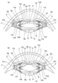
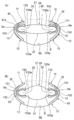
- the accommodation intraocular lens 1 is installed in the lens capsule S, as shown in FIG. 5A, the accommodation intraocular lens 1 is inserted into the lens capsule from a portion where the anterior capsule Sf is incised in a cataract surgery or the like. Inserted into S, the front support portion 11 is in contact with the inner surface of the anterior capsule Sf, and the rear support portion 12 is in contact with the inner surface of the posterior capsule Sb, with the accommodating intraocular lens 1 parallel to the lens capsule S. Install. At this time, since the distance H between the front support part 11 and the rear support part 12 is longer than the distance between the front capsule Sf and the rear capsule Sb, the front support part 11 and the rear support part 12 are respectively the front capsule Sf and the rear capsule Sb.
- each connecting piece 131 is bent in such a manner as to expand outward in the radial direction based on the bent portion 132, and the front support portion 11 moves the inner surface of the anterior capsule Sf by the biasing force of each connecting piece 131 generated at that time.
- the back support part 12 presses the inner surface of the posterior capsule Sb.
- ultrasonic waves before surgery are used. It is desirable to install an adjusting intraocular lens 1 (lens capsule expansion device 10) having a height that matches the thickness of the lens measured by scanning or the like.
- the front support portion 11 presses the inner surface of the anterior capsule and the rear support portion 12 presses the inner surface of the posterior capsule by the urging force of the connecting portion 13, so that the peripheral portion of the lens equator portion Se extends and expands in the front-rear direction.
- the lens equator Se expands, and at the same time, the lens equator Se moves centripetally and the diameter of the lens equator Se decreases.
- the chin zonule Z is pulled in both directions on the capsular bag S side and the ciliary body C side, and a moderately strong tension is continuously applied to the chin zonule Z.
- the capsular sac S anterior capsule Sf
- a moderately strong tension occurs in the posterior capsule Sb. Therefore, the chin band Z can accurately transmit the slight contraction and relaxation of the ciliary muscle Cm of the ciliary body C to the capsular bag S, and thus express the adjustment function of the internal optical unit 20 with high precision. It becomes possible to make it.
- the optical unit 20 when the device 10 is installed in the lens capsule S, the optical unit 20 is integrally arranged in the device 10. However, the device 10 is installed in the lens capsule S. Later, the optical unit 20 may be disposed inside the device 10.
- the device 10 when the device 10 is installed, there are a method in which the device 10 is folded and attached to an injector and inserted into the capsular bag S, or the device 10 is folded with tweezers or the like and inserted into the capsular bag S.
- the ciliary muscle Cm of the ciliary body C relaxes and becomes flat, and the ciliary body C is separated from the lens capsule S. Retracted in the direction. Then, the peripheral portion of the crystalline lens equator Se is brought outward in the radial direction by the tension of the Chin zonule Z having a moderately strong tension by the accommodation intraocular lens 1 installed in the crystalline lens capsule S. Be pulled. Thereby, since the lens capsule S is deformed so that the thickness of the lens capsule S is reduced, the distance between the front capsule Sf and the rear capsule Sb is shortened, and the front support portion 11 and the rear support portion 12 are brought closer to each other. Moving.
- each connecting piece 131 is bent in such a manner as to expand outward in the radial direction based on the bent portion 132, and the front support portion 11 of the front capsule Sf is caused by the urging force of each connecting piece 131 generated at that time.
- the rear support portion 12 presses the inner surface of the posterior capsule Sb, and the tension and balance of the chin strap Z are maintained.
- the adjustment function of the optical unit 20 can be expressed in the distance vision according to the relaxation of the ciliary muscle Cm of the ciliary body C.
- the connecting piece 131 is elastically deformed to return to a natural state, and the degree to which the connecting portion 13 is bent outward in the radial direction is reduced. Therefore, the locking members 133 move in the proximity direction to each other. The distance between the locking members 133 is shortened. Therefore, the optical part 20 is elastically deformed in such a manner that the peripheral part 22 is pressed radially inward from each connecting piece 131 of the connecting part 13 via the locking member 133 and the central part 21 swells in the thickness direction. The curvature of the central portion 21 is increased. In this way, the adjustment function of the optical unit 20 can be expressed during near vision according to the contraction of the ciliary muscle Cm of the ciliary body C.
- the accommodation intraocular lens 1 can accurately transmit the slight contraction and relaxation of the ciliary muscle Cm of the ciliary body C to the capsular bag S due to the structure of the device 10, and thus The adjustment function of the optical unit 20 can be expressed with high accuracy.
- the anterior aqueous humor passes from the anterior capsulotomy portion between the front support portion and the connecting portion, and the crystalline lens. Since it flows into the sac and the lens equator Se is exposed to the anterior aqueous humor, the proliferation or fibrosis of the lens epithelial cells in the lens equator Se is suppressed, and the occurrence of subsequent cataract can be prevented.
- the anterior aqueous humor enters from the opening 11a opened in an annular shape and surely flows into the lens equator Se from between the connecting pieces 131, so that lens epithelial cells proliferate in the lens equator Se. Or fibrosis can be suppressed reliably.
- the accommodating intraocular lens 1 directly from the connecting portion 13 according to the movement of the connecting portion 13 when moving in the approaching / separating direction of the front support portion 11 and the rear support portion 12 according to the movement of the lens capsule S. Or since force acts indirectly and the curvature of the optical part 20 changes, focus adjustment force can be exhibited with sufficient accuracy and sufficient.
- the device 10 according to the present embodiment is not provided with the locking member 133, and directly locks the peripheral portion 22 of the optical unit 20 inside each connecting piece 131.
- the front support part 11 and the rear support part 12 move away from each other, and the connecting piece 131 of the connecting part 13 is elastically deformed. Then, the state returns to a natural state, and the degree to which the connecting portion 13 is bent outward in the radial direction is reduced. Therefore, the opposing connecting pieces 131 move in the proximity direction, and the distance between the connecting pieces 131 is shortened. Therefore, the optical part 20 receives the force from each connecting piece 131 of the connecting part 13 directly at the peripheral part 22 and is pressed radially inward, and the central part 21 is elastically deformed in such a manner that the central part 21 swells in the thickness direction. 21 curvature increases.
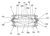
- the locking member 133 As shown in FIG. 7, the locking member 133 according to this embodiment is provided with a bulging portion 133 a on the inner side of the front end portion and the rear end portion.
- the front support part 11 and the rear support part 12 move in the proximity direction, and the connecting part 13 spreads radially outward. Since the degree increases, the connecting pieces 131 facing each other move in the separation direction, and the distance between the connecting pieces 131 becomes long. Therefore, the optical part 20 does not receive the radially inner force from each connecting piece 131 of the connecting part 13, and relaxes to the original shape, thereby reducing the curvature of the central part 21.
- the front support portion 11 and the rear support portion 12 move away from each other, and the connecting piece 131 of the connecting portion 13 is elastically deformed. Therefore, since the degree of bending of the connecting portion 13 radially outward is reduced, the opposing connecting pieces 131 move in the proximity direction to shorten the distance between the connecting pieces 131. Therefore, the optical part 20 is elastically deformed in such a manner that the peripheral part 22 is pressed radially inward from each connecting piece 131 of the connecting part 13 via the locking member 133 and the central part 21 swells in the thickness direction. The curvature of the central portion 22 is increased.
- the bulging portion 133a presses the peripheral edge portion 22 of the optical portion 20 inward to bulge the front and rear central portions 21 of the optical portion 20, so that the inclination of the optical portion 20 at the peripheral edge of the central portion 21 is increased. It becomes large and can change the curvature of the center part 21 of the optical part 20 still more effectively.
- connection part 13 which concerns on this embodiment has connected the outer peripheral part 11d of the front support part 11, and the outer peripheral part 12d of the back support part 12 integrally. According to this, since the linking band 13 and the lens capsule S can effectively have appropriate tension when the connecting portion 13 is along the lens capsule S, the movement of the ciliary muscle Cm is effectively controlled. Can be transmitted to the sac S.
- the bent portion 132 of the connecting portion 13 is formed in a U-shape or V-shape, and the bent portion 132 passes the peripheral portion 22 of the optical portion 20 in the front-rear direction. It is pinched and locked. According to this, the peripheral edge 22 of the optical part 20 can be reliably locked to the connecting part 13, and the optical part 20 can be stably arranged inside the device 1.
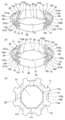
- connection part 13 which concerns on this embodiment is the 1st connection part 13a which connects the outer peripheral edge parts 11d and 12d of the front support part 11 and the back support part 12, and the inner peripheral part of the front support part 11 and the back support part 12 11c and 12c, and a second connecting portion 13b for connecting 12c.
- the first connecting portion 13a is composed of a plurality of connecting pieces 131a provided at spaced intervals in the circumferential direction of the front support portion 11 and the rear support portion 12.
- the connecting piece 131a is a thin plate-like member made of an elastic material such as synthetic resin, and one end thereof is fixed to the rear surface side of the front support portion 11 in a mode toward a right angle direction or slightly radially outward, The other end portion is fixed to the front surface side of the rear support portion 12 in a mode toward the right angle direction or slightly radially outward.
- the 1st connection part 13a is provided in the outer-periphery edge parts 11d and 12d of the front support part 11 and the back support part 12, it follows along with the lens capsule S, and a chin belt and the lens capsule S Can effectively have an appropriate tension, so that the movement of the ciliary muscle can be effectively transmitted to the capsular bag S.
- the second connecting portion 13b is provided at a balanced interval with respect to the circumferential direction of the front support portion 11 and the rear support portion 12, and a plurality of connecting pieces 131b provided between the connecting pieces 131a.
- the peripheral part 22 of the optical part 20 is pinched
- the connection piece 131b is a thin plate-like member made of an elastic material such as a synthetic resin, and one end portion is directed to the rear surface side of the front support portion 11 at a right angle or slightly radially outward. And the other end is fixed to the front surface side of the rear support portion 12 in a direction toward a right angle direction or slightly radially outward.
- the second connecting portion 13b connects the inner peripheral edge portion 11c of the front support portion 11 and the inner peripheral edge portion 12c of the rear support portion 12 as shown in FIGS.
- the second connecting portion 13b is positioned at or near the opening edge near the center of the anterior lens capsule Sf that moves most by the focus adjustment of the eyes, so the front support portion 11 and the rear support portion 12
- the degree of bending greatly changes with the movement in the front-rear direction, and the force easily acts on the optical unit 20 directly or indirectly from the second connecting portion 13b, and the curvature of the optical unit 20 changes effectively. be able to.
- the first connecting portion 13b is moved in the front-rear direction by the front support portion 11 and the rear support portion 12. Since the degree of bending of the second connecting portion 13b changes greatly, the bending of the optical portion 20 can be changed greatly.
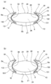
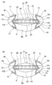
- the optical unit 20 is provided with a reinforcing member for assisting the deformation of the optical unit 20 at the peripheral portion 22.
- the reinforcing member 40 includes a plurality of U-shaped or V-shaped reinforcing members 41 that can be elastically deformed in the front-rear direction of the optical unit 20, and each reinforcing member 41 sandwiches the peripheral edge 22 of the optical unit 20. It is provided along the peripheral edge 22 at a predetermined interval.
- the degree to which the front support portion 11 and the rear support portion 12 move in the proximity direction and spread outward in the radial direction of the connecting portion 13 is increased.
- the bent portion 132 moves in the separating direction, the distance between the bent portions 132 becomes longer, and the optical portion 20 is relaxed to the original shape.
- the peripheral portion 22 closes the U-shaped reinforcing member 41 and deforms the central portion 21 with high accuracy by deforming in such a manner that the thickness decreases.
- the optical part 20 relaxes to the original shape, and the curvature of the central part 21 of the optical part 20 can be effectively reduced.
- the front support portion 11 and the rear support portion 12 move in the separating direction and the degree of spreading outward in the radial direction of the connecting portion 13 becomes small.
- the connecting piece 131 moves in the proximity direction, the distance between the two bent portions 132 is shortened, and the peripheral edge portion 22 is pressed radially inward.
- the peripheral portion 22 opens the U-shaped reinforcing member 41 and deforms the central portion 21 with high accuracy by deforming in such a manner that the thickness increases. Thereby, the curvature of the center part 21 of the optical part 20 can be enlarged effectively.
- the U-shaped reinforcing member 41 opens or closes so that the peripheral portion of the optical unit 20 Since 22 is deformed, the curvature of the optical unit 20 can be effectively changed.
- the reinforcing member 40 includes a front reinforcing ring member 42 provided on the outer surface in front of the optical unit 20, a front reinforcing ring member 42, a rear reinforcing ring member 43, and an outer surface on the rear of the optical unit.
- the front reinforcing ring member 42 and the rear reinforcing ring member 43 are connected by the U-shaped or V-shaped reinforcing member 41. According to this, since the peripheral part 22 of the optical part 20 deform
- the reinforcing member is provided on the outer surface of the elastic film 23 of the optical unit 20, but may be provided on the inner surface of the elastic film 23.
- the reinforcing member includes the front reinforcing ring member 42 and the rear reinforcing ring member 43.
- the reinforcing ring members may be provided, or neither reinforcing ring member may be provided. Also good.
- the optical unit 20 is formed of a stretchable elastic film 23 having a predetermined thickness, and the elastic film 23 is filled with a fluid substance 24.
- the peripheral portion 22 of the optical unit 20 is formed with a thickness of 20 to 100 ⁇ m
- the front and rear central portions are formed with a thickness of 5 to 20 ⁇ m
- the peripheral portion 22 is formed with the front and rear portions. It is formed to be thicker than the central portion 21.
- the peripheral portion 22 of the optical unit 20 has less local distortion, and the peripheral portion 22 is easily deformed uniformly as a whole, and accordingly, the front and rear central portions 21 of the optical unit 20.
- the central portion 21 at the front and rear of the optical unit 20 is easily formed by being thinly formed, and thus the curvature of the optical unit 20 can be effectively changed.
- the optical unit 20 may have a bulging portion 25 on the upper and lower inner surfaces of the peripheral edge portion 22. Accordingly, as shown in FIG. 11B, when the peripheral edge portion 22 is pressed inward by the connecting piece 131, the elastic film 23 is easily constricted in the vicinity of the bulging portion 25, and the curvature of the central portion 21 is made efficient. Can change well.
- the peripheral edge portion 22 is simply formed thicker than the front and rear central portions 21, but the elastic film is formed so as to gradually become thinner from the peripheral edge portion to the central portion. Also good.
- the optical unit 20 according to this modification is provided with a plurality of thick portions 22 a having a thick elastic film 23 at predetermined intervals along the peripheral edge 22 of the optical portion 20 at predetermined intervals. It has been. As a result, the peripheral portion 22 of the optical unit 20 has less local distortion, and the peripheral portion 22 tends to be uniformly deformed as a whole. Therefore, the optical quality of the optical unit 20 is improved, and the curvature of the optical unit 20 can be effectively changed.
- the optical part 20 may be mutually connected by the ring-shaped thick part 22b in which each thick part 22a was provided in the front and back.
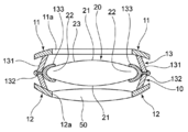
- a convex lens 50 is fitted in the opening 12a of the rear support portion 12.
- the optical part 20 can be used mainly for the purpose of obtaining adjustment power, and the convex lens 50 provided on the rear support part 12 can be used for the purpose of obtaining refractive power that matches the patient's symptoms.
- the optical part 20 can be easily folded by being formed flat, and can be inserted into the eye from a small incision in the lens capsule S.
- the convex lens 50 installed on the rear support portion 12 mainly compensates for the refractive power after the operation, the refractive error of the refractive power after the operation (the difference between the target refractive value before the operation and the actual refractive value after the operation). ) Can be reduced.
- the convex lens 50 is fitted into the opening 12 a of the rear support 12, but may be fitted into the opening 11 a of the front support 11. Moreover, although the convex lens 50 shall be fitted in the opening part 12a of the back support part 12, it is good also as what fits a concave lens.
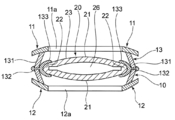
- the optical unit 20 further includes a convex lens 26 inside as shown in FIG.
- the optical unit 20 is used mainly for the purpose of obtaining adjustment power, and the convex lens 26 provided in the optical unit 20 can be used for the purpose of obtaining refractive power that matches the patient's symptoms, It is possible to reduce the refractive error of the refractive power after surgery (the difference between the target refractive value before surgery and the actual refractive value after surgery).
- the convex lens provided inside the optical unit corresponds to the embryonic nucleus portion of the human eye lens, the curvature of the optical unit can be changed more effectively.
- an injection tool 23 a for injecting a fluid substance 24 is provided in the elastic film 23.
- the fluid substance is introduced into the optical part 20 through the injection tool 23a.
- 24 can be injected, the incision for inserting the accommodating intraocular lens 1 into the capsular bag S can be made small.
- the postoperative refractive power can be easily adjusted to the target refractive power by injecting or sucking the fluid substance 24 from the injection tool.
- the injection tool 23a may be provided with a valve for preventing the fluid substance 24 from flowing backward.
- the optical unit 20 is formed such that the side surface 22c of the peripheral edge 22 is recessed in a U shape radially inward.
- the device 10 is provided with a rod-shaped locking member 133c, and the locking member 133c presses the peripheral edge of the optical unit 10 from the radial direction. It is locked with.
- the peripheral portion 22 of the optical unit 20 can be reliably locked, and the optical unit 20 is placed inside the device 1. It becomes possible to arrange stably.
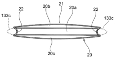
- the optical unit 10 is partitioned into three layers in the front-rear direction, and the refractive index of the partition 20 a including the center of the optical unit 20 is the refraction of the other two layers 20 b and 20 c. It is formed to be larger than the rate.
- the section 20a including the center of the optical unit 20 is filled with a fluid material that is silicon oil having a refractive index of 1.44, and the front section 20b and the rear section 20c are formed of silicon oil having a refractive index of 1.41. Is filled with a fluid substance. According to this, since the refractive index increases as it is closer to the center as in a human crystalline lens, a large change in the refractive index can be generated by slight deformation of the optical unit 20. *
- the refractive index of the fluid substance is changed by partitioning the optical unit 10, but the refractive index of the fluid substance gradually increases toward the central part by other methods. It may be formed.
Landscapes
- Health & Medical Sciences (AREA)
- Ophthalmology & Optometry (AREA)
- Cardiology (AREA)
- Oral & Maxillofacial Surgery (AREA)
- Transplantation (AREA)
- Engineering & Computer Science (AREA)
- Biomedical Technology (AREA)
- Heart & Thoracic Surgery (AREA)
- Vascular Medicine (AREA)
- Life Sciences & Earth Sciences (AREA)
- Animal Behavior & Ethology (AREA)
- General Health & Medical Sciences (AREA)
- Public Health (AREA)
- Veterinary Medicine (AREA)
- Prostheses (AREA)
Abstract
眼内レンズ1は、水晶体嚢拡張ディバイス10と、弾性変形する光学部20とからなる。水晶体嚢拡張ディバイス10は、前嚢の内面に接する態様で設けられた前方支持部11と、前方支持部11の後方側において前方支持部11と対向しながら後嚢の内面に接する態様で設けられた後方支持部12と、前方支持部11と後方支持部12を離間させる方向に付勢力を有する態様で前方支持部11と後方支持部12とを連結する連結部13とを備える。連結部13の付勢力により、前方支持部11が前嚢の内面を押圧するとともに、後方支持部12が後嚢の内面を押圧する。光学部20は、水晶体嚢の動きに応じた前方支持部11と後方支持部12との近接または離間させる連結部13の動きに連動して中央部21の曲率を変化させる。
Description
本発明は、白内障手術、屈折矯正手術あるいは老視矯正手術として行われる水晶体嚢外摘出手術のような眼科手術において、前嚢切開された水晶体嚢内に挿入される調節眼内レンズに関する。
通常、人の眼の焦点調節(以下、調節という)は、水晶体の厚みを変化させることによって行われている。図18に示すように、水晶体Lは、直径が約9~10mm、厚さが約4~5mmの凸形状をしたレンズ機能を発揮する透明なものであり、水晶体嚢Sに包まれた状態で虹彩Iの後方に位置する態様でチン小帯Zを介して毛様体Cに固定されている。
具体的な調節のメカニズムを説明すると、例えば遠方を見る場合では、図18(a)に示すように、毛様体Cの毛様体筋Cmは弛緩しており、毛様体Cが水晶体嚢Sから離間する方向に引っ込んだ位置にある。この状態であることにより、毛様体Cと水晶体赤道部Seの間に位置するチン小帯Zには比較的強い張力が生じる。このことによって、水晶体赤道部Seは径方向外側に引っ張られてその厚みが小さくなるように変形するため、これに伴って水晶体嚢S内の水晶体Lの厚みが小さくなることによって、遠方視時における焦点調整を行っている。
一方、近くの物を見るように調節努力すると、図18(b)に示すように、毛様体Cの毛様体筋Cmは収縮して毛様体Cが求心性(水晶体赤道部Se方向)に突出し、毛様体Cが水晶体嚢Sに近接する方向に位置する。これによりチン小帯Zの張力が弱まるため、水晶体Lが本来持つ弾力性によりその厚さが大きくなることによって、近方視時における焦点調整を行っている。なお、この焦点調節時において、水晶体前嚢Sfの中央に近いほどよく動き、水晶体後嚢Sbはほとんど動かないことがわかっている。
このように毛様体の毛様体筋が収縮および弛緩することに応じて水晶体の厚みを変化させ、眼に入る光を屈折させることによって焦点調節を行っている。なお、この調節のメカニズムにおいて、毛様体の毛様体筋による収縮機能および弛緩機能は、高齢になっても若い時と同様によく保たれていることがわかっているが、その一方で水晶体の内容物や水晶体嚢は高齢になると硬化して柔軟性が失われ、水晶体の厚みが変化しにくくなるため、遠方視時から近方視時にかけて随意に焦点を調節する力(以下、調節力という)が失われてしまうことがわかっている(これを老視という)。
ところで、上記水晶体に生じる病気には、主に加齢が原因となって混濁する白内障という病気があり、多くの患者がこの白内障を治療するための白内障手術を受けている。この手術は、通常、前嚢を円形切開して円形状の孔を作り、そこから超音波水晶体乳化吸引術により混濁した水晶体の内容物を摘出し、円形状の孔のある状態の透明な水晶体嚢だけを残してこの水晶体嚢内に眼内レンズを挿入するという方法が適用されている。この方法による白内障手術は、現在日本で年間100万人以上、米国で年間300万人以上の患者に対して施されており、ここに用いられる眼内レンズは単焦点レンズが一般的とされていた。
ところが、単焦点レンズは、一般的にPMMA(Poly Methyl Methacrylate)、シリコン、アクリル等の素材からなっており、単焦点レンズ自体の厚みを変化させ得るものではないため、術後にあっては調節力の喪失を避けることができなかった。これに対し、光学部に同心円状に屈折力が違う部位を設けた屈折型多焦点レンズや、光学部に光の回析現象が発生する構造を設けた回折型多焦点レンズに遠方視用や近方視用(中間視用があるものも存在する)として眼内に入る光を分散して取り入れる多焦点レンズ等が知られている。ところが、これらの多焦点眼内レンズは、光の輪が見えるハローやギラギラと輝いて見えるグレアの発生例や、視力やコントラスト感度の不良例も報告される等、患者の要求を十分に満足させるまでには至っていなかった。
また、近年では上述とは異なる方法で調節機能を発揮するものとして、凸状レンズからなる光学部と、水晶体赤道部の内側に接する態様で設けられた関節接続式の2つ連結アームとを備え、光学部が前後に移動することで調節を行う調節眼内レンズが知られている(下記特許文献1参照)。この調節眼内レンズは、連結アームがその連結アーム上の第1の位置にて光学部に取り付けられ、また連結アーム上の第2の位置にて、毛様体の毛様体筋の収縮・弛緩がチン小帯を介して伝えられる水晶体嚢の赤道部の動きと協働するというものである。
一方、白内障手術時において眼内レンズを挿入する前に水晶体嚢を拡張させるために用いられるリング状の水晶体嚢拡張ディバイスが数多く発表されている。これらのリング状水晶体嚢拡張ディバイスには目的によって2種類のものが用いられる。
1つは、Capsular Tension Ring(水晶体嚢拡張リング)と呼ばれ、C字形状に形成されたオープンリングであり、チン小帯が弱かったり断裂している水晶体赤道部に内側からこのリングを挿入して、水晶体赤道部を外側方向に拡張して形を丸く整えるというものである。
もう1つは、赤道部リングと呼ばれ、O字形状に形成されており、断面が四角形などのシャープなエッジを有するやや厚めの閉鎖型のリング(つながっているリング)である。このリングを水晶体赤道部の内側に設置して水晶体嚢に強い屈曲部を作り、水晶体上皮細胞が内側へ増殖進入することを阻止しようとするものである。
しかしながら、人の眼における焦点の調節機能は、毛様体の毛様体筋による収縮および弛緩に基づいて発現されるものであって、調節眼内レンズの光学部を前後方向に移動せしめるには、毛様体の毛様体筋の僅かな収縮・弛緩を精度良く伝達して水晶体嚢を変形させる必要がある。そのためには、毛様体の毛様体筋の収縮および弛緩を水晶体嚢に伝達するためのチン小帯が適度な強さの緊張を持続的に有し、その結果、水晶体嚢が適度な緊張を有していることが重要なのである。
これに関し、従来の調節眼内レンズは、チン小帯が適度な強さの緊張を持続的に有するように作用するものではないため、毛様体の毛様体筋による僅かな収縮および弛緩が水晶体嚢に精度良く伝達されず、光学部の前後方向への移動に精度良く転換させることが困難であり、ひいては内部に設置された眼内レンズの調節機能を精度良く発現させることができないという問題があった。
一方のリング状の水晶体嚢拡張ディバイスも同様、水晶体赤道部の位置を整えることや水晶体嚢に強い屈曲部を形成することはできるが、チン小帯に適度な強さの緊張を持続的に有させるものではなく、むしろ水晶体赤道部を外向きに拡張してチン小帯の緊張を弱める方向に働くものである。このため、毛様体の毛様体筋の僅かな収縮および弛緩が水晶体嚢に精度良く伝達されず、調節眼内レンズの調節機能を精度良く発現させることができなかった。
また、従来のリング状の水晶体嚢拡張ディバイスの多くは、連結アームやリング状の水晶体嚢拡張ディバイス自体が水晶体赤道部の内側に接しながら固定されるものであり、経時的に水晶体前嚢と後嚢が癒着して水晶体赤道部が閉鎖されることになる。近年、前房水が常に水晶体赤道部に流入している場合、後発白内障が起こりにくいということから、前房水には水晶体上皮細胞の増殖を抑制する作用があることがわかってきている。ところが、これら従来の眼内レンズ等は、水晶体赤道部が前房水に露暴されないものであることより、水晶体赤道部で水晶体上皮細胞が増殖して線維生産されることとなるため、後発白内障が発生し易い状態となっているという問題もあった。
後発白内障が発生すると、水晶体嚢中央部が混濁して光が通りにくくなるために視力が低下したり、水晶体の赤道部が前後に癒着して線維増殖がおこって硬化し、調節眼内レンズの間節接続式アームが線維で固定されて動かなくなり、調節眼内レンズの調節機能が発現されないという問題が発生する。
本発明は、上述の問題に鑑みてなされたものであり、焦点調節力を精度よくかつ十分に発揮することができるとともに、後発白内障の発生を防止することができる調節眼内レンズを提供することを目的とする。
本発明に係る調節眼内レンズは、上記目的を達成するために、白内障手術等において内容物が除去された水晶体嚢内に挿入される調節眼内レンズであって、水晶体嚢拡張ディバイスと、弾性変形する光学部とから構成され、前記水晶体嚢拡張ディバイスは、前嚢の内面に接する態様で設けられ、後方側に光を通過させる前方支持部と、前記前方支持部の後方側において該前方支持部と対向しながら後嚢の内面に接する態様で設けられ、前方側からの光を後方側に通過させる後方支持部と、前記前方支持部と前記後方支持部を離間させる方向に付勢力を有する態様で前記前方支持部と前記後方支持部とを連結する連結部とを備え、前記連結部の付勢力により、前記前方支持部が前嚢の内面を押圧するとともに、前記後方支持部が後嚢の内面を押圧し、前記光学部は、前記水晶体嚢拡張ディバイスの前記連結部に周囲を囲まれる態様で前記連結部に直接的または間接的に係止され、水晶体嚢の動きにより前記前方支持部と前記後方支持部の近接離間方向に移動するときの前記連結部の動きに応じて、前記連結部から直接的または間接的に力が作用して光学部の曲率が変化することを特徴とする。
これによれば、連結部の付勢力により前方支持部が前嚢の内面を押圧するとともに後方支持部が後嚢の内面を押圧することよって、水晶体赤道部の周辺部分が前後方向に伸展拡張しようとして水晶体赤道部が広がると同時に、水晶体赤道部が求心性に移動して、水晶体赤道部の径が縮まる。これによりチン小帯は水晶体嚢側と毛様体側の両方向に引っ張られ、チン小帯に適度な強さの緊張が持続的に付与され、その結果、水晶体嚢に適度な緊張が付与される。このため、チン小帯が毛様体の毛様体筋の僅かな収縮および弛緩を水晶体嚢に精度良く伝達することができ、ひいては内部の光学部の調節機能を精度良く発現させることが可能となる。
また、前方支持部が環状等のように開いた状態に形成されている場合、前房水が前嚢切開部から前方支持部と連結部の間を通って水晶体嚢内に流れ込み、水晶体赤道部が前房水に接し露暴されるため、水晶体赤道部における水晶体上皮細胞の増殖あるいは線維化が抑制され、後発白内障の発生を防止することができる。
さらに水晶体嚢の動きに応じて前記前方支持部と前記後方支持部の近接離間方向に移動するときの前記連結部の動きに応じて、連結部から光学部に対して直接的または間接的に力が作用して光学部の曲率が変化するため、焦点調節力を精度良くかつ十分に発揮することができる。
また、前記水晶体嚢拡張ディバイスは、前記連結部に前記前方支持部および前記後方支持部の径方向外側に広がる態様で曲がる屈曲部が形成され、前記光学部は、周縁部が前記連結部の屈曲部に直接的または間接的に係止され、水晶体嚢の動きに応じて前記前方支持部と前記後方支持部の近接離間方向に移動するときの前記連結部の動きに応じて、光学部の周縁部に前記連結部から直接的または間接的に径方向に力が作用して光学部の曲率が変化するのが好ましい。これによれば光学部の周縁部に前記連結部から直接的または間接的に径方向に力が作用して光学部の曲率が変化するため、焦点調節力をより精度良くかつ十分に発揮することができる。
また、前記水晶体嚢拡張ディバイスは、前記連結部の屈曲部の内側に係止部材が設けられ、前記光学部は、周縁部が前記連結部の屈曲部の係止部材に係止されているのが好ましい。これによれば光学部の周縁部を連結部に確実に係止することができ、光学部を水晶体嚢拡張ディバイスの内部に安定して配置することが可能となる。
また、前記係止部材は、前記光学部の径方向内側に開いたU字状またはV字状に形成され、前記光学部の周縁部を前後方向から挟んで係止するのが好ましい。これによれば光学部が弾性変形する柔らかな部材からなるものであっても、光学部の周縁部を確実に係止することができる。
また、前記係止部材は、前方端部および/または後方端部において内側に膨らむ態様の膨隆部が形成されていてもよい。これによれば光学部の周縁部を係止部材に係止させたとき、係止部材の膨隆部が光学部の周縁部を内側に押圧することにより光学部の中央部を膨出させるため、光学部の曲率がさらに効果的に変化することができる。
また、前記係止部材は、前記光学部の周縁部を径方向から押圧する態様で係止してもよい。これによれば光学部が弾性変形する比較的硬い部材からなるものであっても、光学部の周縁部を確実に係止することができる。
また、前記係止部材は、前記光学部の径方向内側に延びるロッド状に形成され、前記光学部の周縁部を径方向内側に押圧しながら係止してもよい。これによれば前記連結部から直接的または間接的に径方向に力が作用する際、光学部の曲率が変化し易くなる。
また、前記水晶体嚢拡張ディバイスは、前記連結部の屈曲部がU字状またはV字状に形成され、該屈曲部が前記光学部の周縁部を前後方向から挟んで係止してもよい。これによれば、光学部の周縁部を連結部に確実に係止することができ、光学部を水晶体嚢拡張ディバイスの内部に安定して配置することが可能となる。
また、前記水晶体嚢拡張ディバイスは、前記前方支持部および前記後方支持部の外周縁部を連結する第1の連結部と、前記前方支持部および前記後方支持部の内周縁部を連結する第2の連結部とからなり、前記光学部は、前記第2の連結部に直接的または間接的に係止されていてもよい。これによれば、第1の連結部は、前記前方支持部および前記後方支持部の外周縁部に設けられているため、水晶体嚢に沿うことによりチン小帯と水晶体嚢が効果的に適度な張力をもつことができるため、毛様体筋の動きを効果的に水晶体嚢に伝えることができる。また、第2の連結部は、前記前方支持部および前記後方支持部の内周縁部に設けられていることにより、目の焦点調節によって最も動く水晶体前嚢の中央付近にある開口縁部またはその近傍に第2の連結部が位置することになるため、前記前方支持部および前記後方支持部の前後方向の移動に伴って屈曲の度合いが大きく変化し、第2の連結部から光学部に前記連結部から直接的または間接的に力が作用し易くなり、光学部の曲率が効果的に変化することができる。また、第2の連結部は、第1の連結部より外方への屈曲が弱くなるように形成した場合、前方支持部および後方支持部の前後方向の移動に伴って、第2の連結部の屈曲の度合いが大きく変化するため、光学部の屈曲を大きく変化させることができる。
また、前記光学部は、光学部の変形を補助するための補強部材が設けられていてもよい。これによれば補助部材が光学部の変形を補助するため、光学部の曲率が効果的に変化することができる。
また、前記補強部材は、光学部の前後方向に弾性変形可能なU字状またはV字状の複数の補強部材からなり、各補強部材は光学部の周縁部を前後方向から挟む態様で該周縁部に沿って所定間隔で設けられていてもよい。これによれば光学部に水晶体嚢拡張ディバイスの連結部から直接的または間接的に力が作用したときに、U字状またはV字状の補強部材が開いたり閉じたりすることにより光学部の周縁部が変形するため、光学部の曲率が効果的に変化することができる。
また、前記補強部材は、前記光学部の前方の外面に設けられた前方補強リング部材と、前記光学部の後方の外面に設けられた後方補強リング部材とをさらに備え、前記前方補強リング部材と前記後方補強リング部材が前記光学部の周縁部に設けられたU字状またはV字状の複数の補強部材により連結されてもよい。これによればU字状またはV字状の補強部材が安定して開いたり閉じたりすることにより光学部の周縁部がより確実に変形するため、光学部の曲率がより効果的に変化することができる。
また、前記光学部は、所定の厚さの伸縮可能な弾性膜から形成され、該弾性膜の内部に流動性物質が充填されていてもよい。これによれば 光学部に前記連結部から直接的または間接的に力が作用したときに、光学部が変形し易くなるため、光学部の曲率が効果的に変化することができる。
また、前記光学部は、周縁部が20~100μmの厚さで形成されるとともに、中央部が5~20μmの厚さで形成され、周縁部が中央部よりも厚く形成されていてもよい。特に前記光学部は、周縁部から中央部にかけて次第に弾性膜が薄くなるように形成されていいるが好ましい。これによれば光学部の周縁部は局所的な歪みが少なくなって、周縁部が全体的に均一に変形し易くなり、それに伴って光学部の中央部も均一に変形し易くなるとともに、光学部の中央部は薄く形成されることにより変形し易くなるため、光学部の曲率が効果的に変化することができる。
また、前記光学部は、前記弾性膜が厚い部分が周縁部に沿って所定間隔で形成されていてもよい。これによれば光学部の周縁部は局所的な歪みが少なくなって、周縁部が全体的に均一に変形し易くなり、それに伴って光学部の中央部も均一に変形し易くなるため、光学部の曲率が効果的に変化することができる。
また、前記光学部は、前記弾性膜の厚い部分の前方端部および/または後方端部において内側に膨らむ態様の膨隆部が形成されていてもよい。これによれば光学部が変形するときに、膨隆部の付近において光学部の周縁部がくびれ易くなり、それに伴って光学部の中央部が膨出し易くなるため、光学部の曲率が効果的に変化することができる。
また、前記光学部は、流動性物質が中心部に向かって次第に屈折率が大きくなるように形成されていてもよい。例えば、前記光学部は、前後方向に区画され、前記光学部の中心を含む区画の屈折率が他の区画の屈折率より大きくなるように形成されてもよい。これによれば人間の水晶体のように中心部に近いほど屈折率が大きいものになるため、わずかな光学部の変形により大きな屈折率の変化を生み出すことができる。
また、前記光学部は、中心部において前記流動性物質よりも剛性を有する核部材が設けられていてもよい。これによれば、光学部が連結部から直接的または間接的に力が作用した際、核物質の周りに存在する流動性物質が効率的に弾性膜に力を及ぼすため、光学部の曲率が効率的に変化することができる。
また、前記核部材は、患者の症例に合わせた屈折力を有する凸レンズであってもよい。これによれば光学部は主に調節力を得る目的で使用し、光学部の内部に設けられた凸レンズは患者の症状に合わせた屈折力を得る目的で使用することができ、術後における屈折力の屈折誤差(術前の目標屈折値と術後の実際の屈折値との差)を軽減することが可能となる。
また、前記光学部は、内部に流動性物質を注入するための注入具が設けられていてもよい。これによれば光学部の中の流動性物質が無い又は少ない状態で光学部を折り畳んで水晶体嚢拡張ディバイスに挿入したあと、注入具を通じて光学部の内部に流動性物質を注入し得るため、調節眼内レンズを水晶体嚢に挿入するための切開創を小さくすることができる。また、手術後に屈折誤差が生じたときに、流動性物質を注入具から注入または吸引することにより術後の屈折力を目標となる屈折力となるように容易に調整することができる。
前記水晶体嚢拡張ディバイスは、前記後方支持部に患者の症例に合わせた屈折力を有する凸レンズ又は凹レンズが設けられていてもよい。これによれば弾性変形する光学部は主に調節力を得る目的で使用し、後方支持部に設けられた凸レンズまたは凹レンズは患者の症状の合わせた屈折力を得る目的で使用することができる。このため弾性変形する光学部は偏平に形成することにより容易に折り畳み易くなり、水晶体嚢の小切開創から眼内に挿入することが可能となる。また、後方支持部に設置された凸レンズまたは凹レンズは主に術後の屈折力を補うため、術後における屈折力の屈折誤差(術前の目標屈折値と術後の実際の屈折値との差)を軽減することが可能となる。
本発明によれば、連結部の付勢力により前方支持部が前嚢の内面を押圧するとともに後方支持部が後嚢の内面を押圧することよって、水晶体赤道部の周辺部分が前後方向に伸展拡張しようとして水晶体赤道部が広がると同時に、水晶体赤道部が求心性に移動して、水晶体赤道部の径が縮まる。これによりチン小帯は水晶体嚢側と毛様体側の両方向に引っ張られ、チン小帯に適度な強さの緊張が持続的に付与され、その結果、水晶体嚢に適度な緊張が付与される。このため、チン小帯が毛様体の毛様体筋の僅かな収縮および弛緩を水晶体嚢に精度良く伝達することができ、ひいては内部の光学部の調節機能を精度良く発現させることが可能となる。
また、前方支持部が環状等のように開いた状態に形成されている場合、前房水が前嚢切開部から前方支持部と連結部の間を通って水晶体嚢内に流れ込み、水晶体赤道部が前房水に接し露暴されるため、水晶体赤道部における水晶体上皮細胞の増殖あるいは線維化が抑制され、後発白内障の発生を防止することができる。
さらに水晶体嚢の動きに応じて前記前方支持部と前記後方支持部の近接離間方向に移動するときの前記連結部の動きに応じて、連結部から光学部に対して直接的または間接的に力が作用して光学部の曲率が変化するため、焦点調節力を精度良くかつ十分に発揮することができる。
<第1の実施形態>
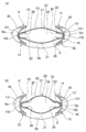
次に、本発明に係る調節眼内レンズの第1の実施形態について、図1~図5を参照しつつ説明する。
次に、本発明に係る調節眼内レンズの第1の実施形態について、図1~図5を参照しつつ説明する。
この調節眼内レンズ1は、水晶体嚢拡張ディバイス(以下、ディバイス10という)と、ディバイス10の内部に配置される光学部20とからなる。なお、図面中に示す矢印Aが指す方向を前方、その反対方向を後方として以下説明する。
[ディバイスの構成]
前記ディバイス10は、図5に示すように、白内障手術、屈折矯正手術あるいは老視矯正手術として行われる水晶体嚢外摘出手術のような眼科手術において前嚢Sfが切開された水晶体嚢S内に設置されるものである。このディバイス10は、図1に示すように、水晶体嚢S内の前方側に位置する前方支持部11と、水晶体嚢S内の後方側に位置する後方支持部12と、前方支持部11と後方支持部12を連結する連結部13とを備えている。
前記ディバイス10は、図5に示すように、白内障手術、屈折矯正手術あるいは老視矯正手術として行われる水晶体嚢外摘出手術のような眼科手術において前嚢Sfが切開された水晶体嚢S内に設置されるものである。このディバイス10は、図1に示すように、水晶体嚢S内の前方側に位置する前方支持部11と、水晶体嚢S内の後方側に位置する後方支持部12と、前方支持部11と後方支持部12を連結する連結部13とを備えている。
前記前方支持部11は、図1および図2に示すように、中央に開口部11aを有する環状に形成された弾性部材である。この前方支持部11は、図3に示すように、前面側において内周縁部から外周縁部に向かうに連れて次第に後方側に傾斜する傾斜面11bを有している。このため前方支持部11は、図5に示すように、白内障手術等において水晶体嚢Sの前嚢Sfの内面に接する態様で設けられるものであるため、前方支持部11が前嚢Sfと接した際には傾斜面11bが前嚢Sfへの接触負荷を軽減することができる。また、前方支持部11は弾性素材からなるため、前嚢Sfから受ける力に応じて多少変形し、前方支持部11と前嚢Sfにおける接触負荷をより軽減することができる。
また、前記前方支持部11は、一般的な水晶体の直径が約9~10mmで、厚さが約3.5~5.5mmであることに基づいて、外周縁部11dの直径が7.0mm、開口部11a(内周縁部11c)の直径が5.0mm、前嚢Sfと接する傾斜面11bの幅が1.5mmで、厚みが0.2~0.5mmに形成されている。
また、前方支持部11は、図2に示すように、内周縁部11cから外周縁部11dに向かって放射状の切れ込み11eが設けられている。このように切れ込み11eが設けられたことにより、前方支持部11の内周縁部11cが前後方向に大きく移動し得ることから、連結部13の屈曲部132の屈曲の度合いの変化が大きいため、光学部20の中央部21の曲率を効果的に変化させることができる。なお、前方支持部11の前面または後面に切れ込み11eの先端部同士を結ぶ態様の溝11fを形成した場合、連結部13の屈曲部132の屈曲の度合いの変化を大きくすることができる。
前記後方支持部12は、前方支持部11と同様に、中央に開口部12aを有する環状に形成された弾性部材であり、前方支持部11の後方側において前方支持部11と平行に対向する態様で配置されている。この後方支持部12は、図4に示すように、後面側において内周縁部12cから外周縁部12dに向かうに連れて次第に前方側に傾斜する傾斜面12bを有している。このため後方支持部12は、図5に示すように、水晶体嚢Sの後嚢Sbの内面に接する態様で設けられるものであるため、後方支持部12が後嚢Sbと接した際には傾斜面12bが後嚢Sbへの接触負荷を軽減することができる。また、後方支持部12は弾性素材からなるため、後嚢Sbから受ける力に応じて多少変形し、後方支持部12と後嚢Sbにおける接触負荷をより軽減することができる。また、後方支持部12の厚みは、内周縁部から外周縁部に向かって次第に薄くなる態様で形成されるのが好ましい。
また、この後方支持部12は、一般的な水晶体の大きさに基づいて、図4に示すように、外周縁部12dの直径が7.0mm、開口部12a(内周縁部12c)の直径が5.0mm、後嚢Sbとの接する傾斜面12bの幅が1.5mm、厚みが内周縁部から外周縁部に向かって0.6mm~0.2mmで形成されている。このように、後方支持部12が前方支持部11より幅を大きく設定することにより、前方支持部11が前嚢Sfと接触するよりも後方支持部12が後嚢Sbと広く接触するため、水晶体嚢S内において後方支持部12を安定して配置することができる。
前記連結部13は、図1に示すように、前方支持部11および後方支持部12の周方向について互いに均衡な間隔を空けて設けられた8個の連結片131からなる。この連結片131は、合成樹脂等の弾性素材からなる薄い板状部材であり、一方端部が前方支持部11の後面側に直交方向またはやや径方向外側に向かう態様で固定されているとともに、他方端部が後方支持部12の前面側に直交方向またはやや径方向外側に向かう態様で固定されている。
また、前記連結部13は、連結片131が弾性変形していない自然な状態では、前方支持部11と後方支持部12を所定間隔Hで連結する。この所定間隔Hは、本ディバイス1が水晶体嚢S内に設置されたときに連結片131が僅かに曲がることができる程度の長さである。また、この連結部13は、前方支持部11および後方支持部12が互いに近接する方向に移動した場合、前方支持部11および後方支持部12の径方向外側に広がる態様で曲がる。このため、ディバイス10が水晶体嚢S内に設置された際には、連結片131が径方向外側に曲がった状態となり、そのときに生じる元に戻ろうとする弾性力を利用して、前方支持部11と後方支持部12を離間させる方向に連結部13が付勢力を有する状態にすることができる。また、この連結部13は、複数の連結片131の付勢力により、全周に亘って効率的に前嚢Sfと後嚢Sbを前後方向に伸展拡張して水晶体赤道部Seを開き、チン小帯Zおよび水晶体嚢Sに適度な強さの緊張を与えることができる。
また、前記連結部13は、毛様体Cの毛様体筋Cmの収縮時または弛緩時に生じるチン小帯Zおよび水晶体嚢Sの張力に対応した付勢力を有するように長さと付勢力が調節されている。これにより、ディバイス10が水晶体嚢S内に設置された際にチン小帯Zおよび水晶体嚢Sに対してより適度な強さの緊張を持続的に付与することができる。
また、前記連結部13は、図3に示すように、前方支持部11の内周縁部11cと後方支持部12の内周縁部12cとを連結している。これにより、眼の焦点調節によって最もよく動く水晶体前嚢Sfの中央付近にある開口縁部またはその近傍に連結部13が位置するため、焦点調節により毛様体筋の収縮および弛緩による水晶体前嚢Sfの動きに応じて連結部13の屈曲の変化の度合を大きくすることができ、連結部13の屈曲に応じて変化する光学部20の中央部21の曲率を効果的に変化させることができる。
また、前記連結部13は、図4に示すように、前方支持部11および後方支持部12の径方向外側に広がる態様で連結片131が曲がるための屈曲部132が予め形成されている。このため、後述するように前方支持部11と後方支持部12が近接方向に移動した場合、この屈曲部132に基づいて連結部13が径方向外側に広がる態様で確実に曲がることができる。しかも、この屈曲部132は折曲する態様で曲がるものとなされているため、この折曲している屈曲部132に基づいて連結部13が径方向外側に広がる態様でより確実に曲がることができる。
また、前記連結部13は、図4に示すように、各屈曲部132の内側に係止部材133を備える。この係止部材133は、光学部20の径方向内側に開いた態様のU字状またはV字状に形成され、光学部20の周縁部22を前後方向から挟むことにより、U字状またはV字状の谷部分に光学部20の周縁部22を抱えて係止している。これによれば、光学部20が弾性変形する柔らかな部材からなるものであっても、光学部20の周縁部22を確実に係止することができる。なお、係止部133が光学部20の周縁部22を係止するに際して、係止部材133と光学部20の周縁部22の間に隙間が空くようにしてよい。
これら各係止部材133は、前方支持部11と後方支持部12が近接方向に移動することにより連結部13の径方向外側に広がる度合いが大きくなると、径方向において互いに離間する方向に移動して、対向する係止部材133間の距離が長くなる。また、各係止部材133は、前方支持部11と後方支持部12が離間方向に移動することにより連結部13の径方向外側に広がる度合いが小さくなると、径方向において互いに近接する方向に移動して、対向する係止部材133間の距離が短くなる。
[光学部の構成]
前記光学部20は、5~100μmの厚さの弾性膜から形成された偏平状の凸レンズであって、内部に流動性物質24が充填されている。この光学部20は、光学部20の中央に位置し光を屈折する中央部21と、光学部20の周縁に位置する周縁部22とを備える。
前記光学部20は、5~100μmの厚さの弾性膜から形成された偏平状の凸レンズであって、内部に流動性物質24が充填されている。この光学部20は、光学部20の中央に位置し光を屈折する中央部21と、光学部20の周縁に位置する周縁部22とを備える。
なお、光学部20は、シリコンポリマー、アクリルポリマー、温度応答性の形状記憶疎水性アクリル、Hydroxyethyl Methacrylate、光硬化性樹脂、またはハイドロゲルなど若年者の水晶体と同程度の弾性を有する素材で構成されている。これによれば、光学部20に連結部13から直接的または間接的に力が作用したときに、光学部20が弾性変形し易くなるため、光学部20の曲率が効果的に変化することができる。
前記中央部21は、光学部20の中央に位置し、光を屈折し焦点調節する機能を有する部分である。この中央部21は、遠方を見る場合(非調節時)、光学部の周縁部22が連結部13の各連結片131により径方向内側に押圧されていないため、光学部20が本来有する形状まで弛緩することにより曲率が小さくなる。また、中央部21は、近方を見る場合(焦点調節時)、光学部20の周縁部22が連結部13の各連結片131により径方向内側に押圧されると、光学部20の厚さ方向に膨らむ態様で弾性変形することにより曲率が大きくなる。
また、前記周縁部22は、光学部20の周縁に位置し、ディバイス10の内部に設けられたU字状またはV字状の係止部材133に係止されている。これによれば、周縁部22は係止部材133を介して連結部13に確実に係止されるため、光学部20をディバイス1の内部に安定して配置することができる。また、光学部20の周縁部22に連結部13から径方向に力が作用し易くなり、光学部20の曲率が効果的に変形することができる。
[調節眼内レンズの設置]
次に、調節眼内レンズ1の設置について図5を参照しつつ説明する。
次に、調節眼内レンズ1の設置について図5を参照しつつ説明する。
まず、ディバイス10の内部に光学部20を収容するに際しては、ディバイス10の前方支持部11または後方支持部12の開口部11a、12aから光学部20を挿入したあと、光学部20の周縁部22を連結部13の各連結片131の係止部材133に係止させる。これにより光学部20は、前方支持部11および後方支持部12の間において、光学部20が連結部13の各連結片131に囲まれるようにして、前方支持部11および後方支持部12と平行となる態様で収容される。
次に、調節眼内レンズ1を水晶体嚢S内に設置するに際しては、図5(a)に示すように、白内障手術等において前嚢Sfが切開された部分から調節眼内レンズ1を水晶体嚢S内に挿入し、前方支持部11が前嚢Sfの内面に接するとともに、後方支持部12が後嚢Sbの内面に接する態様で、調節眼内レンズ1を水晶体嚢S内に平行な状態で設置する。このとき、前方支持部11と後方支持部12間の距離Hが前嚢Sfと後嚢Sb間の距離よりも長いため、前方支持部11と後方支持部12がそれぞれ前嚢Sfと後嚢Sbに抑えつけられながら近接方向に移動する。このため各連結片131が屈曲部132に基づいて径方向外側に向かって広がる態様で曲がった状態となり、そのときに生じる各連結片131の付勢力により前方支持部11が前嚢Sfの内面を押圧するとともに、後方支持部12が後嚢Sbの内面を押圧する。なお、水晶体嚢S(前嚢Sfおよび後嚢Sb)に毛様体Cの毛様体筋Cmの収縮および弛緩に相当する適度な強さの緊張を付与するためには、術前の超音波スキャン等で測定した水晶体の厚みに合わせた高さをもった調節眼内レンズ1(水晶体嚢拡張ディバイス10)を設置することが望ましい。
したがって、連結部13の付勢力により前方支持部11が前嚢の内面を押圧するとともに後方支持部12が後嚢の内面を押圧することよって、水晶体赤道部Seの周辺部分が前後方向に伸展拡張しようとして水晶体赤道部Seが広がると同時に、水晶体赤道部Seが求心性に移動して、水晶体赤道部Seの径が縮まる。これによりチン小帯Zは水晶体嚢S側と毛様体C側の両方向に引っ張られ、チン小帯Zに適度な強さの緊張が持続的に付与された結果、水晶体嚢S(前嚢Sfおよび後嚢Sb)に適度な強さの緊張が生ずる。このため、チン小帯Zが毛様体Cの毛様体筋Cmの僅かな収縮および弛緩を水晶体嚢Sに精度良く伝達することができ、ひいては内部の光学部20の調節機能を精度良く発現させることが可能となる。
なお、本実施形態では、水晶体嚢Sの内部にディバイス10を設置する際、ディバイス10内に光学部20を一体的に配置する場合について説明したが、水晶体嚢Sの内部にディバイス10を設置した後に、ディバイス10の内部に光学部20を配置してもよい。なお、ディバイス10の設置に際しては、ディバイス10をインジェクターに折り畳んで装着して水晶体嚢Sの内部に挿入したり、ディバイス10をピンセット等で折り畳んで水晶体嚢Sの内部に挿入する方法が挙げられる。
[調節眼内レンズの焦点調節の機能]
次に、水晶体嚢S内に設置された調節眼内レンズ1による焦点調節の機能について説明する。
次に、水晶体嚢S内に設置された調節眼内レンズ1による焦点調節の機能について説明する。
図5(a)に示すように、遠方を見る場合(非調節時)、毛様体Cの毛様体筋Cmは弛緩して扁平状になり、毛様体Cが水晶体嚢Sから離間する方向に引っ込んでいる。そして、水晶体嚢S内に設置された調節眼内レンズ1によって適度な強さの緊張を持続的に有しているチン小帯Zの張力により、水晶体赤道部Seの周辺部分が径方向外側に引っ張られる。これにより、水晶体嚢Sの厚みが小さくなるように水晶体嚢Sが変形するため、前嚢Sfと後嚢Sbの間の距離が短くなり、前方支持部11と後方支持部12が互いに近接方向に移動する。このことより、各連結片131が屈曲部132に基づいて径方向外側に向かって広がる態様で曲がった状態となり、そのときに生じる各連結片131の付勢力により前方支持部11が前嚢Sfの内面を押圧するとともに、後方支持部12が後嚢Sbの内面を押圧して、チン小帯Zの張力と均衡を保った状態となる。
このとき連結部13が径方向外側に広がる度合いが大きくなるため、各連結片131の係止部材133が互いに離間方向に移動して、対向する係止部材133間の距離が長くなる。よって、光学部20は、連結部13の各連結片131から径方向内側の力を受けなくなり、本来有する形状まで弛緩することにより中央部21の曲率が小さくなる。このように、毛様体Cの毛様体筋Cmの弛緩に応じて遠方視時について光学部20の調節機能を発現させることができる。
一方、近くの物を見る場合(焦点調節時)、図5(b)に示すように、毛様体Cの毛様体筋Cmは収縮して求心性(水晶体嚢S側)に突出し、チン小帯Zの緊張の度合いが弛む。それによって、水晶体赤道部Seの周辺部分における緊張が緩むため、連結部13による付勢力により前方支持部11および後方支持部12が付勢され、チン小帯Zの張力に抗しながら離間方向に移動していく。
このとき連結片131が弾性変形して自然な状態に戻っていき、連結部13が径方向外側に曲がる度合いが小さくなるため、各係止部材133が互いに近接方向に移動して、対向する両係止部材133間の距離が短くなる。よって、光学部20は、周縁部22が連結部13の各連結片131から係止部材133を介して径方向内側に押圧され、中央部21が厚さ方向に膨らむ態様で弾性変形することにより中央部21の曲率が大きくなる。このように、毛様体Cの毛様体筋Cmの収縮に応じて近方視時について光学部20の調節機能を発現させることができる。
これにより、調節眼内レンズ1は、ディバイス10の構造によりチン小帯Zが毛様体Cの毛様体筋Cmの僅かな収縮および弛緩を水晶体嚢Sに精度良く伝達することができ、ひいては光学部20の調節機能を精度良く発現させることが可能となる。
また、調節眼内レンズ1は、前方支持部11が環状等のように開いた状態に形成されている場合、前房水が前嚢切開部から前方支持部と連結部の間を通って水晶体嚢内に流れ込み、水晶体赤道部Seが前房水に露暴されるため、水晶体赤道部Seにおける水晶体上皮細胞の増殖あるいは線維化が抑制され、後発白内障の発生を防止することができる。特に本実施形態では、前房水は環状に開かれた開口部11aから入って、各連結片131の間から水晶体赤道部Seに確実に流入するため、水晶体赤道部Seにおける水晶体上皮細胞の増殖あるいは線維化を確実に抑制することができる。
さらに、調節眼内レンズ1は、水晶体嚢Sの動きに応じて前方支持部11と後方支持部12の近接離間方向に移動するときの連結部13の動きに応じて、連結部13から直接的または間接的に力が作用して光学部20の曲率が変化するため、焦点調節力を精度良くかつ十分に発揮することができる。
<第2の実施形態>
次に、本発明に係る調節眼内レンズ1の第2の実施形態について図6を参照しつつ説明する。なお、以下では上記の実施形態と異なる構成についてのみ説明することとし、同一の構成については説明を省略して同一の符号を付すこととする。
次に、本発明に係る調節眼内レンズ1の第2の実施形態について図6を参照しつつ説明する。なお、以下では上記の実施形態と異なる構成についてのみ説明することとし、同一の構成については説明を省略して同一の符号を付すこととする。
本実施形態に係るディバイス10は、図6に示すように、係止部材133が設けられておらず、各連結片131の内側に光学部20の周縁部22を直接係止している。
而して、図6(a)に示すように、遠方を見る場合(焦点非調節時)、前方支持部11と後方支持部12が互いに近接方向に移動し、連結部13が径方向外側に広がる度合いが大きくなるため、対向する連結片131が互いに離間方向に移動して、各連結片131間の距離が長くなる。よって、光学部20は、連結部13の各連結片131から径方向内側の力を受けなくなり、本来有する形状まで弛緩することにより中央部21の曲率が小さくなる。
また、図6(b)に示すように、近方を見る場合(焦点調節時)、前方支持部11と後方支持部12が互いに離間方向に移動し、連結部13の連結片131が弾性変形して自然な状態に戻っていき、連結部13が径方向外側に曲がる度合いが小さくなるため、対向する連結片131が互いに近接方向に移動して各連結片131間の距離が短くなる。よって、光学部20は、周縁部22が連結部13の各連結片131から力を直接受けて径方向内側に押圧され、中央部21が厚さ方向に膨らむ態様で弾性変形することにより中央部21の曲率が大きくなる。
<第3の実施形態>
次に、本発明に係る調節眼内レンズ1の第3の実施形態について図7を参照しつつ説明する。
次に、本発明に係る調節眼内レンズ1の第3の実施形態について図7を参照しつつ説明する。
本実施形態に係る係止部材133は、図7に示すように、前方端部および後方端部の内側に膨隆部133aが設けられている。
而して、図7(a)に示すように遠方を見る場合(焦点非調節時)、前方支持部11と後方支持部12が互いに近接方向に移動し、連結部13が径方向外側に広がる度合いが大きくなるため、対向する連結片131が互いに離間方向に移動して、各連結片131間の距離が長くなる。よって、光学部20は、連結部13の各連結片131から径方向内側の力を受けなくなり、本来有する形状まで弛緩することにより中央部21の曲率が小さくなる。
また、図7(b)に示すように近方を見る場合(焦点調節時)、前方支持部11と後方支持部12が互いに離間方向に移動し、連結部13の連結片131が弾性変形して自然な状態に戻っていき、連結部13が径方向外側に曲がる度合いが小さくなるため、対向する連結片131が互いに近接方向に移動して各連結片131間の距離が短くなる。よって、光学部20は、周縁部22が連結部13の各連結片131から係止部材133を介して径方向内側に押圧され、中央部21が厚さ方向に膨らむ態様で弾性変形することにより中央部22の曲率が大きくなる。このとき膨隆部133aが光学部20の周縁部22を内側に押圧することにより光学部20の前方および後方の中央部21を膨出させるため、中央部21の周縁での光学部20の傾きが大きくなって、光学部20の中央部21の曲率をさらに効果的に変化させることができる。
なお、本実施形態に係る連結部13は、前方支持部11の外周縁部11dと後方支持部12の外周縁部12dとを一体的に連結している。これによれば、連結部13は水晶体嚢Sに沿うことによりチン小帯Zと水晶体嚢Sが効果的に適度な張力をもつことができるため、毛様体筋Cmの動きを効果的に水晶体嚢Sに伝えることができる。
<第4の実施形態>
次に、本発明に係る調節眼内レンズ1の第4の実施形態について図8を参照しつつ説明する。
次に、本発明に係る調節眼内レンズ1の第4の実施形態について図8を参照しつつ説明する。
本実施形態に係るディバイス10は、図8に示すように、連結部13の屈曲部132がU字状またはV字状に形成され、該屈曲部132が光学部20の周縁部22を前後方向から挟んで係止している。これによれば、光学部20の周縁部22を連結部13に確実に係止することができ、光学部20をディバイス1の内部に安定して配置することが可能となる。
<第5の実施形態>
次に、本発明に係る調節眼内レンズ1の第5の実施形態について図9を参照しつつ説明する。
次に、本発明に係る調節眼内レンズ1の第5の実施形態について図9を参照しつつ説明する。
本実施形態に係る連結部13は、前方支持部11および後方支持部12の外周縁部11d、12dを連結する第1の連結部13aと、前方支持部11および後方支持部12の内周縁部11c、12cを連結する第2の連結部13bとからなる。
前記第1の連結部13aは、前方支持部11および後方支持部12の周方向について互いに均衡な間隔を空けて設けられた複数の連結片131aからなる。この連結片131aは、合成樹脂等の弾性素材からなる薄い板状部材であり、一方端部が前方支持部11の後面側に直角方向またはやや径方向外側に向かう態様で固定されているとともに、他方端部が後方支持部12の前面側に直角方向またはやや径方向外側に向かう態様で固定されている。
これによれば、第1の連結部13aが、前方支持部11および後方支持部12の外周縁部11d、12dに設けられているため、水晶体嚢Sに沿うことによりチン小帯と水晶体嚢Sが効果的に適度な張力をもつことができるため、毛様体筋の動きを効果的に水晶体嚢Sに伝えることができる。
一方、前記第2の連結部13bは、前方支持部11および後方支持部12の周方向について互いに均衡な間隔を空けて設けられ、それぞれが連結片131aの間に設けられた複数の連結片131bからなり、屈曲部132bの係止部材133bを介して光学部20の周縁部22を前後方向から挟んで係止している。この連結片131bも、連結片131aと同様に、合成樹脂等の弾性素材からなる薄い板状部材であり、一方端部が前方支持部11の後面側に直角方向またはやや径方向外側に向かう態様で固定されているとともに、他方端部が後方支持部12の前面側に直角方向またはやや径方向外側に向かう態様で固定されている。
また、前記第2の連結部13bは、図9(a)(b)に示すように、前方支持部11の内周縁部11cと後方支持部12の内周縁部12cとを連結している。これにより、目の焦点調節によって最も動く水晶体前嚢Sfの中央付近にある開口縁部またはその近傍に第2の連結部13bが位置することになるため、前方支持部11および後方支持部12の前後方向の移動に伴って屈曲の度合いが大きく変化し、第2の連結部13bから光学部20に直接的または間接的に力が作用し易くなり、光学部20の曲率が効果的に変化することができる。しかも、第2の連結部13bは、第1の連結部13aより外方への屈曲が弱くなるように形成した場合、前方支持部11および後方支持部12の前後方向の移動に伴って、第2の連結部13bの屈曲の度合いが大きく変化するため、光学部20の屈曲を大きく変化させることができる。
<第6の実施形態>
次に、本発明に係る調節眼内レンズ1の第8の実施形態について図10を参照しつつ説明する。
次に、本発明に係る調節眼内レンズ1の第8の実施形態について図10を参照しつつ説明する。
本実施形態に係る光学部20は、周縁部22に光学部20の変形を補助するための補強部材が設けられている。この補強部材40は、光学部20の前後方向に弾性変形可能なU字状またはV字状の複数の補強部材41からなり、各補強部材41は光学部20の周縁部22を挟む態様で該周縁部22に沿って所定間隔で設けられている。
而して、図12(a)に示すように遠方を見る場合(焦点非調節時)、前方支持部11と後方支持部12が近接方向に移動し連結部13の径方向外側に広がる度合いが大きくなると、屈曲部132が離間方向に移動して両屈曲部132間の距離が長くなり、光学部20を本来有する形状に弛緩させる。このとき、周縁部22は、U字状の補強部材41を閉じ、厚みが減少する態様で変形することで中央部21を精度良く変形させる。これにより、光学部20が本来の形状に弛緩し、光学部20の中央部21の曲率を効果的に小さくすることができる。
また、図12(b)に示すように近方を見る場合(焦点調節時)、前方支持部11と後方支持部12が離間方向に移動し連結部13の径方向外側に広がる度合いが小さくなると、連結片131が近接方向に移動して両屈曲部132間の距離が短くなり、周縁部22が径方向内側に押圧される。このとき、周縁部22は、U字状の補強部材41を開き、厚みが増大する態様で変形することで中央部21を精度良く変形させる。これにより、光学部20の中央部21の曲率を効果的に大きくすることができる。
これによれば、光学部20にディバイス1の連結部13から直接的または間接的に力が作用したときに、U字状の補強部材41が開いたり閉じたりすることにより光学部20の周縁部22が変形するため、光学部20の曲率が効果的に変化することができる。
また、前記補強部材40は、図10に示すように、光学部20の前方の外面に設けられた前方補強リング部材42と、前方補強リング部材42と後方補強リング部材43光学部の後方の外面に設けられた後方補強リング部材43とをさらに備え、前方補強リング部材42と後方補強リング部材43が前記U字状またはV字状の補強部材41により連結されている。これによれば、U字状またはV字状の補強部材41が安定して開いたり閉じたりすることにより光学部20の周縁部22がより確実に変形するため、光学部20の曲率がより効果的に変化することができる。
なお、本実施形態では、補強部材は光学部20の弾性膜23の外面に設けるものとしたが、弾性膜23の内面に設けてもよい。
また、補強部材は前方補強リング部材42と後方補強リング部材43を備えるものとしたが、いずれか一方の補強リング部材のみを設けるものとしてもよいし、あるいはいずれの補強リング部材も設けないものとしてもよい。
<第7の実施形態>
次に、本発明に係る調節眼内レンズ1の第9の実施形態について図11を参照しつつ説明する。
次に、本発明に係る調節眼内レンズ1の第9の実施形態について図11を参照しつつ説明する。
本実施形態に係る光学部20は、図11(a)に示すように、所定の厚さの伸縮可能な弾性膜23から形成され、該弾性膜23の内部に流動性物質24が充填されている。特に本実施形態では、光学部20の周縁部22が20~100μmの厚さで形成されるとともに、前方および後方の中央部が5~20μmの厚さで形成され、周縁部22が前方および後方の中央部21よりも厚く形成されている。これによれば、光学部20の周縁部22は局所的な歪みが少なくなって、周縁部22が全体的に均一に変形し易くなり、それに伴って光学部20の前方および後方の中央部21も均一に変形し易くなるとともに、光学部20の前方および後方の中央部21は薄く形成されることにより変形し易くなるため、光学部20の曲率が効果的に変化することができる。
また、光学部20は、図11(a)に示すように、周縁部22の上側および下側の内面に膨隆部25を有していてもよい。これにより、図11(b)に示すように、連結片131により周縁部22が内側方向に押圧されたとき、膨隆部25の近傍で弾性膜23がくびれやすくなり、中央部21の曲率を効率よく変化させることができる。
なお、本実施形態では、単に周縁部22が前方および後方の中央部21よりも厚く形成されるものとしたが、周縁部から中央部にかけて次第に弾性膜が薄くなるように形成されるようにしてもよい。
<第7の実施形態の変形例>
本変形例に係る光学部20は、図12に示すように、周縁部22に所定間隔で弾性膜23が厚い複数の肉厚部22aが光学部20の周縁部22に沿って所定間隔で設けられている。これにより、光学部20の周縁部22は局所的な歪みが少なくなって、周縁部22が全体的に均一に変形しやすくなり、それに伴って光学部20の前方および後方の中央部21も均一に変形し易くなるため、光学部20の光学的な質が向上し、光学部20の曲率を効果的に変化させることができる。
本変形例に係る光学部20は、図12に示すように、周縁部22に所定間隔で弾性膜23が厚い複数の肉厚部22aが光学部20の周縁部22に沿って所定間隔で設けられている。これにより、光学部20の周縁部22は局所的な歪みが少なくなって、周縁部22が全体的に均一に変形しやすくなり、それに伴って光学部20の前方および後方の中央部21も均一に変形し易くなるため、光学部20の光学的な質が向上し、光学部20の曲率を効果的に変化させることができる。
なお、光学部20は、図12に示すように、各肉厚部22aが前後に設けられたリング状の肉厚部22bにより互いに連結されてもよい。
<第8の実施形態>
次に、本発明に係る調節眼内レンズ1の第8の実施形態について図13を参照しつつ説明する。
次に、本発明に係る調節眼内レンズ1の第8の実施形態について図13を参照しつつ説明する。
本実施形態に係る調節眼内レンズ1は、後方支持部12の開口部12aに凸レンズ50が嵌め込まれている。これによれば、光学部20は主に調節力を得る目的で使用し、後方支持部12に設けられた凸レンズ50は患者の症状の合わせた屈折力を得る目的で使用することができる。このため光学部20は偏平に形成することにより容易に折り畳み易くなり、水晶体嚢Sの小切開創から眼内に挿入することが可能となる。また、後方支持部12に設置された凸レンズ50は主に術後の屈折力を補うため、術後における屈折力の屈折誤差(術前の目標屈折値と術後の実際の屈折値との差)を軽減することが可能となる。
なお、本実施形態では、凸レンズ50は、後方支持部12の開口部12aに嵌め込まれるものとしたが、前方支持部11の開口部11aに嵌め込まれてもよい。
また、後方支持部12の開口部12aに凸レンズ50を嵌め込むものとしたが、凹レンズを嵌め込むものとしてもよい。
また、後方支持部12の開口部12aに凸レンズ50を嵌め込むものとしたが、凹レンズを嵌め込むものとしてもよい。
<第9の実施形態>
次に、本発明に係る調節眼内レンズ1の第9の実施形態について図14を参照しつつ説明する。
次に、本発明に係る調節眼内レンズ1の第9の実施形態について図14を参照しつつ説明する。
本実施形態に係る光学部20は、図14に示すように、内部にさらに凸レンズ26を備えている。これによれば、光学部20は主に調節力を得る目的で使用し、光学部20の内部に設けられた凸レンズ26は患者の症状の合わせた屈折力を得る目的で使用することができ、術後における屈折力の屈折誤差(術前の目標屈折値と術後の実際の屈折値との差)を軽減することが可能となる。また、光学部の内部に設けた凸レンズは人眼水晶体の胎生核の部分に相当するため、より効果的に光学部の曲率を変化させることができる。
<第10の実施形態>
次に、本発明に係る調節眼内レンズ1の第10の実施形態について図15を参照しつつ説明する。
次に、本発明に係る調節眼内レンズ1の第10の実施形態について図15を参照しつつ説明する。
本実施形態に係る光学部20は、図15に示すように、内部に流動性物質24を注入するための注入具23aが弾性膜23に設けられている。これによれば、光学部20の中の流動性物質24が無い又は少ない状態で光学部20を折り畳んで水晶体嚢拡張ディバイス10に挿入したあと、注入具23aを通じて光学部20の内部に流動性物質24を注入し得るため、調節眼内レンズ1を水晶体嚢Sに挿入するための切開創を小さくすることができる。また、手術後に屈折誤差が生じたときに、流動性物質24を注入具から注入または吸引することにより術後の屈折力を目標となる屈折力となるように容易に調整することができる。なお、注入具23aには、流動性物質24の逆流を防止するための弁が設けられてもよい。
<第11の実施形態>
次に、本発明に係る調節眼内レンズ1の第11の実施形態について図16を参照しつつ説明する。
次に、本発明に係る調節眼内レンズ1の第11の実施形態について図16を参照しつつ説明する。
本実施形態に係る光学部20は、図16に示すように、周縁部22の側面22cが径方向内側にU字状に陥没する態様に形成されている。
また、本実施形態に係るディバイス10は、図16に示すように、ロッド状の係止部材133cが設けられており、該係止部材133cが光学部10の周縁部を径方向から押圧する態様で係止している。
これによれば、光学部20が弾性変形する比較的硬い部材からなるものであっても、光学部20の周縁部22を確実に係止することができ、光学部20をディバイス1の内部に安定して配置することが可能となる。
<第12の実施形態>
次に、本発明に係る調節眼内レンズ1の第12の実施形態について図17を参照しつつ説明する。
次に、本発明に係る調節眼内レンズ1の第12の実施形態について図17を参照しつつ説明する。
本実施形態に係る光学部10は、図17に示すように、前後方向に3層に区画され、光学部20の中心を含む区画20aの屈折率が他の2層の区画20b、20cの屈折率より大きくなるように形成されている。例えば、光学部20の中心を含む区画20aは、屈折率1.44のシリコンオイルである流動性物質が充填され、前側の区画20bおよび後側の区画20cは、屈折率1.41のシリコンオイルである流動性物質が充填されている。これによれば人間の水晶体のように中心部に近いほど屈折率が大きいものになるため、わずかな光学部20の変形により大きな屈折率の変化を生み出すことができる。
なお、本実施形態では、光学部10を区画することにより流動性物質の屈折率を変化させるものとしたが、その他の方法により流動性物質が中心部に向かって次第に屈折率が大きくなるように形成されていてもよい。
以上、図面を参照して本発明の実施形態を説明したが、本発明は、図示した実施形態のものに限定されない。図示された実施形態に対して、本発明と同一の範囲内において、あるいは均等の範囲内において、種々の修正や変形を加えることが可能である。
Claims (22)
- 眼科手術において内容物が除去された水晶体嚢内に挿入される調節眼内レンズであって、
水晶体嚢拡張ディバイスと、弾性変形する光学部とから構成され、
前記水晶体嚢拡張ディバイスは、
前嚢の内面に接する態様で設けられ、後方側に光を通過させる前方支持部と、
前記前方支持部の後方側において該前方支持部と対向しながら後嚢の内面に接する態様で設けられ、前方側からの光を後方側に通過させる後方支持部と、
前記前方支持部と前記後方支持部を離間させる方向に付勢力を有する態様で前記前方支持部と前記後方支持部を連結する連結部とを備え、
前記連結部の付勢力により、前記前方支持部が前嚢の内面を押圧するとともに、前記後方支持部が後嚢の内面を押圧し、
前記光学部は、前記水晶体嚢拡張ディバイスの前記連結部に周囲を囲まれる態様で前記連結部に直接的または間接的に係止され、水晶体嚢の動きにより前記前方支持部と前記後方支持部の近接離間方向に移動するときの前記連結部の動きに応じて、前記連結部から直接的または間接的に力が作用して光学部の曲率が変化することを特徴とする調節眼内レンズ。 - 前記水晶体嚢拡張ディバイスは、前記連結部に前記前方支持部および前記後方支持部の径方向外側に広がる態様で曲がる屈曲部が形成され、
前記光学部は、周縁部が前記連結部の屈曲部に直接的または間接的に係止され、水晶体嚢の動きにより前記前方支持部と前記後方支持部の近接離間方向に移動するときの前記連結部の動きに応じて、光学部の周縁部に前記連結部から直接的または間接的に径方向に力が作用して光学部の曲率が変化する請求項1に記載の調節眼内レンズ。 - 前記水晶体嚢拡張ディバイスは、前記連結部の屈曲部の内側に係止部材が設けられ、
前記光学部は、周縁部が前記連結部の屈曲部の係止部材に係止されている請求項2に記載の調節眼内レンズ。 - 前記係止部材は、前記光学部の径方向内側に開いた態様のU字状またはV字状に形成され、前記光学部の周縁部を前後方向から挟んで係止する請求項3に記載の調節眼内レンズ。
- 前記係止部材は、前方端部および/または後方端部において内側に膨らむ態様の膨隆部が形成されている請求項4に記載の調節眼内レンズ。
- 前記係止部材は、前記光学部の径方向内側に延びるロッド状に形成され、前記光学部の周縁部を径方向内側に押圧しながら係止する請求項3に記載の調節眼内レンズ。
- 前記水晶体嚢拡張ディバイスは、前記連結部の屈曲部がU字状またはV字状に形成され、該屈曲部が前記光学部の周縁部を前後方向から挟んで係止する請求項2に記載の調節眼内レンズ。
- 前記水晶体嚢拡張ディバイスは、前記前方支持部および前記後方支持部の外周縁部を連結する第1の連結部と、前記前方支持部および前記後方支持部の内周縁部を連結する第2の連結部とからなり、
前記光学部は、前記第2の連結部に直接的または間接的に係止されている請求項1に記載の調節眼内レンズ。 - 前記光学部は、該光学部の変形を補助するための補強部材が設けられている請求項1に記載の調節眼内レンズ。
- 前記補強部材は、前記光学部の前後方向に弾性変形可能なU字状またはV字状の複数の補強部材からなり、前記光学部の周縁部を前後方向から挟む態様で該周縁部に沿って所定間隔で設けられている請求項9に記載の調節眼内レンズ。
- 前記補強部材は、前記光学部の前方の外面に設けられた前方補強リング部材と、前記光学部の後方の外面に設けられた後方補強リング部材とをさらに備え、前記前方補強リング部材と前記後方補強リング部材は前記光学部の周縁部に設けられたU字状またはV字状の複数の補強部材により連結されている請求項10に記載の調節眼内レンズ。
- 前記光学部は、所定の厚さの伸縮可能な弾性膜から形成され、該弾性膜の内部に流動性物質が充填されている請求項1に記載の調節眼内レンズ。
- 前記光学部は、周縁部の弾性膜が20~100μmの厚さで形成されるとともに、中央部の弾性膜が5~20μmの厚さで形成され、周縁部の弾性膜が中央部の弾性膜よりも厚く形成されている請求項12に記載の調節眼内レンズ。
- 前記光学部は、中央部から周縁部にかけて次第に弾性膜が厚くなるように形成されていいる請求項13に記載の調節眼内レンズ。
- 前記光学部は、弾性膜が厚い部分が周縁部に沿って所定間隔で形成されている請求項13または請求項14に記載の調節眼内レンズ。
- 前記光学部は、弾性膜の厚い部分の前方端部および/または後方端部において内側に膨らむ態様の膨隆部が形成されている請求項13から請求項15のいずれかに記載の調節眼内レンズ。
- 前記光学部は、前記流動性物質が中心部に向かって次第に屈折率が大きくなるように形成されている請求項12に記載の調節眼内レンズ。
- 前記光学部は、前後方向に区画され、前記光学部の中心部を含む区画の屈折率が他の区画の屈折率よりも大きくなるように形成されている請求項17に記載の調節眼内レンズ。
- 前記光学部は、中心部において前記流動性物質よりも剛性を有する核部材が設けられている請求項12に記載の調節眼内レンズ。
- 前記核部材は、患者の症例に合わせた屈折力を有する凸レンズである請求項19に記載の調節眼内レンズ。
- 前記光学部は、内部に前記流動性物質を注入するための注入具が設けられている請求項12に記載の調節眼内レンズ。
- 前記水晶体嚢拡張ディバイスは、前記後方支持部に患者の症例に合わせた屈折力を有する凸レンズ又は凹レンズが設けられている請求項1に記載の調節眼内レンズ。
Priority Applications (2)
| Application Number | Priority Date | Filing Date | Title |
|---|---|---|---|
| US15/103,610 US10028823B2 (en) | 2013-12-13 | 2014-12-10 | Accommodating intraocular lens |
| EP14870621.1A EP3081193A4 (en) | 2013-12-13 | 2014-12-10 | Adjustible intraocular lens |
Applications Claiming Priority (2)
| Application Number | Priority Date | Filing Date | Title |
|---|---|---|---|
| JP2013-257870 | 2013-12-13 | ||
| JP2013257870 | 2013-12-13 |
Publications (1)
| Publication Number | Publication Date |
|---|---|
| WO2015087930A1 true WO2015087930A1 (ja) | 2015-06-18 |
Family
ID=53371230
Family Applications (2)
| Application Number | Title | Priority Date | Filing Date |
|---|---|---|---|
| PCT/JP2014/082738 Ceased WO2015087931A1 (ja) | 2013-12-13 | 2014-12-10 | 調節眼内レンズ |
| PCT/JP2014/082735 Ceased WO2015087930A1 (ja) | 2013-12-13 | 2014-12-10 | 調節眼内レンズ |
Family Applications Before (1)
| Application Number | Title | Priority Date | Filing Date |
|---|---|---|---|
| PCT/JP2014/082738 Ceased WO2015087931A1 (ja) | 2013-12-13 | 2014-12-10 | 調節眼内レンズ |
Country Status (4)
| Country | Link |
|---|---|
| US (2) | US9968442B2 (ja) |
| EP (2) | EP3081193A4 (ja) |
| JP (2) | JP2015131104A (ja) |
| WO (2) | WO2015087931A1 (ja) |
Cited By (1)
| Publication number | Priority date | Publication date | Assignee | Title |
|---|---|---|---|---|
| US20180250124A1 (en) * | 2017-03-01 | 2018-09-06 | Ioannis Pallikaris | Devices for Reconstruction of a Lens Capsule after Cataract Surgery |
Families Citing this family (22)
| Publication number | Priority date | Publication date | Assignee | Title |
|---|---|---|---|---|
| EP2806828B1 (en) | 2012-01-24 | 2021-07-21 | The Regents of The University of Colorado, A Body Corporate | Modular intraocular lens designs and methods |
| US8900300B1 (en) | 2012-02-22 | 2014-12-02 | Omega Ophthalmics Llc | Prosthetic capsular bag and method of inserting the same |
| AU2015219461B2 (en) | 2014-02-18 | 2019-10-31 | Alcon Inc. | Modular intraocular lens designs, tools and methods |
| AU2015277207B2 (en) | 2014-06-19 | 2018-03-29 | Omega Ophthalmics Llc | Prosthetic capsular devices, systems, and methods |
| EP3250152B1 (en) | 2015-01-30 | 2025-03-12 | Alcon Inc. | Inserter for inserting a base and a lens of a modular intraocular lens into an eye |
| US9358103B1 (en) | 2015-02-10 | 2016-06-07 | Omega Ophthalmics Llc | Prosthetic capsular devices, systems, and methods |
| CN108348327B (zh) | 2015-11-04 | 2021-10-01 | 克拉维斯塔医疗有限公司 | 模块化人工晶状体设计、工具和方法 |
| JP6824576B2 (ja) * | 2015-11-25 | 2021-02-03 | 株式会社Mirai Eye | 調節眼内レンズ |
| WO2017109624A1 (en) * | 2015-12-22 | 2017-06-29 | Novartis Ag | Accommodating intraocular lens |
| US11045309B2 (en) * | 2016-05-05 | 2021-06-29 | The Regents Of The University Of Colorado | Intraocular lens designs for improved stability |
| US9993336B2 (en) | 2016-06-06 | 2018-06-12 | Omega Ophthalmics Llc | Prosthetic capsular devices, systems, and methods |
| WO2018075932A1 (en) | 2016-10-21 | 2018-04-26 | Omega Ophthalmics Llc | Prosthetic capsular devices, systems, and methods |
| US11213384B2 (en) * | 2017-03-01 | 2022-01-04 | Eye-Pcr B.V. | Devices for reconstruction of a lens capsule after cataract surgery |
| US11382736B2 (en) | 2017-06-27 | 2022-07-12 | Alcon Inc. | Injector, intraocular lens system, and related methods |
| CN108272534A (zh) * | 2018-01-23 | 2018-07-13 | 上海理工大学 | 一种可连续变焦的人工晶状体 |
| WO2019169084A1 (en) | 2018-03-01 | 2019-09-06 | Ellis Forrest J | Intraocular lens with centration lips |
| AU2019249216B2 (en) | 2018-04-06 | 2024-07-18 | Omega Ophthalmics Llc | Prosthetic capsular devices, systems, and methods |
| WO2020226711A1 (en) | 2019-05-03 | 2020-11-12 | JelliSee Ophthalmics Inc. | Intraocular lenses with shape-changing optics |
| DE102019123295B4 (de) | 2019-08-30 | 2021-04-15 | Carl Zeiss Meditec Ag | Intraokularlinse mit spezifischer, dreidimensional gekrümmter Haptik |
| JP7511218B2 (ja) * | 2019-10-17 | 2024-07-05 | 株式会社Mirai Eye | 調節眼内レンズ |
| WO2021211117A1 (en) | 2020-04-15 | 2021-10-21 | Carl Zeiss Meditec Ag | Intraocular lens and treatment apparatus |
| WO2022082170A1 (en) | 2020-10-12 | 2022-04-21 | Omega Ophthalmics Llc | Prosthetic capsular devices, systems, and methods |
Citations (9)
| Publication number | Priority date | Publication date | Assignee | Title |
|---|---|---|---|---|
| JPH1147168A (ja) | 1997-07-16 | 1999-02-23 | Henry M Israel | 眼内レンズ組立体 |
| JP2006516002A (ja) * | 2002-10-25 | 2006-06-15 | クエスト ヴィジョン テクノロジー, アイエヌシー. | 内部に屈折性液体を有するカプセル型埋込人工水晶体 |
| JP2007089810A (ja) * | 2005-09-28 | 2007-04-12 | Menicon Co Ltd | 眼内レンズ |
| US20070156236A1 (en) * | 2005-09-01 | 2007-07-05 | Stenger Donald C | Accommodating Intraocular Lens |
| US20090012609A1 (en) * | 2006-12-29 | 2009-01-08 | Advanced Medical Optics, Inc. | Multifocal accommodating intraocular lens |
| JP2010502358A (ja) * | 2007-03-08 | 2010-01-28 | キョン・ジン・パク | 眼内レンズ支持体 |
| JP2010520011A (ja) * | 2007-03-08 | 2010-06-10 | キョン・ジン・パク | 眼内レンズ組立体 |
| US20120310345A1 (en) * | 2010-02-19 | 2012-12-06 | Luis Olcina Portilla | Accomodative intraocular lens |
| US20130317607A1 (en) * | 2012-05-25 | 2013-11-28 | Charles DeBoer | Accomodating intraocular composite lens and related methods |
Family Cites Families (19)
| Publication number | Priority date | Publication date | Assignee | Title |
|---|---|---|---|---|
| US6117171A (en) * | 1998-12-23 | 2000-09-12 | Skottun; Bernt Christian | Encapsulated accommodating intraocular lens |
| US6488708B2 (en) * | 1999-04-09 | 2002-12-03 | Faezeh Sarfarazi | Open chamber, elliptical, accommodative intraocular lens system |
| US7037338B2 (en) * | 2001-12-14 | 2006-05-02 | Toshiyuki Nagamoto | Intraocular ring assembly and artificial lens kit |
| US20050021139A1 (en) * | 2003-02-03 | 2005-01-27 | Shadduck John H. | Ophthalmic devices, methods of use and methods of fabrication |
| US8048155B2 (en) * | 2002-02-02 | 2011-11-01 | Powervision, Inc. | Intraocular implant devices |
| US20040082993A1 (en) | 2002-10-25 | 2004-04-29 | Randall Woods | Capsular intraocular lens implant having a refractive liquid therein |
| US20120330415A1 (en) * | 2011-06-23 | 2012-12-27 | Anew Optics, Inc. | Haptic devices for intraocular lens |
| CA2673388C (en) * | 2006-12-22 | 2015-11-24 | Amo Groningen B.V. | Accommodating intraocular lens, lens system and frame therefor |
| US8034106B2 (en) * | 2007-02-02 | 2011-10-11 | Adoptics Ag | Interfacial refraction accommodating lens (IRAL) |
| US20110313522A1 (en) * | 2008-11-26 | 2011-12-22 | Anew Optics, Inc. | Pseudophakic Accommodating Intraocular Lens |
| AU2010203427B2 (en) * | 2009-01-09 | 2017-05-18 | Alcon Inc. | Intraocular lenses and methods of accounting for capsule size variability and post-implant changes in the eye |
| WO2010089689A1 (en) * | 2009-02-08 | 2010-08-12 | Nir Betser | Accommodative intraocular lens assembly |
| US20110071628A1 (en) * | 2009-09-24 | 2011-03-24 | Rainbow Medical Ltd. | Accommodative intraocular lens |
| US9114005B2 (en) * | 2009-11-17 | 2015-08-25 | Akkolens International B.V. | Accommodative intraocular lens driven by ciliary mass |
| US20120296424A1 (en) * | 2010-01-26 | 2012-11-22 | Nir Betser | Accomodating intraocular lens |
| US8834566B1 (en) | 2012-09-12 | 2014-09-16 | David Jones | Presbyopia-correcting intraocular lens implant |
| WO2014099759A1 (en) * | 2012-12-21 | 2014-06-26 | Novartis Ag | Intraocular lens system for monofocal vision at multiple pre-defined focal points |
| WO2014100325A1 (en) * | 2012-12-21 | 2014-06-26 | Abbott Medical Optics Inc. | Accommodating intraocular lens providing progressive power change |
| US10182905B2 (en) * | 2015-06-10 | 2019-01-22 | Richard F. Honigsbaum | Anterior-posterior-capsule-actuated hydraulic accommodative intraocular lenses and lens systems |
-
2014
- 2014-12-10 US US15/103,540 patent/US9968442B2/en active Active
- 2014-12-10 JP JP2014249710A patent/JP2015131104A/ja active Pending
- 2014-12-10 EP EP14870621.1A patent/EP3081193A4/en not_active Withdrawn
- 2014-12-10 EP EP14869790.7A patent/EP3081192A4/en not_active Withdrawn
- 2014-12-10 WO PCT/JP2014/082738 patent/WO2015087931A1/ja not_active Ceased
- 2014-12-10 WO PCT/JP2014/082735 patent/WO2015087930A1/ja not_active Ceased
- 2014-12-10 JP JP2014249829A patent/JP2015131105A/ja active Pending
- 2014-12-10 US US15/103,610 patent/US10028823B2/en active Active
Patent Citations (9)
| Publication number | Priority date | Publication date | Assignee | Title |
|---|---|---|---|---|
| JPH1147168A (ja) | 1997-07-16 | 1999-02-23 | Henry M Israel | 眼内レンズ組立体 |
| JP2006516002A (ja) * | 2002-10-25 | 2006-06-15 | クエスト ヴィジョン テクノロジー, アイエヌシー. | 内部に屈折性液体を有するカプセル型埋込人工水晶体 |
| US20070156236A1 (en) * | 2005-09-01 | 2007-07-05 | Stenger Donald C | Accommodating Intraocular Lens |
| JP2007089810A (ja) * | 2005-09-28 | 2007-04-12 | Menicon Co Ltd | 眼内レンズ |
| US20090012609A1 (en) * | 2006-12-29 | 2009-01-08 | Advanced Medical Optics, Inc. | Multifocal accommodating intraocular lens |
| JP2010502358A (ja) * | 2007-03-08 | 2010-01-28 | キョン・ジン・パク | 眼内レンズ支持体 |
| JP2010520011A (ja) * | 2007-03-08 | 2010-06-10 | キョン・ジン・パク | 眼内レンズ組立体 |
| US20120310345A1 (en) * | 2010-02-19 | 2012-12-06 | Luis Olcina Portilla | Accomodative intraocular lens |
| US20130317607A1 (en) * | 2012-05-25 | 2013-11-28 | Charles DeBoer | Accomodating intraocular composite lens and related methods |
Non-Patent Citations (1)
| Title |
|---|
| See also references of EP3081193A4 * |
Cited By (3)
| Publication number | Priority date | Publication date | Assignee | Title |
|---|---|---|---|---|
| US20180250124A1 (en) * | 2017-03-01 | 2018-09-06 | Ioannis Pallikaris | Devices for Reconstruction of a Lens Capsule after Cataract Surgery |
| US10548719B2 (en) * | 2017-03-01 | 2020-02-04 | Eye-Pcr B.V. | Devices for reconstruction of a lens capsule after cataract surgery |
| AU2018226788B2 (en) * | 2017-03-01 | 2023-11-23 | Eye-Pcr B.V. | Devices for reconstruction and tensioning of a lens capsule |
Also Published As
| Publication number | Publication date |
|---|---|
| WO2015087931A1 (ja) | 2015-06-18 |
| JP2015131104A (ja) | 2015-07-23 |
| EP3081193A1 (en) | 2016-10-19 |
| EP3081192A1 (en) | 2016-10-19 |
| US20160310263A1 (en) | 2016-10-27 |
| US10028823B2 (en) | 2018-07-24 |
| JP2015131105A (ja) | 2015-07-23 |
| EP3081193A4 (en) | 2017-08-16 |
| US9968442B2 (en) | 2018-05-15 |
| US20160310264A1 (en) | 2016-10-27 |
| EP3081192A4 (en) | 2017-08-09 |
Similar Documents
| Publication | Publication Date | Title |
|---|---|---|
| WO2015087930A1 (ja) | 調節眼内レンズ | |
| US12090044B2 (en) | Accommodating intraocular lens | |
| JP5594798B2 (ja) | 水晶体嚢拡張ディバイス | |
| US7763069B2 (en) | Accommodating intraocular lens with outer support structure | |
| US9090033B2 (en) | Presbyopia-correcting IOL using curvature change of an air chamber | |
| JP6410850B2 (ja) | 相互圧平性内面を有する再合焦可能なレンズシステム | |
| JP5481588B1 (ja) | 調節眼内レンズ | |
| TW201632151A (zh) | 雙鏡片、曲率變化調節式iol | |
| JP6824576B2 (ja) | 調節眼内レンズ | |
| EA042478B1 (ru) | Аккомодирующая интраокулярная линза |
Legal Events
| Date | Code | Title | Description |
|---|---|---|---|
| 121 | Ep: the epo has been informed by wipo that ep was designated in this application |
Ref document number: 14870621 Country of ref document: EP Kind code of ref document: A1 |
|
| WWE | Wipo information: entry into national phase |
Ref document number: 15103610 Country of ref document: US |
|
| NENP | Non-entry into the national phase |
Ref country code: DE |
|
| REEP | Request for entry into the european phase |
Ref document number: 2014870621 Country of ref document: EP |
|
| WWE | Wipo information: entry into national phase |
Ref document number: 2014870621 Country of ref document: EP |