WO2015092942A1 - Dispositif électronique - Google Patents
Dispositif électronique Download PDFInfo
- Publication number
- WO2015092942A1 WO2015092942A1 PCT/JP2013/084375 JP2013084375W WO2015092942A1 WO 2015092942 A1 WO2015092942 A1 WO 2015092942A1 JP 2013084375 W JP2013084375 W JP 2013084375W WO 2015092942 A1 WO2015092942 A1 WO 2015092942A1
- Authority
- WO
- WIPO (PCT)
- Prior art keywords
- unit
- electronic device
- connecting portion
- input
- coupled
- Prior art date
- Legal status (The legal status is an assumption and is not a legal conclusion. Google has not performed a legal analysis and makes no representation as to the accuracy of the status listed.)
- Ceased
Links
Images



Classifications
-
- G—PHYSICS
- G06—COMPUTING OR CALCULATING; COUNTING
- G06F—ELECTRIC DIGITAL DATA PROCESSING
- G06F1/00—Details not covered by groups G06F3/00 - G06F13/00 and G06F21/00
- G06F1/16—Constructional details or arrangements
- G06F1/1613—Constructional details or arrangements for portable computers
- G06F1/1633—Constructional details or arrangements of portable computers not specific to the type of enclosures covered by groups G06F1/1615 - G06F1/1626
- G06F1/1637—Details related to the display arrangement, including those related to the mounting of the display in the housing
-
- G—PHYSICS
- G06—COMPUTING OR CALCULATING; COUNTING
- G06F—ELECTRIC DIGITAL DATA PROCESSING
- G06F1/00—Details not covered by groups G06F3/00 - G06F13/00 and G06F21/00
- G06F1/16—Constructional details or arrangements
- G06F1/1613—Constructional details or arrangements for portable computers
- G06F1/1615—Constructional details or arrangements for portable computers with several enclosures having relative motions, each enclosure supporting at least one I/O or computing function
- G06F1/1616—Constructional details or arrangements for portable computers with several enclosures having relative motions, each enclosure supporting at least one I/O or computing function with folding flat displays, e.g. laptop computers or notebooks having a clamshell configuration, with body parts pivoting to an open position around an axis parallel to the plane they define in closed position
-
- G—PHYSICS
- G06—COMPUTING OR CALCULATING; COUNTING
- G06F—ELECTRIC DIGITAL DATA PROCESSING
- G06F1/00—Details not covered by groups G06F3/00 - G06F13/00 and G06F21/00
- G06F1/16—Constructional details or arrangements
- G06F1/1613—Constructional details or arrangements for portable computers
- G06F1/1633—Constructional details or arrangements of portable computers not specific to the type of enclosures covered by groups G06F1/1615 - G06F1/1626
- G06F1/1637—Details related to the display arrangement, including those related to the mounting of the display in the housing
- G06F1/1654—Details related to the display arrangement, including those related to the mounting of the display in the housing the display being detachable, e.g. for remote use
-
- G—PHYSICS
- G06—COMPUTING OR CALCULATING; COUNTING
- G06F—ELECTRIC DIGITAL DATA PROCESSING
- G06F1/00—Details not covered by groups G06F3/00 - G06F13/00 and G06F21/00
- G06F1/16—Constructional details or arrangements
- G06F1/1613—Constructional details or arrangements for portable computers
- G06F1/1633—Constructional details or arrangements of portable computers not specific to the type of enclosures covered by groups G06F1/1615 - G06F1/1626
- G06F1/1656—Details related to functional adaptations of the enclosure, e.g. to provide protection against EMI, shock, water, or to host detachable peripherals like a mouse or removable expansions units like PCMCIA cards, or to provide access to internal components for maintenance or to removable storage supports like CDs or DVDs, or to mechanically mount accessories
- G06F1/166—Details related to functional adaptations of the enclosure, e.g. to provide protection against EMI, shock, water, or to host detachable peripherals like a mouse or removable expansions units like PCMCIA cards, or to provide access to internal components for maintenance or to removable storage supports like CDs or DVDs, or to mechanically mount accessories related to integrated arrangements for adjusting the position of the main body with respect to the supporting surface, e.g. legs for adjusting the tilt angle
-
- G—PHYSICS
- G06—COMPUTING OR CALCULATING; COUNTING
- G06F—ELECTRIC DIGITAL DATA PROCESSING
- G06F1/00—Details not covered by groups G06F3/00 - G06F13/00 and G06F21/00
- G06F1/16—Constructional details or arrangements
- G06F1/1613—Constructional details or arrangements for portable computers
- G06F1/1633—Constructional details or arrangements of portable computers not specific to the type of enclosures covered by groups G06F1/1615 - G06F1/1626
- G06F1/1662—Details related to the integrated keyboard
- G06F1/1669—Detachable keyboards
-
- G—PHYSICS
- G06—COMPUTING OR CALCULATING; COUNTING
- G06F—ELECTRIC DIGITAL DATA PROCESSING
- G06F1/00—Details not covered by groups G06F3/00 - G06F13/00 and G06F21/00
- G06F1/16—Constructional details or arrangements
- G06F1/1613—Constructional details or arrangements for portable computers
- G06F1/1633—Constructional details or arrangements of portable computers not specific to the type of enclosures covered by groups G06F1/1615 - G06F1/1626
- G06F1/1675—Miscellaneous details related to the relative movement between the different enclosures or enclosure parts
- G06F1/1681—Details related solely to hinges
Definitions
- Embodiments described herein relate generally to an electronic device.
- An electronic device such as a portable computer has input devices such as a keyboard, a touch pad, and a pointing stick.
- the input device is coupled to a display device such as a liquid crystal display (LCD) for displaying images.
- LCD liquid crystal display
- One of the problems to be solved by the present invention is to provide an electronic device used in a plurality of modes.
- An electronic device includes a first part, a second part, and a hinge part.
- the first portion includes a first surface, a second surface located on the opposite side of the first surface, and a first surface located between the first surface and the second surface.
- the second portion is detachable from a third end and a connecting portion having a fourth end located on the opposite side of the third end, and the fourth end of the connecting portion.
- an input portion having a fifth end coupled.
- the hinge portion is movable between the first position where the second portion covers the display portion and the second position where the second portion covers the second surface.
- the first end of the first portion and the third end of the connecting portion are coupled.
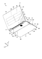
- FIG. 1 is a perspective view showing a portable computer according to one embodiment.
- FIG. 2 is a perspective view showing the portable computer of one embodiment from another direction.
- FIG. 3 is a side view of a portable computer according to one embodiment.
- FIG. 4 is a perspective view showing the portable computer of one embodiment except for a part of the first to third housings.
- FIG. 5 is a perspective view showing a display unit and a base unit according to one embodiment.
- FIG. 6 is a rear view showing the keyboard module of one embodiment.
- FIG. 7 is a side view showing a part of a tablet mode portable computer according to one embodiment.
- FIG. 8 is a side view showing a separate-mode portable computer according to one embodiment.
- FIG. 9 is a side view illustrating a tent mode portable computer according to one embodiment.
- the user side is the front
- the side far from the user is the rear
- the left side when viewed from the user is the left direction
- the right side when viewed from the user is the right direction
- the upper side when viewed from the user is upward
- the downward direction when viewed from the user is defined as the downward direction.
- a plurality of expressions may be written together for the constituent elements according to the embodiment and the description of the elements. It is not precluded that other expressions not described in the component and description are made. Furthermore, it is not prevented that other expressions are given for the components and descriptions in which a plurality of expressions are not described.
- FIG. 1 is a perspective view showing the portable computer 10.
- FIG. 2 is a perspective view showing the portable computer 10 from another direction.
- FIG. 3 is a side view of the portable computer 10.
- the portable computer 10 is an example of an electronic device.
- the electronic device is not limited to the portable computer 10 and may be various devices such as a personal computer, a television receiver, a display, a tablet, a mobile phone, a smartphone, a portable game machine, and a camera.
- the portable computer 10 includes a display unit 11, a base unit 12, and two hinge units 13.
- the display unit 11 is an example of a first portion, and may be referred to as a display unit, a module, or a unit, for example.
- the base portion 12 is an example of a second portion, and may be referred to as a main body, a module, or a unit, for example.
- the hinge part 13 can also be called a connection part, a coupling part, a rotation part, an intermediate part, or an interposition part, for example.
- an X axis, a Y axis, and a Z axis are defined.
- the X axis, the Y axis, and the Z axis are orthogonal to each other.
- the X axis is, for example, along the width (length in the longitudinal direction) of the base portion 12.
- the Y axis is, for example, along the depth (length in the short direction) of the base portion 12.
- the Z axis is, for example, along the thickness (length in the vertical direction) of the base portion 12.
- the display unit 11 includes a first housing 21 and a display module 22. As shown in FIG. 2, the display unit 11 further includes a plurality of first batteries 23.
- the first housing 21 may be referred to as an exterior part, a member, or a wall, for example.
- the display module 22 may also be referred to as a display device, a display unit, a component, or a member, for example.
- the first casing 21 is formed in a flat, substantially rectangular parallelepiped box shape.
- the first housing 21 is basically formed of, for example, a magnesium alloy. Note that the first housing 21 may be formed of other materials.
- the first housing 21 has a front surface 31, a back surface 32, a lower end portion 33, and an upper end portion 34.
- the front surface 31 is an example of a first surface.
- the back surface 32 is an example of a second surface.
- the lower end 33 is an example of a first end.
- the upper end portion 34 is an example of a second end portion.
- the lower end 33 and the upper end 34 may also be referred to as ends, edges, or parts, for example.
- the front surface 31 is formed in a substantially flat rectangular shape.
- the front surface 31 is formed of, for example, a transparent glass plate that covers a bezel (frame).
- a display opening 36 is formed in the bezel.
- the display opening 36 is a substantially rectangular hole.
- the display opening 36 is closed by the glass plate.
- the back surface 32 is located on the opposite side of the front surface 31.
- the lower end 33 includes an end surface of the first casing 21 located between the lower edge of the front surface 31 and the lower edge of the back surface 32.
- the end surface intersects the front surface 31 and the back surface 32.
- the upper end 34 is located on the opposite side of the lower end 33.
- the upper end portion 34 includes an end surface of the first housing 21 located between the upper edge of the front surface 31 and the upper edge of the back surface 32. The end surface intersects the front surface 31 and the back surface 32.
- the display module 22 is, for example, a capacitive in-cell touch panel.
- the display module 22 is not limited to this, and may be another component that displays an image, such as a liquid crystal display (LCD) or an organic electroluminescence (OEL) display to which a touch panel is attached.
- LCD liquid crystal display
- OEL organic electroluminescence
- the display module 22 is accommodated in the first casing 21.
- the display module 22 has a screen 22a.
- the screen 22a is an example of a display unit, and may be referred to as a display surface or a part.
- the screen 22a is exposed to the outside of the first casing 21 through the display opening 36 and the glass plate, and displays an image. That is, the screen 22 a of the display module 22 displays an image on the front surface 31.
- an image includes a still image, a moving image, and a monochrome screen.
- the display module 22 detects a user's finger touched by the glass plate covering the screen 22a or the display opening 36, for example.
- the display module 22 is operated by the user's finger to input information to the portable computer 10. That is, the display module 22 is not only a display device but also an input device.
- the first battery 23 is accommodated in the first housing 21.
- the first battery 23 is, for example, a lithium ion secondary battery.
- the first battery 23 may be another type of battery.
- the first battery 23 is a power source for the portable computer 10.
- the base unit 12 includes a base unit 41 and a keyboard module 42.
- the base unit 41 is an example of a connecting portion, and may be referred to as, for example, a connecting portion, a docking portion, a rotating portion, a supporting portion, a part, or a part.
- the keyboard module 42 is an example of an input unit, and may be referred to as, for example, a coupling unit, a docking unit, a detaching unit, a part, or a component.
- the base unit 41 has a second casing 51 and a power button 52.
- the second housing 51 can also be referred to as an exterior part, a member, or a wall, for example.
- the power button 52 is an example of an activation unit, and may be referred to as a button or an operation unit, for example.
- the second casing 51 is formed in a flat, substantially rectangular parallelepiped box shape.
- the second housing 51 is basically formed of, for example, a magnesium alloy. Note that the second casing 51 may be formed of other materials.
- the second housing 51 has a first upper surface 54, a first lower surface 55, a first rear end portion 56, a first front end portion 57, and two first side surfaces 58. .
- the first lower surface 55 is an example of a fifth surface.
- the first rear end portion 56 is an example of a third end portion.
- the first front end portion 57 is an example of a fourth end portion.
- the first rear end portion 56 and the first front end portion 57 may be referred to as ends, edges, or portions, for example.
- the first upper surface 54 is formed in a substantially flat rectangular shape.
- a plurality of holes 61 are provided in the first upper surface 54.
- the base unit 41 is further housed in the second housing 51 and further includes a speaker that emits sound through the plurality of holes 61.
- the first lower surface 55 is located on the opposite side of the first upper surface 54.
- a plurality of first legs 62 are provided on the first lower surface 55.
- the first legs 62 are, for example, synthetic rubber protrusions protruding from the first lower surface 55. As shown in FIG. 3, the first leg 62 is in contact with the placement surface S on which the portable computer 10 is placed and supports the base unit 41.
- the placement surface S is, for example, the upper surface of a desk.
- a plurality of air inlets 63 are provided on the first lower surface 55.
- the intake port 63 is an example of a first ventilation port, and may be referred to as a hole or an opening, for example.
- the air inlet 63 communicates with the inside of the second housing 51.
- the first rear end portion 56 includes an end surface of the second casing 51 located between the rear edge of the first upper surface 54 and the rear edge of the first lower surface 55.
- the end surface intersects the first upper surface 54 and the first lower surface 55.
- a plurality of exhaust ports 64 are provided in the first rear end portion 56.
- the exhaust port 64 is an example of a second vent hole, and may be referred to as a hole, an opening, or a slit, for example.
- the exhaust port 64 leads to the inside of the second housing 51.
- the first front end portion 57 is located on the opposite side of the first rear end portion 56.
- the first front end portion 57 includes an end surface of the second casing 51 located between the front edge of the first upper surface 54 and the front edge of the first lower surface 55. The end surface intersects the first upper surface 54 and the first lower surface 55.
- the two first side surfaces 58 are located between the right and left edges of the first upper surface 54 and the right and left edges of the first lower surface 55, respectively.
- the first side surface 58 is formed in a line-symmetric shape with respect to the center between the first upper surface 54 and the first lower surface 55 in the thickness direction (the direction along the Z axis) of the second housing 51. Is done.
- the first side surface 58 is, for example, an arcuate curved surface.
- the start button 52 is provided on one first side surface 58.
- the portable computer 10 is activated.
- the activation of the portable computer 10 is not limited to the operation of the portable computer 10 (power on), but includes, for example, recovery from the hibernation state of the portable computer 10.
- the keyboard module 42 includes a third casing 71, a keyboard 72, a pointing stick 73, a button 74, and an eject lever 75.
- the keyboard 72, the pointing stick 73, and the button 74 are examples of an operation unit, and may be referred to as, for example, an input unit, an input device, or an interface.
- the eject lever 75 is an example of a release unit, and may be referred to as a slide unit or an operation unit, for example.
- the third casing 71 is formed in a flat, substantially rectangular parallelepiped box shape.
- the third casing 71 is basically formed of, for example, a magnesium alloy. Note that the third casing 71 may be formed of other materials.
- the third casing 71 has a second upper surface 81, a second lower surface 82, a second rear end portion 83, a second front end portion 84, and two second side surfaces 85.
- the second upper surface 81 is an example of a third surface.
- the second lower surface 82 is an example of a fourth surface.
- the second rear end portion 83 is an example of a fifth end portion.
- the second front end portion 84 is an example of a sixth end portion.
- the second rear end 83 and the second front end 84 may also be referred to as ends, edges, or portions, for example.
- the second upper surface 81 is formed in a rectangular shape having a recess 81a.
- a keyboard 72, a pointing stick 73, a button 74, and an eject lever 75 are provided on the second upper surface 81.
- the keyboard 72 and the pointing stick 73 are located in the recess 81a.
- the keyboard 72, pointing stick 73, and button 74 are operated by the user to input information to the portable computer 10.
- the eject lever 75 is located between the keyboard 72 and the button 74.
- the second lower surface 82 is located on the opposite side of the second upper surface 81.
- a plurality of second legs 87 are provided on the second lower surface 82.
- the second legs 87 are, for example, synthetic rubber protrusions protruding from the second lower surface 82. As shown in FIG. 3, the second leg 87 is in contact with the placement surface S on which the portable computer 10 is placed and supports the keyboard module 42.
- the second rear end portion 83 includes an end surface of the second casing 51 located between the rear edge of the second upper surface 81 and the rear edge of the second lower surface 82.
- the end surface intersects the second upper surface 81 and the second lower surface 82.
- the second front end portion 84 is located on the opposite side of the second rear end portion 83.
- the second front end portion 84 includes an end surface of the second casing 51 located between the front edge of the second upper surface 81 and the front edge of the second lower surface 82.
- the end surface intersects the second upper surface 81 and the second lower surface 82.
- the button 74 is adjacent to the second front end 84.
- a plurality of third legs 88 are provided at the second front end portion 84.
- the third legs 88 are, for example, synthetic rubber protrusions protruding from the end surfaces of the second upper surface 81, the second lower surface 82, and the second front end portion 84. As shown in FIG. 3, the third leg 88 is in contact with the placement surface S on which the portable computer 10 is placed and supports the keyboard module 42.
- the two second side surfaces 85 are located between the right and left edges of the second upper surface 81 and the right and left edges of the second lower surface 82, respectively.
- the second side surface 85 is formed in a line-symmetric shape with respect to the center of the second upper surface 81 and the second lower surface 82 in the thickness direction (the direction along the Z axis) of the second casing 71.
- the second side surface 85 is, for example, an arcuate curved surface having the same polarity radius as that of the first side surface 58.
- FIG. 4 is a perspective view of the portable computer 10 excluding a part of the first casing 21, the second casing 51, and the third casing 71.
- the base unit 41 further includes a substrate 91, a first communication unit 92, a cooling unit 93, and a plurality of input / output components 94.
- the substrate 91 is an example of a module, and may be referred to as a component, for example.
- the substrate 91, the first communication unit 92, the cooling unit 93, and the input / output component 94 are accommodated in the second casing 51.
- the substrate 91, the first communication unit 92, the cooling unit 93, and the input / output component 94 may be accommodated in the first casing 21 of the display unit 11, for example.
- the substrate 91 is, for example, a printed circuit board (PCB).
- the substrate 91 may be another substrate such as a flexible printed circuit board (FPC), and the module may be another component.
- Various electronic components such as a central processing unit (CPU) and a memory are mounted on the substrate 91.
- the first communication unit 92 performs short-range wireless communication, for example.
- the first communication unit 92 includes, for example, a circuit board on which various electronic components are mounted and an antenna.
- the first communication unit 92 is electrically connected to the substrate 91 and transmits and receives electrical signals to and from the CPU, for example.
- the second casing 51 has an antenna cover 51 a that covers the antenna of the first communication unit 92.
- the antenna cover 51a is a part of the second housing 51 formed of an insulating material such as synthetic resin.
- the antenna transmits and receives radio waves through the antenna cover 51a.
- a part of the antenna cover 51 a protrudes from the first upper surface 54 and the first lower surface 55.
- the cooling unit 93 is, for example, a centrifugal fan.
- the cooling unit 93 is thermally connected to the CPU by a heat pipe, for example.
- the cooling unit 93 is at a position corresponding to the intake port 63.
- the cooling unit 93 sucks air outside the third housing 71 through the air inlet 63 and discharges air from the air outlet 64. Thereby, the cooling unit 93 cools the CPU and the inside of the second housing 51.
- the cooling unit 93 may suck outside air from the exhaust port 64 and discharge air from the intake port 63.
- the input / output component 94 is mounted on the substrate 91.
- the input / output component 94 is, for example, a USB connector, a LAN connector, an RGB connector, an audio terminal, a power connector, and a memory card connector.
- the input / output component 94 is exposed to the outside of the second casing 51 through an opening provided in the first side surface 58.
- the keyboard module 42 further includes a second communication unit 97 and a second battery 98.
- the second battery 98 is an example of a battery, and may be referred to as a power source, a charge / discharge unit, or a power feeding unit, for example.
- the second communication unit 97 and the second battery 98 are accommodated in the third casing 71.
- the second communication unit 97 performs short-range wireless communication with the first communication unit 92, for example.
- the second communication unit 97 includes, for example, a circuit board on which various electronic components are mounted and an antenna.
- the second communication unit 97 receives electrical signals from the keyboard 72, pointing stick 73, and button 74.
- the keyboard module 42 inputs information to the CPU of the substrate 91, for example, via the first communication unit 92 and the second communication unit 97.
- the second communication unit 97 transmits information input to the keyboard 72 by the user to the first communication unit 92 by short-range wireless communication.
- the first communication unit 92 inputs the received information to the CPU of the substrate 91.
- the first communication unit 92 and the second communication unit 97 are not limited to short-range wireless communication, and may communicate by other methods such as infrared rays.
- the second battery 98 is, for example, a lithium ion secondary battery.
- the second battery 98 may be another type of battery.
- the second battery 98 is a power source for the keyboard module 42.
- FIG. 5 is a perspective view showing a part of the display unit 11 and the base unit 41.
- the first front end portion 57 is provided with two convex portions 101 and a first terminal 102.
- the convex portion 101 is an example of a first fitting portion, and may be referred to as an insertion portion, a support portion, or a reinforcement portion, for example.
- the convex portion 101 is formed in a substantially rectangular plate shape extending in the direction along the X axis.
- the convex portion 101 is a part of the second housing 51, and is formed of a magnesium alloy like the second housing 51. Note that the convex portion 101 may be formed of a material different from that of the second casing 51.
- the convex portion 101 projects from the end face of the first front end portion 57 in the direction along the Y axis.
- the two convex portions 101 are arranged in a direction along the X axis.
- the two convex portions 101 each have a notch 104.
- the notch 104 is an example of a first engagement portion, and may be referred to as, for example, a recess, a depression, or a catch portion.
- the notch 104 is provided at the side end portion 101 a of the convex portion 101.
- the side end portion 101 a is an end portion of the convex portion 101 in the direction along the X axis, and faces the opposite side of the other convex portion 101.
- the first terminal 102 is disposed on the end face of the first front end portion 57.
- the first terminal 102 has, for example, a plurality of positive electrodes and negative electrodes arranged alternately.
- the first terminal 102 is electrically connected to the first battery 23 and the substrate 91.
- the first terminal 102 is located between the two convex portions 101.
- the first terminal 102 is arranged to be shifted to the right or left from the center of the first front end portion 57 in the direction along the X axis (the center between the two first side surfaces 58).
- FIG. 6 is a rear view showing the keyboard module 42.
- the second rear end portion 83 is provided with two concave portions 106 and a second terminal 107.
- the concave portion 106 is an example of a second fitting portion, and may be referred to as an opening, a hole, a slit, or a depression, for example.
- the two recesses 106 are substantially rectangular openings extending in the direction along the X axis.
- the recess 106 is located at the second rear end 83.
- the two concave portions 106 are arranged corresponding to the convex portions 101 and are arranged in a direction along the X axis.
- Hooks 109 are provided in the two recesses 106, respectively.
- the hook 109 is an example of a second engaging portion, and may be referred to as a hooking portion, a fitting portion, a fixing portion, or an attaching portion, for example.
- the hook 109 protrudes in the direction along the X axis from the inner surface of the recess 106 at a position corresponding to the notch 104.
- the hook 109 is movable so as to be retracted from the inner surface of the recess 106.
- the second terminal 107 is disposed on the end face of the second rear end portion 83.
- the second terminal 107 has, for example, a plurality of positive electrodes and negative electrodes arranged alternately.
- the second terminal 107 is electrically connected to the second battery 98.
- the second terminal 107 is located between the two recesses 106.
- the second terminal 107 is arranged to be deviated to the right or left from the center of the second rear end portion 83 in the direction along the X axis (the center between the two second side surfaces 85).
- the second rear end portion 83 of the keyboard module 42 is detachably coupled to the first front end portion 57 of the base unit 41. That is, the keyboard module 42 is coupled to the base unit 41 so as to be aligned with the base unit 41 in a direction from the first rear end portion 56 toward the first front end portion 57 (direction along the Y axis).
- the convex portion 101 fits into the concave portion 106.
- the keyboard module 42 is supported by the base unit 41 by fitting the convex portion 101 into the concave portion 106.
- the hook 109 of the concave part 106 is caught in the notch 104 of the convex part 101.
- the keyboard module 42 is restricted from being removed from the base unit 41 by hooking the hook 109 into the notch 104.
- the two hooks 109 are connected to the eject lever 75 via a plurality of links, for example.
- the hook 109 is detached from the notch 104. In other words, the eject lever 75 operates the hook 109.
- the first terminal 102 is electrically connected to the second terminal 107.
- the second battery 98 is charged via the first and second terminals 102 and 107 that are electrically connected to each other.
- power supplied from an outlet to the power connector of the base unit 41 is supplied to the second battery 98 via the first and second terminals 102 and 107.
- the power of the first battery 23 is supplied to the second battery 98 via the base unit 41 and the first and second terminals 102 and 107.
- the hinge part 13 connects the lower end part 33 of the display part 11 and the first rear end part 56 of the base unit 41.
- One end of the hinge portion 13 is rotatably coupled to the lower end portion 33 of the first housing 21 of the display portion 11.
- the other end portion of the hinge portion 13 is rotatably coupled to the first rear end portion 56 of the second casing 51 of the base unit 41.
- the antenna cover 51a of the second casing 51 is located.
- the hinge part 13 can be rotated 180 degrees between the position of the first housing 21 of the display part 11 protruding vertically from the front surface 31 and the position protruding vertically from the back surface 32. Further, the hinge portion 13 is 180 degrees between the position of the second casing 51 of the base unit 41 that protrudes vertically from the first upper surface 54 and the position that protrudes vertically from the first lower surface 55. It can be rotated. That is, the hinge part 13 couple
- FIG. 7 is a side view showing a part of the portable computer 10 in a state where the base unit 41 is rotated about 360 degrees from the position shown in practice in FIG. 3 (tablet mode).
- the hinge unit 13 rotates the base unit 41 between a first position P1 indicated by a solid line in FIG. 3 and a second position P2 shown in FIG.
- the first position P1 may also be referred to as a closed position.
- the second position P2 may also be referred to as a reverse position.
- the base portion 12 covers the front surface 31 of the first housing 21. For this reason, the base part 12 covers the screen 22 a of the display module 22.
- the first upper surface 54 of the second housing 51 and the second upper surface 81 of the third housing 71 are the front surface 31 of the first housing 21. Opposite to.
- the distance between the lower end portion 33 and the upper end portion 34 of the display unit 11 is longer than the distance between the first rear end portion 56 and the first front end portion 57 of the base unit 41. Further, the distance between the lower end 33 and the upper end 34 of the display unit 11 is substantially equal to the distance between the first rear end 56 of the base unit 41 and the second front end 84 of the keyboard module 42. Are equal.
- the screen 22a of the display module 22 is partially covered by the base unit 41 located at the first position P1. Furthermore, the screen 22a of the display module 22 is partially exposed.
- the base portion 12 covers the back surface 32 of the first housing 21.
- the first lower surface 55 of the second housing 51 faces the back surface 32 of the first housing 21. Furthermore, the screen 22a of the display module 22 is completely exposed.
- the air inlet 63 faces the gap G between the back surface 32 of the first housing 21 and the first lower surface 55 of the second housing 51. That is, the air inlet 63 is opened without being blocked by the first housing 21.
- the cooling unit 93 sucks air in the gap G from the intake port 63.
- the keyboard module 42 in the clamshell mode shown in FIG. 1 is coupled to the base unit 41 in the first direction D1.
- the second upper surface 81 of the third housing 71 is on the front surface 31 of the first housing 21. opposite.
- the keyboard module 42 in the tablet mode shown in FIG. 7 is coupled to the base unit 41 in the second direction D2.
- the second direction D2 is opposite to the first direction D1.
- the second upper surface 81 of the third housing 71 is on the back surface 32 of the first housing 21. opposite.
- the keyboard module 42 is coupled to the base unit 41 in the first direction D1 or the second direction D2. Even if the keyboard module 42 is coupled to the base unit 41 in either the first direction D1 or the second direction D2, the convex portion 101 fits into the concave portion 106 and the hook 109 is caught by the notch 104.
- one first side surface 58 is continuous with one second side surface 85.
- the one first side surface 58 is continuous with the other second side surface 85. That is, the second side surface 85 continues to the first side surface 58 regardless of whether the keyboard module 42 is coupled to the base unit 41 in either the first direction D1 or the second direction D2.
- the first terminal 102 faces the second terminal 107 and is electrically connected.
- the first terminal 102 faces the second rear end 83 of the third casing 71. That is, the electrical connection between the first terminal 101 and the second terminal 107 is released.
- the first and second terminals 102 and 107 do not touch other members. Note that the first and second terminals 102 and 107 may contact the insulating member.
- FIG. 8 is a side view showing the portable computer 10 with the keyboard module 42 removed and the base unit 41 supporting the display unit 11 (separate mode). As shown in FIG. 8, the keyboard module 42 can be used while being detached from the base unit 41.
- the base unit 41 in the separate mode is located between the second position P2 and the third position P3 indicated by a two-dot chain line in FIG.
- the third position P3 is between the first position P1 and the second position P2.
- the first upper surface 54 of the second casing 51 is in contact with the mounting surface S.
- the base unit 41 supports the display unit 11.
- FIG. 9 is a side view showing the portable computer 10 with the keyboard module 42 removed and supported by the base unit 41 and the display unit 11 (tent mode).
- the base unit 41 in the tent mode is located between the second position P2 and the third position P3.
- the upper end portion 34 of the first housing 21 is in contact with the placement surface S.
- the convex portion 101 provided at the first front end portion 57 of the second casing 51 is in contact with the placement surface S. That is, the upper end portion 34 of the display unit 11 and the convex portion 101 of the base unit 41 support the portable computer 10.
- the inclination of the display unit 11 with respect to the placement surface S in the tent mode is shallower than the inclination of the display unit 11 with respect to the placement surface S in the separate mode.
- the lower end 33 is located above the display module 22 and the upper end 34 is located below the display module 22.
- the CPU of the substrate 91 detects that the portable computer 10 is in the tent mode using, for example, an acceleration sensor.
- the screen 22a of the display module 22 displays an image in such a direction that the upper end 34 is located below the image and the lower end 33 is located above the image.
- the lower end 33 is located below the display module 22 and the upper end 34 is located above the display module 22.
- the CPU of the substrate 91 detects that the portable computer 10 is in the clamshell mode.
- the screen 22a of the display module 22 displays an image in such a direction that the upper end 34 is located above the image and the lower end 33 is located below the image.
- the orientation of the image displayed by the display module 22 may be changed, for example, when the user operates the portable computer 10. Further, the CPU of the substrate 91 may detect that the portable computer 10 is in the tent mode, for example, based on an angle at which the hinge portion 13 is rotated.
- the base unit 41 is movably coupled to the display unit 11 by the hinge unit 13.
- a second rear end portion 83 of the keyboard module 42 is detachably coupled to the first front end portion 57 of the base unit 41. Therefore, the keyboard module 42 can be used in a state where it is detached from the base unit 41. Thereby, the portable computer 10 can be used in a plurality of modes.
- the screen 22a of the display module 22 is partially covered and partially exposed by the base unit 41 located at the first position P1. That is, the distance between the first rear end portion 56 and the first front end portion 57 of the base unit 41 is shorter than the distance between the lower end portion 33 and the upper end portion 34 of the display unit 11. For this reason, the portable computer 10 from which the keyboard module 42 is removed can be reduced in size.
- the keyboard module 42 is coupled to the base unit 41 in the first direction D1 and the second direction D2. Therefore, for example, when the portable computer 10 is used in the tablet mode, the keyboard 72 is hidden by the display unit 11 when the keyboard module 42 is coupled to the base unit 41 in the second direction D2. As a result, erroneous operation of the keyboard 72 is suppressed. Since the keyboard 72 is provided in the recess 81 a of the second upper surface 81, the keyboard 72 is suppressed from being pressed by the display unit 11.
- the second terminal 107 is electrically connected to the first terminal 102 when the keyboard module 42 is coupled to the base unit 41 in the first direction D1. As a result, the electrical connection can be easily established between the first terminal 102 and the second terminal 107 simply by coupling the keyboard module 42 to the base unit 41.
- the electrical connection between the first terminal 102 and the second terminal 107 is released when the keyboard module 42 is coupled to the base unit 41 in the second direction D2. Thereby, it is suppressed that the 1st terminal 102 and the 2nd terminal 107 are made the improper connection that a positive electrode and a positive electrode are connected, for example.
- the keyboard module 42 has a second battery 98, and the second battery 98 is charged by the base unit 41 via the first and second terminals 102 and 107. Thereby, the keyboard module 42 can be used without receiving power from the outside, and can be charged only by being coupled to the base unit 41.
- the second side surface 85 of the keyboard module 42 is continuous with the first side surface 58 of the base unit 41 regardless of whether the keyboard module 42 is coupled to the base unit 41 in either the first orientation D1 or the second orientation D2. To do. Thereby, the fall of the beauty
- a power button 52 is provided on the first side surface 58. Accordingly, the power button 52 is exposed without being covered by the display unit 11 regardless of whether the base unit 41 is in the first position P1 or the second position P2. Thereby, the portable computer 10 is easily started.
- the keyboard module 42 is supported by the base unit 41 by fitting the convex portions 101 and the concave portions 106 provided in the base unit 41 and the keyboard module 42, respectively. As a result, the keyboard module 42 coupled to the base unit 41 is prevented from being detached from the base unit 41.
- the keyboard module 42 Since the notch 104 and the hook 109 provided in the convex portion 101 and the concave portion 106 are engaged with each other, the keyboard module 42 is restricted from being removed from the base unit 41. Accordingly, the keyboard module 42 coupled to the base unit 41 is prevented from being carelessly removed from the base unit 41.
- the keyboard module 42 is provided with an eject lever 75 for releasing the engagement between the notch 104 and the hook 109. That is, the eject lever 75 is located near the keyboard 72 operated by the user. Accordingly, the user can easily remove the keyboard module 42 from the base unit 41.
- the convex portion 101 is provided on the first front end portion 57 of the base unit 41.
- the convex portion 101 and the upper end portion 34 of the display unit 11 support the portable computer 10.
- the convex portion 101 By providing the convex portion 101 at the first front end portion 57, it is possible to prevent other portions of the base unit 41 from hitting the placement surface S. Furthermore, the inclination with respect to the mounting surface S of the display part 11 can be enlarged by the convex part 101.
- An intake port 63 is provided on the first lower surface 55 of the base unit 41. For this reason, for example, when the portable computer 10 is used in the clamshell mode, the air inlet 63 is hidden. Thereby, the fall of the beauty of the portable computer 10 and the comfort of operation is suppressed.
- a gap G is formed between the back surface 32 of the display unit 11 and the first lower surface 55 of the base unit 41. That is, a gap G is formed between the intake port 63 and the display unit 11. For this reason, the air inlet 63 is not blocked, and a decrease in the cooling performance of the portable computer 10 is suppressed.
- An exhaust port 64 is provided in the first rear end portion 56 of the base unit 41.
- the first rear end portion 56 is exposed without being blocked when the base unit 41 is at the first position P1 and the second position P2. For this reason, the cooling unit 93 can easily cool, for example, the substrate 91 inside the second casing 51.
- the keyboard module 42 inputs information to the CPU of the substrate 91 via the first and second communication units 92 and 97. That is, the keyboard module 42 performs wireless communication. Thereby, the keyboard module 42 removed from the base unit 41 can be used easily.
- the screen 22a of the display module 22 can display an image in a direction in which the lower end portion 33 is located below the image and a direction in which the upper end portion 34 is located below the image. Therefore, for example, the display module 22 can display an image in an appropriate orientation when the portable computer 10 is used in the clamshell mode and when the portable computer 10 is used in the tent mode.
- the fifth end of the input part is detachably coupled to the fourth end of the connecting part movably connected to the first part by the hinge part. Is done.
- the electronic device can be used in a plurality of modes.
Landscapes
- Engineering & Computer Science (AREA)
- Computer Hardware Design (AREA)
- Theoretical Computer Science (AREA)
- Physics & Mathematics (AREA)
- General Engineering & Computer Science (AREA)
- Human Computer Interaction (AREA)
- General Physics & Mathematics (AREA)
- Mathematical Physics (AREA)
- Casings For Electric Apparatus (AREA)
Abstract
Conformément à un mode de réalisation, la présente invention concerne un dispositif électronique qui comporte une première section, une seconde section et une partie de charnière. La première section comprend une première surface, une seconde surface qui est positionnée sur le revers de la première surface, une première extrémité qui est positionnée entre la première surface et la seconde surface, une deuxième extrémité qui est positionnée sur le revers de la première extrémité, et une partie d'affichage qui est située sur la première surface et sur laquelle une image est affichée. La seconde section comprend une partie de liaison qui a une troisième extrémité et une quatrième extrémité qui est positionnée sur le revers de la troisième extrémité, et une partie d'entrée qui comprend une cinquième extrémité qui est reliée de manière amovible à la quatrième extrémité de la partie de liaison. La partie de charnière relie la première extrémité de la première section à la troisième extrémité de la partie de liaison de telle sorte que la partie de liaison peut se déplacer entre une première position à laquelle la seconde section recouvre la partie d'affichage et une seconde position à laquelle la seconde section recouvre la seconde surface.
Priority Applications (3)
| Application Number | Priority Date | Filing Date | Title |
|---|---|---|---|
| JP2015553324A JPWO2015092942A1 (ja) | 2013-12-20 | 2013-12-20 | 電子機器 |
| PCT/JP2013/084375 WO2015092942A1 (fr) | 2013-12-20 | 2013-12-20 | Dispositif électronique |
| US15/060,510 US20160202727A1 (en) | 2013-12-20 | 2016-03-03 | Electronic apparatus |
Applications Claiming Priority (1)
| Application Number | Priority Date | Filing Date | Title |
|---|---|---|---|
| PCT/JP2013/084375 WO2015092942A1 (fr) | 2013-12-20 | 2013-12-20 | Dispositif électronique |
Related Child Applications (1)
| Application Number | Title | Priority Date | Filing Date |
|---|---|---|---|
| US15/060,510 Continuation US20160202727A1 (en) | 2013-12-20 | 2016-03-03 | Electronic apparatus |
Publications (1)
| Publication Number | Publication Date |
|---|---|
| WO2015092942A1 true WO2015092942A1 (fr) | 2015-06-25 |
Family
ID=53402334
Family Applications (1)
| Application Number | Title | Priority Date | Filing Date |
|---|---|---|---|
| PCT/JP2013/084375 Ceased WO2015092942A1 (fr) | 2013-12-20 | 2013-12-20 | Dispositif électronique |
Country Status (3)
| Country | Link |
|---|---|
| US (1) | US20160202727A1 (fr) |
| JP (1) | JPWO2015092942A1 (fr) |
| WO (1) | WO2015092942A1 (fr) |
Cited By (1)
| Publication number | Priority date | Publication date | Assignee | Title |
|---|---|---|---|---|
| JP2020502679A (ja) * | 2016-12-19 | 2020-01-23 | ホアウェイ・テクノロジーズ・カンパニー・リミテッド | ノートブックコンピュータ |
Families Citing this family (9)
| Publication number | Priority date | Publication date | Assignee | Title |
|---|---|---|---|---|
| US10133314B2 (en) | 2014-05-26 | 2018-11-20 | Apple Inc. | Portable computing system |
| US10228721B2 (en) | 2014-05-26 | 2019-03-12 | Apple Inc. | Portable computing system |
| CN207586791U (zh) * | 2014-09-30 | 2018-07-06 | 苹果公司 | 便携式计算系统 |
| US9955570B2 (en) | 2015-01-09 | 2018-04-24 | Apple Inc. | Features of a flexible connector in a portable computing device |
| US10162390B2 (en) | 2015-01-16 | 2018-12-25 | Apple Inc. | Hybrid acoustic EMI foam for use in a personal computer |
| CA185196S (en) * | 2017-07-24 | 2019-08-12 | Google Llc | Open laptop computer |
| CA185321S (en) * | 2017-07-24 | 2019-08-12 | Google Llc | Closed laptop computer |
| US10503207B1 (en) * | 2018-12-12 | 2019-12-10 | Dell Products, L.P. | Dock for a multi-form factor information handling system (IHS) |
| WO2024242703A1 (fr) * | 2023-05-21 | 2024-11-28 | Shengmin Wen | Ordinateur portable et procédé de commande de puissance |
Citations (9)
| Publication number | Priority date | Publication date | Assignee | Title |
|---|---|---|---|---|
| JP2000207104A (ja) * | 1999-01-18 | 2000-07-28 | Sony Corp | 情報処理装置 |
| JP2000242365A (ja) * | 1999-02-23 | 2000-09-08 | Sharp Corp | 情報処理装置 |
| JP2003058276A (ja) * | 2001-08-09 | 2003-02-28 | Sharp Corp | 携帯型情報処理装置 |
| JP2004178540A (ja) * | 2002-11-27 | 2004-06-24 | Shinsuke Hamaji | ノート型情報端末 |
| JP2004227420A (ja) * | 2003-01-24 | 2004-08-12 | Sharp Corp | 情報処理装置 |
| JP2007183836A (ja) * | 2006-01-06 | 2007-07-19 | Giga-Byte Technology Co Ltd | ノートブック型コンピュータ |
| JP2008033745A (ja) * | 2006-07-31 | 2008-02-14 | Fujitsu Ltd | 情報処理装置 |
| JP2013025658A (ja) * | 2011-07-25 | 2013-02-04 | Aska Creation Inc | キーボード分離型コードレスノートpc |
| JP2013077267A (ja) * | 2011-09-30 | 2013-04-25 | Fujitsu Ltd | 電子機器 |
Family Cites Families (1)
| Publication number | Priority date | Publication date | Assignee | Title |
|---|---|---|---|---|
| US20060028791A1 (en) * | 2004-08-03 | 2006-02-09 | Tatung Co., Ltd. | Mobile computer and peripheral device arrangement |
-
2013
- 2013-12-20 WO PCT/JP2013/084375 patent/WO2015092942A1/fr not_active Ceased
- 2013-12-20 JP JP2015553324A patent/JPWO2015092942A1/ja active Pending
-
2016
- 2016-03-03 US US15/060,510 patent/US20160202727A1/en not_active Abandoned
Patent Citations (9)
| Publication number | Priority date | Publication date | Assignee | Title |
|---|---|---|---|---|
| JP2000207104A (ja) * | 1999-01-18 | 2000-07-28 | Sony Corp | 情報処理装置 |
| JP2000242365A (ja) * | 1999-02-23 | 2000-09-08 | Sharp Corp | 情報処理装置 |
| JP2003058276A (ja) * | 2001-08-09 | 2003-02-28 | Sharp Corp | 携帯型情報処理装置 |
| JP2004178540A (ja) * | 2002-11-27 | 2004-06-24 | Shinsuke Hamaji | ノート型情報端末 |
| JP2004227420A (ja) * | 2003-01-24 | 2004-08-12 | Sharp Corp | 情報処理装置 |
| JP2007183836A (ja) * | 2006-01-06 | 2007-07-19 | Giga-Byte Technology Co Ltd | ノートブック型コンピュータ |
| JP2008033745A (ja) * | 2006-07-31 | 2008-02-14 | Fujitsu Ltd | 情報処理装置 |
| JP2013025658A (ja) * | 2011-07-25 | 2013-02-04 | Aska Creation Inc | キーボード分離型コードレスノートpc |
| JP2013077267A (ja) * | 2011-09-30 | 2013-04-25 | Fujitsu Ltd | 電子機器 |
Cited By (2)
| Publication number | Priority date | Publication date | Assignee | Title |
|---|---|---|---|---|
| JP2020502679A (ja) * | 2016-12-19 | 2020-01-23 | ホアウェイ・テクノロジーズ・カンパニー・リミテッド | ノートブックコンピュータ |
| US11066861B2 (en) | 2016-12-19 | 2021-07-20 | Huawei Technologies Co., Ltd. | Notebook computer |
Also Published As
| Publication number | Publication date |
|---|---|
| JPWO2015092942A1 (ja) | 2017-03-16 |
| US20160202727A1 (en) | 2016-07-14 |
Similar Documents
| Publication | Publication Date | Title |
|---|---|---|
| WO2015092942A1 (fr) | Dispositif électronique | |
| CN106332518B (zh) | 移动终端 | |
| TWI533778B (zh) | 電子裝置及其組裝方法 | |
| US9056245B2 (en) | Electronic apparatus | |
| US8199524B2 (en) | Electronic device and metal plate member | |
| US20110310572A1 (en) | Electronic apparatus | |
| US9746882B2 (en) | Electronic device with curved display module | |
| CN102749969A (zh) | 电子设备 | |
| US9107285B2 (en) | Electronic equipment and structure including battery unit | |
| JP2018120060A (ja) | 表示装置及び電子機器 | |
| CN108282564A (zh) | 显示屏结构及移动终端设备 | |
| CN105554198A (zh) | 显示装置及具有其的移动终端 | |
| WO2017000833A1 (fr) | Terminal mobile | |
| US9007774B2 (en) | Electronic apparatus | |
| TWI487454B (zh) | 電子總成及電子裝置 | |
| CN104238657B (zh) | 可携式电子装置 | |
| US9282668B2 (en) | Electronic apparatus and method for assembling the same | |
| US20150305173A1 (en) | Electronic device | |
| JP5344247B2 (ja) | 電子機器 | |
| JP5263406B2 (ja) | 電子機器 | |
| CN207995531U (zh) | 数码产品保护壳 | |
| JPWO2011061858A1 (ja) | 表示装置および電子機器 | |
| JP5454583B2 (ja) | 電子機器 | |
| JP7686866B1 (ja) | 情報機器システム | |
| CN221842570U (zh) | 一种基于分离式nfc天线的墨水屏手机壳 |
Legal Events
| Date | Code | Title | Description |
|---|---|---|---|
| 121 | Ep: the epo has been informed by wipo that ep was designated in this application |
Ref document number: 13899825 Country of ref document: EP Kind code of ref document: A1 |
|
| ENP | Entry into the national phase |
Ref document number: 2015553324 Country of ref document: JP Kind code of ref document: A |
|
| NENP | Non-entry into the national phase |
Ref country code: DE |
|
| 122 | Ep: pct application non-entry in european phase |
Ref document number: 13899825 Country of ref document: EP Kind code of ref document: A1 |