WO2015093055A2 - Dispositif de transmission de puissance d'entraînement et son programme de commande - Google Patents
Dispositif de transmission de puissance d'entraînement et son programme de commande Download PDFInfo
- Publication number
- WO2015093055A2 WO2015093055A2 PCT/JP2014/006308 JP2014006308W WO2015093055A2 WO 2015093055 A2 WO2015093055 A2 WO 2015093055A2 JP 2014006308 W JP2014006308 W JP 2014006308W WO 2015093055 A2 WO2015093055 A2 WO 2015093055A2
- Authority
- WO
- WIPO (PCT)
- Prior art keywords
- rotation shaft
- vibration element
- control
- drive power
- shaft
- Prior art date
- Legal status (The legal status is an assumption and is not a legal conclusion. Google has not performed a legal analysis and makes no representation as to the accuracy of the status listed.)
- Ceased
Links
Images


Classifications
-
- F—MECHANICAL ENGINEERING; LIGHTING; HEATING; WEAPONS; BLASTING
- F16—ENGINEERING ELEMENTS AND UNITS; GENERAL MEASURES FOR PRODUCING AND MAINTAINING EFFECTIVE FUNCTIONING OF MACHINES OR INSTALLATIONS; THERMAL INSULATION IN GENERAL
- F16H—GEARING
- F16H33/00—Gearings based on repeated accumulation and delivery of energy
- F16H33/02—Rotary transmissions with mechanical accumulators, e.g. weights, springs, intermittently-connected flywheels
- F16H33/04—Gearings for conveying rotary motion with variable velocity ratio, in which self-regulation is sought
- F16H33/06—Gearings for conveying rotary motion with variable velocity ratio, in which self-regulation is sought based essentially on spring action
Definitions
- the present invention relates to a drive power transmission device that intermittently transmits drive power of an input shaft to an output shaft, and to a control program for the device.
- JP 2012-251619 A discloses a continuously variable transmission device serving as a drive power transmission device for a vehicle.
- the output shaft is arranged parallel to the input shaft.
- the input shaft is provided with six eccentric mechanisms that rotate eccentrically in accordance with rotation of the input shaft.
- the eccentric mechanisms are arranged around the input shaft with the respective centers of the eccentric mechanisms being phase-shifted from each other by 60 degrees.
- the continuously variable transmission device comprises swing links that swing and rotate in a pushing direction and a returning direction during rotation of the eccentric mechanisms.
- the continuously variable transmission device further comprises clutches for engaging the swing links and the output shaft with each other.
- the continuously variable transmission device intermittently transmits drive power of the input shaft to the output shaft. More specifically, when an eccentric mechanism rotates in accordance with rotation of the input shaft, a corresponding swing link is caused to swing and rotate in the pushing direction. During that time, a corresponding clutch causes the swing link and the output shaft to be engaged with each other, thereby causing the output shaft to rotate. When the swing link swings and rotates in the returning direction, the engagement by the clutch is released. In this way, the respective swing links are sequentially engaged with the output shaft, and, at each instance of the engagement, the output shaft is caused to rotate by 60 degrees.
- the timing at which one transmission unit (for example, a group comprising an eccentric mechanism, a swing link, and a clutch) transmits drive power to the output shaft is a fixed timing in synchronization with rotation of the input shaft.
- the instances at which the transmission unit transmits drive power to the output shaft are limited to one instance. For this reason, it is difficult to make accommodations to achieve flexible drive power transmission, such as changes in transmission timing.
- An object of the present invention is to provide a drive power transmission device capable of transmitting drive power asynchronously with rotation of the input shaft.
- a drive power transmission device comprises a first rotation shaft, a second rotation shaft, an elastic member, and a vibration element.
- One end of the elastic member is fixed to the second rotation shaft, while the other end of the elastic member is fixed to the vibration element, and the vibration element is capable of being placed in either one of a first state of being connected to the first rotation shaft and a second state of being disconnected from the first rotation shaft.
- the above-described device further comprises a control means capable of performing a first control for placing the vibration element in the first state and a second control for placing the vibration element in the second state.
- a control means capable of performing a first control for placing the vibration element in the first state and a second control for placing the vibration element in the second state.
- the control means is capable of performing a third control for locking the vibration element and a fourth control for releasing the locking of the vibration element, and is further capable of executing the second control after the first control, executing the third control after the second control, and executing the fourth control after the third control.
- the above-described device further comprises an input means capable of inputting requirement information denoting requirement for the first rotation shaft or the second rotation shaft, and, in response to the requirement information input by the input means, the control means is capable of controlling any one of an amplitude of the vibration element, a period of time from execution of the first control to execution of the second control, and a period of time from execution of the third control to execution of the fourth control.
- the control means is capable of controlling any one of an amplitude of the vibration element, a period of time from execution of the first control to execution of the second control, and a period of time from execution of the third control to execution of the fourth control.
- rotational velocity of the second rotation shaft is higher than rotational velocity of the first rotation shaft
- the first control is executed with respect to the vibration element when the elastic member is capable of urging the second rotation shaft in its rotation direction, and, at that time, the second rotation shaft receives transmission of elastic energy released from the elastic member in addition to drive power of the first rotation shaft
- the third control is executed with respect to the vibration element when the elastic member is capable of urging the second rotation shaft in an opposite direction from its rotation direction, and, at that time, the second rotation shaft causes elastic energy for urging in said opposite direction to further accumulate in the elastic member.
- the second rotation shaft rotates in a direction counter to rotation of the first rotation shaft.
- the elastic member is capable of urging the second rotation shaft in an opposite direction from the rotation direction of the second rotation shaft
- the vibration element is placed in the first state
- the mutually counter-rotating first rotation shaft and the second rotation shaft cause further accumulation, in the elastic member, of elastic energy for urging in said opposite direction.
- the vibration element is placed in a third state in which the third control is executed, and the second rotation shaft is urged in its rotation direction, whereby elastic energy is released.
- a computer program according to the present invention is capable of causing a computer to function as the above-noted control means in the above-described device.
- Another drive power transmission device comprises a first rotation shaft, a second rotation shaft, and a transmission member, wherein the transmission member is capable of accumulating and releasing elastic energy by means of its own deformation.
- the transmission member is fixed relative to the second rotation shaft in its shaft circumferential direction, and is capable of being placed in either one of a fourth state of being connected to the first rotation shaft and a fifth state of being disconnected from the first rotation shaft.
- the fourth state is also a state for accumulating energy transmitted from the first rotation shaft as elastic energy in the transmission member
- the fifth state is also a state for transmitting the elastic energy of the transmission member to the second rotation shaft.
- the present invention enables to transmit drive power asynchronously with rotation of the input shaft.
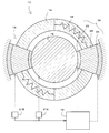
- FIG. 1 is a schematic diagram of a drive power transmission device according to an embodiment of the present invention.
- FIG. 2 is a schematic diagram explaining operation of the drive power transmission device according to the embodiment.
- FIG. 3 is a schematic diagram explaining operation of the drive power transmission device according to the embodiment.
- FIG. 4 is a schematic diagram explaining operation of the drive power transmission device according to the embodiment.
- FIG. 5 is a schematic diagram explaining operation of the drive power transmission device according to the embodiment.
- FIG. 6 is a diagram showing example results of transmission carried out by the drive power transmission device according to the embodiment.
- FIG. 7 is a diagram showing example results of transmission carried out by the drive power transmission device according to the embodiment.
- FIG. 8 is a diagram showing example results of transmission carried out by the drive power transmission device according to the embodiment.
- FIG. 1 is a schematic diagram of a drive power transmission device according to an embodiment of the present invention.
- FIG. 2 is a schematic diagram explaining operation of the drive power transmission device according to the embodiment.
- FIG. 3 is a
- FIG. 9 is a diagram showing example results of transmission carried out by the drive power transmission device according to the embodiment.
- FIG. 10 is a diagram showing example results of transmission carried out by the drive power transmission device according to the embodiment.
- FIG. 11 is a diagram showing example results of transmission carried out by a drive power transmission device according to an embodiment of the present invention.
- FIG. 12 is a schematic diagram explaining a configuration of a drive power transmission device according to an embodiment of the present invention.
- FIG. 13 is a side cross-sectional view showing the drive power transmission device according to the embodiment.
- FIG. 14 is a diagram showing example results of transmission carried out by the drive power transmission device according to the embodiment.
- FIG. 15 is a diagram showing example results of transmission carried out by the drive power transmission device according to the embodiment.
- the input shaft 12 is driven to be rotated by a drive source (not shown).
- the output shaft 14 is arranged to be spaced from the input shaft 12 while being coaxial with the input shaft 12.
- the output shaft 14 may have a hollow shape as shown in FIG. 1 with the input shaft 12 being arranged on the inside, or alternatively, as shown in FIG. 13 explained later, the output shaft 14 may be arranged coaxially and in a longitudinally adjacent relationship with the input shaft 12.
- the transmission member 16 transmits drive power of the input shaft 12 to the output shaft 14 via an elastic member 18. As described in the following, the transmission member 16 transmits drive power of the input shaft 12 to the output shaft 14 in synchronization with a vibration element 20 that is reciprocated along the shaft circumferential direction of the input shaft 12.
- a vibration element 20 that is reciprocated along the shaft circumferential direction of the input shaft 12.
- two transmission members 16 are provided on the output shaft 14 in FIG. 1, the present invention is not limited to this configuration. For example, there may be provided only one transmission member 16. Further, for achieving balance in the radial direction (i.e., as counterweights), a plurality of transmission members 16 may be provided in axial symmetry.
- the transmission member 16 includes the elastic member 18, the vibration element 20, a clutch 22, and a brake 24.
- the elastic member 18 is fixed at a fixed point on the output shaft 14, and extends along the shaft circumference at a position spaced from the central axis of the output shaft 14.
- a slot is formed along the circumferential direction, and the elastic member 18 is arranged inside this slot.
- the elastic member 18 is caused to expand and contract (i.e., effect elastic vibration) along the shaft circumference of the output shaft 14.
- the elastic member 18 may be composed of a coil spring, for example.
- One end of the elastic member 18 in the lengthwise direction is fixed to the output shaft 14, while the other end is fixed to the vibration element 20.
- the period of vibration of the elastic member 18 is shorter than the maximum period of rotation of the drive source.
- the vibration element 20 is coupled to the elastic member 18, and is caused to reciprocate in the shaft circumferential direction of the output shaft 14 in accordance with expansion and contraction of the elastic member 18.
- the vibration element 20 may be composed of a rigid material such as a metal, for example.
- the vibration element 20 may be configured as a weight that reciprocates along the slot together with the elastic member 18, or alternatively, as shown in FIG. 13 explained later, the vibration element 20 may be a transmission shaft that is arranged coaxially with the output shaft 14 and rotates about the axis in accordance with expansion and contraction of the elastic member 18.
- the clutch 22 is an engagement means for engaging the vibration element 20 with the input shaft 12.
- the clutch 22 is configured as an element that can perform operations for achieving engagement and release between the vibration element 20 and the input shaft 12 at a high speed.
- the clutch 22 is preferably an element that can perform the engaging and releasing operations in a cycle shorter than that for the frequency of vibration of the elastic member 18.
- the clutch 22 is configured, for example, as an electromagnetic clutch that performs the engaging and releasing operations by means of electric power connection and disconnection with respect to an electromagnet.
- the clutch 22 may be a one-way clutch.
- a one-way clutch actuates mechanically in response to relative velocity between the input shaft 12 and the vibration element 20.
- the brake 24 serves to lock the vibration element 20 to a fixed member (non-rotating member) such as a housing.
- the brake 24 is also configured as an element that can perform operations for achieving locking and release of the vibration element 20 at a high speed.
- the brake 24 is configured as an electromagnetic brake that performs the locking and releasing operations by means of electric power connection and disconnection with respect to an electromagnet.
- the velocity sensor 21A measures the rotational velocity (angular velocity) of the input shaft 12, and transmits the measured rotational velocity to the control unit 19.
- the velocity sensor 21B measures the movement velocity of the vibration element 20, and transmits the measured movement velocity to the control unit 19. And further, the control unit 19 may receive the movement velocity of the output shaft 14 from another velocity sensor.
- the control unit 19 controls operation of the clutch 22 and the brake 24 in accordance with the rotational velocity of the input shaft 12 and the movement velocity of the vibration element 20.
- the control unit 19 may be a computer.
- the computer may have stored therein an operation control program for the clutch 22 and the brake 24, as described in the following.
- the computer may be a built-in computer.
- the control unit 19 includes an input interface which receives input of the rotational velocity of the input shaft 12 from the velocity sensor 21A and also receives input of the movement velocity of the vibration element 20 from the velocity sensor 21B.
- the control unit 19 controls the clutch 22 and the brake 24. That is, the control unit 19 controls the clutch 22 to thereby effect engagement and release between the vibration element 20 and the input shaft 12. Further, the control unit 19 controls the brake 24 to thereby effect locking and release of the vibration element 20.
- the elastic member 18 In order to place the elastic member 18 in a vibrating state during transmission of drive power, it is preferable to configure such that the elastic member 18 is in a biased state at a stage before transmission (i.e., at a stand-by stage). For example, as shown by a dashed line in FIG. 4 explained later, the vibration element 20 and the output shaft 14 are locked while the elastic member 18 is in a contracted state.
- the clutch 22 causes the input shaft 12 and the vibration element 20 to be engaged with each other in synchronization with the period of reciprocation of the vibration element 20.
- drive power of the input shaft 12 is transmitted to the output shaft 14 in synchronization with the period of vibration of the elastic member 18.
- drive power transmission can be performed independently from the period of rotation of the input shaft 12. Further, by using an elastic member 18 having a period of vibration that is shorter than the maximum period of rotation of the drive source, transmission of drive power can be carried out over a plurality of instances during one rotation of the input shaft 12. Additionally, while the drive power transmission is carried out intermittently, by performing the intermittent transmission at a high speed (i.e., at a high frequency), smooth drive power transmission similar to that achieved by PWM control can be attained.
- the two components are caused to be engaged with each other when the velocity difference between the movement velocity of the vibration element 20 and the rotational velocity of the input shaft 12 is smaller than or equal to a predetermined value.
- the two components are caused to be engaged with each other when the velocity of one of the components is within a range from 80% to 120% of the velocity of the other component.
- engagement between the vibration element 20 and the input shaft 12 is effected when the two components have the same angular velocity.
- the angular velocity of the vibration element 20 varies in accordance with the elastic energy of the elastic member 18.
- the angular velocities of the input shaft 12 and the vibration element 20 become equal to each other at two instances.
- the clutch 22 causes the input shaft 12 and the vibration element 20 to be engaged with each other.
- the elastic member 18 When the input shaft 12 and the vibration element 20 are engaged with each other by the clutch 22, the elastic member 18 is caused to contract in accordance with the velocity difference between the input shaft 12 and the output shaft 14 (where (input shaft angular velocity) > (output shaft angular velocity)), so that elastic energy of the elastic member 18 is accumulated, as illustrated in the upper and lower diagrams in FIG. 3. In other words, drive energy of the input shaft 12 is converted into elastic energy of the elastic member 18.
- the clutch 22 is released, and the vibration element 20 is locked by the brake 24.
- the elastic member 18 transmits the accumulated elastic energy to the output shaft 14. That is to say, the elastic member 18 transmits the drive energy of the input shaft 12 as power to the output shaft 14.
- the vibration element 20 is locked, the contracted elastic member 18 rotates (pushes) the output shaft 14 in order to expand to its natural length. In this way, drive power is transmitted from the input shaft 12 to the output shaft 14.
- the drive power transmission from the input shaft 12 to the output shaft 14 via the elastic member 18 can be expressed numerically as follows. For example, in a case in which the ratio of the angular velocity of the input shaft 12 relative to the angular velocity of the output shaft 14 is 5:3, 2/5 of the input energy, which corresponds to the differential during engagement of the clutch 22, is maintained in the elastic member 18 as elastic energy, and the remaining 3/5 of the energy is transmitted to the output shaft 14.
- the control unit 19 executes control for enabling the above-described drive power transmission.
- the control unit 19 receives the rotational velocity of the input shaft 12 and the movement velocity of the vibration element 20 from the velocity sensors 21A, 21B.
- the control unit 19 instead of the measured velocities, it is also possible to use calculated values obtained by performing calculations based on values such as the natural frequencies of the input shaft 12, the output shaft 14, and the elastic member 18.
- the control unit 19 When the relative velocity between the input shaft 12 and the vibration element 20 becomes less than or equal to a predetermined velocity, the control unit 19 performs a control to engage the vibration element 20 and the input shaft 12 with each other by controlling the clutch 22 (elastic energy accumulation control). By this control, the elastic member 18 is caused to contract in accordance with the velocity difference between the input shaft 12 and the output shaft 14, so that elastic energy is accumulated in the elastic member 18.
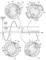
- FIG. 5 shows example changes in the velocities of the input shaft 12, the vibration element 20, and the output shaft 14 that occur during the above-described drive power transmission.
- the vibration element 20 is released from the clutch 22 and the brake 24, and is reciprocating along the shaft circumferential direction of the output shaft 14. In this state, the maximum angular velocity of the vibration element 20 is higher than the angular velocity of the input shaft 12.
- the clutch 22 causes the input shaft 12 and the vibration element 20 to be engaged with each other. During the engagement, the vibration element 20 and the input shaft 12 have the same velocity.
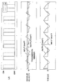
- FIG. 6 shows example changes in angular velocity and torque of the input shaft 12, the output shaft 14, and the vibration element 20.
- the "L/U" diagram in the middle row shows engagement (or “lock-up") of the clutch 22 and engagement of the brake 24.
- LU1 denotes engagement of the clutch 22, while LU2 denotes engagement of the brake 24.
- the diagram in the bottom row of FIG. 6 illustrates changes in the torque received by the input shaft 12 from the transmission member 16 (i.e., input torque, as viewed from the drive power transmission device 10), and changes in the torque received by the output shaft 14 from the transmission member 16 (i.e., torque transmitted from the transmission member 16 to the output shaft 14).
- the former torque is referred to as the input shaft torque
- the latter torque is referred to as the output shaft torque.
- the output-side angular velocity is lower than the input-side angular velocity, while the output shaft torque is greater than the input shaft torque.
- the ratio of the output-side angular velocity relative to the input-side angular velocity i.e., the transmission ratio
- the ratio of the output shaft torque relative to the input shaft torque i.e., the torque ratio
- FIG. 7 shows an example of transmission performed at transmission ratios and torque ratios that are different from those in FIG. 6.
- the graphs illustrating torque changes show the values of the output shaft torque together with its average value.
- the initial state between the input shaft 12 and the output shaft 14, the transmission ratio is 1/1.3, while the torque ratio is 1.3.
- the angular velocity of the input shaft 12 is increased (segment (2)).
- angular velocity variation (amplitude) of the vibration element 20 is increased so that the maximum angular velocity of the vibration element 20 becomes higher than the final angular velocity (200 rad/s in segment (3)) of the input shaft.
- a longer clutch 22 engagement period i.e., longer LU1
- a shorter brake 24 engagement period i.e., shorter LU2
- the clutch 22 is engaged to accumulate elastic energy of the elastic member 18. Subsequently, the clutch 22 is released and the brake 24 is engaged so as to transmit the elastic energy to the output shaft 14 (segment (3)).
- the transmission ratio is 1/2.5, while the torque ratio is 2.5.
- the transmission ratio and the torque ratio between the input shaft 12 and the output shaft 14 can be made to vary.
- variation can be effected continuously, in a non-stepwise manner.
- continuously variable transmission can be achieved using the simple structure as shown in FIG. 1.
- FIGs. 8 and 9 illustrate examples in which the same transmission ratio and torque ratio are obtained by changing conditions of the above-noted three parameters.
- the amplitude of the vibration element 20 is smaller than in FIG. 9, but the clutch 22 engagement period (LU1) and the brake 24 engagement period (LU2) are set longer than in FIG. 9. Even when conditions of the amplitude of the vibration element 20, the clutch 22 engagement period, and the brake 24 engagement period are changed in various ways as such, the same transmission ratio and torque ratio can be obtained.
- FIG. 10 shows output shaft torque changes that are generated when the clutch 22 engagement period is changed. According to FIG. 10, the range of variation in the output shaft torque becomes reduced as the clutch 22 engagement period is made longer.
- the clutch 22 engagement period is preferably long.
- the clutch 22 engagement period must inevitably be made shorter, as shown in FIG. 9.
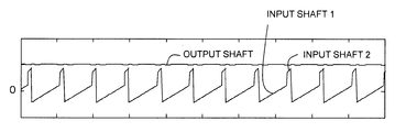
- FIG. 11 illustrates torque changes generated when two drive power transmission devices 10 are provided coaxially and in a side-by-side relationship with the input shaft 12. The input shaft torque becomes multi-phased, and as a result, the output shaft torque is smoothed out.
- the control unit 19 executes continuously variable transmission control as described above.
- the control unit 19 comprises an input interface (or signal line) for inputting a required transmission ratio and a required torque ratio (i.e., requirement information) which are required of the input shaft 12 by the output shaft 14.
- a memory unit (not shown) has stored therein a table in which transmission ratio and torque ratio are correlated with amplitude of the vibration element 20, clutch 22 engagement period, and brake 24 engagement period. This table can be obtained by actually measuring or calculating the correlations indicating what transmission ratio and torque ratio between the input shaft 12 and the output shaft 14 are obtained when amplitude of the vibration element 20, clutch 22 engagement period, and brake 24 engagement period are changed in various ways. Instead of the table, an algorithm or function corresponding to the table may be stored.
- the control unit 19 refers to the table based on the required transmission ratio and the required torque ratio input via the input interface, and thereby acquires an amplitude of the vibration element 20, a clutch 22 engagement period, and a brake 24 engagement period. Subsequently, based on the acquired amplitude of the vibration element 20, clutch 22 engagement period, and brake 24 engagement period, the control unit 19 controls the clutch 22 and the brake 24.
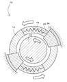
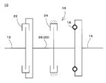
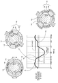
- FIG. 12 shows a schematic diagram depicted by extracting main elements from among specific structural elements of the drive power transmission device 10.
- a transmission member 16 and an output shaft 14 are located along the axial direction of an input shaft 12.
- the transmission member 16 comprises a clutch 22, a brake 24, an elastic member 18, and a transmission shaft 26.
- the clutch 22 is provided at an axial end of the transmission shaft 26 so as to be engageable with a flange located at an axial end of the input shaft 12.
- the brake 24 is provided at an axially central portion of the transmission shaft 26, the brake 24 is provided.
- the elastic member 18 is provided at an end of the transmission shaft 26 opposite from the end at which the clutch 22 is disposed.
- the elastic member 18 is coupled to the transmission shaft 26, and the transmission shaft 26 is reciprocated in the shaft circumferential direction in accordance with vibration of the elastic member 18. As such, the transmission shaft 26 corresponds to the vibration element 20 in FIG. 1 and other figures.
- FIG. 13 shows an example of a specific structure according to the configuration of FIG. 12.
- the input shaft 12, the transmission shaft 26, and the output shaft 14 are arranged coaxially.
- the input shaft 12 and the transmission shaft 26 are rotatably supported on a base 30 via bearings 28.
- a flange 32 is formed radially extending from the input shaft 12.
- the magnetizing part 22B receives a magnetizing current from a power source (now shown) and thereby generates magnetic flux.
- the magnetizing part 22B is an annular member that is fixed to the base 30 while being spaced from the input shaft 12 and the transmission shaft 26.
- the movable part 22A is an annular member composed of a magnetic material such as a metal, and is movable in response to magnetic flux generated from the magnetizing part 22B.
- the movable part 22A is coupled to the transmission shaft 26 via a fastening member 34 screwed into the movable part 22A in the axial direction.
- a shaft part 36 of the fastening member 34 is formed to have a length greater than the axial thickness of an input-side flange 38 of the transmission shaft 26.
- the transmission shaft 26 comprises the input-side flange 38, a mid flange 40, and an output-side flange 42. These flanges are formed on the transmission shaft 26 sequentially along the axial direction from the input shaft 12 toward the output shaft 14. When the movable part 22A of the clutch 22 provided on the input-side flange 38 engages with the input shaft 12, the transmission shaft 26 rotates synchronously with the input shaft 12.
- the elastic member 18 is coupled to the output-side flange 42.
- the elastic member 18 is arranged in a slot 44 extending along the shaft circumference of the output shaft 14.
- One end of the elastic member 18 in the extending direction of the slot 44 is coupled to the output-side flange 42, while the other end is coupled to the output shaft 14.
- the brake 24 is provided at the mid flange 40.
- the brake includes a movable part 24A and a magnetizing part 24B, which are disposed on respective sides of the mid flange 40.
- the movable part 24A is movable relative to the base 30 in the axial direction only.
- the magnetizing part 24B When magnetic flux is generated in the magnetizing part 24B, the movable part 24A is attracted in the axial direction and engages with the transmission shaft 26. As a result, rotation of the transmission shaft 26 is stopped.
- Drive power transmission from the input shaft 12 to the output shaft 14 is carried out as described in the following.
- the present invention is not limited to this form of drive power transmission.
- the drive power transmission device 10 of the present embodiment can also perform drive power transmission when the rotational velocity of the input shaft 12 is lower than the rotational velocity of the output shaft 14.
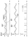
- FIGs. 14 and 15 show timing charts regarding drive power transmission performed when the rotational velocity of the input shaft 12 is lower than the rotational velocity of the output shaft 14. In FIG.
- engagement and release of the clutch 22 are effected during acceleration of the vibration element 20 (i.e., when (spring extension) ⁇ (natural length)), and locking and release by the brake 24 are effected during deceleration of the vibration element 20 (i.e., when (spring extension) > (natural length)).
- engagement and release of the clutch 22 are effected during acceleration of the vibration element 20
- locking by the brake 24 is effected also during acceleration of the vibration element
- release of the brake 24 is effected also during acceleration of the vibration element 20.
- the drive power transmission device 10 functions as an overdrive device.
- the relative velocity between the vibration element 20 and the output shaft 14 becomes zero. That is, the elastic member 18 expands fully, and the vibration velocity of the vibration element 20 becomes zero. Subsequently, the vibration element 20 is caused to move in the contracting direction of the elastic member 18; i.e., in the rotation direction of the output shaft 14. At time t2, the elastic member 18 assumes its natural length (i.e., the length of the elastic member 18 when the amplitude velocity component of the vibration element 20 has the maximum value). After the elastic member 18 contracts fully at time t3, the vibration element 20 is caused to move in the expanding direction of the elastic member 18; i.e., in the direction opposite to the rotation direction of the output shaft 14.
- the absolute velocity of the vibration element 20 i.e., the combined velocity of the vibration of the elastic member 18 and the rotation of the output shaft 14
- the vibration element 20 and the input shaft 12 are caused to be engaged with each other. As the relative velocity between these two components is zero, no slipping occurs in principle.
- the elastic member 18 When the engagement by the clutch is released at time t5, the elastic member 18, which is still in the course of expansion, rotates in the direction opposite to the rotation of the output shaft 14.
- the elastic member 18 expands to a length longer than its natural length (t6), and subsequently when the absolute velocity of the vibration element 20 (i.e., the combined velocity of the vibration of the elastic member 18 and the rotation of the output shaft 14) becomes zero (t7), the vibration element 20 is anchored via the brake 24 to a fixed member (non-rotating member) such as the housing.
- a fixed member non-rotating member
- the elastic member 18 which is in the expanded state with a length longer than its natural length (i.e., in a state capable of urging the output shaft 14 in the direction opposite to its rotation direction), is further expanded by being urged by the output shaft 14 (time t7 to t8).
- elastic energy for urging in the direction opposite to the rotation direction of the output shaft 14 is transmitted from the output shaft 14 to the elastic member 18.
- the process continues with operation corresponding to that at time t1 (which is equivalent to t9).
- the input shaft 12 and the elastic member 18 transmit torque to the output shaft 14 during the period from time t4 to t5, and at least a part of the torque transmitted from the elastic member 18 is returned from the output shaft 14 to the elastic member 18 during the period from time t7 to t8. That is to say, in the present embodiment, torque transmission from the input shaft 12 to the output shaft 14 is carried out via energy cancellation between transmitted elastic energy of the elastic member 18 and transmitted torque of the output shaft 14.
- timings of engagement of the clutch 22 and the brake 24 in the embodiment of FIG. 18 need not be limited to the point at which there is an exact match between the absolute velocity of the vibration element 20 and the rotational velocity of the input shaft 12, and the point at which the absolute velocity of the vibration element 20 becomes exactly zero.
- the timings are sufficient so long as the magnitude of loss due to slipping can be considered ignorable relative to the input and output energy.
- engagement between the two engaged components may be effected when the velocity of one of the components is within a range from 80% to 120% of the velocity of the other component.
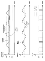
- FIGs. 19 and 20 illustrate further example results of motive power transmission carried out by a drive power transmission device 10 according to an embodiment of the present invention.
- the example shown relates to a case of motive power transmission performed when the input shaft 12 and the output shaft 14 are rotating in directions counter to each other.
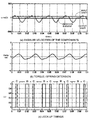
- FIG. 19 shows timing charts for the drive power transmission device 10.
- the graph in the top row illustrates transitions in the angular velocities of the input shaft 12, the vibration element 20, and the output shaft 14.
- the vertical axis indicates angular velocity, while the horizontal axis indicates time.
- the input shaft 12 and the output shaft 14 have angular velocities that appear on the respective sides of the zero velocity line, and it can be understood that the two shafts are mutually counter-rotating.
- the graph in the middle row of FIG. 19 illustrates torque of the output shaft 14 and expansion of the elastic member 18.
- the vertical axis indicates vibration displacement of the elastic member 18. By multiplying the vibration displacement by a spring constant, output torque of the output shaft 14 is obtained.
- the horizontal axis indicates time in synchronization with the top row graph.
- the graph in the bottom row of FIG. 19 illustrates the timings of engagement (lock-up timings) of the clutch 22 (C) and the brake 24 (B) of the transmission member 16.
- the horizontal axis indicates time in synchronization with the top and middle row graphs.
- FIG. 20 shows an enlarged view of a portion extracted from the top row graph in FIG. 19, the portion corresponding to one cycle of motive power transmission by the transmission member 16.
- the starting point is time t11, at which the absolute velocity of the vibration element 20 (i.e., the combined velocity of the vibration of the elastic member 18 and the rotation of the output shaft 14) becomes zero.
- the elastic member 18 contracts, so that the vibration element 20 moves in the same direction as the input shaft 12 (first rotation shaft).
- the elastic member 18 assumes its natural length (i.e., the length of the elastic member 18 when the amplitude velocity component of the vibration element 20 has the maximum value).
- the elastic member 18 contracts further so that the vibration element 20 decelerates, and, at time t13, the absolute velocity of the vibration element 20 becomes equal to the rotational velocity of the input shaft 12. At that point, by means of the clutch 22, the vibration element 20 and the input shaft 12 are caused to be engaged with each other (first state). As the relative velocity between these two components is zero, no slipping occurs in principle.
- the elastic member 18 Since the input shaft 12 and the output shaft 14 (second rotation shaft) are mutually counter-rotating, when the vibration element 20 and the input shaft 12 are engaged with each other, the elastic member 18, which is in a contracted state with a length shorter than its natural length (i.e., in a state capable of urging the second rotation shaft 14 in the opposite direction from the rotation direction of the second rotation shaft 14), is contracted further by the torque of the two shafts 12, 14. In other words, elastic energy is accumulated in the elastic member 18 by means of the urging by the input shaft 12 and the output shaft 12 (time t13 to t14).
- the elastic member 18 contracts further, and, at time t15, the velocity of the vibration element 20 becomes equal to the velocity of the output shaft 14. That is, the elastic member 18 contracts fully, and the vibration velocity of the vibration element 20 becomes zero. Subsequently, due to expanding motion of the elastic member 18, the vibration element 20 is caused to move in the direction opposite to the rotation of the input shaft 12 (i.e., in the same direction as the output shaft 14). At time t16, the elastic member 18 assumes its natural length, and the vibration element 20 is further caused to move in the expanding direction of the elastic member 18, which corresponds to the rotation direction of the output shaft 14.
- the vibration element 20 When the absolute velocity of the vibration element 20 becomes zero at time t17, the vibration element 20 is anchored via the brake 24 to a fixed member (non-rotating member) such as the housing (third state). As the relative velocity between the two components (the vibration element 20 and the housing) is zero, no slipping occurs in principle.
- the elastic member 18 which has expanded to a length beyond its natural length (i.e., which is in a state capable of urging the second rotation shaft 14 in the rotation direction of the second rotation shaft 14), contracts so as to pull the output shaft 14 (time t17 to t18).
- the elastic energy of the elastic member 18 serves as torque in the same direction as the rotation direction of the output shaft 14, and thereby urges the output shaft 14.
- the elastic energy of the elastic member 18 is released to the output shaft 14.
- the engagement of the brake 24 is released, and the process continues with operation corresponding to that at time t11 (which is equivalent to t18).
- timings of engagement of the clutch 22 and the brake 24 in the embodiment of FIGs. 19 and 20 need not be limited to the point at which there is an exact match between the absolute velocity of the vibration element 20 and the rotational velocity of the input shaft 12, and the point at which the absolute velocity of the vibration element 20 becomes exactly zero.
- the timings are sufficient so long as the magnitude of loss due to slipping can be considered ignorable relative to the input and output energy.
- engagement between the two engaged components may be effected when the velocity of one of the components is within a range from 80% to 120% of the velocity of the other component.
- FIGs. 16 and 17 show timing charts regarding drive power transmission performed with a configuration in which the elastic member 18 and the vibration element 20 are provided on the input shaft 12 instead of the output shaft 14.
- FIGs. 16 and 17 illustrate examples in which the rotational velocity of the input shaft 12 is higher than the rotational velocity of the output shaft 14.
- engagement and release of the clutch 22 are effected during acceleration of the vibration element 20, and locking and release by the brake 24 are effected during deceleration of the vibration element 20.
- FIG. 17 engagement and release of the clutch 22 are effected during acceleration of the vibration element 20, locking by the brake 24 is effected during deceleration of the vibration element 20, and release of the brake 24 is effected during acceleration of the vibration element 20.
Landscapes
- Engineering & Computer Science (AREA)
- General Engineering & Computer Science (AREA)
- Mechanical Engineering (AREA)
- Hydraulic Clutches, Magnetic Clutches, Fluid Clutches, And Fluid Joints (AREA)
- Transmission Devices (AREA)
Abstract
L'invention concerne un dispositif de transmission de puissance d'entraînement qui peut transmettre de manière asynchrone une puissance d'entraînement avec la rotation d'un arbre d'entrée. Le dispositif de transmission de puissance d'entraînement (10) comprend un premier arbre de rotation (12), un second arbre de rotation (14), un élément élastique (18) et un élément vibrant (20). Une extrémité de l'élément élastique (18) est fixée au second arbre de rotation (14) à une position espacée de son axe central tandis que l'autre extrémité de l'élément élastique (18) est fixée à l'élément vibrant (20). L'élément vibrant (20) peut être placé soit dans un premier état dans lequel il est raccordé au premier arbre de rotation (12), soit dans un second état dans lequel il est désolidarisé du premier arbre de rotation (12).
Priority Applications (3)
| Application Number | Priority Date | Filing Date | Title |
|---|---|---|---|
| US15/105,968 US10408315B2 (en) | 2013-12-20 | 2014-12-17 | Drive power transmission device and control program therefor |
| EP14827873.2A EP3084265B1 (fr) | 2013-12-20 | 2014-12-17 | Dispositif de transmission de puissance d'entraînement et son programme de commande |
| CN201480069789.4A CN105917140B (zh) | 2013-12-20 | 2014-12-17 | 驱动力传输装置及其控制程序 |
Applications Claiming Priority (6)
| Application Number | Priority Date | Filing Date | Title |
|---|---|---|---|
| JP2013-264150 | 2013-12-20 | ||
| JP2013264150 | 2013-12-20 | ||
| JP2014240170A JP6319063B2 (ja) | 2014-11-27 | 2014-11-27 | 駆動力伝達装置及びその制御用プログラム |
| JP2014-240170 | 2014-11-27 | ||
| JP2014-240169 | 2014-11-27 | ||
| JP2014240169A JP6183337B2 (ja) | 2013-12-20 | 2014-11-27 | 駆動力伝達装置及びその制御用プログラム |
Publications (2)
| Publication Number | Publication Date |
|---|---|
| WO2015093055A2 true WO2015093055A2 (fr) | 2015-06-25 |
| WO2015093055A3 WO2015093055A3 (fr) | 2015-10-01 |
Family
ID=52355121
Family Applications (1)
| Application Number | Title | Priority Date | Filing Date |
|---|---|---|---|
| PCT/JP2014/006308 Ceased WO2015093055A2 (fr) | 2013-12-20 | 2014-12-17 | Dispositif de transmission de puissance d'entraînement et son programme de commande |
Country Status (1)
| Country | Link |
|---|---|
| WO (1) | WO2015093055A2 (fr) |
Cited By (3)
| Publication number | Priority date | Publication date | Assignee | Title |
|---|---|---|---|---|
| JP2016075352A (ja) * | 2014-10-07 | 2016-05-12 | 株式会社豊田中央研究所 | 駆動力伝達装置の制御装置、制御方法及びプログラム |
| KR20180031691A (ko) * | 2015-07-21 | 2018-03-28 | 베일렌만 마틴 | 토션 스프링을 가지는 변속기 및 변속기의 작동방법 |
| CN109058408A (zh) * | 2018-08-16 | 2018-12-21 | 西安工业大学 | 一种可伸缩式多功能机械间歇传动装置 |
Families Citing this family (1)
| Publication number | Priority date | Publication date | Assignee | Title |
|---|---|---|---|---|
| CN106015493B (zh) * | 2016-07-18 | 2018-10-26 | 浙江机电职业技术学院 | 一种可实现间歇运动的机构 |
Citations (1)
| Publication number | Priority date | Publication date | Assignee | Title |
|---|---|---|---|---|
| JP2012251619A (ja) | 2011-06-03 | 2012-12-20 | Honda Motor Co Ltd | 車両用動力伝達装置 |
Family Cites Families (2)
| Publication number | Priority date | Publication date | Assignee | Title |
|---|---|---|---|---|
| DE2839824A1 (de) * | 1978-09-11 | 1980-03-20 | Eberhard Dipl Phys D Fiukowski | Automatisches getriebe |
| CZ305914B6 (cs) * | 2010-03-29 | 2016-05-04 | VĂšTS, a.s. | Způsob a zařízení ke snížení negativních účinků dynamických sil mechanické soustavy |
-
2014
- 2014-12-17 WO PCT/JP2014/006308 patent/WO2015093055A2/fr not_active Ceased
Patent Citations (1)
| Publication number | Priority date | Publication date | Assignee | Title |
|---|---|---|---|---|
| JP2012251619A (ja) | 2011-06-03 | 2012-12-20 | Honda Motor Co Ltd | 車両用動力伝達装置 |
Cited By (5)
| Publication number | Priority date | Publication date | Assignee | Title |
|---|---|---|---|---|
| JP2016075352A (ja) * | 2014-10-07 | 2016-05-12 | 株式会社豊田中央研究所 | 駆動力伝達装置の制御装置、制御方法及びプログラム |
| KR20180031691A (ko) * | 2015-07-21 | 2018-03-28 | 베일렌만 마틴 | 토션 스프링을 가지는 변속기 및 변속기의 작동방법 |
| JP2018521285A (ja) * | 2015-07-21 | 2018-08-02 | マルティン、バイレンマンMartin Weilenmann | ねじりばねを有するトランスミッション、及びトランスミッションを操作するための方法 |
| KR102558376B1 (ko) * | 2015-07-21 | 2023-07-20 | 베일렌만 마틴 | 토션 스프링을 가지는 변속기 및 변속기의 작동방법 |
| CN109058408A (zh) * | 2018-08-16 | 2018-12-21 | 西安工业大学 | 一种可伸缩式多功能机械间歇传动装置 |
Also Published As
| Publication number | Publication date |
|---|---|
| WO2015093055A3 (fr) | 2015-10-01 |
Similar Documents
| Publication | Publication Date | Title |
|---|---|---|
| EP3084265B1 (fr) | Dispositif de transmission de puissance d'entraînement et son programme de commande | |
| JP6183337B2 (ja) | 駆動力伝達装置及びその制御用プログラム | |
| WO2015093055A2 (fr) | Dispositif de transmission de puissance d'entraînement et son programme de commande | |
| RU2019142113A (ru) | Способ приведения в действие трансмиссии | |
| US11168771B2 (en) | Drive force transmission device | |
| US9482305B2 (en) | Dynamic damper device | |
| JP2013158116A (ja) | 制御装置 | |
| JP6830729B2 (ja) | 回転慣性質量ダンパの制御装置 | |
| JP6256409B2 (ja) | 駆動力伝達装置及びその制御用プログラム | |
| JP6319063B2 (ja) | 駆動力伝達装置及びその制御用プログラム | |
| EP2360396B1 (fr) | Système de transmission à variation continue | |
| KR20180031691A (ko) | 토션 스프링을 가지는 변속기 및 변속기의 작동방법 | |
| JP6311735B2 (ja) | 駆動力伝達装置、駆動力伝達装置の制御方法及びプログラム | |
| US2248444A (en) | Variable ratio mechanical drive mechanism | |
| JP6682939B2 (ja) | 駆動力伝達装置 | |
| JP6327097B2 (ja) | 駆動力伝達装置の制御装置、制御方法及びプログラム | |
| CN113530674B (zh) | 包括用于使用固定式致动器改变发动机组件的压缩比的齿轮箱的发动机组件 | |
| JP6477028B2 (ja) | 動力伝達装置 | |
| US20200355226A1 (en) | Meshing engagement device and controller | |
| JP6157403B2 (ja) | 車両用動力伝達装置 | |
| JP6361017B2 (ja) | モータ駆動装置の指令生成方法 | |
| JP6080220B2 (ja) | 車両用動力伝達装置 | |
| JP2025037742A (ja) | 駆動装置 | |
| US20150159637A1 (en) | Inertial traction system | |
| JP2017057924A (ja) | 回転伝達装置 |
Legal Events
| Date | Code | Title | Description |
|---|---|---|---|
| DPE1 | Request for preliminary examination filed after expiration of 19th month from priority date (pct application filed from 20040101) | ||
| WWE | Wipo information: entry into national phase |
Ref document number: 15105968 Country of ref document: US |
|
| NENP | Non-entry into the national phase |
Ref country code: DE |
|
| REEP | Request for entry into the european phase |
Ref document number: 2014827873 Country of ref document: EP |
|
| WWE | Wipo information: entry into national phase |
Ref document number: 2014827873 Country of ref document: EP |
|
| 121 | Ep: the epo has been informed by wipo that ep was designated in this application |
Ref document number: 14827873 Country of ref document: EP Kind code of ref document: A2 |