WO2015097786A1 - ウェイストゲートバルブ装置 - Google Patents
ウェイストゲートバルブ装置 Download PDFInfo
- Publication number
- WO2015097786A1 WO2015097786A1 PCT/JP2013/084672 JP2013084672W WO2015097786A1 WO 2015097786 A1 WO2015097786 A1 WO 2015097786A1 JP 2013084672 W JP2013084672 W JP 2013084672W WO 2015097786 A1 WO2015097786 A1 WO 2015097786A1
- Authority
- WO
- WIPO (PCT)
- Prior art keywords
- waste gate
- gate valve
- valve device
- waste
- exhaust gas
- Prior art date
- Legal status (The legal status is an assumption and is not a legal conclusion. Google has not performed a legal analysis and makes no representation as to the accuracy of the status listed.)
- Ceased
Links
Images





Classifications
-
- F—MECHANICAL ENGINEERING; LIGHTING; HEATING; WEAPONS; BLASTING
- F02—COMBUSTION ENGINES; HOT-GAS OR COMBUSTION-PRODUCT ENGINE PLANTS
- F02B—INTERNAL-COMBUSTION PISTON ENGINES; COMBUSTION ENGINES IN GENERAL
- F02B37/00—Engines characterised by provision of pumps driven at least for part of the time by exhaust
- F02B37/12—Control of the pumps
- F02B37/18—Control of the pumps by bypassing exhaust from the inlet to the outlet of turbine or to the atmosphere
- F02B37/183—Arrangements of bypass valves or actuators therefor
- F02B37/186—Arrangements of actuators or linkage for bypass valves
-
- F—MECHANICAL ENGINEERING; LIGHTING; HEATING; WEAPONS; BLASTING
- F02—COMBUSTION ENGINES; HOT-GAS OR COMBUSTION-PRODUCT ENGINE PLANTS
- F02B—INTERNAL-COMBUSTION PISTON ENGINES; COMBUSTION ENGINES IN GENERAL
- F02B37/00—Engines characterised by provision of pumps driven at least for part of the time by exhaust
- F02B37/12—Control of the pumps
- F02B37/18—Control of the pumps by bypassing exhaust from the inlet to the outlet of turbine or to the atmosphere
- F02B37/183—Arrangements of bypass valves or actuators therefor
-
- Y—GENERAL TAGGING OF NEW TECHNOLOGICAL DEVELOPMENTS; GENERAL TAGGING OF CROSS-SECTIONAL TECHNOLOGIES SPANNING OVER SEVERAL SECTIONS OF THE IPC; TECHNICAL SUBJECTS COVERED BY FORMER USPC CROSS-REFERENCE ART COLLECTIONS [XRACs] AND DIGESTS
- Y02—TECHNOLOGIES OR APPLICATIONS FOR MITIGATION OR ADAPTATION AGAINST CLIMATE CHANGE
- Y02T—CLIMATE CHANGE MITIGATION TECHNOLOGIES RELATED TO TRANSPORTATION
- Y02T10/00—Road transport of goods or passengers
- Y02T10/10—Internal combustion engine [ICE] based vehicles
- Y02T10/12—Improving ICE efficiencies
Definitions
- the present invention relates to a waste gate valve device that regulates the inflow of exhaust gas to a turbine by diverting part of the exhaust gas in a turbocharged turbocharged engine.
- a waste gate passage bypassing a turbine is formed into a tapered shape expanding from the inlet side toward the outlet side, and a valve body (waste gate valve) closing the outlet of the waste gate passage is used as a waste gate valve.
- a waste gate valve device provided with a protrusion having a height flush with the inlet side wall surface of the waste gate flow path when the gate flow path is closed. According to this waste gate valve device, when the valve body blocks the waste gate passage, the upper surface of the projection becomes the same as the inlet side wall surface of the waste gate passage, and the disturbance of the exhaust gas flow on the inlet side of the turbine can be suppressed.
- the waste gate flow path is tapered so as to expand from the inlet side to the outlet side, the gap between the side surface of the protrusion and the inner circumferential surface of the waste gate flow path is large even when the valve body is slightly opened. Thus, the opening area of the waste gate channel can be increased.
- Patent Document 2 describes a waste gate valve device in which a tapered portion is provided on the outlet side of a waste gate flow passage that bypasses a turbine so that the flow passage cross-sectional area gradually expands.
- a pressure reduction region for accelerating the flow of exhaust gas bypassing the turbine is formed between the taper portion and the valve body (waste gate valve), and the acting force on the valve body, in particular It can be reduced.
- Patent Document 3 a waste gate provided with a protrusion formed in a cross-sectional shape + on a surface (a surface on the seating side) facing the waste gate flow passage of a valve body (waste gate valve) for closing an outlet of the waste gate flow passage.
- a valve arrangement is described. According to this waste gate valve device, the flow of the exhaust gas flowing between (the gap) between the valve body and the valve seat (outlet) slightly opened at the outlet of the waste gate flow path is disturbed, so that the valve body and the valve seat The negative pressure generated in the gap between the
- the present invention is made in view of the above-mentioned subject, and an object of the present invention is to provide a waste gate valve device with good flow controllability at the time of slight opening.
- the present invention comprises a turbine housing provided with a waste gate flow passage through which exhaust gas bypasses a turbine, and a waste gate valve for opening and closing an outlet of the waste gate flow passage, and the waste gate valve is the waste gate valve.
- a waste gate valve device comprising: a valve body for opening and closing an outlet of the flow path; and a protrusion to be accommodated in the waste gate flow path when the valve body blocks the outlet of the waste gate flow path,
- the waste gate flow passage secures the maximum flow rate of exhaust gas at the time of full opening of the waste gate valve, and the flow sectional area ratio of the waste gate flow passage to the merging portion where exhaust gases passing through the turbine merge is 0.2. Further, the flow path cross-sectional area is enlarged at the outlet of the waste gate flow path. Characterized in that a widened portion.
- the flow rate of the exhaust gas flowing through the waste gate flow passage increases, so the flow passage cross-sectional area of the waste gate flow passage can be reduced by the amount of the increase.
- the controllability of the flow rate of the exhaust gas at the time of the slight opening of the waste gate valve is improved.
- passage diameter D 1 of the said waste gate channel it is preferable to satisfy the following equation 1 in relation to the channel diameter D 2 of the joint portion.
- the diameter D 3 out of the expanding portion it is preferable to satisfy the following Equation 2 in relation to the channel diameter D 1 of the said wastegate passage.
- the pressure receiving portion receives the pressure of the exhaust gas flowing through the waste gate flow path in a region close to an axis supporting the waste gate valve when the waste gate valve is opened. It is preferable to have the suppression part which suppresses the flow of the waste gas which flows through the said waste gate channel in the area
- the pressure receiving portion is formed in a region near the axis, and the suppressing portion is formed in a region far from the axis.
- the pressure receiving portion receives the pressure of the exhaust gas in the region near the axis, and the suppressing portion can suppress the flow of the exhaust gas on the side far from the axis.
- the pressure receiving portion is formed in an arc shape forming a recess between the pressure receiving portion and the suppression portion. In this way, the pressure of the exhaust gas can be efficiently received by the recess.
- the protrusion preferably has a recess for receiving the exhaust gas flowing through the waste gate channel. In this way, the pressure of the exhaust gas can be efficiently received by the recess.
- the base of the protrusion has an enlarged portion that expands along the inner periphery of the expanded portion. In this way, the occurrence of stress concentration between the protrusion and the valve body can be avoided.
- the outer peripheral end on the seating side of the valve body is preferably a curved surface. In this way, the exhaust gas flowing through the waste gate flow path smoothly flows through the outer peripheral end of the valve body, and the load acting on the waste gate valve can be reduced.
- the valve body has an elastic deformation portion that bends the tip portion between the tip portion that opens and closes the waste gate channel and the base. In this way, when the waste gate valve blocks the outlet of the waste gate flow path, the tip of the valve body bends, and the seal performance of the waste gate valve can be secured.
- a drive shaft to which the waste gate valve is fixed, and a bush for supporting the drive shaft, and a tapered surface is formed on the inner circumferential surface of the bush. In this way, it is possible to eliminate the situation in which the drive shaft is not in contact with the bush and to prevent the generation of edge surface pressure.
- a drive shaft having the waste gate valve fixed at one end, a bush for supporting the drive shaft, a lever pin provided at the other end of the drive shaft, and a rod connected to the lever pin
- the lever pin and the actuator are disposed such that the pressure direction acting on the waste gate valve coincides with the actuation direction of the actuator.
- the pressure direction of the exhaust gas acting on the waste gate valve coincides with the actuation direction of the actuator. This can prevent the drive shaft from tilting in the bush.
- the pressure loss of the exhaust gas flowing through the waste gate passage is reduced, and the flow rate of the exhaust gas is increased accordingly. Therefore, the flow passage cross-sectional area of the waste gate flow passage can be reduced by an amount corresponding to the increase in the flow rate of the exhaust gas. Thereby, the flow controllability at the time of the slight opening of the waste gate valve can be improved.
- FIG. 1 is a conceptual diagram for explaining a waste gate valve according to an embodiment of the present invention.
- FIG. 2 is a diagram showing a model of flow path enlargement.
- FIG. 3 is a diagram showing the relationship between the area ratio and the coefficient ⁇ of the experimental equation, and
- FIG. 4 is a diagram showing the relationship between the area ratio and the coefficient ⁇ of the experimental equation.
- the waste gate valve device 1 adjusts the inflow of the exhaust gas to the turbine by diverting a part of the exhaust gas in the turbocharged turbocharged engine.
- the waste gate valve device 1 includes a turbine housing 3 provided with a waste gate flow path 2 for exhaust gas bypassing a turbine (not shown), and a waste gate valve for opening and closing the waste gate flow path 2 And 4).
- the waste gate valve 4 is fixed to the drive shaft 6 via the lever 5, and pivots about an axis passing through the center of the drive shaft 6 to open and close the waste gate flow path 2.
- the waste gate valve 4 according to the present embodiment includes the valve body 7 for opening and closing the outlet of the waste gate channel 2 and the waste gate channel 2 when the valve body 7 blocks the outlet of the waste gate channel 2.
- the exhaust gas having flowed through the waste gate flow path 2 merges with the exhaust gas flowing through the turbine downstream of the waste gate flow path 2 so that the flow path cross-sectional area of the exhaust gas flowing through the waste gate flow path 2 is rapidly expanded. It is known that the rapid expansion of the flow path cross section of the exhaust gas causes the pressure loss, but the knowledge about this is reported in the Research Report of the Research Committee on High Speed Flow in the Gas Body of the Japan Society of Mechanical Engineers (1978) Is indicated.
- an expanded surface pressure P f is proposed as a parameter of the pressure loss of the flow path rapid expansion.
- the expansion surface pressure P f becomes smaller as the flow path is expanded more rapidly, and as the value (the expansion surface pressure P f ) becomes a smaller value, the flow of exhaust gas is disturbed, and the pressure loss becomes larger.
- the enlarged surface pressure P f is expressed by the following empirical formula (Formula 3).
- the enlargement surface pressure P f is influenced by the coefficient ⁇ and the coefficient ⁇ .
- the flared portion 2A is provided at the outlet of the waste gate channel 2 whose area ratio ⁇ (A 1 / A 2 ) is 0.22, the area ratio ⁇ (A 3 / A 2) Is 0.22 or more, as shown in FIG. 1, the effect of reducing the flow path (reducing the pressure loss) is reduced.
- the position of the inflection point is 0.22 as shown in FIG.
- the diameter D 1 can be obtained by the following equation 5.
- a 1 (D 1/ 2) ⁇ 2 ⁇ ⁇
- a 2 (D 2/2) ⁇ 2 ⁇ ⁇
- a 3 (D 3/2) ⁇ 2 ⁇ because it is [pi, A 1 / A 2 ⁇ 0.2 ⁇ D 1 ⁇ 0.447 D 2 A 3 / A 2 ⁇ 0.22 ⁇ D 3 ⁇ 0.469 D 2 D 3 ⁇ D 1 ⁇ (0.469 ⁇ 0.447) D 2 D 3 ⁇ D 1 0.020.022 ⁇ D 2 D 3 -D 1 ⁇ 0.022 ⁇ D 1 /0.447 D 3 ⁇ D 1 0.040.049 D 1
- Equation 6 the relationship of the diameter D 3 out of the expanding portion 2A for D 1 (larger width) is represented by Equation 6 below.
- FIG. 5 is a schematic view showing a waste gate valve device according to Embodiment 1 of the present invention.
- 6 is a view showing the relationship between the opening degree of the waste gate valve in the waste gate valve device shown in FIG. 5 and the mass flow rate of the exhaust gas flowing through the waste gate flow passage, and
- FIG. 7 is shown in FIG. It is a figure which shows the relationship between the opening degree of the waste gate valve in the waste gate valve apparatus, and the load which acts on the axis
- the waste gate valve device 11 includes a turbine housing 13 provided with a waste gate flow passage 12 for bypassing a turbine (not shown), and a waste gate flow passage. It is comprised by the waste gate valve 14 which opens and closes 12.
- the waste gate valve 14 is fixed to the drive shaft 16 via the lever 15, and the waste gate channel 12 is opened and closed by pivoting about an axis passing through the center of the drive shaft 16. As a result, in the state where the waste gate valve 14 is open, the flow path is narrow on the side close to the drive shaft 16 and widen on the side far from the drive shaft 16.
- the diameter D 1 of the waste gate passage 12 satisfies the above-mentioned equation 7 while securing the maximum flow rate of the exhaust gas when the waste gate valve 14 is fully opened.
- the exhaust gas flowing through the waste gate passage 12 and the turbine When the diameter D 2 (see FIG. 1) of the merging portion where the exhaust gas flowing through is joined is 100 mm, the diameter D 1 of the waste gate passage 12 is set to 44.6 mm or less, for example, 40 mm . Accordingly, the diameter D 1 of the waste gate passage 12 according to the first embodiment is smaller than that of the conventional, the drive shaft 16 for driving the waste gate valve 14 is installed in the same position as that of the conventional. As a result, the position of the waste gate passage 12 approaches the drive shaft 16.
- Expanding portion 12A is for enlarging the flow path cross-sectional area of the waste gate passage 12, bore D 3 out of the expanding portion 12A is intended to satisfy the equation 6 described above, for example, a waste gate passage when the diameter D 1 of the 12 is 40mm, the diameter D 3 out of the expanding portion 12A is more 41.96Mm, for example, is set to 42mm.
- the spread portion 12A is gradually spread as shown in FIG.
- the cross section is gradually expanded so as to form a curve (R).
- the cross section may be gradually expanded so as to form oblique lines.
- the waste gate valve 14 includes the valve body 17 for opening and closing the outlet of the waste gate flow path 12 and the waste gate flow path when the valve body 17 blocks the waste gate flow path 12. And a projection 18 housed in 12.
- the valve body 17 is formed in a disk shape having a size sufficient to close the outlet of the waste gate channel 12 (the outlet of the spread portion 12A).
- the projection 18 is formed in a truncated cone shape, and as described above, when the valve body 17 blocks the outlet of the waste gate flow path 12, it is accommodated in the waste gate flow path 12, while the valve body 17 is waste gate flow Even when the passage 12 is opened, it remains in the flow of the exhaust gas which has flowed through the waste gate flow passage 12, and the flow controllability of the exhaust gas at the time of slight opening is improved. Therefore, although the size of the projection 18 is set in accordance with the diameter D 1 of the waste gate channel 12, the size of the protrusion 18 may be large as long as it can be accommodated in the waste gate channel 12. The flow controllability at the time becomes good.
- waste gate valve 14 and the drive shaft 16 for driving the waste gate valve 14 are connected by the lever 15 in the same manner as the conventional one, but only as the waste gate passage 12 approaches the drive shaft 16 It is shorter than the ones.
- Waste gate valve apparatus 11 as well as satisfying Equation 7 that the diameter D 1 of the waste gate passage 12 described above, the exit diameter D 3 of the waste gate passage 12 satisfies the equation 6 described above
- pressure loss can be reduced.
- the amount of flow rate was increased by reducing the pressure loss can be reduced diameter D 1 of the waste gate passage 12.
- the flow rate control characteristics when slightly open the waste gate passage 12 of diameter D 1 by the amount of reduced waste gate valve 11 is improved.
- the valve body 17 blocks the outlet of the waste gate flow path 12, it is accommodated in the waste gate flow path 12, while it remains in the exhaust gas flow even when the valve body 17 opens the waste gate flow path 12.
- FIG. 8 is a schematic view showing a waste gate valve device according to a second embodiment of the present invention
- FIG. 9 is a schematic view showing the waste gate valve shown in FIG.
- the waste gate valve device according to the second embodiment of the present invention is the same as the waste gate valve device 11 according to the first embodiment of the present invention described above except for the protrusions 28A and 28B of the waste gate valve 24. Therefore, the same components as those of the waste gate valve device 11 according to the first embodiment of the present invention will be assigned the same reference numerals and descriptions thereof will be omitted.
- the pressure receiving portion (first protrusion 28A) and the suppressing portion (second protrusion 28B) of the waste gate valve 24 are provided. And.
- the pressure receiving portion is for receiving more pressure on the drive shaft side of the waste gate valve 24 when the waste gate valve 24 is opened.
- the pressure receiving portion according to the second embodiment is, as shown in FIG. 8, a first protrusion 28A provided in a region near the drive shaft 16 of the surface facing the waste gate channel 12 in the waste gate valve 24. It is configured.
- the first protrusion 28A is provided to form a recess between the first protrusion 28A and the suppressing portion (the second protrusion 28B), and as shown in FIG. Ru.
- the pressure receiving portion acts as a resistance of the exhaust gas flowing through the waste gate channel 12, whereby pressure acts on the drive shaft side of the waste gate 24.
- the suppressing portion is for suppressing a change in flow rate when the waste gate valve 24 is slightly opened.
- the suppression unit according to the second embodiment is configured of a second protrusion 28B provided on the side of the waste gate valve 24 facing the waste gate flow passage 12 at the side far from the drive shaft 16. ing.
- the second protrusion 28B is visually recognized as a shape in which the truncated cone is approximately half when viewed from the waste gate flow channel side. Height of the second protrusion 28B is set to be less than half of the waste gate passage diameter D 1. This is because the load acting on the lever 15 when the height of the second projection 28B is opened to as large as the waste gate valve 24 than half of the waste gate passage diameter D 1 becomes excessive.
- the second projection 28 B remains in the exhaust gas flowing through the waste gate channel 12, and the second protrusion 28 B The flow controllability at the time of opening is made good.
- the waste gate valve device 21 according to the second embodiment of the present invention can exert more pressure on the drive shaft side of the waste gate valve 24 when the waste gate valve 24 is opened, and the waste gate valve 24 The flow rate change amount at the time of slight opening can be suppressed. Thereby, the flow rate controllability of the exhaust gas can be improved.
- FIG. 10 is a schematic view showing a waste gate valve device according to a third embodiment of the present invention
- FIG. 11 is a schematic view showing the waste gate valve shown in FIG.
- the waste gate valve device 31 according to the third embodiment of the present invention is the same as the waste gate valve device 11 according to the first embodiment of the present invention described above except for the projection 38 of the waste gate valve 34. Therefore, the same components as those of the waste gate valve device 11 according to the first embodiment of the present invention will be assigned the same reference numerals and descriptions thereof will be omitted.
- the waste gate valve device 31 As shown in FIGS. 10 and 11, the waste gate valve device 31 according to the embodiment of the present invention has a protrusion 38 in which the pressure receiving portion and the suppressing portion are integrated with the waste gate valve 34.
- the pressure receiving portion is for receiving more pressure on the drive shaft of the waste gate valve 34 when the waste gate valve 34 is opened.
- the side closer to the drive shaft 16 in the protrusion 38 according to the third embodiment of the present invention constitutes a pressure receiving portion.
- the pressure receiving portion is visually recognized as a shape in which the cylinder is half when viewed from the waste gate flow path side.
- the suppressing portion is for suppressing a change in flow rate when the waste gate valve 34 is slightly opened.
- the side far from the drive shaft 16 constitutes a suppressing portion.
- the suppression part is visually recognized as a shape which halved a truncated cone when it sees from the waste gate flow path side, as shown in FIG.
- the height of the projection 38 is set to less than half of the waste gate passage diameter D 1. This is because, when the height of the projection 38 is greater than half of the waste gate passage diameter D 1, the load acting on the lever 15 is to become excessive when opened wastegate valve 34. As shown in FIG. 10, the protrusion 38 remains in the exhaust gas flowing through the waste gate passage 12 even when the waste gate valve 34 opens the outlet of the waste gate passage 12, and the flow rate controllability at the time of slight opening Will be good.
- the waste gate valve device 31 according to the third embodiment of the present invention can exert more pressure on the drive shaft side of the waste gate valve 34 when the waste gate valve 34 is opened, and the waste gate valve 34 Flow controllability at the time of slight opening can be made favorable.
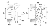
- FIG. 12 is a schematic view showing a waste gate valve device according to a fourth embodiment of the present invention
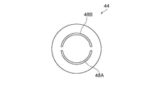
- FIG. 13 is a schematic view showing the waste gate valve shown in FIG.
- the waste gate valve device 41 according to the fourth embodiment of the present invention is the same as the waste gate valve device 11 according to the first embodiment of the present invention described above except for the protrusions 48A and 48B of the waste gate valve 44. Therefore, the same components as those of the waste gate valve device 11 according to the first embodiment of the present invention will be assigned the same reference numerals and descriptions thereof will be omitted.
- the pressure receiving portion (first protrusion 48A) and the suppressing portion (second protrusion 48B) of the waste gate valve 44 are provided. And.
- the pressure receiving portion is for receiving more pressure on the drive shaft side of the waste gate valve 44 when the waste gate valve 44 is opened.
- the pressure receiving portion according to the third embodiment of the present invention is constituted by a first projection 48A provided in a region near the surface facing the waste gate channel 12 in the waste gate valve 44. ing.
- the first protrusion 48A is provided so as to form a recess between itself and the suppressing portion (the second protrusion 48B), and as shown in FIG. 13, it is visually recognized as an arc when viewed from the waste gate channel side. Ru.
- the pressure receiving portion acts as a resistance of the exhaust gas flowing through the waste gate channel 12, whereby pressure acts on the drive shaft side of the waste gate 24.
- the suppressing portion is for suppressing a change in flow rate when the waste gate valve 44 is slightly opened.
- the suppression unit according to the fourth embodiment is configured by the second protrusion 48B provided on the side of the waste gate valve 44 facing the waste gate channel 12 away from the drive shaft 16 as shown in FIG. ing.
- the second protrusion 48 B is formed symmetrically to the first protrusion 48 A with respect to a horizontal line passing through the center of the waste gate valve 44. Therefore, as shown in FIG. 13, the second protrusion 48B is visually recognized in an arc shape when viewed from the waste gate channel side. Height of the second protrusion 48B is set to be less than half of the waste gate passage diameter D 1.
- the second projection 48B is the greater than half of the waste gate passage diameter D 1, the load acting on the lever 15 when opening the waste gate valve 44 becomes excessive. As shown in FIG. 13, the second projection 48B remains in the exhaust gas flowing through the waste gate channel 12 even when the waste gate valve 44 opens the waste gate channel 12, and the flow control at the time of slight opening Make it good.
- the waste gate valve device 41 according to the fourth embodiment of the present invention can exert more pressure on the drive shaft side of the waste gate valve 44 when the waste gate valve 44 is opened, and the waste gate valve 44 Flow controllability at the time of slight opening can be made favorable. Further, since the second protrusion 48 B is formed symmetrically with the first protrusion 48 A on the boundary of the horizontal line passing through the center of the waste gate valve 44, the waste gate valve 44 is considered without considering the upper and lower sides of the waste gate valve 44. Can be assembled to the lever 15.
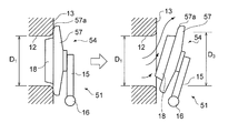
- FIG. 14 is a schematic view showing a waste gate valve device according to Embodiment 5 of the present invention.
- the waste gate valve device 51 according to the fifth embodiment of the present invention is the same as the waste gate valve device 11 according to the first embodiment of the present invention described above except for the valve body 57 of the waste gate valve 54. Therefore, the same components as those of the waste gate valve device 11 according to the first embodiment of the present invention will be assigned the same reference numerals and descriptions thereof will be omitted.
- the waste gate valve device 51 reduces the load acting on the waste gate valve 54, and the outer peripheral end 57a on the seating side of the valve body 57 has a curved surface. It is formed in shape. As a result, the exhaust gas having flowed through the waste gate channel 12 flows along the outer peripheral end 57 a on the seating side of the valve body 57, and the load acting on the waste gate valve 54 is reduced.
- the waste gate valve device 51 according to the fifth embodiment of the present invention can reduce the load acting on the waste gate valve 54. Thereby, the waste gate valve device 51 which is an embodiment of the present invention can make flow controllability good at the time of the waste gate valve 54 being slightly opened.
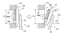
- FIG. 15 is a schematic view showing a waste gate valve device according to a sixth embodiment of the present invention
- FIG. 16 is a schematic view showing the waste gate valve shown in FIG.
- the waste gate valve device 61 according to the sixth embodiment of the present invention is the same as the waste gate valve device 11 according to the first embodiment of the present invention described above except for the projection 68 of the waste gate valve 64. Therefore, the same components as those of the waste gate valve device 11 according to the first embodiment of the present invention will be assigned the same reference numerals and descriptions thereof will be omitted.
- the waste gate valve device 61 according to the sixth embodiment of the present invention faces the waste gate flow passage 12 in the same manner as the waste gate valve device 11 according to the first embodiment of the present invention.
- a protrusion 68 is provided on the surface.
- a recess 68 a is further formed in the protrusion 68 according to the above-described embodiment of the present invention.
- the waste gate valve device 61 according to the sixth embodiment of the present invention can make the waste gate valve 64 lighter than the waste gate valve 14 according to the waste gate valve device 11 according to the first embodiment described above.
- the concave portion 68 a causes a partial flow, the flow control characteristic at the time of the slight opening of the waste gate valve 64 can be improved.
- FIG. 17 is a schematic view showing a waste gate valve device according to a seventh embodiment of the present invention.
- the waste gate valve device 71 according to the seventh embodiment of the present invention is the same as the waste gate valve device 11 according to the first embodiment of the present invention described above except for the projection 78 of the waste gate valve 74. Therefore, about the same composition as a waste gate valve which is Embodiment 1 of the present invention, the same numerals are attached and explanation is omitted.
- the waste gate valve device 71 according to the seventh embodiment of the present invention has a protrusion on the surface facing the waste gate channel 12 as in the waste gate valve device 11 according to the first embodiment of the present invention.
- 78 are provided.
- the protrusion 78 according to the seventh embodiment of the present invention has an enlarged portion 78a in which the base of the protrusion 18 according to the first embodiment of the present invention described above is expanded along the inner periphery of the enlarged portion.
- the waste gate valve device 71 according to the seventh embodiment of the present invention can avoid stress concentration at the boundary between the valve body 17 and the projection 78.
- FIG. 18 is a schematic view showing a waste gate valve device according to an eighth embodiment of the present invention.
- the waste gate valve device 81 according to the eighth embodiment of the present invention is a waste gate valve 84 (valve 87) in the waste gate valve device 11 according to the first embodiment of the present invention described above. Is rigidly fixed to the lever 85.
- the waste gate valve device 81 can prevent the waste gate valve 84 from chattering (fine very fast mechanical vibration) in a state where the leakage of exhaust gas is small.
- FIG. 19 is a schematic view showing a waste gate valve device according to a ninth embodiment of the present invention.
- the waste gate valve device 91 according to the ninth embodiment of the present invention aims to improve the sealing performance (sealing performance) of the waste gate valve 94.
- An elastically deformable portion is provided between the tip portion 97A for opening and closing the gate channel 12 and the base portion 97B attached to the lever 95.
- the elastically deformable portion according to the ninth embodiment is configured of a slit 97C.
- FIG. 20 is a schematic view showing a waste gate valve device according to a tenth embodiment of the present invention
- FIG. 21 is a schematic view showing a drive shaft and a bush for supporting the drive shaft.
- the waste gate valve device 101 is constituted by a turbine housing (not shown) provided with a waste gate flow path for bypassing the turbine, and a waste gate valve 104 for opening and closing the waste gate flow path. Ru.
- the waste gate valve 104 is fixed to one end of the drive shaft 106 via a lever 105, and the waste gate flow path is opened and closed by pivoting about an axis passing through the center of the drive shaft 106.
- a lever pin 161 is provided at the other end of the drive shaft 106, and a rod 191 provided at the actuator 109 is connected.
- the drive shaft 106 is pivoted via the rod 191 and the lever pin 161, and the waste gate valve 104 opens and closes the waste gate flow path.
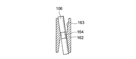
- a tapered surface 163 is provided so that the drive shaft 106 does not contact with the bush 162 for supporting the drive shaft 106.
- the inner periphery is narrowed at the center in the vertical direction so that the drive shaft 106 is in contact with the tapered surface 163 even when the drive shaft 106 is inclined, and the inner periphery is upper and lower in the vertical direction It is formed to be wide.
- the step portion 164 which is narrowed at the center in the vertical direction of the drive shaft 106 is provided to prevent the drive shaft 106 from being scraped by the narrow inner periphery.
- the waste gate valve device 101 can eliminate the situation where the drive shaft 106 partially contacts the bush 162 supporting the drive shaft 106, and can prevent the generation of edge surface pressure. .
- FIG. 22 is a schematic view showing a waste gate valve device according to an eleventh embodiment of the present invention.
- the waste gate valve device 111 is configured by a turbine housing (not shown) provided with a waste gate valve flow passage for bypassing the turbine, and a waste gate valve 114 for opening and closing the waste gate flow passage. Be done.
- the waste gate valve 114 is fixed to one end of the drive shaft 116 via a lever 115, and the drive shaft 116 is supported by a bush 1162 provided on the turbine housing.
- the waste gate valve 114 opens and closes the waste gate flow path by pivoting about an axis passing through the center of the drive shaft 116.
- a lever pin 1161 is provided at the other end of the drive shaft 116, and a rod 1191 provided on the actuator 119 is connected.
- the lever pin 1161 and the actuator 119 are arranged such that the pressure direction of the exhaust gas acting on the waste gate valve 114 coincides with the actuation direction of the actuator 119.
- the lever pin 1161 and the actuator 119 are arranged such that the waste gate valve 114 closes the waste gate flow path when the actuator 119 pushes the rod 1191.
- the drive shaft 116 is in the bush. It can prevent tilting.
- the exhaust gas does not leak through the clearance provided between the drive shaft 116 and the bush 1162 to the outside of the turbine housing. Further, as a result, the contact area between the drive shaft 116 and the bush 1162 is increased, and the effect of reducing the wear of the drive shaft 116 can be exhibited.
- the waste gate valve device according to the present invention can improve flow control characteristics at the time of slight opening, a part of exhaust gas is diverted in a turbocharged engine and thus the turbine It is suitable for the waste gate valve device which adjusts the inflow of the exhaust gas to
Landscapes
- Engineering & Computer Science (AREA)
- Chemical & Material Sciences (AREA)
- Combustion & Propulsion (AREA)
- Mechanical Engineering (AREA)
- General Engineering & Computer Science (AREA)
- Sliding Valves (AREA)
- Supercharger (AREA)
- Lift Valve (AREA)
Abstract
Description


このようにすれば、ウェイストゲートバルブを開放した場合に受圧部がウェイストバルブを支持する軸に近い側の領域で排ガスの圧力を受け、抑制部が軸に遠い側の領域で排ガスの流れを抑制できる。
このようにすれば、軸に近い側の領域で受圧部が排ガスの圧力を受け、軸に遠い側で抑制部が排ガスの流れを抑制できる。
このようにすれば、排ガスの圧力を凹部で効率的に受けることができる。
このようにすれば、排ガスの圧力を凹部で効率的に受けることができる。
このようにすれば、突起と弁体との間に応力集中が生じることを回避できる。
このようにすれば、ウェイストゲート流路を流れた排ガスが弁体の外周端部をスムースに流れることになり、ウェイストゲートバルブに作用する荷重を低減できる。
このようにすれば、ウェイストゲートバルブがウェイストゲート流路の出口を閉塞した場合に、弁体の先端部が撓み、ウェイストゲートバルブのシール性を確保できる。
このようにすれば、駆動軸がブッシュに片当たりする状態を解消でき、エッジ面圧の発生を防ぐことができる。
このようにすれば、ウェイストゲートバルブに作用する排ガスの圧力方向とアクチュエータの作動方向とが一致する。これにより、駆動軸がブッシュ内で傾くことを防止できる。これにより、排ガスが駆動軸とブッシュとの間に設けられたクリアランスを通りタービンハウジングの外部に漏れるのを抑制できる。



A1/A2≦0.2→D1≦0.447D2
A3/A2≦0.22→D3≦0.469D2
D3-D1≧(0.469―0.447)D2
D3-D1≧0.022×D2
D3-D1≧0.022×D1/0.447
D3―D1≧0.049D1
これにより、D1に対する拡開部2Aの出口径D3の関係性(拡大幅)は、下記の数式6により表される。


図5は、本発明の実施の形態1に係るウェイストゲートバルブ装置を示す模式図である。また、図6は、図5に示したウェイストゲートバルブ装置におけるウェイストゲートバルブの開度とウェイストゲート流路を流れる排ガスの質量流量との関係を示す図であり、図7は、図5に示したウェイストゲートバルブ装置におけるウェイストゲートバルブの開度とウェイストゲートバルブを支承する軸に作用する荷重との関係を示す図である。
図8は、本発明の実施の形態2に係るウェイストゲートバルブ装置を示す模式図であり、図9は、図8に示したウェイストゲートバルブを示す模式図である。本発明の実施の形態2であるウェイストゲートバルブ装置は、上述した本発明の実施の形態1であるウェイストゲートバルブ装置11とウェイストゲートバルブ24の突起28A,28Bを除いて異なるところはない。したがって、本発明の実施の形態1であるウェイストゲートバルブ装置11と同一の構成については同一の符号を付して説明を省略する。
図10は、本発明の実施の形態3に係るウェイストゲートバルブ装置を示す模式図であり、図11は、図10に示したウェイストゲートバルブを示す模式図である。本発明の実施の形態3であるウェイストゲートバルブ装置31は、上述した本発明の実施の形態1であるウェイストゲートバルブ装置11とウェイストゲートバルブ34の突起38を除いて異なるところはない。したがって、本発明の実施の形態1であるウェイストゲートバルブ装置11と同一の構成については同一の符号を付して説明を省略する。
図12は、本発明の実施の形態4に係るウェイストゲートバルブ装置を示す模式図であり、図13は、図12に示したウェイストゲートバルブを示す模式図である。本発明の実施の形態4であるウェイストゲートバルブ装置41は、上述した本発明の実施の形態1であるウェイストゲートバルブ装置11とウェイストゲートバルブ44の突起48A,48Bを除いて異なるところはない。したがって、本発明の実施の形態1であるウェイストゲートバルブ装置11と同一の構成については同一の符号を付して説明を省略する。
図14は、本発明の実施の形態5に係るウェイストゲートバルブ装置を示す模式図である。本発明の実施の形態5であるウェイストゲートバルブ装置51は、上述した本発明の実施の形態1であるウェイストゲートバルブ装置11とウェイストゲートバルブ54の弁体57を除いて異なるところはない。したがって、本発明の実施の形態1であるウェイストゲートバルブ装置11と同一の構成については同一の符号を付して説明を省略する。
図15は、本発明の実施の形態6であるウェイストゲートバルブ装置を示す模式図であり、図16は、図15に示したウェイストゲートバルブを示す模式図である。本発明の実施の形態6であるウェイストゲートバルブ装置61は、上述した本発明の実施の形態1であるウェイストゲートバルブ装置11とウェイストゲートバルブ64の突起68を除いて異なるところはない。したがって、本発明の実施の形態1であるウェイストゲートバルブ装置11と同一の構成については同一の符号を付して説明を省略する。
図17は、本発明の実施の形態7であるウェイストゲートバルブ装置を示す模式図である。本発明の実施の形態7であるウェイストゲートバルブ装置71は、上述した本発明の実施の形態1であるウェイストゲートバルブ装置11とウェイストゲートバルブ74の突起78を除いて異なるところはない。したがって、本発明の実施の形態1であるウェイストゲートバルブと同一の構成については同一の符号を付して説明を省略する。
図18は、本発明の実施の形態8であるウェイストゲートバルブ装置を示す模式図である。図18に示すように、本発明の実施の形態8であるウェイストゲートバルブ装置81は、上述した本発明の実施の形態1であるウェイストゲートバルブ装置11において、ウェイストゲートバルブ84(弁体87)はレバー85に剛に固定されている。
図19は、本発明の実施の形態9であるウェイストゲートバルブ装置を示す模式図である。図19に示すように、本発明の実施の形態9であるウェイストゲートバルブ装置91は、ウェイストゲートバルブ94のシール性(密閉性)の向上を目的としたもので、弁体97には、ウェイストゲート流路12を開閉する先端部97Aとレバー95に取り付けられる基部97Bとの間に弾性変形部を有する。本実施の形態9に係る弾性変形部は、スリット97Cで構成されている。これにより、弁体97の先端部97Aの剛性が低下され、ウェイストゲートバルブ94がウェイストゲート流路12を閉塞した場合に弁体17の先端部97Aが撓むことになる(弾性変形)。
図20は、本発明の実施の形態10であるウェイストゲートバルブ装置を示す模式図であり、図21は、駆動軸と駆動軸を支承するブッシュを示す模式図である。図20に示すように、ウェイストゲートバルブ装置101は、タービンをバイパスするウェイストゲート流路が設けられたタービンハウジング(図示せず)と、ウェイストゲート流路を開閉するウェイストゲートバルブ104とにより構成される。ウェイストゲートバルブ104は、レバー105を介して駆動軸106の一端に固定され、駆動軸106の中心を通る軸線を中心に旋回することによりウェイストゲート流路は開閉される。駆動軸106の他端にはレバーピン161が設けられ、アクチュエータ109に設けられたロッド191が連結されている。これによりアクチュエータ109を駆動すると、ロッド191及びレバーピン161を介して駆動軸106が旋回し、ウェイストゲートバルブ104はウェイストゲート流路を開閉する。
図22は、本発明の実施の形態11であるウェイストゲートバルブ装置を示す模式図である。図22に示すように、ウェイストゲートバルブ装置111は、タービンをバイパスするウェイストゲートバルブ流路が設けられたタービンハウジング(図示せず)と、ウェイストゲート流路を開閉するウェイストゲートバルブ114とにより構成される。ウェイストゲートバルブ114は、レバー115を介して駆動軸116の一端に固定され、駆動軸116は、タービンハウジングに設けられたブッシュ1162に支承される。これにより、ウェイストゲートバルブ114は、駆動軸116の中心を通る軸線を中心に旋回することにより、ウェイストゲート流路を開閉する。駆動軸116の他端にはレバーピン1161が設けられ、アクチュエータ119に設けられたロッド1191が連結されている。レバーピン1161とアクチュエータ119とは、ウェイストゲートバルブ114に作用する排ガスの圧力方向とアクチュエータ119の作動方向とが一致するように配置されている。具体的には、図22に示すように、レバーピン1161とアクチュエータ119とは、アクチュエータ119がロッド1191を押し出した時にウェイストゲートバルブ114がウェイストゲート流路を閉鎖するように配置される。
2 ウェイストゲート流路
2A 拡開部
3 タービンハウジング
4 ウェイストゲートバルブ
5 レバー
6 駆動軸
7 弁体
8 突起
D1 ウェイストゲート流路の径
D2 合流部の流路径
D3 ウェイストゲート流路の出口径
Pf 拡大面圧
11 ウェイストゲートバルブ装置
12 ウェイストゲート流路
12A 拡開部
13 タービンハウジング
14 ウェイストゲートバルブ
15 レバー
16 駆動軸
17 弁体
18 突起
21 ウェイストゲートバルブ装置
24 ウェイストゲートバルブ
28A 第1の突起
28B 第2の突起
31 ウェイストゲートバルブ装置
34 ウェイストゲートバルブ
38 突起
41 ウェイストゲートバルブ装置
44 ウェイストゲートバルブ
48A 第1の突起(受圧部)
48B 第2の突起(抑制部)
51 ウェイストゲートバルブ装置
54 ウェイストゲートバルブ
57 弁体
57a 外周
61 ウェイストゲートバルブ装置
64 ウェイストゲートバルブ
68 突起
68a 凹部
71 ウェイストゲートバルブ装置
74 ウェイストゲートバルブ
78 突起
78a 拡大部
81 ウェイストゲートバルブ装置
84 ウェイストゲートバルブ
85 レバー
87 弁体
91 ウェイストゲートバルブ装置
94 ウェイストゲートバルブ
95 レバー
97 弁体
97A 先端部
97B 基部
97C スリット
101 ウェイストゲートバルブ装置
104 ウェイストゲートバルブ
105 レバー
106 駆動軸
161 レバーピン
162 ブッシュ
163 テーパ面
164 段部
109 アクチュエータ
191 ロッド
111 ウェイストゲートバルブ装置
114 ウェイストゲートバルブ
115 レバー
116 駆動軸
1161 レバーピン
1162 ブッシュ
119 アクチュエータ
1191 ロッド
Claims (12)
- 排ガスがタービンをバイパスするウェイストゲート流路が設けられたタービンハウジングと、
前記ウェイストゲート流路の出口を開閉するウェイストゲートバルブと、
により構成され、
前記ウェイストゲートバルブは、
前記ウェイストゲート流路の出口を開閉する弁体と、
前記弁体が前記ウェイストゲート流路の出口を閉塞した場合に前記ウェイストゲート流路に収容される突起と、
を有するウェイストゲートバルブ装置であって、
前記ウェイストゲート流路は、前記ウェイストゲートバルブの全開時における排ガスの最大流量を確保しつつ、
前記タービンを経由した排ガスが合流する合流部に対する前記ウェイストゲート流路の流路断面積比を0.2以下とし、
さらに、前記ウェイストゲート流路の出口に流路断面積が拡大する拡開部を設けたことを特徴とするウェイストゲートバルブ装置。 - 前記ウェイストゲート流路の流路径D1は、前記合流部の流路径D2との関係において下記の数式1を満たすことを特徴とする請求項1に記載のウェイストゲートバルブ装置。

- 前記拡開部の出口径D3は、前記ウェイストゲート流路の流路径D1との関係において下記の数式2を満たすことを特徴とする請求項1又は2に記載のウェイストゲートバルブ装置

- 前記突起は、
前記ウェイストゲートバルブを開放した場合に前記ウェイストゲートバルブを支持する軸に近い側の領域で前記ウェイストゲート流路を流れる排ガスの圧力を受ける受圧部と、
前記軸に遠い側の領域で前記ウェイストゲート流路を流れる排ガスの流れを抑制する抑制部と、
を有すること特徴とする請求項1に記載のウェイストゲートバルブ装置。 - 前記受圧部は、前記軸に近い側の領域に形成され、
前記抑制部は、前記軸に遠い側の領域に形成されたことを特徴とする請求項4に記載のウェイストゲートバルブ装置。 - 前記受圧部は、前記抑制部との間に凹部を形成する円弧状に形成されたことを特徴とする請求項5に記載のウェイストゲートバルブ装置。
- 前記突起は、
前記ウェイストゲート流路を流れる排ガスを受け入れる凹部を有することを特徴とする請求項1に記載のウェイストゲートバルブ装置。 - 前記突起の基部は、前記拡開部の内周に沿って拡大する拡大部を有することを特徴とする請求項1に記載のウェイストゲートバルブ装置。
- 前記弁体の着座する側の外周端部は、曲面形状であることを特徴とする請求項1に記載のウェイストゲートバルブ装置。
- 前記弁体は、
前記ウェイストゲート流路を開閉する先端部と基部との間に前記先端部を撓ませる弾性変形部を有することを特徴とする請求項1に記載のウェイストゲートバルブ装置。 - 前記ウェイストゲートバルブが固定された駆動軸と、
前記駆動軸を支承するブッシュと、
を備え、
前記ブッシュの内周面にテーパ面を形成したことを特徴とする請求項1に記載のウェイストゲートバルブ装置。 - 一端に前記ウェイストゲートバルブが固定された駆動軸と、
前記駆動軸を支承するブッシュと、
前記駆動軸の他端に設けられたレバーピンと、
前記レバーピンに連結されたロッドが設けられたアクチュエータと、
を備え、
前記ウェイストゲートバルブに作用する圧力方向と前記アクチュエータの作動方向とが一致するように、前記レバーピンと前記アクチュエータとを配置したことを特徴とする請求項1に記載のウェイストゲートバルブ装置。
Priority Applications (5)
| Application Number | Priority Date | Filing Date | Title |
|---|---|---|---|
| PCT/JP2013/084672 WO2015097786A1 (ja) | 2013-12-25 | 2013-12-25 | ウェイストゲートバルブ装置 |
| CN201380080866.1A CN105723066B (zh) | 2013-12-25 | 2013-12-25 | 排气旁通阀装置 |
| US15/039,968 US10072564B2 (en) | 2013-12-25 | 2013-12-25 | Waste-gate valve device |
| EP13900040.0A EP3088697B1 (en) | 2013-12-25 | 2013-12-25 | Waste gate valve device |
| JP2015554363A JP6167186B2 (ja) | 2013-12-25 | 2013-12-25 | ウェイストゲートバルブ装置 |
Applications Claiming Priority (1)
| Application Number | Priority Date | Filing Date | Title |
|---|---|---|---|
| PCT/JP2013/084672 WO2015097786A1 (ja) | 2013-12-25 | 2013-12-25 | ウェイストゲートバルブ装置 |
Publications (1)
| Publication Number | Publication Date |
|---|---|
| WO2015097786A1 true WO2015097786A1 (ja) | 2015-07-02 |
Family
ID=53477726
Family Applications (1)
| Application Number | Title | Priority Date | Filing Date |
|---|---|---|---|
| PCT/JP2013/084672 Ceased WO2015097786A1 (ja) | 2013-12-25 | 2013-12-25 | ウェイストゲートバルブ装置 |
Country Status (5)
| Country | Link |
|---|---|
| US (1) | US10072564B2 (ja) |
| EP (1) | EP3088697B1 (ja) |
| JP (1) | JP6167186B2 (ja) |
| CN (1) | CN105723066B (ja) |
| WO (1) | WO2015097786A1 (ja) |
Cited By (4)
| Publication number | Priority date | Publication date | Assignee | Title |
|---|---|---|---|---|
| WO2018029027A1 (de) * | 2016-08-10 | 2018-02-15 | Continental Automotive Gmbh | Bypass-ventil mit klappenschürze für einen abgasturbolader und abgasturbolader mit einem solchen bypass-ventil |
| JP2022080560A (ja) * | 2020-11-18 | 2022-05-30 | トヨタ自動車株式会社 | ターボチャージャ |
| DE112021007512T5 (de) | 2021-09-08 | 2024-02-29 | Mitsubishi Heavy Industries Engine & Turbocharger, Ltd. | Schallqualitäts-bewertungsverfahren und schallqualitäts-bewertungsvorrichtung für wastegate-ventil |
| US11982222B2 (en) | 2020-08-17 | 2024-05-14 | Mitsubishi Heavy Industries Engine & Turbocharger, Ltd. | Wastegate valve device, turbine, and turbocharger |
Families Citing this family (6)
| Publication number | Priority date | Publication date | Assignee | Title |
|---|---|---|---|---|
| DE102015212381B4 (de) * | 2015-07-02 | 2017-10-12 | Continental Automotive Gmbh | Abgasturbolader mit einer Wastegate-Einrichtung |
| JP6834882B2 (ja) * | 2017-09-22 | 2021-02-24 | トヨタ自動車株式会社 | ターボチャージャ |
| CN108591494B (zh) * | 2018-04-10 | 2020-04-10 | 中国北方发动机研究所(天津) | 一种多截面混合调节阀阀芯设计方法 |
| DE102018220965A1 (de) * | 2018-12-04 | 2020-06-04 | Borgwarner Inc. | Klappenanordnung für eine Turbine eines Abgasturboladers |
| US10533491B1 (en) | 2019-03-25 | 2020-01-14 | Borgwarner Inc. | Connecting assembly and turbocharger including the connecting assembly |
| CN113123857B (zh) * | 2019-12-30 | 2022-08-09 | 上海汽车集团股份有限公司 | 一种涡轮箱废气旁通装置 |
Citations (10)
| Publication number | Priority date | Publication date | Assignee | Title |
|---|---|---|---|---|
| JPS582334U (ja) * | 1981-06-30 | 1983-01-08 | いすゞ自動車株式会社 | 過給内燃機関の排気バイパス弁装置 |
| JPS6078941U (ja) | 1983-11-04 | 1985-06-01 | 日産自動車株式会社 | タ−ボチヤ−ジヤの排気バイパス弁 |
| JPH02131032U (ja) * | 1989-04-05 | 1990-10-30 | ||
| JPH0495626U (ja) | 1991-01-14 | 1992-08-19 | ||
| JPH0643227U (ja) * | 1992-06-01 | 1994-06-07 | 愛三工業株式会社 | ターボチャージャ用ウェイストゲートバルブ |
| JP2009092026A (ja) * | 2007-10-11 | 2009-04-30 | Mitsubishi Heavy Ind Ltd | 流体切換弁装置とこれを備えた排気ガス制御バルブ及びウェストゲートバルブ |
| JP2009203835A (ja) | 2008-02-26 | 2009-09-10 | Mitsubishi Heavy Ind Ltd | ターボチャージャの排気バイパス弁 |
| JP2011179401A (ja) * | 2010-03-01 | 2011-09-15 | Mitsubishi Heavy Ind Ltd | ウエストゲートバルブ装置 |
| JP2012504727A (ja) * | 2008-10-01 | 2012-02-23 | ボーグワーナー インコーポレーテッド | 可変流ウェイストゲート |
| WO2013128720A1 (ja) * | 2012-02-28 | 2013-09-06 | 三菱重工業株式会社 | 弁 |
Family Cites Families (10)
| Publication number | Priority date | Publication date | Assignee | Title |
|---|---|---|---|---|
| JPS5697532U (ja) * | 1979-12-27 | 1981-08-01 | ||
| JPS56171631U (ja) * | 1980-05-23 | 1981-12-18 | ||
| JPS62156139U (ja) | 1986-03-25 | 1987-10-03 | ||
| JPS63177319U (ja) | 1987-04-22 | 1988-11-17 | ||
| US7788922B2 (en) | 2007-10-04 | 2010-09-07 | Delphi Technologies, Inc. | System and method for model based boost control of turbo-charged engines |
| JP5256977B2 (ja) | 2008-10-03 | 2013-08-07 | 株式会社Ihi | ターボチャージャ |
| DE102011011003A1 (de) * | 2011-02-11 | 2012-08-16 | Ihi Charging Systems International Gmbh | Ventileinrichtung für ein Abblaseventil eines Abgasturboladers |
| DE102011076587A1 (de) * | 2011-05-27 | 2012-11-29 | Continental Automotive Gmbh | Abgasturbolader mit einem Kugelhahn-Wastegate-Ventil mit spannungsentlastetem Kurbelarm |
| DE102011108205A1 (de) * | 2011-07-20 | 2013-01-24 | Daimler Ag | Ventilelement für einen Abgasturbolader sowie Turbine für einen Abgasturbolader mit einem solchen Ventilelement |
| EP2798172B1 (en) * | 2011-12-27 | 2015-10-14 | Mitsubishi Heavy Industries, Ltd. | Wastegate valve and exhaust gas turbocharger equipped with wastegate valve |
-
2013
- 2013-12-25 EP EP13900040.0A patent/EP3088697B1/en active Active
- 2013-12-25 WO PCT/JP2013/084672 patent/WO2015097786A1/ja not_active Ceased
- 2013-12-25 CN CN201380080866.1A patent/CN105723066B/zh active Active
- 2013-12-25 JP JP2015554363A patent/JP6167186B2/ja active Active
- 2013-12-25 US US15/039,968 patent/US10072564B2/en active Active
Patent Citations (10)
| Publication number | Priority date | Publication date | Assignee | Title |
|---|---|---|---|---|
| JPS582334U (ja) * | 1981-06-30 | 1983-01-08 | いすゞ自動車株式会社 | 過給内燃機関の排気バイパス弁装置 |
| JPS6078941U (ja) | 1983-11-04 | 1985-06-01 | 日産自動車株式会社 | タ−ボチヤ−ジヤの排気バイパス弁 |
| JPH02131032U (ja) * | 1989-04-05 | 1990-10-30 | ||
| JPH0495626U (ja) | 1991-01-14 | 1992-08-19 | ||
| JPH0643227U (ja) * | 1992-06-01 | 1994-06-07 | 愛三工業株式会社 | ターボチャージャ用ウェイストゲートバルブ |
| JP2009092026A (ja) * | 2007-10-11 | 2009-04-30 | Mitsubishi Heavy Ind Ltd | 流体切換弁装置とこれを備えた排気ガス制御バルブ及びウェストゲートバルブ |
| JP2009203835A (ja) | 2008-02-26 | 2009-09-10 | Mitsubishi Heavy Ind Ltd | ターボチャージャの排気バイパス弁 |
| JP2012504727A (ja) * | 2008-10-01 | 2012-02-23 | ボーグワーナー インコーポレーテッド | 可変流ウェイストゲート |
| JP2011179401A (ja) * | 2010-03-01 | 2011-09-15 | Mitsubishi Heavy Ind Ltd | ウエストゲートバルブ装置 |
| WO2013128720A1 (ja) * | 2012-02-28 | 2013-09-06 | 三菱重工業株式会社 | 弁 |
Non-Patent Citations (2)
| Title |
|---|
| "Research Report of the R&D Sectional Committee on High-speed Flow of Gas in a Tube", 1978, THE JAPAN SOCIETY OF MECHANICAL ENGINEERS |
| See also references of EP3088697A4 * |
Cited By (7)
| Publication number | Priority date | Publication date | Assignee | Title |
|---|---|---|---|---|
| WO2018029027A1 (de) * | 2016-08-10 | 2018-02-15 | Continental Automotive Gmbh | Bypass-ventil mit klappenschürze für einen abgasturbolader und abgasturbolader mit einem solchen bypass-ventil |
| US10746092B2 (en) | 2016-08-10 | 2020-08-18 | Cpt Group Gmbh | Bypass valve having a flap skirt for an exhaust-gas turbocharger, and exhaust-gas turbocharger having such a bypass valve |
| US11982222B2 (en) | 2020-08-17 | 2024-05-14 | Mitsubishi Heavy Industries Engine & Turbocharger, Ltd. | Wastegate valve device, turbine, and turbocharger |
| JP2022080560A (ja) * | 2020-11-18 | 2022-05-30 | トヨタ自動車株式会社 | ターボチャージャ |
| JP7396254B2 (ja) | 2020-11-18 | 2023-12-12 | トヨタ自動車株式会社 | ターボチャージャ |
| DE112021007512T5 (de) | 2021-09-08 | 2024-02-29 | Mitsubishi Heavy Industries Engine & Turbocharger, Ltd. | Schallqualitäts-bewertungsverfahren und schallqualitäts-bewertungsvorrichtung für wastegate-ventil |
| DE112021007512B4 (de) * | 2021-09-08 | 2025-09-11 | Mitsubishi Heavy Industries Engine & Turbocharger, Ltd. | Schallqualitäts-bewertungsverfahren und schallqualitäts-bewertungsvorrichtung für wastegate-ventil |
Also Published As
| Publication number | Publication date |
|---|---|
| US20170030261A1 (en) | 2017-02-02 |
| US10072564B2 (en) | 2018-09-11 |
| JP6167186B2 (ja) | 2017-07-19 |
| EP3088697A1 (en) | 2016-11-02 |
| JPWO2015097786A1 (ja) | 2017-03-23 |
| EP3088697B1 (en) | 2018-08-22 |
| CN105723066B (zh) | 2018-07-31 |
| CN105723066A (zh) | 2016-06-29 |
| EP3088697A4 (en) | 2016-12-21 |
Similar Documents
| Publication | Publication Date | Title |
|---|---|---|
| WO2015097786A1 (ja) | ウェイストゲートバルブ装置 | |
| JP5988853B2 (ja) | 排気還流バルブ | |
| US20120326069A1 (en) | Step type valve | |
| KR101643517B1 (ko) | 증기 밸브 | |
| KR20080099635A (ko) | 이중밀봉구조를 갖는 글로브밸브 | |
| CN104136821B (zh) | 阀门 | |
| JP3560102B2 (ja) | 逆止弁付ピストン | |
| CN104169623B (zh) | 流体循环阀 | |
| JP5767124B2 (ja) | 制御弁 | |
| CN102032351B (zh) | 具有聚分流道的提升阀和减小总压力损失的方法 | |
| CN111765258A (zh) | 一种电动阀 | |
| JP5185725B2 (ja) | 蒸気タービン用蒸気弁 | |
| US20110297867A1 (en) | Flow guided valve seat for steam turbine valves | |
| KR20080084328A (ko) | 이중밀봉구조를 갖는 글로브밸브 | |
| CN206309473U (zh) | 一种废气门的阀瓣组合结构 | |
| JP5535768B2 (ja) | 蒸気弁 | |
| WO2021100408A1 (ja) | Egrバルブ装置 | |
| WO2020200265A1 (zh) | 一种电动阀 | |
| JP2015206323A (ja) | バルブ装置 | |
| KR100489112B1 (ko) | 직경 가변형 배기 시스템 | |
| JP2007138745A (ja) | 内燃機関の吸気装置 | |
| JP6207994B2 (ja) | ポペット弁およびバルブアセンブリ | |
| JP4899130B2 (ja) | バタフライ弁 | |
| JP2006009843A (ja) | バルブ装置及び排気ガス浄化装置 | |
| WO2020200266A1 (zh) | 一种电动阀 |
Legal Events
| Date | Code | Title | Description |
|---|---|---|---|
| 121 | Ep: the epo has been informed by wipo that ep was designated in this application |
Ref document number: 13900040 Country of ref document: EP Kind code of ref document: A1 |
|
| ENP | Entry into the national phase |
Ref document number: 2015554363 Country of ref document: JP Kind code of ref document: A |
|
| REEP | Request for entry into the european phase |
Ref document number: 2013900040 Country of ref document: EP |
|
| WWE | Wipo information: entry into national phase |
Ref document number: 2013900040 Country of ref document: EP |
|
| WWE | Wipo information: entry into national phase |
Ref document number: 15039968 Country of ref document: US |
|
| NENP | Non-entry into the national phase |
Ref country code: DE |