WO2015099062A1 - Procédé de fabrication d'un module de câblage pour batterie - Google Patents
Procédé de fabrication d'un module de câblage pour batterie Download PDFInfo
- Publication number
- WO2015099062A1 WO2015099062A1 PCT/JP2014/084354 JP2014084354W WO2015099062A1 WO 2015099062 A1 WO2015099062 A1 WO 2015099062A1 JP 2014084354 W JP2014084354 W JP 2014084354W WO 2015099062 A1 WO2015099062 A1 WO 2015099062A1
- Authority
- WO
- WIPO (PCT)
- Prior art keywords
- bus bar
- battery
- insulating resin
- wiring module
- battery wiring
- Prior art date
- Legal status (The legal status is an assumption and is not a legal conclusion. Google has not performed a legal analysis and makes no representation as to the accuracy of the status listed.)
- Ceased
Links
Images










Classifications
-
- H—ELECTRICITY
- H01—ELECTRIC ELEMENTS
- H01M—PROCESSES OR MEANS, e.g. BATTERIES, FOR THE DIRECT CONVERSION OF CHEMICAL ENERGY INTO ELECTRICAL ENERGY
- H01M50/00—Constructional details or processes of manufacture of the non-active parts of electrochemical cells other than fuel cells, e.g. hybrid cells
- H01M50/20—Mountings; Secondary casings or frames; Racks, modules or packs; Suspension devices; Shock absorbers; Transport or carrying devices; Holders
- H01M50/289—Mountings; Secondary casings or frames; Racks, modules or packs; Suspension devices; Shock absorbers; Transport or carrying devices; Holders characterised by spacing elements or positioning means within frames, racks or packs
- H01M50/293—Mountings; Secondary casings or frames; Racks, modules or packs; Suspension devices; Shock absorbers; Transport or carrying devices; Holders characterised by spacing elements or positioning means within frames, racks or packs characterised by the material
-
- H—ELECTRICITY
- H01—ELECTRIC ELEMENTS
- H01M—PROCESSES OR MEANS, e.g. BATTERIES, FOR THE DIRECT CONVERSION OF CHEMICAL ENERGY INTO ELECTRICAL ENERGY
- H01M50/00—Constructional details or processes of manufacture of the non-active parts of electrochemical cells other than fuel cells, e.g. hybrid cells
- H01M50/50—Current conducting connections for cells or batteries
- H01M50/502—Interconnectors for connecting terminals of adjacent batteries; Interconnectors for connecting cells outside a battery casing
- H01M50/505—Interconnectors for connecting terminals of adjacent batteries; Interconnectors for connecting cells outside a battery casing comprising a single busbar
-
- H—ELECTRICITY
- H01—ELECTRIC ELEMENTS
- H01M—PROCESSES OR MEANS, e.g. BATTERIES, FOR THE DIRECT CONVERSION OF CHEMICAL ENERGY INTO ELECTRICAL ENERGY
- H01M50/00—Constructional details or processes of manufacture of the non-active parts of electrochemical cells other than fuel cells, e.g. hybrid cells
- H01M50/50—Current conducting connections for cells or batteries
- H01M50/502—Interconnectors for connecting terminals of adjacent batteries; Interconnectors for connecting cells outside a battery casing
- H01M50/509—Interconnectors for connecting terminals of adjacent batteries; Interconnectors for connecting cells outside a battery casing characterised by the type of connection, e.g. mixed connections
- H01M50/51—Connection only in series
-
- H—ELECTRICITY
- H01—ELECTRIC ELEMENTS
- H01M—PROCESSES OR MEANS, e.g. BATTERIES, FOR THE DIRECT CONVERSION OF CHEMICAL ENERGY INTO ELECTRICAL ENERGY
- H01M50/00—Constructional details or processes of manufacture of the non-active parts of electrochemical cells other than fuel cells, e.g. hybrid cells
- H01M50/20—Mountings; Secondary casings or frames; Racks, modules or packs; Suspension devices; Shock absorbers; Transport or carrying devices; Holders
- H01M50/204—Racks, modules or packs for multiple batteries or multiple cells
- H01M50/207—Racks, modules or packs for multiple batteries or multiple cells characterised by their shape
- H01M50/209—Racks, modules or packs for multiple batteries or multiple cells characterised by their shape adapted for prismatic or rectangular cells
-
- H—ELECTRICITY
- H01—ELECTRIC ELEMENTS
- H01M—PROCESSES OR MEANS, e.g. BATTERIES, FOR THE DIRECT CONVERSION OF CHEMICAL ENERGY INTO ELECTRICAL ENERGY
- H01M50/00—Constructional details or processes of manufacture of the non-active parts of electrochemical cells other than fuel cells, e.g. hybrid cells
- H01M50/50—Current conducting connections for cells or batteries
- H01M50/543—Terminals
- H01M50/547—Terminals characterised by the disposition of the terminals on the cells
- H01M50/55—Terminals characterised by the disposition of the terminals on the cells on the same side of the cell
-
- H—ELECTRICITY
- H01—ELECTRIC ELEMENTS
- H01M—PROCESSES OR MEANS, e.g. BATTERIES, FOR THE DIRECT CONVERSION OF CHEMICAL ENERGY INTO ELECTRICAL ENERGY
- H01M50/00—Constructional details or processes of manufacture of the non-active parts of electrochemical cells other than fuel cells, e.g. hybrid cells
- H01M50/50—Current conducting connections for cells or batteries
- H01M50/543—Terminals
- H01M50/552—Terminals characterised by their shape
- H01M50/553—Terminals adapted for prismatic, pouch or rectangular cells
-
- Y—GENERAL TAGGING OF NEW TECHNOLOGICAL DEVELOPMENTS; GENERAL TAGGING OF CROSS-SECTIONAL TECHNOLOGIES SPANNING OVER SEVERAL SECTIONS OF THE IPC; TECHNICAL SUBJECTS COVERED BY FORMER USPC CROSS-REFERENCE ART COLLECTIONS [XRACs] AND DIGESTS
- Y02—TECHNOLOGIES OR APPLICATIONS FOR MITIGATION OR ADAPTATION AGAINST CLIMATE CHANGE
- Y02E—REDUCTION OF GREENHOUSE GAS [GHG] EMISSIONS, RELATED TO ENERGY GENERATION, TRANSMISSION OR DISTRIBUTION
- Y02E60/00—Enabling technologies; Technologies with a potential or indirect contribution to GHG emissions mitigation
- Y02E60/10—Energy storage using batteries
Definitions
- the present invention relates to a method for manufacturing a battery wiring module.
- Vehicles such as hybrid cars and electric cars are equipped with an in-vehicle battery pack connected to a power converter for driving a motor.
- the battery pack is provided with a battery module including a large number of battery cells.
- each battery cell is overlapped so that any one of the electrode terminals in each battery cell is arranged in a row and the other electrode terminal is arranged in a row.
- electrode terminals of adjacent battery cells are connected by a connecting member such as a bus bar so that the plurality of battery cells are connected in series or in parallel. Some of the connection members are connected to electric wires.
- the above-mentioned electric wires (voltage detection lines) for detecting the voltage of the battery cell are connected to each other in order to stop charging and discharging before the voltage between the battery cells becomes abnormal. It is attached to the member (each bus bar).
- the plurality of voltage detection lines are routed on the battery module in a bundled state. For this reason, in such a bus bar module, when the number of voltage detection lines is large, the bundled voltage detection lines may become thick and difficult to bend or become heavy, making wiring work difficult. There is sex.
- the tip of the voltage detection wire coating is peeled off, a round terminal is crimped to the exposed core wire, the round terminal is fitted to the electrode terminal of the battery cell, and the electrode A structure is adopted in which a round terminal is fastened together with a connecting member to a male screw portion of the terminal together with a nut. For this reason, in this bus bar module, the resistance of the contact surface between the connection member and the round terminal is increased, which may cause a voltage drop.
- a high voltage detection module device (bus bar module) that can be easily wired to each battery cell with a simple structure and can suppress the occurrence of a voltage drop has been proposed.
- a high voltage detection module device (bus bar module) that can be easily wired to each battery cell with a simple structure and can suppress the occurrence of a voltage drop has been proposed.
- a plurality of bus bars are arranged on an insulating frame combined with the battery pack body so that predetermined + terminals and ⁇ terminals of the battery cells can be connected.
- a flat cable is disposed in a region of the insulating frame other than the region, and a conductor wire cut into a predetermined shape between the conductor wires of the flat cable and cut off leaving the root is welded to a predetermined bus bar.
- This high voltage detection module device is configured by an insulating frame, a plurality of bus bars, and a flat cable to simplify the structure.
- the high voltage detection module device is formed by a bus bar arranging process on the insulating frame, a conductor cable cutting process of the flat cable, and a conductor cable welding process to the bus bar. We are trying to simplify the work.
- the insulating frame in the high-voltage detection module device of Patent Document 1 has a plurality of protrusions at a predetermined interval on the lower surface of a plate-like portion having a rectangular planar shape, and a plurality of protrusions at a predetermined interval on the plate-like portion.
- the through hole is opened.
- the high voltage detection module device has a plurality of openings that are opened at a predetermined interval and the number of protrusions that are fitted into the gaps between the battery cells, and between the positive terminals and the negative terminals of the battery cells.
- the predetermined interval and the numerical aperture of the through holes must be changed according to the size of the battery cell, and the insulating frame becomes a dedicated component for each type of battery pack. Therefore, the high-voltage detection module device has no versatility, and it is difficult to reduce the manufacturing cost.
- the present invention has been made in view of the above circumstances, and provides a method for manufacturing a battery wiring module that can be easily wired to each battery cell with a simple structure and that is highly versatile and can reduce manufacturing costs.
- the purpose is to do.
- a method for manufacturing a battery wiring module includes a long side portion of a long flat conductor, a predetermined interval with respect to the long side portion, and the long side portion.
- a covering step of covering each outer peripheral portion of a plurality of linear conductors arranged in parallel at predetermined intervals along the side portion with an insulating resin portion; and the flat conductor in the longitudinal direction of the flat conductor Are electrode terminals provided in at least two battery cells connected in the same direction among a plurality of battery cells that are divided at predetermined intervals along the same direction, and the electrode terminals arranged in the same direction are connected to each other.
- the method includes a pressing step of forming a plurality of bus bars for electrical connection and a connection step of electrically connecting the plurality of linear conductors to the predetermined bus bar.
- the connecting step it is preferable that the plurality of linear conductors at one end of the insulating resin portion are separated from each other and the linear conductors at the one end are electrically connected to the predetermined bus bar.
- a positive electrode bus bar electrically connected only to the positive electrode terminal and a negative electrode bus bar electrically connected only to the negative electrode terminal are formed, and the positive electrode bus bar and the negative electrode It is desirable to form cut and raised pieces on each bus bar, and to electrically connect the cut and raised pieces to the predetermined linear conductor covered with the insulating resin portion in the connecting step.
- connection conductor In the connecting step, one end of the connection conductor is press-contacted to the predetermined linear conductor covered with the insulating resin portion, and the other end of the connection conductor is electrically connected to the predetermined bus bar. It is desirable.
- the one long side portion of the flat conductor is covered with a first insulating resin portion as the insulating resin portion, and the other long side portion of the flat conductor is covered with a second insulating resin. It is desirable to cover by part.
- the method for manufacturing a battery wiring module according to the present invention can be easily wired to each battery cell with a simple structure, and has high versatility and can reduce manufacturing costs.
- FIG. 1 is an overall perspective view of a battery pack in which a battery wiring module according to a first embodiment of the present invention is combined.
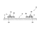
- FIG. 2 is a plan view of the battery pack shown in FIG. 3A is a cross-sectional view of the main part of the battery pack taken along line AA in FIG. 3B is a cross-sectional view of the battery wiring module taken along line BB of FIG.
- FIG. 4 is a partial perspective view of the battery wiring module shown in FIG.
- FIG. 5A is a plan view and a cross-sectional view of relevant parts for explaining an arrangement process of the battery wiring module shown in FIG.
- FIG. 5B is a plan view and a cross-sectional view of relevant parts for explaining a covering process of the battery wiring module shown in FIG.
- FIG. 5A is a plan view and a cross-sectional view of relevant parts for explaining an arrangement process of the battery wiring module shown in FIG.
- FIG. 5B is a plan view and a cross-sectional view of relevant parts for explaining
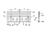
- FIG. 5C is a plan view and a cross-sectional view of relevant parts for explaining a pressing step of the battery wiring module shown in FIG.
- FIG. 5D is a plan view and a cross-sectional view of relevant parts for explaining a connection process of the battery wiring module shown in FIG. 1.
- FIG. 6 is a partial plan view of the battery wiring module.
- FIG. 7A is an exploded perspective view of main parts of the battery pack shown in FIG.
- FIG. 7B is an enlarged view of a Y portion in FIG. 7A.
- FIG. 8A is a plan view of the battery wiring module before the connection step according to the second embodiment of the present invention.
- FIG. 8B is a plan view of the battery wiring module that has undergone the connection step according to the second embodiment of the present invention.
- FIG. 9A is a plan view of the battery wiring module before the connection step according to the third embodiment of the present invention.
- FIG. 9B is a plan view of the battery wiring module that has undergone the connection step according to the third embodiment of the present invention.
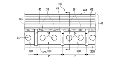
- FIG. 10A is a plan view of relevant parts for explaining a battery wiring module arranging step according to the fourth embodiment of the present invention.
- FIG. 10B is a plan view of relevant parts for explaining a covering step of the battery wiring module according to the fourth embodiment of the present invention.
- FIG. 10C is a plan view of relevant parts for explaining the pressing step of the battery wiring module according to the fourth embodiment of the present invention.
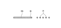
- FIG. 11A is a cross-sectional view illustrating the arrangement process shown in FIG. 10A.
- FIG. 11B is a cross-sectional view illustrating the covering step shown in FIG. 10B.
- FIG. 11C is a cross-sectional view illustrating the pressing step shown in FIG. 10C.
- the battery wiring module is provided in the battery pack, and is attached to the battery module including a plurality of battery cells.
- the battery pack is, for example, mounted on a vehicle such as an electric vehicle or a hybrid vehicle, and exchanges (charges) electric power with a rotating machine (electric motor, generator, motor generator) as a drive source of the vehicle via an inverter. Discharge).
- the battery module is obtained by superimposing battery cells in the same direction so that any one of the electrode terminals in each battery cell is arranged in a row and the other electrode terminal is arranged in a row. .
- any one of the electrode terminals of the plurality of battery cells is connected by a connection member (first connection member) such as a bus bar so that the plurality of battery cells are connected in series or in parallel.
- the first connecting member is an electrode terminal provided in at least two battery cells connected in the same direction among the plurality of battery cells stacked in the same direction, and the electrode terminals arranged in the same direction are electrically connected to each other. To connect to.
- connecting members such as bus bars are connected to the positive terminal and the negative terminal arranged at both ends of the battery module.
- linear conductors are connected to the first connection member and the second connection member, respectively.
- the first and second connecting members and the respective linear conductors can be used, for example, for confirming the battery state, or for power transmission during charging / discharging.
- the battery wiring module of the present embodiment is a module obtained by modularizing such connection members (first and second connection members) and a linear conductor. One battery wiring module is arranged for each row of electrode terminals. As shown in FIGS.
- the battery pack 10 of this embodiment includes a battery module 20 including a plurality of battery cells 12 and battery wiring modules 30 ⁇ / b> A and 30 ⁇ / b> B.
- the battery module 20 has a plurality of battery cells 12 arranged and fixed via a separator in a box-shaped housing (not shown).
- the battery wiring modules 30 ⁇ / b> A and 30 ⁇ / b> B of the present embodiment are exemplified as those for measuring the voltage (that is, the battery state) of the battery cell 12.
- the battery wiring modules 30A and 30B include a plurality of bus bars 32 for connecting a plurality of battery cells 12 in series, a voltage detection line 40 for measuring the voltage of each battery cell 12, and a voltage detection line 40. And a connector 50 that is connected and fixed to one end thereof.
- the bus bar 32 is prepared by being divided into a bus bar (first connecting member) 32A and a bus bar (second connecting member) 32B.
- the battery cell 12 is a secondary battery, and includes one positive terminal 13A and one negative terminal 13B as electrode terminals.
- this battery cell 12 what has a rectangular parallelepiped housing
- the positive terminal 13A and the negative terminal 13B are projected in the same direction.
- the positive electrode terminal 13A and the negative electrode terminal 13B are projected from a certain surface of the casing. Specifically, as shown in FIG.
- the battery cell 12 of the present embodiment has a positive electrode terminal 13 ⁇ / b> A and a negative electrode terminal 13 ⁇ / b> B projecting from an upper surface (for example, a surface facing upward of the vehicle when the vehicle is mounted).
- Each battery cell 12 is overlapped so as to be continuous in the same direction, thereby forming two rows of electrode terminals arranged in the same direction.
- the illustrated battery cells 12 are alternately stacked in opposite directions so that the positive electrode terminal 13A and the negative electrode terminal 13B are adjacent to each other in each column. That is, in each of the columns, the positive terminal 13A and the negative terminal 13B are alternately arranged.
- the separators 22 made of insulating resin shown in FIG. 7A are disposed on both sides of each battery cell 12 (both side surfaces in the overlapping direction of the battery cells 12).
- a partition portion 24 that protrudes upward from the upper surface of the battery cell 12 is formed at the upper end of the separator 22.
- the partition portion 24 is inserted into a partition insertion portion 45 such as a slit or a through hole formed between adjacent bus bars 32.
- the partition insertion part 45 is formed in an elongated rectangular shape in accordance with the shape of the plate-like partition part 24.
- the partition part 24 prevents the short circuit between the electrode terminals by a tool by making it protrude above the partition insertion part 45 (projection direction of an electrode terminal).
- partition insertion portion 45 is formed between adjacent bus bars 32A and between adjacent bus bars 32A and 32B.
- partition insertion portion 45 is formed between adjacent bus bars 32A.
- the partition insertion part 45 is also for separating adjacent bus bars 32 from each other.
- strip-shaped battery wiring modules 30 ⁇ / b> A and 30 ⁇ / b> B extending along the arrangement direction of the battery cells 12 (the overlapping direction of the battery cells 12) are disposed on the plurality of battery cells 12. ing.
- the battery wiring modules 30A and 30B are arranged one by one for each row of electrode terminals.
- the battery wiring module 30A includes a bus bar array including a plurality of bus bars 32A and two bus bars 32B, and a voltage detection line 40 having a linear conductor 21 electrically connected to each of the predetermined bus bars 32A and 32B. .
- the bus bars 32A are arranged side by side along the arrangement direction of the battery cells 12, and one bus bar 32B is arranged at both ends in the arrangement direction.
- the two bus bars 32B are respectively connected to one electrode terminal of the stacked battery cells 12 disposed at both ends.
- One bus bar 32B is a positive bus bar that is electrically connected only to the positive terminal 13A.
- the other bus bar 32B is a negative electrode bus bar that is electrically connected only to the negative electrode terminal 13B.
- the battery wiring module 30B includes a bus bar array including a plurality of bus bars 32A, and a voltage detection line 40 having linear conductors 21 that are electrically connected to the predetermined bus bars 32A.
- each linear conductor 21 has its axial direction along the direction in which the battery cells 12 are arranged (that is, along the bus bar row), and is provided in parallel with a predetermined interval therebetween. Deploy.
- the voltage detection line 40 is arranged at a predetermined interval from the bus bar row. That is, a predetermined interval is provided between the bus bar row side of each linear conductor 21 and the bus bar row.
- FIG. 4 is a diagram illustrating the battery wiring module 30B as an example.
- the terminal insertion hole 34 of the positive electrode terminal 13A is formed in one bus bar 32B
- the terminal insertion hole 34 of the negative electrode terminal 13B is formed in the other bus bar 32B.
- two bus bars 32B are arranged so as to sandwich the five bus bars 32A.
- six bus bars 32A are arranged.
- each bus bar 32A, 32B has a generally rectangular shape, and the corresponding electrode terminal is inserted into the terminal insertion hole 34.
- the bus bars 32A and 32B are punched into a long rectangular flat conductor 33 made of a metal plate material such as copper, copper alloy, aluminum, aluminum alloy, gold, and stainless steel (SUS) in a press process described later. Is formed.
- the bus bars 32A and 32B may be plated with Sn, Ni, Ag, Au, etc. in order to improve weldability.
- the bus bars 32 ⁇ / b> A and 32 ⁇ / b> B of the present embodiment are tightened by screwing nuts 15 into the positive terminal 13 ⁇ / b> A and the negative terminal 13 ⁇ / b> B inserted through the terminal insertion holes 34. Thereby, the bus bars 32A and 32B are electrically connected to the positive terminal 13A and the negative terminal 13B.
- the bus bar according to the present invention may be electrically connected by welding to the positive terminal and the negative terminal without forming the terminal insertion hole 34.
- the bus bars 32 ⁇ / b> A and 32 ⁇ / b> B may be reduced in weight by, for example, forming the corners in an arc shape corresponding to the circular terminal insertion hole 34.
- the voltage detection lines 40 constituting the battery wiring modules 30A and 30B include a plurality of linear conductors 21 arranged in parallel at predetermined intervals, and an outer peripheral portion of the plurality of linear conductors 21 arranged in such a manner. It forms in the shape of a flat cable which has the insulating resin part (1st insulating resin part 23A) coat
- the first insulating resin portion 23A is made of, for example, an insulating resin such as polypropylene (PP), polyvinyl chloride (PVC), polybutylene terephthalate (PBT), or polyethylene terephthalate (PET).
- an insulating resin is extruded together with a plurality of linear conductors 21 so as to cover the outer peripheral portions of the respective linear conductors 21 and integrated with the first insulating resin.
- Part 23A is formed.
- the linear conductor 21 a single conductor such as a flat conductor and a round conductor, and various conductors such as a stranded wire can be used.
- the linear conductor 21 is made of a copper alloy, an aluminum alloy, or the like.
- the bus bars 32 (32A, 32B) are arranged in parallel along at least one of the linear conductors 21 arranged at both ends of the voltage detection line 40.
- Each of the plurality of linear conductors 21 in the illustrated battery wiring modules 30A and 30B has a predetermined interval with respect to the side edge portion 32a of the bus bar 32 and a predetermined interval with each other along the side edge portion 32a. Are arranged in parallel.
- an insulating resin portion (second insulating resin portion 23B) is also provided on the side edge portion 32b opposite to the side edge portion 32a of the bus bar 32.
- the second insulating resin portion 23B functions as a connecting portion that connects the bus bars 32 in the battery wiring modules 30A and 30B, and extends along the direction in which the battery cells 12 are arranged, while being opposite to the side edge portion. Connect 32b together.
- the second insulating resin portion 23B is formed of the same insulating resin as the first insulating resin portion 23A. In this illustration, the second insulating resin portion 23B is extruded together with the first insulating resin portion 23A.
- the first insulating resin portion 23A and the second insulating resin portion 23B are flexible. Even if the insulating resin is molded with certain insulating resin, positional deviation between the bus bars 32 (individual variation of the bus bars 32) can be suppressed.
- the battery wiring modules 30 ⁇ / b> A and 30 ⁇ / b> B can prevent a reduction in the coupling force between the bus bar 32 and the voltage detection line 40 and can improve the workability of the battery module 20. Therefore, it is desirable to use a through hole as the partition insertion portion 45 described above. Of course, it is needless to say that the second insulating resin portion 23B as the connecting portion can be omitted if the coupling force between the voltage detection line 40 and the bus bar 32 is sufficient.
- the bus bars 32A in the battery wiring modules 30A and 30B electrically connect the adjacent positive electrode terminal 13A and the negative electrode terminal 13B, respectively, and correspond to the linear conductor 21 of the voltage detection line 40 for measuring the voltage of the battery cell 12. And are electrically connected.
- the bus bar 32A and the linear conductor 21 are electrically connected by a connection conductor 35 as an electrical connection portion.
- the connection conductor 35 is formed by punching from a metal plate so as to have a pressure contact blade portion (pressure contact connection portion) 37 at one end of the main body and a welded portion 39 at the other end. As shown in FIG.
- connection conductor 35 has a pressure contact blade portion 37 press-connected to a predetermined linear conductor 21 and a weld portion 39 welded to a predetermined bus bar 32A (see FIG. 4).
- the “welding connection” in the present embodiment includes various known welding connections such as spot welding, ultrasonic welding, and laser welding. Further, the connection conductor is not limited to the connection conductor 35 of the present embodiment having the press contact blade portion 37 at one end, and various forms such as an electric wire and a bus bar can be adopted based on the spirit of the present embodiment.
- one bus bar 32B in the battery wiring module 30A is electrically connected to the positive terminal 13A of the battery cell 12 at one end in the overlapping direction.
- the other bus bar 32B is electrically connected to the negative electrode terminal 13B of the battery cell 12 at the other end in the overlapping direction.
- the bus bar 32B is electrically connected to a predetermined linear conductor 21 for measuring the voltage of the battery cell 12.
- the bus bar 32B and the linear conductor 21 are electrically connected to each other by a cut-and-raised piece 36 as an electrical connection portion formed on the side edge of the bus bar 32B (the outer edge portion in the arrangement direction of the battery cells 12).
- the cut and raised piece 36 is formed by bending along the side edge of the bus bar 32B, and the tip end portion is welded to the predetermined linear conductor 21 (see FIG. 7B).
- the cut and raised piece 36 can select the predetermined linear conductor 21 to which the tip end portion is welded by appropriately changing the bending position and changing the protruding position of the tip end portion.
- the cut and raised piece 36 can also select the predetermined linear conductor 21 to which the intermediate portion is welded by appropriately changing the welding position without changing the bending position.
- Battery wiring modules 30A and 30B are manufactured in substantially the same manufacturing process unless otherwise specified.
- the battery wiring module 30B is taken as an example.
- one long side portion 33a (a portion that is a source of the side edge portion 32a described above) of the long flat conductor 33 and the long side portion 33a are provided.
- the first insulating resin portion 23A covers the outer peripheral portions of the plurality of linear conductors 21 arranged in parallel at predetermined intervals along the long side portion 33a.
- the arrangement process and the covering process shown in FIGS. 5A and 5B will be described.
- a plurality of reels around which the base material of each linear conductor 21 is wound and a reel around which the base material of the flat conductor 33 is wound are set coaxially in a known extruder.
- the extruder arranges the base material of the plurality of linear conductors 21 and the base material of the plate-like conductor 33 in parallel at the above-described predetermined interval while pulling out the base material from each reel, and the first insulation is provided on the base material.
- the resin portion 23A and the second insulating resin portion 23B are extruded. That is, this extruder performs an arrangement process and a covering process in a series of flows.
- the base material is pulled out from each reel and sent to the die opening, and the base material of the plurality of linear conductors 21 and the base material of the flat conductor 33 are arranged in parallel at the above-described predetermined intervals. .
- the covering step the first long side portion 33a of the flat conductor 33 constituting the outer peripheral portion and the side edge portion 32a of the plurality of linear conductors 21 is covered by using an extrusion die having the die opening.
- the insulating resin portion 23A and the second insulating resin portion 23B that covers the other long side portion 33b of the flat conductor 33 that forms the side edge portion 32b are extruded.
- the outer peripheral portion of the plurality of linear conductors 21 and one long side portion 33a of the flat conductor 33 are covered with the first insulating resin portion 23A, and the other long length of the flat conductor 33 is provided.
- the side portion 33b is covered with the second insulating resin portion 23B. Therefore, in this arrangement step and covering step, a long flat circuit body 60 in which a plurality of linear conductors 21 constituting the flat cable-shaped voltage detection line 40 and a flat conductor 33 are integrally arranged in parallel. Is formed (see FIG. 5B).
- the pressing process shown in FIG. 5C will be described.
- a plurality of partition insertion portions 45 are punched at a predetermined interval P along the longitudinal direction of the flat conductor 33 in the flat circuit body 60.
- a plurality of bus bars 32A are formed.
- the length in the longitudinal direction of the partition insertion portion 45 is set so that the adjacent bus bars 32A are reliably separated from each other.
- two bus bars (positive bus bar and negative electrode bus bar) 32B are formed together with the terminal insertion holes 34 by punching the partition insertion portion 45 and punching the terminal insertion holes 34. .
- the longitudinal direction length of the partition insertion part 45 is set so that adjacent bus-bar 32A and bus-bar 32B may cut
- the two bus bars 32B are each cut and raised to form pieces 36.
- the interval P between the partition insertion portions 45, the interval between the pair of terminal insertion holes 34 in the bus bar 32A, and the inner diameter of the terminal insertion hole 34 in the bus bar 32 are determined according to the size of the battery cell 12, etc. It can change suitably and can press work simultaneously. For this reason, in the pressing process, battery wiring modules 30A and 30B having different specifications can be easily formed from one type of flat circuit body 60.
- connection process shown in FIG. 5D will be described.
- the plurality of linear conductors 21 are electrically connected to predetermined bus bars 32A by connecting conductors 35, respectively.
- one end of the connection conductor 35 is press-contacted to the predetermined linear conductor 21 covered with the first insulating resin portion 23A, and the other end of the connection conductor 35 is electrically connected to the predetermined bus bar 32A.
- the connection conductor 35 has a press-contact blade portion 37 formed at one end of the main body press-connected to the predetermined linear conductor 21 and a weld portion 39 formed at the other end of the main body welded to the predetermined bus bar 32A. Connected.
- the cut and raised pieces 36 are electrically connected to the predetermined linear conductor 21 covered with the first insulating resin portion 23A. Specifically, the tip of the cut and raised piece 36 is welded to the predetermined linear conductor 21.
- the connector 50 is connected and fixed to one end of the voltage detection line 40. In the present embodiment, the battery wiring modules 30A and 30B are thus completed.
- the battery wiring modules 30A and 30B configured in this manner are each placed on each row of electrode terminals in the battery module 20 in which twelve battery cells 12 are overlaid.
- the battery wiring modules 30 ⁇ / b> A and 30 ⁇ / b> B allow the electrode terminals (positive terminal 13 ⁇ / b> A and negative terminal 13 ⁇ / b> B) to be connected to be inserted into all the terminal insertion holes 34 of the bus bar 32 and to be partitioned.
- the partition part 24 of the separator 22 is inserted into the part 45.
- the nut 15 is screwed into the positive terminal 13A and the negative terminal 13B protruding from the terminal insertion hole 34 and tightened.
- the bus bar 32 is fixed to the electrode terminals (the positive terminal 13A and the negative terminal 13B) by tightening the nut 15, and an electrical connection with the electrode terminal is established.
- the battery pack 10 is completed by fastening the nuts 15 to all of the positive terminals 13A and the negative terminals 13B and attaching the battery wiring modules 30A and 30B to the battery module 20.
- the outer peripheral portion of the plurality of linear conductors 21 and one long side portion of the long flat conductor 33. 33a is covered with a first insulating resin portion 23A integrally extruded, and the other long side portion 33b of the flat conductor 33 is covered with a second insulating resin portion 23B integrally extruded.
- a long flat circuit body 60 in which the plurality of linear conductors 21 and the flat conductors 33 are integrally arranged in parallel is formed. Since the flat circuit body 60 is continuously formed by extrusion molding using a known extruder (not shown), it is easy to reduce the manufacturing cost.
- the plurality of partition insertion portions 45 are punched at a predetermined interval P along the longitudinal direction of the flat conductor 33 in the flat circuit body 60.
- a plurality of bus bars 32 connected via the first insulating resin portion 23 ⁇ / b> A and the second insulating resin portion 23 ⁇ / b> B are integrally disposed along the plurality of linear conductors 21.
- terminal insertion holes 34 are formed in the bus bar 32.
- a plurality of bus bars 32A and 32B with appropriately changed inner diameters can be easily formed. Therefore, in this manufacturing method, battery wiring modules 30A and 30B having extremely high versatility can be obtained. Further, according to this manufacturing method, the plurality of bus bars 32A, 32B are integrally disposed along the linear conductor 21 via the first insulating resin portion 23A.
- the tip end portion of the cut and raised piece 36 formed by bending on the side edge of the bus bar 32B is a predetermined linear conductor in the voltage detection line 40. 21 is welded.
- the predetermined bus bar 32B and the linear conductor 21 are electrically connected by a simple operation of welding the tip of the cut and raised piece 36 formed on the bus bar 32B to the predetermined linear conductor 21. Can be connected to.
- connection conductor 35 is connected to the predetermined linear conductor 21 in the plurality of linear conductors 21 covered with the first insulating resin portion 23A in the connection step.
- the pressure contact blade portion 37 at one end is press-connected and the welded portion 39 at the other end is welded to the predetermined bus bar 32A.
- the press-contact blade portion 37 formed at one end of the connection conductor 35 is press-connected to the linear conductor 21 and the welded portion 39 formed at the other end of the connection conductor 35 is welded to the bus bar 32A.
- the predetermined linear conductor 21 and the bus bar 32A can be electrically connected by a simple operation of connection.
- the manufacturing method of the battery wiring module 80 which concerns on this embodiment is illustrated on the basis of the structure of the battery wiring module 30B which has one type of bus bar 32A, it has two types of bus bars 32A and 32B. The same can be applied to the battery wiring module 30A having a base configuration.
- a long flat circuit body 60 is formed in the placement process and the covering process, as in the battery wiring module 30B of the first embodiment (see FIG. 5B). Then, after the flat circuit body 60 is cut to a desired length in the longitudinal direction, a plurality of partition insertion portions 45 and terminal insertion holes 34 are formed in the pressing process along the longitudinal direction of the flat conductor 33 in the flat circuit body 60. Punched out. At this time, as shown in FIG. 8A, the other part of the flat conductor 33 and a part of the voltage detection line 40 connected thereto are punched out, leaving the four bus bars 32A.
- the connecting step the plurality of linear conductors 21 at one end of the first insulating resin portion 23A are separated from each other, and the linear conductor 21 at the one end is connected to a predetermined bus bar 32A. Connect electrically. Specifically, after cutting the first insulating resin portion 23 ⁇ / b> A between the linear conductors 21 in the remaining portion 85, the remaining portion 85 is folded on the voltage detection line 40. In this connection step, the end portions 21a, 21b, 21c, and 21d of the respective linear conductors 21 in the remaining portion 85 are bent substantially at right angles toward the predetermined bus bar 32A, and the end portions 21a, 21b, 21c, 21d is welded to a predetermined bus bar 32A.
- the end portions 21a, 21b, 21c, and 21d serve as an electrical connection portion that electrically connects the linear conductor 21 and the predetermined bus bar 32A.
- the connector 50 is connected and fixed to one end of the voltage detection line 40. Thereby, the battery wiring module 80 is completed.
- the end portions 21 a, 21 b, 21 c, and 21 d are formed on the side opposite to the side to which the connector 50 is connected and on the free end side in the remaining portion 85.
- the first insulating resin portion 23A between the linear conductors 21 in the remaining portion 85 is cut off, and the end portions 21a and 21b of the linear conductor 21 in the remaining portion 85 are separated.
- 21c, 21d can be electrically connected to the predetermined bar conductor 21 and the bus bar 32A by a simple operation of welding the bus bar 32A to the bus bar 32A.
- the manufacturing method of the battery wiring module 90 which concerns on this embodiment is illustrated on the basis of the structure of the battery wiring module 30B which has one type of bus bar 32A, it has two types of bus bars 32A and 32B. The same can be applied to the battery wiring module 30A having a base configuration.
- a long flat circuit body 60 is formed in the placement step and the covering step similarly to the battery wiring module 30B of the first embodiment (see FIG. 5B). Then, after the flat circuit body 60 is cut to a desired length in the longitudinal direction, a plurality of partition insertion portions 45 and terminal insertion holes 34 are formed in the pressing process along the longitudinal direction of the flat conductor 33 in the flat circuit body 60. Punched out. At this time, as shown in FIG. 9A, the other portions of the flat conductor 33 and a part of the voltage detection line 40 are punched out, leaving the four bus bars 32A.
- a plurality of linear conductors 21 at one end of the first insulating resin portion 23A are separated from each other, and a wire at the one end is separated.
- the conductor 21 is electrically connected to a predetermined bus bar 32A.
- the end portions 21a, 21b, and 21c separated from the adjacent linear conductors 21 by cutting the first insulating resin portion 23A between the respective linear conductors 21 at the one end portion of the remaining voltage detection line 40. , 21d.
- the end portions 21a, 21b, 21c, and 21d of the respective linear conductors 21 are formed on the side opposite to the end portion to which the connector 50 is connected.
- the end portions 21a, 21b, 21c, and 21d are bent toward the predetermined bus bar 32A, and the end portions 21a, 21b, 21c, and 21d are welded and connected to the predetermined bus bar 32A. That is, in this illustration, the end portions 21a, 21b, 21c, and 21d serve as an electrical connection portion that electrically connects the linear conductor 21 and the predetermined bus bar 32A.
- the connector 50 is connected and fixed to one end of the voltage detection line 40. Thereby, the battery wiring module 90 is completed.
- the first insulating resin portion 23A between the linear conductors 21 is cut off, and the end portions 21a, 21b, 21c, and 21d of the linear conductor 21 are connected to the bus bar 32A.
- the predetermined linear conductor 21 and the bus bar 32A can be electrically connected by a simple operation of welding.
- the manufacturing method of the battery wiring module 100 which concerns on this embodiment has illustrated the thing based on the structure of the battery wiring module 30B which has one type of bus bar 32A, it has two types of bus bars 32A and 32B. The same can be applied to the battery wiring module 30A having a base configuration. As shown in FIGS. 10A to 10C and FIGS.
- the manufacturing method of the battery wiring module 100 includes one long side portion 33a in a long rectangular flat conductor 33A, The outer peripheral portions of the plurality of linear conductors 21 arranged in parallel at a predetermined interval with respect to the long side portion 33a and arranged at a predetermined interval along the long side portion 33a The covering step of covering with the insulating resin portion 23A, and the flat conductor 33A is divided at a predetermined interval along the longitudinal direction of the flat conductor 33A, and the same direction among the plurality of battery cells 12 stacked in the same direction.
- the arranging step is performed in the same manner as in the first embodiment. For this reason, in this arrangement
- the covering step the first insulating resin portion 23A that covers the outer peripheral portion of the plurality of linear conductors 21 and one long side portion 33a of the flat conductor 33A using an extrusion die having a die opening, and a flat plate
- a bonding reinforcing portion for increasing the bonding force between the first insulating resin portion 23A and the bus bar 32C is formed before entering the covering step. That is, in the manufacturing method of this embodiment, the process of forming such a joint reinforcement part is provided before the covering process.
- the formation process of the bond strengthening part may be provided between the arranging process and the covering process, or may be provided before the base material of the flat conductor 33A is wound up as a reel.
- a plurality of coupling strengthening portions are formed as through holes 38 in one long side portion 33a of the flat conductor 33A. Each through-hole 38 is formed at predetermined intervals along the long side portion 33a (longitudinal direction).
- two through holes 38 are provided in the bus bar 32C. Although not shown, at least one through hole 38 may be provided in the bus bar 32B. Therefore, in the covering step, the insulating resin forming the first insulating resin portion 23A also enters the through hole 38. For this reason, in this battery wiring module 100, the coupling force between the first insulating resin portion 23A and the bus bar 32C is improved.
- the pressing process shown in FIG. 10C will be described.
- the pressing process is performed in the same manner as in the first embodiment.
- the plurality of partition insertion portions 45 are spaced at a predetermined interval P along the longitudinal direction of the flat conductor 33A in the flat circuit body 60A.
- a plurality of bus bars 32C are formed by punching out the terminal insertion holes 34.
- two bus bars 32B are also formed.
- the partition insertion portion 45 is punched at a position different from the through hole 38.
- connection process any one of those described in the first to third embodiments may be adopted. Thereby, the battery wiring module 100 is completed.
- the coupling strengthening portion including the through hole 38 is provided on one long side portion 33a of the flat conductor 33A.
- the coupling force between the bus bar 32C and the first insulating resin portion 23A of the voltage detection line 40 can be increased. Therefore, in this manufacturing method, the bus bar 32C is not formed from the first insulating resin portion 23A even if the first insulating resin portion 23A and the second insulating resin portion 23B do not cover the side edge portions 32a and 32b of the bus bar 32C. It can be prevented from falling off.
- this manufacturing method of course has the same effects as the manufacturing methods shown in the first to third embodiments.
- the coupling strengthening portion is not limited to the through hole 38 of the present embodiment, and various forms can be adopted based on the purpose, such as providing a bent portion on one long side portion 33a of the flat conductor 33A. Needless to say.
- the manufacturing method of the battery wiring modules 30A, 30B, 80, 90, 100 can be easily wired to each battery cell 12 with a simple structure and The manufacturing cost can be reduced.
Landscapes
- Chemical & Material Sciences (AREA)
- Chemical Kinetics & Catalysis (AREA)
- Electrochemistry (AREA)
- General Chemical & Material Sciences (AREA)
- Connection Of Batteries Or Terminals (AREA)
- Battery Mounting, Suspending (AREA)
Abstract
Priority Applications (3)
| Application Number | Priority Date | Filing Date | Title |
|---|---|---|---|
| JP2015555009A JP6150904B2 (ja) | 2013-12-25 | 2014-12-25 | 電池配線モジュールの製造方法 |
| DE112014006079.8T DE112014006079B4 (de) | 2013-12-25 | 2014-12-25 | Verfahren zum Herstellen eines Batterieverdrahtungsmoduls |
| US15/161,437 US10003065B2 (en) | 2013-12-25 | 2016-05-23 | Method for manufacturing battery wiring module |
Applications Claiming Priority (2)
| Application Number | Priority Date | Filing Date | Title |
|---|---|---|---|
| JP2013267766 | 2013-12-25 | ||
| JP2013-267766 | 2013-12-25 |
Related Child Applications (1)
| Application Number | Title | Priority Date | Filing Date |
|---|---|---|---|
| US15/161,437 Continuation US10003065B2 (en) | 2013-12-25 | 2016-05-23 | Method for manufacturing battery wiring module |
Publications (1)
| Publication Number | Publication Date |
|---|---|
| WO2015099062A1 true WO2015099062A1 (fr) | 2015-07-02 |
Family
ID=53478906
Family Applications (1)
| Application Number | Title | Priority Date | Filing Date |
|---|---|---|---|
| PCT/JP2014/084354 Ceased WO2015099062A1 (fr) | 2013-12-25 | 2014-12-25 | Procédé de fabrication d'un module de câblage pour batterie |
Country Status (4)
| Country | Link |
|---|---|
| US (1) | US10003065B2 (fr) |
| JP (1) | JP6150904B2 (fr) |
| DE (1) | DE112014006079B4 (fr) |
| WO (1) | WO2015099062A1 (fr) |
Cited By (7)
| Publication number | Priority date | Publication date | Assignee | Title |
|---|---|---|---|---|
| JP2017004741A (ja) * | 2015-06-10 | 2017-01-05 | 矢崎総業株式会社 | 配線モジュール |
| WO2017069209A1 (fr) * | 2015-10-20 | 2017-04-27 | 矢崎総業株式会社 | Module d'organes conducteurs et bloc-batterie |
| WO2018167886A1 (fr) * | 2017-03-15 | 2018-09-20 | 矢崎総業株式会社 | Module de barre omnibus et bloc-batterie |
| JP2019036471A (ja) * | 2017-08-17 | 2019-03-07 | 株式会社オートネットワーク技術研究所 | 配線モジュール |
| CN110752340A (zh) * | 2018-07-23 | 2020-02-04 | 宁德时代新能源科技股份有限公司 | 采样组件及电池模组 |
| CN110770946A (zh) * | 2018-03-30 | 2020-02-07 | 株式会社Lg化学 | 易于组装的包括汇流条框架的电池模块 |
| CN113924689A (zh) * | 2019-06-21 | 2022-01-11 | 株式会社自动网络技术研究所 | 挠性基板与汇流条的连接构造、布线模块及蓄电模块 |
Families Citing this family (2)
| Publication number | Priority date | Publication date | Assignee | Title |
|---|---|---|---|---|
| JP6290165B2 (ja) * | 2015-12-18 | 2018-03-07 | 矢崎総業株式会社 | バスバーモジュールの製造方法及び電池パックの製造方法 |
| US20260051604A1 (en) * | 2022-12-26 | 2026-02-19 | Vehicle Energy Japan Inc. | Battery pack |
Citations (7)
| Publication number | Priority date | Publication date | Assignee | Title |
|---|---|---|---|---|
| JP2010114025A (ja) * | 2008-11-10 | 2010-05-20 | Denso Corp | 電池パックの高電圧検出モジュール装置 |
| JP2011049047A (ja) * | 2009-08-27 | 2011-03-10 | Autonetworks Technologies Ltd | 電池接続アセンブリ |
| WO2011052699A1 (fr) * | 2009-10-28 | 2011-05-05 | 矢崎総業株式会社 | Barre omnibus pour la connexion de pôles de batterie, et dispositif de contrôle de tension de batterie l'utilisant |
| WO2012160981A1 (fr) * | 2011-05-20 | 2012-11-29 | 株式会社オートネットワーク技術研究所 | Module de câblage de batterie, et procédé de fabrication associé |
| JP2013037777A (ja) * | 2011-08-03 | 2013-02-21 | Furukawa Electric Co Ltd:The | バッテリー接続構造 |
| WO2013054731A1 (fr) * | 2011-10-13 | 2013-04-18 | 株式会社ケーヒン | Appareil de commande d'alimentation et son procédé de fabrication |
| JP2014164854A (ja) * | 2013-02-22 | 2014-09-08 | Hitachi Metals Ltd | 電池用配線材及びその製造方法 |
Family Cites Families (8)
| Publication number | Priority date | Publication date | Assignee | Title |
|---|---|---|---|---|
| JP2011018473A (ja) * | 2009-07-07 | 2011-01-27 | Autonetworks Technologies Ltd | 電池接続アセンブリ |
| JP2011210711A (ja) * | 2010-03-12 | 2011-10-20 | Autonetworks Technologies Ltd | 電池モジュール |
| JP2012190678A (ja) * | 2011-03-11 | 2012-10-04 | Kojima Press Industry Co Ltd | 蓄電ユニット用のバスバーモジュール |
| CN103283057B (zh) * | 2011-08-31 | 2016-07-06 | 丰田自动车株式会社 | 汇流条模块、车辆用电源装置以及车辆 |
| DE102012218500A1 (de) * | 2012-10-11 | 2014-04-17 | Continental Automotive Gmbh | Vorrichtung zum Verbinden von elektrischen Energiespeichern zu einer Batterie und Herstellungsverfahren für eine solche Vorrichtung |
| JP2014084354A (ja) | 2012-10-22 | 2014-05-12 | Kohjin Holdings Co Ltd | ガスバリア性コート剤 |
| JP6118306B2 (ja) * | 2014-12-15 | 2017-04-19 | 矢崎総業株式会社 | 電池配線モジュールの製造方法 |
| JP6326036B2 (ja) * | 2015-12-18 | 2018-05-16 | 矢崎総業株式会社 | バスバーモジュール及び電池パック |
-
2014
- 2014-12-25 JP JP2015555009A patent/JP6150904B2/ja active Active
- 2014-12-25 WO PCT/JP2014/084354 patent/WO2015099062A1/fr not_active Ceased
- 2014-12-25 DE DE112014006079.8T patent/DE112014006079B4/de active Active
-
2016
- 2016-05-23 US US15/161,437 patent/US10003065B2/en active Active
Patent Citations (7)
| Publication number | Priority date | Publication date | Assignee | Title |
|---|---|---|---|---|
| JP2010114025A (ja) * | 2008-11-10 | 2010-05-20 | Denso Corp | 電池パックの高電圧検出モジュール装置 |
| JP2011049047A (ja) * | 2009-08-27 | 2011-03-10 | Autonetworks Technologies Ltd | 電池接続アセンブリ |
| WO2011052699A1 (fr) * | 2009-10-28 | 2011-05-05 | 矢崎総業株式会社 | Barre omnibus pour la connexion de pôles de batterie, et dispositif de contrôle de tension de batterie l'utilisant |
| WO2012160981A1 (fr) * | 2011-05-20 | 2012-11-29 | 株式会社オートネットワーク技術研究所 | Module de câblage de batterie, et procédé de fabrication associé |
| JP2013037777A (ja) * | 2011-08-03 | 2013-02-21 | Furukawa Electric Co Ltd:The | バッテリー接続構造 |
| WO2013054731A1 (fr) * | 2011-10-13 | 2013-04-18 | 株式会社ケーヒン | Appareil de commande d'alimentation et son procédé de fabrication |
| JP2014164854A (ja) * | 2013-02-22 | 2014-09-08 | Hitachi Metals Ltd | 電池用配線材及びその製造方法 |
Cited By (16)
| Publication number | Priority date | Publication date | Assignee | Title |
|---|---|---|---|---|
| JP2017004741A (ja) * | 2015-06-10 | 2017-01-05 | 矢崎総業株式会社 | 配線モジュール |
| CN108028345B (zh) * | 2015-10-20 | 2020-10-09 | 矢崎总业株式会社 | 导电部件模块以及电池组 |
| WO2017069209A1 (fr) * | 2015-10-20 | 2017-04-27 | 矢崎総業株式会社 | Module d'organes conducteurs et bloc-batterie |
| CN108028345A (zh) * | 2015-10-20 | 2018-05-11 | 矢崎总业株式会社 | 导电部件模块以及电池组 |
| JPWO2017069209A1 (ja) * | 2015-10-20 | 2018-08-30 | 矢崎総業株式会社 | 導電部材モジュールおよび電池パック |
| US10347895B2 (en) | 2015-10-20 | 2019-07-09 | Yazaki Corporation | Conductive member module and battery pack |
| WO2018167886A1 (fr) * | 2017-03-15 | 2018-09-20 | 矢崎総業株式会社 | Module de barre omnibus et bloc-batterie |
| US11688983B2 (en) * | 2017-03-15 | 2023-06-27 | Yazaki Corporation | Bus bar module and battery pack |
| JP2019036471A (ja) * | 2017-08-17 | 2019-03-07 | 株式会社オートネットワーク技術研究所 | 配線モジュール |
| CN110770946A (zh) * | 2018-03-30 | 2020-02-07 | 株式会社Lg化学 | 易于组装的包括汇流条框架的电池模块 |
| CN110770946B (zh) * | 2018-03-30 | 2022-07-19 | 株式会社Lg化学 | 电池模块、电池组和包括该电池组的车辆 |
| CN110752340B (zh) * | 2018-07-23 | 2021-02-09 | 宁德时代新能源科技股份有限公司 | 采样组件及电池模组 |
| US11063321B2 (en) | 2018-07-23 | 2021-07-13 | Contemporary Amperex Technology Co., Limited | Sampling component and battery module |
| CN110752340A (zh) * | 2018-07-23 | 2020-02-04 | 宁德时代新能源科技股份有限公司 | 采样组件及电池模组 |
| CN113924689A (zh) * | 2019-06-21 | 2022-01-11 | 株式会社自动网络技术研究所 | 挠性基板与汇流条的连接构造、布线模块及蓄电模块 |
| CN113924689B (zh) * | 2019-06-21 | 2024-04-23 | 株式会社自动网络技术研究所 | 挠性基板与汇流条的连接构造、布线模块及蓄电模块 |
Also Published As
| Publication number | Publication date |
|---|---|
| JPWO2015099062A1 (ja) | 2017-03-23 |
| DE112014006079T5 (de) | 2016-09-22 |
| DE112014006079B4 (de) | 2021-06-17 |
| JP6150904B2 (ja) | 2017-06-21 |
| US20160268576A1 (en) | 2016-09-15 |
| US10003065B2 (en) | 2018-06-19 |
Similar Documents
| Publication | Publication Date | Title |
|---|---|---|
| JP6177352B2 (ja) | 電池配線モジュール | |
| JP6150905B2 (ja) | 電池配線モジュールの製造方法 | |
| JP6150904B2 (ja) | 電池配線モジュールの製造方法 | |
| JP6118306B2 (ja) | 電池配線モジュールの製造方法 | |
| JP6118305B2 (ja) | 電池配線モジュールの製造方法 | |
| JP6085589B2 (ja) | 電池配線モジュール | |
| JP5223607B2 (ja) | 電池パックの高電圧検出モジュール装置 | |
| JP5634691B2 (ja) | バスバ | |
| JP5780788B2 (ja) | バスバ、バスバモジュール、電源装置 | |
| JP2016018741A (ja) | 電池配線モジュール | |
| US10431801B2 (en) | Bus bar module and method for producing bus bar module | |
| JP6293112B2 (ja) | バスバーモジュール及びその製造方法 | |
| WO2011111676A1 (fr) | Module batterie | |
| JP6290165B2 (ja) | バスバーモジュールの製造方法及び電池パックの製造方法 | |
| JP6518508B2 (ja) | 被覆導電部材 | |
| JP2017010687A (ja) | 電池配線モジュール | |
| JP2011044307A (ja) | 接続部材及び電池モジュール |
Legal Events
| Date | Code | Title | Description |
|---|---|---|---|
| 121 | Ep: the epo has been informed by wipo that ep was designated in this application |
Ref document number: 14875208 Country of ref document: EP Kind code of ref document: A1 |
|
| ENP | Entry into the national phase |
Ref document number: 2015555009 Country of ref document: JP Kind code of ref document: A |
|
| WWE | Wipo information: entry into national phase |
Ref document number: 112014006079 Country of ref document: DE |
|
| 122 | Ep: pct application non-entry in european phase |
Ref document number: 14875208 Country of ref document: EP Kind code of ref document: A1 |