WO2015102091A1 - 電極及び非水電解質電池 - Google Patents
電極及び非水電解質電池 Download PDFInfo
- Publication number
- WO2015102091A1 WO2015102091A1 PCT/JP2014/084519 JP2014084519W WO2015102091A1 WO 2015102091 A1 WO2015102091 A1 WO 2015102091A1 JP 2014084519 W JP2014084519 W JP 2014084519W WO 2015102091 A1 WO2015102091 A1 WO 2015102091A1
- Authority
- WO
- WIPO (PCT)
- Prior art keywords
- thickness
- electrode
- active material
- mixture layer
- electrode mixture
- Prior art date
- Legal status (The legal status is an assumption and is not a legal conclusion. Google has not performed a legal analysis and makes no representation as to the accuracy of the status listed.)
- Ceased
Links
Images


Classifications
-
- H—ELECTRICITY
- H01—ELECTRIC ELEMENTS
- H01M—PROCESSES OR MEANS, e.g. BATTERIES, FOR THE DIRECT CONVERSION OF CHEMICAL ENERGY INTO ELECTRICAL ENERGY
- H01M4/00—Electrodes
- H01M4/02—Electrodes composed of, or comprising, active material
- H01M4/36—Selection of substances as active materials, active masses, active liquids
- H01M4/362—Composites
- H01M4/366—Composites as layered products
-
- H—ELECTRICITY
- H01—ELECTRIC ELEMENTS
- H01M—PROCESSES OR MEANS, e.g. BATTERIES, FOR THE DIRECT CONVERSION OF CHEMICAL ENERGY INTO ELECTRICAL ENERGY
- H01M10/00—Secondary cells; Manufacture thereof
- H01M10/05—Accumulators with non-aqueous electrolyte
- H01M10/052—Li-accumulators
- H01M10/0525—Rocking-chair batteries, i.e. batteries with lithium insertion or intercalation in both electrodes; Lithium-ion batteries
-
- H—ELECTRICITY
- H01—ELECTRIC ELEMENTS
- H01M—PROCESSES OR MEANS, e.g. BATTERIES, FOR THE DIRECT CONVERSION OF CHEMICAL ENERGY INTO ELECTRICAL ENERGY
- H01M4/00—Electrodes
- H01M4/02—Electrodes composed of, or comprising, active material
- H01M4/13—Electrodes for accumulators with non-aqueous electrolyte, e.g. for lithium-accumulators; Processes of manufacture thereof
- H01M4/131—Electrodes based on mixed oxides or hydroxides, or on mixtures of oxides or hydroxides, e.g. LiCoOx
-
- H—ELECTRICITY
- H01—ELECTRIC ELEMENTS
- H01M—PROCESSES OR MEANS, e.g. BATTERIES, FOR THE DIRECT CONVERSION OF CHEMICAL ENERGY INTO ELECTRICAL ENERGY
- H01M4/00—Electrodes
- H01M4/02—Electrodes composed of, or comprising, active material
- H01M4/36—Selection of substances as active materials, active masses, active liquids
- H01M4/48—Selection of substances as active materials, active masses, active liquids of inorganic oxides or hydroxides
- H01M4/485—Selection of substances as active materials, active masses, active liquids of inorganic oxides or hydroxides of mixed oxides or hydroxides for inserting or intercalating light metals, e.g. LiTi2O4 or LiTi2OxFy
-
- H—ELECTRICITY
- H01—ELECTRIC ELEMENTS
- H01M—PROCESSES OR MEANS, e.g. BATTERIES, FOR THE DIRECT CONVERSION OF CHEMICAL ENERGY INTO ELECTRICAL ENERGY
- H01M4/00—Electrodes
- H01M4/02—Electrodes composed of, or comprising, active material
- H01M4/36—Selection of substances as active materials, active masses, active liquids
- H01M4/48—Selection of substances as active materials, active masses, active liquids of inorganic oxides or hydroxides
- H01M4/50—Selection of substances as active materials, active masses, active liquids of inorganic oxides or hydroxides of manganese
- H01M4/505—Selection of substances as active materials, active masses, active liquids of inorganic oxides or hydroxides of manganese of mixed oxides or hydroxides containing manganese for inserting or intercalating light metals, e.g. LiMn2O4 or LiMn2OxFy
-
- H—ELECTRICITY
- H01—ELECTRIC ELEMENTS
- H01M—PROCESSES OR MEANS, e.g. BATTERIES, FOR THE DIRECT CONVERSION OF CHEMICAL ENERGY INTO ELECTRICAL ENERGY
- H01M4/00—Electrodes
- H01M4/02—Electrodes composed of, or comprising, active material
- H01M4/36—Selection of substances as active materials, active masses, active liquids
- H01M4/48—Selection of substances as active materials, active masses, active liquids of inorganic oxides or hydroxides
- H01M4/52—Selection of substances as active materials, active masses, active liquids of inorganic oxides or hydroxides of nickel, cobalt or iron
- H01M4/525—Selection of substances as active materials, active masses, active liquids of inorganic oxides or hydroxides of nickel, cobalt or iron of mixed oxides or hydroxides containing iron, cobalt or nickel for inserting or intercalating light metals, e.g. LiNiO2, LiCoO2 or LiCoOxFy
-
- H—ELECTRICITY
- H01—ELECTRIC ELEMENTS
- H01M—PROCESSES OR MEANS, e.g. BATTERIES, FOR THE DIRECT CONVERSION OF CHEMICAL ENERGY INTO ELECTRICAL ENERGY
- H01M4/00—Electrodes
- H01M4/02—Electrodes composed of, or comprising, active material
- H01M4/36—Selection of substances as active materials, active masses, active liquids
- H01M4/58—Selection of substances as active materials, active masses, active liquids of inorganic compounds other than oxides or hydroxides, e.g. sulfides, selenides, tellurides, halogenides or LiCoFy; of polyanionic structures, e.g. phosphates, silicates or borates
- H01M4/5825—Oxygenated metallic salts or polyanionic structures, e.g. borates, phosphates, silicates, olivines
-
- H—ELECTRICITY
- H01—ELECTRIC ELEMENTS
- H01M—PROCESSES OR MEANS, e.g. BATTERIES, FOR THE DIRECT CONVERSION OF CHEMICAL ENERGY INTO ELECTRICAL ENERGY
- H01M4/00—Electrodes
- H01M4/02—Electrodes composed of, or comprising, active material
- H01M2004/026—Electrodes composed of, or comprising, active material characterised by the polarity
- H01M2004/028—Positive electrodes
-
- H—ELECTRICITY
- H01—ELECTRIC ELEMENTS
- H01M—PROCESSES OR MEANS, e.g. BATTERIES, FOR THE DIRECT CONVERSION OF CHEMICAL ENERGY INTO ELECTRICAL ENERGY
- H01M4/00—Electrodes
- H01M4/02—Electrodes composed of, or comprising, active material
- H01M4/62—Selection of inactive substances as ingredients for active masses, e.g. binders, fillers
-
- Y—GENERAL TAGGING OF NEW TECHNOLOGICAL DEVELOPMENTS; GENERAL TAGGING OF CROSS-SECTIONAL TECHNOLOGIES SPANNING OVER SEVERAL SECTIONS OF THE IPC; TECHNICAL SUBJECTS COVERED BY FORMER USPC CROSS-REFERENCE ART COLLECTIONS [XRACs] AND DIGESTS
- Y02—TECHNOLOGIES OR APPLICATIONS FOR MITIGATION OR ADAPTATION AGAINST CLIMATE CHANGE
- Y02E—REDUCTION OF GREENHOUSE GAS [GHG] EMISSIONS, RELATED TO ENERGY GENERATION, TRANSMISSION OR DISTRIBUTION
- Y02E60/00—Enabling technologies; Technologies with a potential or indirect contribution to GHG emissions mitigation
- Y02E60/10—Energy storage using batteries
Definitions
- Embodiments of the present invention relate to an electrode and a nonaqueous electrolyte battery.
- the lithium ion secondary battery is also required to have an excellent capacity maintenance rate.
- an excellent capacity retention rate for example, it is conceivable to prevent electrode deterioration.
- the problem to be solved by the present invention is that an electrode capable of realizing a non-aqueous electrolyte battery capable of exhibiting a high energy density and an excellent capacity retention rate, and exhibiting a high energy density and an excellent capacity retention rate. It is in providing the nonaqueous electrolyte battery which can be performed.
- an electrode comprising an electrode mixture layer and a current collector carrying the electrode mixture layer on at least one surface.
- the electrode mixture layer includes active material particles containing Li and at least one transition metal selected from the group consisting of Fe, Mn, Co, and Ni.
- the electrode mixture layer includes a first surface in contact with the current collector and a second surface separated from the first surface by the thickness of the electrode mixture layer.
- the electrode mixture layer includes a first portion including a first surface and a second portion including a second surface. The first portion has a thickness of at least 20% of the thickness of the electrode mixture layer. The second portion has a thickness of at least 20% of the thickness of the electrode mixture layer.
- a first oxide layer is formed on the surface of the active material particles.
- the first oxide layer is selected from the group consisting of Li, Mg, Ca, B, Al, Si, P, Fe, Mn, Co, Ni, Cu, Zn, Zr, Nb, Mo, Ta, and W. Contains at least one element.
- the thickness of the first oxide layer is greater than 0.5 nm and less than or equal to 100 nm.
- a second oxide layer is formed on the surface of the active material particles.
- the second oxide layer is selected from the group consisting of Li, Mg, Ca, B, Al, Si, P, Fe, Mn, Co, Ni, Cu, Zn, Zr, Nb, Mo, Ta, and W. Contains at least one element.
- the thickness of the second oxide layer is 0.5 nm or more and less than 100 nm.
- the thickness of the first oxide layer is greater than the thickness of the second oxide layer.
- a nonaqueous electrolyte battery includes a positive electrode, a negative electrode, and a nonaqueous electrolyte.
- the positive electrode is an electrode according to the first embodiment.
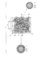
- FIG. 1 is a schematic cross-sectional view of an example of an electrode according to the first embodiment, and a schematic cross-sectional view of active material particles included in each of a first portion and a second portion of an electrode mixture layer.
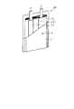
- FIG. 2 is a partially cutaway perspective view of an example nonaqueous electrolyte battery according to the second embodiment.
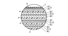
- FIG. 3 is an enlarged cross-sectional view of part A of the nonaqueous electrolyte battery shown in FIG.
- FIG. 4 is a cross-sectional TEM image of a part of the electrode of Example 1-1.
- FIG. 5 is a cross-sectional TEM image of another part of the electrode of Example 1-1.
- an electrode comprising an electrode mixture layer and a current collector carrying the electrode mixture layer on at least one surface.
- the electrode mixture layer includes active material particles containing Li and at least one transition metal selected from the group consisting of Fe, Mn, Co, and Ni.
- the electrode mixture layer includes a first surface in contact with the current collector and a second surface separated from the first surface by the thickness of the electrode mixture layer.
- the electrode mixture layer includes a first portion including a first surface and a second portion including a second surface. The first portion has a thickness of at least 20% of the thickness of the electrode mixture layer. The second portion has a thickness of at least 20% of the thickness of the electrode mixture layer.
- a first oxide layer is formed on the surface of the active material particles.
- the first oxide layer is selected from the group consisting of Li, Mg, Ca, B, Al, Si, P, Fe, Mn, Co, Ni, Cu, Zn, Zr, Nb, Mo, Ta, and W. Contains at least one element.
- the thickness of the first oxide layer is greater than 0.5 nm and less than or equal to 100 nm.
- a second oxide layer is formed on the surface of the active material particles.
- the second oxide layer is selected from the group consisting of Li, Mg, Ca, B, Al, Si, P, Fe, Mn, Co, Ni, Cu, Zn, Zr, Nb, Mo, Ta, and W. Contains at least one element.
- the thickness of the second oxide layer is 0.5 nm or more and less than 100 nm.
- the thickness of the first oxide layer is greater than the thickness of the second oxide layer.
- the present inventors have difficulty in realizing a nonaqueous electrolyte battery capable of exhibiting an excellent capacity maintenance ratio when an electrode manufactured by increasing the density of the electrode mixture layer without considering the capacity maintenance ratio is used. The knowledge that it is.
- the cause is that, when an electrode mixture layer having a high density is used in a non-aqueous electrolyte battery, as the charge / discharge cycle is repeated, the electrode assembly is repeated. It was found that there was a bias in the deterioration of the active material in the material layer.
- the voids in the electrode mixture layer decrease.
- the nonaqueous electrolyte permeability in the electrode mixture layer decreases.
- the non-aqueous electrolyte is less likely to reach the portion near the current collector of the electrode mixture layer than the portion away from the current collector. Therefore, in the electrode mixture layer with few voids, the diffusibility of ions involved in charge / discharge, such as lithium ions, is biased.
- the amount of Li involved in the Li insertion and desorption reactions in the active material tends to be excessive and insufficient in a portion close to the current collector. That is, during the Li insertion reaction, lithium ions existing at the reaction interface between the active material and the non-aqueous electrolyte are likely to be insufficient in the portion of the electrode mixture layer close to the current collector. On the other hand, in the Li elimination reaction, lithium ions existing at the reaction interface between the active material and the non-aqueous electrolyte tend to be excessive in such a portion.
- the portion near the current collector of the electrode mixture layer is likely to deteriorate because the amount of lithium ions tends to be excessive and insufficient as described above.
- An electrode including an electrode mixture in which the deterioration of the active material is biased can cause a decrease in capacity and an increase in resistance. This is the reason why it is difficult to realize a non-aqueous electrolyte battery that can exhibit an excellent capacity retention rate when using an electrode that can be biased in the deterioration of the active material.
- the first oxide layer is formed on the surface of the active material particles included in the first portion of the electrode mixture layer, that is, the portion close to the current collector. This first oxide layer can relieve the overvoltage applied to the surface of the active material particles and prevent the structure of the active material from deteriorating.
- the second oxide layer is also formed on the surface of the active material particles contained in the second portion of the electrode mixture layer, that is, the portion away from the current collector.
- the thickness of the second oxide layer is smaller than the thickness of the first oxide layer.
- the second oxide layer has a smaller thickness than the first oxide layer, but as described above, the portion away from the current collector is a portion near the current collector. Compared to, lithium ion excess and deficiency hardly occurs. Therefore, even with the second oxide layer having a thickness smaller than that of the first oxide layer, the structural deterioration of the active material particles contained in the second portion of the electrode mixture layer can be sufficiently prevented. And since a 2nd oxide layer does not participate in charging / discharging reaction, this 2nd oxide layer with small thickness can prevent the fall of the capacity
- the electrode according to the first embodiment can suppress a shift in the progress of deterioration of the active material between the first portion and the second portion in the electrode mixture layer, and thereby the electrode The bias of deterioration of the active material in the composite layer can be eliminated.
- the electrode according to the first embodiment can achieve such elimination of deterioration while preventing a decrease in the capacitance of the electrode. Thanks to this, the electrode according to the first embodiment can realize a non-aqueous electrolyte battery that can exhibit a high energy density and an excellent capacity retention rate.
- the active material particles contained in the electrode mixture layer include lithium (Li) and at least one transition metal selected from the group consisting of iron (Fe), manganese (Mn), cobalt (Co), and nickel (Ni).
- a composite oxide containing Examples of the composite oxide include lithium manganese composite oxide (for example, LiMn 2 O 4 or LiMnO 2 ), lithium nickel composite oxide (for example, LiNiO 2 ), lithium cobalt composite oxide (LiCoO 2 ), and lithium nickel cobalt composite oxide.
- LiNi 1-x Co x O 2 , 0 ⁇ x ⁇ 1 lithium manganese cobalt composite oxide (for example, LiMn x Co 1-x O 2 , 0 ⁇ x ⁇ 1), lithium iron phosphate (LiFePO 4 ), And lithium composite phosphate compounds (for example, LiMn x Fe 1-x PO 4 , 0 ⁇ x ⁇ 1).
- lithium manganese cobalt composite oxide for example, LiMn x Co 1-x O 2 , 0 ⁇ x ⁇ 1
- LiFePO 4 lithium iron phosphate
- lithium composite phosphate compounds for example, LiMn x Fe 1-x PO 4 , 0 ⁇ x ⁇ 1
- the active material particles may be primary particles or secondary particles obtained by granulating the primary particles.
- the electrode mixture layer can also contain an active material other than the active material particles.
- the electrode mixture layer can further include a conductive agent and a binder.
- the conductive agent can be blended as necessary in order to enhance the current collecting performance and suppress the contact resistance between the active material and the current collector.
- Examples of the conductive agent include acetylene black, carbon black, and graphite.
- the binder can bind the active material and the current collector. Examples of the binder include polytetrafluoroethylene (PTFE), polyvinylidene fluoride (PVdF), fluorine rubber, styrene-butadiene rubber (SBR), polypropylene (PP), polyethylene (PE), and carboxymethyl cellulose (CMC). Can be mentioned. The content of each material in the electrode mixture layer will be described later.
- the electrode mixture layer can have a thickness in the range of 20 ⁇ m to 200 ⁇ m, for example.
- the preferred thickness of the electrode mixture layer is in the range of 20 ⁇ m to 100 ⁇ m.
- the first portion including the first surface in contact with the current collector has a thickness of at least 20% of the thickness of the electrode mixture layer.
- the thickness of the first portion is less than 20% of the thickness of the electrode mixture layer, the bias of deterioration of the active material in the electrode mixture layer cannot be sufficiently eliminated.
- the first portion has a thickness of 50% or less of the thickness of the electrode mixture layer. When the thickness of the first portion is within this range, it is possible to further suppress a decrease in the capacity of the electrode while sufficiently eliminating the bias of deterioration of the active material in the electrode mixture layer.
- the second portion including the second surface of the electrode mixture layer has a thickness of at least 20% of the thickness of the electrode mixture layer.
- the second portion has a thickness of 50% or less of the thickness of the electrode mixture layer.
- the thickness of the second portion is within this range, it is possible to further suppress the decrease in the capacity of the electrode while sufficiently eliminating the bias of deterioration of the active material in the electrode mixture layer.
- a first oxide layer is formed on the surface of the active material particles.
- the first oxide layer includes lithium (Li), magnesium (Mg), calcium (Ca), boron (B), aluminum (Al), silicon (Si), phosphorus (P), iron (Fe), manganese ( Mn), cobalt (Co), nickel (Ni), copper (Cu), zinc (Zn), zirconium (Zr), niobium (Nb), molybdenum (Mo), tantalum (Ta) and tungsten (W) It contains at least one element selected from the above.
- the thickness of the first oxide layer is larger than 0.5 nm and not larger than 100 nm.
- the thickness of the first oxide layer is 0.5 nm or less, the deterioration of the active material particles cannot be sufficiently suppressed in the first portion of the electrode mixture layer, and as a result, during the charge / discharge cycle It is not possible to sufficiently suppress the decrease in capacity and the increase in resistance.
- the thickness of the first oxide layer is greater than 100 nm, the resistance of the first oxide layer increases, and as a result, the input / output characteristics are degraded.
- a second oxide layer is formed on the surface of the active material particles.
- the second oxide layer is selected from the group consisting of Li, Mg, Ca, B, Al, Si, P, Fe, Mn, Co, Ni, Cu, Zn, Zr, Nb, Mo, Ta, and W. Contains at least one element.
- the thickness of the second oxide layer is 0.5 nm or more and smaller than 100 nm.
- the thickness of the second oxide layer is less than 0.5 nm, the deterioration of the active material particles cannot be sufficiently suppressed in the second portion of the electrode mixture layer, and as a result, during the charge / discharge cycle It is not possible to sufficiently suppress the decrease in capacity and the increase in resistance.
- the thickness of the second oxide layer is 100 nm or more, the resistance due to the second oxide layer increases, and as a result, the input / output characteristics are degraded.
- the thickness of the first oxide layer is larger than the thickness of the second oxide layer. If the thickness of the first oxide layer is less than or equal to the thickness of the second oxide layer, the progress of the deterioration of the active material between the first portion and the second portion of the electrode mixture layer The deviation cannot be suppressed.
- the ratio of the thickness of the first oxide layer to the thickness of the second oxide layer is 5 or more. When the ratio of thickness is 5 or more, it is possible to further suppress the deterioration bias in the electrode mixture layer. More preferably, the ratio of the thickness of the first oxide layer to the thickness of the second oxide layer is 200 or less.
- the thickness ratio is 200 or less, the difference in resistance between the first part and the second part can be suppressed, and the active material particles contained in the first part and the active part of the second part can be suppressed. It is possible to suppress the charge / discharge contribution rate from being biased between the substance particles. As a result, a decrease in capacity during the cycle can be further suppressed. More preferably, the ratio of the thickness of the first oxide layer to the thickness of the second oxide layer is 5 or more and 50 or less.
- the first oxide layer and the second oxide layer cover the reaction interface where the Li insertion / elimination reaction occurs.
- the particle surface in the direction perpendicular to the C axis of the crystal axis becomes the Li insertion / desorption reaction interface.
- an oxide layer covering such a reaction interface can be formed by covering the entire surface of the active material particles with an oxide layer.
- such an electrode mixture layer is supported on at least one surface of the current collector. That is, the current collector may carry the electrode mixture layer only on one side, or may carry the electrode mixture layer on both sides. Further, the current collector may include a portion that does not carry the electrode mixture layer. Such a part can be used as an electrode tab, for example.
- a sheet containing a material having high electrical conductivity can be used.
- an aluminum foil or an aluminum alloy foil can be used as the current collector.
- the thickness is, for example, 20 ⁇ m or less, and preferably 15 ⁇ m or less.
- the aluminum alloy foil can include magnesium, zinc, silicon and the like.
- content of transition metals, such as iron, copper, nickel, and chromium contained in aluminum alloy foil is 1% or less.
- two or more types of slurries including a first slurry for the first portion of the electrode mixture layer and a second slurry for the second portion of the electrode mixture layer are prepared.
- the slurry can be prepared, for example, as follows. First, active material particles for the first part and active material particles for the second part are prepared.
- an oxide layer is formed on the surface of the prepared active material particles to obtain an active material composite in which the oxide layer is formed on the surface of the active material particles.
- the oxide layer is activated by, for example, a dry coating method such as a CVD method or a sputtering method, a wet coating method such as a sol-gel method or an electroless plating, or a mixed and pulverized compound processing method such as a ball mill method or a jet mill method. It can be formed on the surface of material particles.
- a dry coating method such as a CVD method or a sputtering method
- a wet coating method such as a sol-gel method or an electroless plating
- a mixed and pulverized compound processing method such as a ball mill method or a jet mill method. It can be formed on the surface of material particles.
- a sol-gel method can be used. Specifically, first, LiNi 0.8 Co 0.2 as active material particles was added to a methanol (CH 3 OH) solution in which nickel acetate (Ni (CH 3 COO) 2 .4H 2 O) as a coating material was uniformly dissolved. O 2 is introduced and stirred. After stirring, the solution is dried to obtain active material particles to which the coating material is attached. After drying, the active material particles to which the coating material is adhered are fired at a temperature of 150 ° C. to 500 ° C. for several minutes to several hours. Thus, an active material composite in which an oxide layer of nickel oxide is formed on the surface of the active material particles LiNi 0.8 Co 0.2 O 2 is obtained.
- the thickness of the first oxide layer formed on the surface of the active material particle for the first portion is set to the second oxide layer formed on the surface of the active material particle for the second portion. Make it larger than the thickness.
- the thickness of the oxide layer can be controlled by complexly adjusting some of the conditions of the oxide formation method. For example, in the case of the previous example, the thickness of the oxide layer can be changed by adjusting the ratio of nickel acetate to the weight of the active material particles. Note that other specific examples of the oxide layer forming method and the thickness adjusting method will be described in detail later.
- the active material composite for the first part obtained as described above is put into an appropriate solvent together with the conductive agent and the binder and stirred.
- a first slurry for the first part is obtained.
- the slurry for the second part is prepared in the same manner as the first slurry, except that the active material composite for the second part is used instead of the active material composite for the first part. be able to.
- the weight ratios of the active material composite, the conductive agent, and the binder to be added to the solvent during the preparation of the slurry are 80 to 95% by weight, 3 to 15% by weight, and 2 to 5% by weight, respectively. It is preferable.
- the first slurry prepared as described above is applied to the surface of the current collector. After coating, the coating film is dried and pressed. In this way, the 1st part of an electrode compound-material layer is obtained.
- the second slurry prepared as described above is applied to the surface of the first portion of the electrode mixture layer. After coating, the coating film is dried and pressed. Thus, the second portion of the electrode mixture layer is obtained, and the electrode according to the first embodiment is obtained.
- the second slurry is applied to the surface of the first portion of the electrode mixture layer.
- the first slurry and the second slurry are applied to the surface of the first portion.
- a further slurry different from that may be applied to form further portions of the electrode composite layer.
- a sol-gel method can be used.
- a coating material corresponding to the target oxide layer to be formed on the surface of the active material particles is selected.
- the selected coating material is put into distilled water and stirred at room temperature for about 10 hours.
- a coating raw material dissolving solution is obtained.
- the positive electrode active material particles are put into the coating raw material dissolving solution and further stirred at room temperature for about 10 hours. A mixed solution is thus obtained.
- the mixing weight ratio of the coating raw material: active material particles: water in the mixed solution is x: 100: 300. That is, x is the weight (g) of the coating material added to 100 g of active material particles.
- the thickness of the finally obtained oxide layer can be changed.
- Table 1 the value of the coating material addition amount x 10 necessary for setting the thickness of the finally obtained oxide layer to 10 nm is shown as a representative value.
- the addition amount x t of the coating material necessary for obtaining an oxide layer having a thickness t (nm) different from 10 nm can be obtained by substituting the target thickness t and the representative value x 10 into the following equation. it can.
- the mixed solution thus obtained is dried at 120 ° C. for 5 hours to obtain a powder. Subsequently, the obtained powder is fired at a temperature of 150 ° C. to 500 ° C. for several minutes to several hours to obtain a powder of active material particles having a target oxide layer having a target thickness formed on the surface. .
- a sol-gel method can be used.
- a coating material and a solvent corresponding to the target oxide layer to be formed on the surface of the active material particles are selected.
- the selected coating material is added to the selected solvent and stirred at room temperature for about 10 hours.
- a coating raw material dissolving solution is obtained.
- the positive electrode active material particles are put into the coating raw material dissolving solution and further stirred at room temperature for about 10 hours. A mixed solution is thus obtained.
- the mixing weight ratio of coating raw material: active material particles: solvent in the mixed solution is set to y: 100: 300.
- y is the addition weight (g) of the coating raw material with respect to 100 g of active material particles.
- the addition amount y By changing the addition amount y, the thickness of the oxide finally obtained can be changed.
- Table 2 shows the values of the addition amount y 10 of coating material required to make the thickness of the finally obtained oxide layer and 10nm as the representative value.
- Amount y t of coating material required to obtain an oxide layer of a different thickness t (nm) and 10nm may be obtained by substituting the thickness t and the representative value y 10 of interest by the following formula it can.
- the mixed solution thus obtained is dried at 70 ° C. for 5 hours to obtain a powder. Subsequently, the obtained powder is fired at a temperature of 150 ° C. to 500 ° C. for several minutes to several hours to obtain a powder of active material particles having a target oxide layer having a target thickness formed on the surface. .
- oxide layer as an example oxide layer of a method for forming a layer of Li 2 O-2B 2 O 3, to form a layer of Li 2 O-2B 2 O 3 on the surface of the active material particles, for example, A combination of dry mixing and heat treatment can be used.
- the predetermined mixing ratio can be calculated by the mixing amount z 10 shown in Table 3 below and the following equation. More specifically, Table 3 shows a representative value of each mixing amount z 10 of the coating raw material necessary for setting the thickness of the finally obtained oxide layer to 10 nm. In addition, each mixing amount z t of the coating raw material necessary to obtain an oxide layer having a thickness t (nm) different from 10 nm is expressed by the following formula: the target thickness t and the representative value z of each coating raw material It can be obtained by substituting 10 .
- the mixture thus obtained is dried at 500 ° C. for 10 hours to obtain a powder of active material particles on the surface of which a Li 2 O-2B 2 O 3 layer having the desired thickness is formed.
- the thickness of the oxide layer can be measured by a transmission electron microscope (Transmission Electron Microscopy: TEM). Below, the specific example of the measuring method of the oxide layer by a transmission electron microscope is demonstrated.
- an electrode to be measured is prepared.
- the electrode incorporated in the nonaqueous electrolyte battery can be prepared by the following procedure. First, the discharged battery is disassembled in an inert atmosphere such as argon. An electrode group is taken out from the disassembled nonaqueous electrolyte battery. The taken-out electrode group is separated into a separator and electrodes that are a positive electrode and a negative electrode using, for example, tweezers. The electrode thus obtained is washed by immersing it in an organic solvent such as ethyl methyl carbonate. After washing, the electrode is dried. Thus, an electrode can be prepared.
- the gap in the electrode mixture layer of the prepared electrode is embedded with resin.
- a surface protective film such as tungsten or platinum is formed on the electrode surface.
- the focused ion beam method using gallium ions (Focused Ion Beam: FIB) is about 10 ⁇ m square and the thickness is 0 Take a flake sample that is 0.05 ⁇ m to 0.2 ⁇ m. Thus, a sample of the second portion of the electrode mixture layer is obtained.
- the electrode mixture layer and the current collector are separated using a knife.
- the cut surface thus cut is irradiated with gallium ions from the vertical direction and subjected to FIB processing to obtain a flake sample having a square of about 10 ⁇ m and a thickness of 0.05 ⁇ m to 0.2 ⁇ m.
- a sample of the first portion of the electrode mixture layer is obtained.
- Acceleration voltage of gallium ions during sampling is 10-40 kV.
- active material particles that are directed in an appropriate observation direction with respect to the transmission electron beam are selected. Execute high-resolution TEM observation at a magnification of 300,000 times or more.
- an appropriate observation direction is a direction in which insertion and desorption of Li ions occur in the active material particles.
- an electron beam is incident from the [100] direction of the crystal axis, and an oxide coated on the (hk0) surface Observe the layer.
- an arbitrary distance from the surface of the oxide layer to the interface between the active material particles and the oxide layer is observed in a direction perpendicular to the crystal axis C-axis and perpendicular to the incident direction of the electron beam. Measure 10 times at different points. The average of the lengths thus measured is taken as the thickness of the oxide layer.
- An active material primary particle having a spinel structure typified by LiMn 2 O 4 is irradiated with an electron beam from the [100] direction of the crystal axis and is coated on the particle surface in the [010] direction. Observe. In the obtained image, the length from the surface of the oxide layer to the interface between the active material particles and the oxide layer is measured 10 times at any different locations in the [010] direction. The average of the lengths thus measured is taken as the thickness of the oxide layer.
- An active material primary particle having an olivine-type iron phosphate structure typified by LiFePO 4 is irradiated with an electron beam from the [100] direction of the crystal axis and is coated on the particle surface in the [010] direction Observe the layer.
- the length from the surface of the oxide layer to the interface between the active material and the oxide layer is measured 10 times at any different locations in the [010] direction. The average of the lengths thus measured is taken as the thickness of the oxide layer.
- the composition of the active material particles can be confirmed by identifying the substance from crystal structure analysis and composition analysis and confirming the distribution from cross-sectional observation. Specifically, for example, it can be confirmed by the following procedure. First, only the electrode mixture layer applied on the current collector is peeled off with a cutter or the like, and an X-ray diffraction pattern is obtained by an X-ray diffraction method using Cu—K ⁇ rays. Information on the crystal structure and lattice constant of the active material is obtained from the diffraction pattern. Next, the metal element composition is quantified using inductively coupled plasma atomic emission spectrometry. Thus, the composition of the active material is confirmed.
- a metal element mapping image of the cross section of the positive electrode using a scanning electron microscope and energy dispersive X-ray spectroscopy (EDX).
- EDX energy dispersive X-ray spectroscopy
- the active material species in each composite layer is confirmed.
- K ⁇ rays of Mn, Fe, Co, and Ni are used.
- the electrode cross section measurement sample is prepared by cross section ion milling using an argon ion source. A piece of about 2 cm ⁇ 2 cm is cut out from the electrode sheet with a cutter or the like, and irradiated with argon ions accelerated at an accelerating voltage of 2 to 6 KV on one section to produce a flat section.
- the composition of the oxide layer can be confirmed using EDX attached to TEM or Electron Energy-Loss Spectroscopy (EELS). Specifically, it can be confirmed by the following procedure.
- the measurement sample is prepared in the same manner as the above-described sample processing for measuring the oxide layer thickness.
- Compositions other than Li and B can be confirmed by using EDX.
- the oxide layer is irradiated with an electron beam accelerated at 200 KV, and Mg—K ⁇ , Ca—K ⁇ , Al—K ⁇ , Si—K ⁇ , P—K ⁇ , Fe—K ⁇ , Mn—K ⁇ , Co—K ⁇ , Ni—K ⁇ ,
- the composition of the metal element is confirmed from Cu-K ⁇ , Zn-K ⁇ , Zr-L ⁇ , Nb-L ⁇ , Mo-L ⁇ , and Ta-M ⁇ .
- Li and B it confirms using EELS.
- the oxide layer is irradiated with an electron beam accelerated at 200 KV, and the composition is confirmed from the peaks of the Li—K absorption edge and the BK absorption edge in the EELS spectrum.
- the thickness of the electrode mixture layer, the thickness of the first portion of the electrode mixture layer, and the thickness of the second portion of the electrode mixture layer can be measured, for example, by the following procedure.
- a thin piece sample is prepared for every about 10% of the thickness of the electrode mixture layer from the surface of the electrode mixture layer to the electrode thickness direction, and the thickness of the oxide layer is measured.
- the measured values of the obtained oxide layer are t10%, t20%, t30%, t40%, t50%, t60%, t70%, t80%, and t90% in order from the surface of the electrode mixture layer.
- the thickness of the first portion of the electrode mixture layer is plotted with the thickness of the oxide layer at each measurement position on the vertical axis and the depth from the surface of the electrode mixture layer of the thin piece sample acquisition site on the horizontal axis.
- T1 T ⁇ Calculate with D1.
- the thickness of the second portion of the electrode mixture layer the value on the vertical axis crosses (1/2) ⁇ (t90% + t10%) or (1/2) ⁇ (t10%) in the above polyline diagram.
- the depth from the surface of the electrode mixture layer is D2, and D2 is the thickness of the second portion of the electrode mixture layer.
- FIG. 1 is a schematic cross-sectional view of an example of an electrode according to the first embodiment, and a schematic cross-sectional view of active material particles respectively included in a first portion and a second portion of an electrode mixture layer.
- the electrode 1 includes a current collector 11 and an electrode mixture layer 12 supported on one side of the current collector 11.
- the electrode mixture layer 12 includes active material particles 120, a conductive agent 130, and a binder 140.
- the active material particles 120 are shown as gray areas
- the conductive agent 130 is shown as a white area
- the binder 140 is shown as a line.
- the electrode mixture layer 12 includes a first surface 12 a in contact with the current collector 11.
- the electrode mixture layer 12 includes a second surface 12b that is separated from the first surface 12a by the thickness T of the electrode mixture layer 12.
- Electrode mixture layer 12 includes a first portion 12 1 that includes a first surface 12a, a second portion 12 2 which includes a second surface 12b.
- the first portion 12 1 of the electrode mixture layer 12 has a thickness T 1 corresponding to 50% of the thickness T of the electrode mixture layer 12.
- the second portion 12 2 of the electrode mixture layer 12 has a thickness T 2 corresponding to 50% of the thickness T of the electrode mixture layer 12.
- the active material particles 120 are covered with the first oxide layer 121 having a thickness of t 1.
- the active material particles 120 are covered with the second oxide layer 122 having a thickness t 2 .
- the thickness t 1 of the first oxide layer 121 is larger than the thickness t 2 of the second oxide layer 122.
- the thickness of the first oxide layer formed on the surface of the active material particles included in the first part of the electrode mixture layer is equal to the second thickness of the electrode mixture layer. It is larger than the thickness of the second oxide layer formed on the surface of the active material particles contained in the portion. Thanks to this, in the electrode according to the first embodiment, it is possible to eliminate the bias of deterioration of the active material in the electrode mixture layer while suppressing a decrease in the capacity of the electrode. That is, the electrode according to the first embodiment can realize a non-aqueous electrolyte battery that can exhibit a high energy density and an excellent capacity retention rate.
- a nonaqueous electrolyte battery includes a positive electrode, a negative electrode, and a nonaqueous electrolyte.
- the positive electrode is an electrode according to the first embodiment.
- the positive electrode is an electrode according to the first embodiment.
- the positive electrode current collector, the electrode mixture layer, and the active material particles are referred to as a positive electrode current collector, a positive electrode mixture layer, and a positive electrode active material particle, respectively.
- the electrode tab that can be included in the current collector of the electrode according to the first embodiment can serve as a positive electrode tab.
- the positive electrode can include a positive electrode tab separate from the positive electrode current collector.
- the negative electrode can include a negative electrode current collector and a negative electrode mixture layer supported on at least one surface of the negative electrode current collector.
- the negative electrode current collector can include a portion that does not carry the negative electrode mixture layer on the surface. This part can serve as a negative electrode tab.
- the negative electrode can include a negative electrode tab separate from the negative electrode current collector.
- the positive electrode and the negative electrode can constitute an electrode group.
- the positive electrode mixture layer and the negative electrode mixture layer can face each other through a separator, for example.
- the electrode group can have various structures.
- the electrode group can have a stacked structure.
- the electrode group having a stack structure can be obtained, for example, by laminating a plurality of positive electrodes and negative electrodes with a separator interposed between a positive electrode mixture layer and a negative electrode mixture layer.
- the electrode group can have a wound structure.
- a wound electrode group is formed by laminating one separator, one positive electrode, another separator, and one negative electrode in this order. It can obtain by winding so that a negative electrode may come outside.
- the nonaqueous electrolyte battery according to the second embodiment can further include a positive electrode terminal and a negative electrode terminal.
- the positive electrode terminal can function as a conductor for electrons to move between the positive electrode and an external circuit by being partially connected to a part of the positive electrode.
- the positive electrode terminal can be connected to, for example, a positive electrode current collector, particularly a positive electrode tab.
- a part of the negative electrode terminal is electrically connected to a part of the negative electrode, whereby the negative electrode terminal can serve as a conductor for electrons to move between the negative electrode and the external terminal.
- the negative electrode terminal can be connected to, for example, a negative electrode current collector, particularly a negative electrode tab.
- the nonaqueous electrolyte battery according to the second embodiment can further include a container.
- the container can contain an electrode group and a non-aqueous electrolyte.
- the non-aqueous electrolyte can be impregnated in the electrode group in the container.
- a part of each of the positive electrode terminal and the negative electrode terminal can be extended from the container.
- the positive electrode, the negative electrode, the nonaqueous electrolyte, the separator, the positive electrode terminal, the negative electrode terminal, and the container will be described in more detail.
- Positive electrode As materials that can be used for the positive electrode, those described in the description of the first embodiment can be used.
- the negative electrode mixture layer that the negative electrode can comprise can include a negative electrode active material, a conductive agent, and a binder.
- negative electrode active material for example, those capable of performing a charge / discharge reaction in combination with active material particles contained in the positive electrode can be used.
- the negative electrode active material it is preferable to use a material capable of proceeding with lithium insertion and desorption reaction at a potential higher by 1 V or more than the oxidation-reduction potential of lithium.
- a negative electrode active material containing such a substance it is possible to suppress the precipitation of lithium dendride accompanying the charge / discharge cycle, and thus it is possible to suppress the reduction of lithium ions in the nonaqueous electrolyte battery system. Thanks to this, such a non-aqueous electrolyte battery can suppress a decrease in the diffusibility of lithium ions in accordance with the charge / discharge cycle, and thus can exhibit a better capacity retention rate.
- lithium titanium oxide An example of a substance capable of proceeding with insertion and elimination of lithium at a potential higher by 1 V or more than the oxidation-reduction potential of lithium is lithium titanium oxide.
- lithium titanium oxide include spinel type lithium titanate (Li 4 + x Ti 5 O 12 (x varies between 0 and 3 depending on the charge / discharge state)) and ramsdellite type lithium titanate ( Li 2 + x Ti 3 O 7 (x varies between 0 and 2 depending on the charge / discharge state))
- Li 2 + x Ti 3 O 7 varies between 0 and 2 depending on the charge / discharge state
- a single type of lithium titanium oxide is used.
- a mixture of two or more lithium titanium oxides may be used.
- the lithium ion storage potential of the lithium titanium oxide is preferably 1 V (vs. Li / Li + ) or more.
- the spinel type lithium titanate and the ramsdellite type lithium titanate have a lithium ion storage potential of 1 V (vs. Li / Li + ) or higher.
- the upper limit of the lithium ion storage potential of the lithium titanium oxide is preferably 2 V or less.
- the average primary particle diameter of the lithium titanium oxide is preferably 5 ⁇ m or less.
- the effective area contributing to the electrode reaction is sufficient, and good large current discharge characteristics can be obtained.
- the lithium titanium oxide preferably has a specific surface area of 1 to 10 m 2 / g.
- the specific surface area is 1 m 2 / g or more, the effective area contributing to the electrode reaction is sufficient, and good large current discharge characteristics can be obtained.
- the specific surface area is 10 m 2 / g or less, the reaction with the non-aqueous electrolyte is suppressed, and the decrease in charge / discharge efficiency and the generation of gas during storage can be suppressed.
- titanium oxide that becomes lithium titanium oxide by charging and discharging.
- examples of the titanium oxide is TiO 2.
- TiO 2 can undergo lithium insertion and desorption reactions at a potential of 1 V (vs. Li / Li + ) or higher.
- a carbon material can be used as the negative electrode active material.
- the conductive agent can be blended as necessary in order to enhance the current collecting performance and suppress the contact resistance between the active material and the current collector.
- Examples of the conductive agent in the negative electrode include a carbon material.
- the carbon material preferably has high alkali metal occlusion and conductivity.
- Examples of carbon materials are acetylene black and carbon black.
- the binder can bind the active material and the current collector.
- the binder in the negative electrode include polytetrafluoroethylene (PTFE), polyvinylidene fluoride (PVdF), fluorine-based rubber, styrene-butadiene rubber (SBR), polypropylene (PP), polyethylene (PE), and carboxymethyl cellulose ( CMC).
- PTFE polytetrafluoroethylene
- PVdF polyvinylidene fluoride
- SBR styrene-butadiene rubber
- PP polypropylene
- PE polyethylene
- CMC carboxymethyl cellulose
- a sheet containing a material having high electrical conductivity can be used.
- an aluminum foil or an aluminum alloy foil can be used as the negative electrode current collector.
- the thickness is, for example, 20 ⁇ m or less, and preferably 15 ⁇ m or less.
- the aluminum alloy foil can include magnesium, zinc, silicon and the like.
- content of transition metals, such as iron, copper, nickel, and chromium contained in aluminum alloy foil is 1% or less.
- the negative electrode can be produced, for example, by the following procedure.
- a negative electrode active material, a conductive agent and a binder are prepared. These are put into a suitable solvent to prepare a negative electrode slurry. At this time, it is preferable that the weight ratios of the negative electrode active material, the negative electrode conductive agent, and the negative electrode binder to be added to the solvent are 70 to 95% by weight, 0 to 20% by weight, and 2 to 10% by weight, respectively.
- the slurry thus obtained is applied to the surface of the negative electrode current collector, dried, and pressed.
- a negative electrode comprising a negative electrode current collector and a negative electrode mixture layer carried on the negative electrode current collector can be obtained.
- Non-aqueous electrolyte contains a non-aqueous solvent and an electrolyte dissolved in the non-aqueous solvent.
- the electrolyte is, for example, an alkali salt, preferably a lithium salt.
- lithium salts include, for example, lithium hexafluorophosphate (LiPF 6 ), lithium tetrafluoroborate (LiBF 4 ), lithium hexafluoroarsenate (LiAsF 6 ), lithium perchlorate (LiClO 4 ), And lithium trifluoromethanesulfonate (LiCF 3 SO 3 ).
- the electrolyte includes lithium hexafluorophosphate (LiPF 6 ) or lithium tetrafluoroborate (LiBF 4 ).
- the concentration of the electrolyte in the nonaqueous electrolytic solution is preferably 0.5 to 2 mol / L.
- the non-aqueous solvent may be a known non-aqueous solvent used for lithium ion batteries.
- a first example of the non-aqueous solvent is a cyclic carbonate such as ethylene carbonate (EC) or propylene carbonate (PC).
- Second examples of non-aqueous solvents are linear carbonates such as dimethyl carbonate, methyl ethyl carbonate and diethyl carbonate; ⁇ -butyrolactone, acetonitrile, methyl propionate, ethyl propionate; cyclic ethers such as tetrahydrofuran and 2-methyltetrahydrofuran; and dimethoxy Chain ethers such as ethane and diethoxyethane.
- the solvent of the second example generally has a lower viscosity than the solvent of the first example.
- the non-aqueous solvent may be a solvent obtained by mixing the solvent of the first example and the solvent of the second example.
- the separator can be made of an insulating material and can prevent electrical contact between the positive electrode and the negative electrode.
- the separator is made of a material through which the electrolyte can pass, or has a shape through which the electrolyte can pass.
- the separator include a synthetic resin nonwoven fabric, a polyethylene porous film, a polypropylene porous film, and a cellulose-based separator.
- Positive electrode terminal and negative electrode terminal As a positive electrode terminal and a negative electrode terminal, what consists of a material with high electrical conductivity is preferable. When connecting to the current collector, these terminals are preferably made of the same material as the current collector in order to reduce contact resistance.
- a laminate film having a thickness of 0.5 mm or less or a metal container having a thickness of 1 mm or less can be used.
- the thickness of the laminate film is more preferably 0.2 mm or less.
- the metal container is more preferably 0.5 mm or less in thickness, and further preferably 0.2 mm or less in thickness.
- the shape of the container includes a flat type (thin type), a square type, a cylindrical type, a coin type, a button type, and the like.
- Examples of the container include an outer packaging material for a small battery that is loaded on a portable electronic device and the like, and an outer packaging material for a large battery that is loaded on a two-wheeled or four-wheeled vehicle, depending on the battery size.
- the laminate film a multilayer film in which a metal layer is interposed between resin layers is used.
- the metal layer is preferably an aluminum foil or an aluminum alloy foil for weight reduction.
- a polymer material such as polypropylene (PP), polyethylene (PE), nylon, polyethylene terephthalate (PET) can be used.
- PP polypropylene
- PE polyethylene
- PET polyethylene terephthalate
- the laminate film can be formed into a container shape by sealing by heat sealing.
- Metal containers are made from aluminum or aluminum alloy.
- the aluminum alloy is preferably an alloy containing elements such as magnesium, zinc, and silicon.
- the alloy contains a transition metal such as iron, copper, nickel, or chromium, the content is preferably 1% by weight or less.
- FIG. 2 is a partially cutaway perspective view of an example nonaqueous electrolyte battery according to the second embodiment.
- FIG. 3 is an enlarged cross-sectional view of part A of the nonaqueous electrolyte battery shown in FIG.
- the nonaqueous electrolyte battery 100 shown in FIGS. 2 and 3 includes a flat electrode group 1.
- the flat electrode group 1 includes a negative electrode 2, a positive electrode 3, and a separator 4.
- the negative electrode 2 includes a negative electrode current collector 21 and a negative electrode mixture layer 22 supported on the negative electrode current collector 21.
- the positive electrode 3 includes a positive electrode current collector 31 and a positive electrode mixture layer 32 supported on the positive electrode current collector 31.
- the positive electrode mixture layer 32 is the same as the electrode mixture layer 12 described with reference to FIG.
- the negative electrode 2 and the positive electrode 3 are laminated with the separator 4 interposed between the negative electrode mixture layer 22 and the positive electrode mixture layer 32.
- Such an electrode group 1 can be obtained by the following procedure. First, one flat negative electrode 2 and one flat positive electrode 3 are laminated with a separator 4 interposed therebetween. Next, another separator 4 is laminated on the positive electrode mixture layer 32 which is not opposed to the negative electrode 2 to make a laminate. The laminate is wound with the negative electrode 2 facing outside. Next, after removing the winding core, press to make it flat. Thus, the electrode group 1 shown in FIGS. 2 and 3 can be obtained.
- a strip-like negative electrode terminal 5 is electrically connected to the negative electrode 2.
- a belt-like positive electrode terminal 6 is electrically connected to the positive electrode 3.
- the nonaqueous electrolyte battery 100 shown in FIGS. 2 and 3 further includes an outer package bag 7 made of a laminate film as a container.
- the electrode group 1 is housed in a laminated film-made outer bag 7 with the ends of the negative electrode terminal 5 and the positive electrode terminal 6 extended from the outer bag 7.
- a non-aqueous electrolyte solution (not shown) is accommodated in the laminated film-made outer bag 7.
- the nonaqueous electrolyte is impregnated in the electrode group 1.
- the nonaqueous electrolyte battery 100 shown in FIGS. 2 and 3 can be manufactured as follows, for example. First, the electrode group 1 is accommodated in the laminated film outer bag 7 with the negative electrode terminal 5 and the positive electrode terminal 6 extended. Then, the peripheral part of the exterior bag 7 is heat-sealed leaving a partial opening. Next, a nonaqueous electrolyte is injected into the outer bag 7 through the opening left previously. After the injection, the non-aqueous electrolyte battery 100 in which the electrode group 1 and the non-aqueous electrolyte solution are sealed in the outer bag 7 can be manufactured by sealing the opening left previously.
- the nonaqueous electrolyte battery according to the second embodiment includes the electrode according to the first embodiment as a positive electrode. Thanks to this, the nonaqueous electrolyte battery according to the second embodiment can exhibit a high energy density and an excellent capacity retention rate. Examples will be described below, but the present invention is not limited to the examples described below as long as the gist of the present invention is not exceeded.
- Example 1-1 the nonaqueous electrolyte battery 100 shown in FIGS. 2 and 3 was produced by the following procedure.
- Lithium nickel cobalt oxide LiNi 0.8 Co 0.2 O 2
- Ni (CH 3 COO) 2 .4H 2 O nickel acetate tetrahydrate
- a coating raw material dissolving solution was obtained.
- the weight ratio of nickel acetate tetrahydrate: lithium nickel cobalt oxide: water in the mixed solution was set to 22: 100: 300.
- the mixed solution thus obtained was dried at 120 ° C. for 5 hours to obtain a powder. Subsequently, the obtained powder was heat-treated at 500 ° C. for 5 hours to obtain a positive electrode active material composite powder.
- this positive electrode active material composite powder was analyzed by the method described above, it was found that it contained lithium nickel cobalt oxide and nickel monoxide (NiO).
- Second Slurry Similar to the first slurry except that a mixed solution was obtained with a weight ratio of nickel acetate tetrahydrate: lithium nickel cobalt oxide: water of 11: 100: 300, A second slurry was prepared.
- the active material composite powder obtained from the mixed solution thus obtained was analyzed by the method described above, it was found that it contained lithium nickel cobalt oxide and nickel monoxide (NiO). It was.
- ⁇ Preparation of negative electrode 2> As a negative electrode active material, 93% by weight of graphite powder and 7% by weight of PVdF were added to NMP and mixed to prepare a slurry. This slurry was applied to both surfaces of a negative electrode current collector 21 made of a copper foil having a thickness of 15 ⁇ m, dried and pressed. During the application, a portion where the slurry was not applied was left on the negative electrode current collector 21. Thus, the negative electrode 2 including the negative electrode current collector 21 and the negative electrode mixture layer 22 supported on both surfaces and having a density of 1.3 g / cm 3 was produced.
- the strip-shaped negative electrode terminal 5 was electrically connected by ultrasonic bonding to the portion of the negative electrode current collector 21 where the slurry was not applied.
- Electrode group 1 After laminating the positive electrode 3 produced as described above, a separator 4 made of a polyethylene porous film having a thickness of 20 ⁇ m, the negative electrode 2 produced as described above, and another separator 4 in this order, The electrode group 1 was produced by winding in a spiral shape so that the negative electrode was located on the outermost periphery. After removing the winding core, the flat electrode group 1 having a width of 58 mm, a height of 95 mm, and a thickness of 3.0 mm was produced by heating and pressing at 90 ° C.
- the obtained electrode group 1 was accommodated in an exterior bag 7 made of a laminate film having a thickness of 0.1 mm, which was composed of an aluminum foil having a thickness of 40 ⁇ m and a polypropylene layer formed on both surfaces of the aluminum foil. .
- an exterior bag 7 made of a laminate film having a thickness of 0.1 mm, which was composed of an aluminum foil having a thickness of 40 ⁇ m and a polypropylene layer formed on both surfaces of the aluminum foil.
- one end of the positive electrode terminal 6 and the negative electrode terminal 5 was extended from the outer bag 7.
- the electrode group 1 stored in the outer bag 7 was vacuum-dried at 80 ° C. for 24 hours.
- the peripheral edge of the outer bag 7 was heat sealed with one end of the positive electrode terminal 6 and the negative electrode terminal 5 extending from the outer bag 7 and leaving a part of the opening.
- Ethylene carbonate (EC) and methyl ethyl carbonate (MEC) were mixed at a volume ratio of 1: 2 to prepare a mixed solvent.
- LiPF 6 lithium hexafluorophosphate
- the nonaqueous electrolyte battery 100 of Example 1-1 was charged at 2.8 V in a 0.2 C rate and 25 ° C. environment, and then discharged at 0.2 C rate until 1.5 V was reached. Thereafter, the battery was charged again at the 1C rate, discharged at the 1C rate, and the initial capacity was measured. Thus, the initial discharge capacity Q 0 was obtained.
- Example 1-1 the nonaqueous electrolyte battery 100 of Example 1-1 was charged and discharged 10,000 times at a 1C rate in a 25 ° C. environment, then charged and discharged once at 1C, and the discharge capacity after cycle deterioration. It was measured Q 1.
- FIG. 4 shows a TEM image of a portion formed using the first slurry in the positive electrode mixture layer 32
- FIG. 5 shows a TEM image of a portion formed using the second slurry.
- the low-lightness region 120 present on the right side is lithium nickel cobalt oxide particles.
- a region R having high brightness existing on the left side in the visual field shown in FIG. 4 is a resin in which the voids of the positive electrode mixture layer 32 are embedded for TEM observation.
- an intermediate brightness region 121 existing between the lithium nickel cobalt oxide particles and the resin is a nickel monoxide layer.
- the length indicated by the arrow in FIG. 4 is the length of the nickel monoxide layer 121 in the direction perpendicular to the C-axis of the lithium nickel cobalt oxide crystal axis and the incident direction of the electron beam, that is, the nickel monoxide layer 121. Is the thickness.
- the thickness t 1 of the nickel monoxide layer 121 in the portion formed using the first slurry was 20 ⁇ m.
- the low-lightness region 120 occupying most of the visual field from the right side is lithium nickel cobalt oxide particles.
- the intermediate brightness region 122 existing between the lithium nickel cobalt oxide particles and the resin is a nickel monoxide layer.
- the length indicated by the arrow in FIG. 5 is the length of the nickel monoxide layer 122 in the direction perpendicular to the C-axis of the lithium nickel cobalt oxide crystal axis and the electron beam incident direction, that is, the nickel monoxide layer 122. Is the thickness.
- the thickness t 2 of the nickel monoxide layer 122 in the portion formed using the second slurry was 10 ⁇ m.
- Example 1-2 to Example 1-23 In Example 1-2 to Example 1-23, the first slurry is prepared so as to obtain the target first oxide layer 121 having the thickness t 1 shown in Table 4 and Table 5 below.
- the preparation conditions of the mixed solution for the above were changed as described above.
- Each of Examples 1-2 to 1-23 is the same as Example 1-1 except that the preparation conditions of the mixed solution for preparing slurry 2 are changed as described above.
- a nonaqueous electrolyte battery 100 was produced.
- Comparative Example 1-1 In Comparative Example 1-1, the positive electrode active material particle powder not treated with nickel acetate was used instead of the positive electrode active material composite powder when the first slurry and the second slurry for producing the positive electrode were produced.
- a nonaqueous electrolyte battery of Comparative Example 1-1 was produced in the same manner as Example 1-1 except that it was used. That is, the nonaqueous electrolyte battery of Comparative Example 1-1 does not include the first oxide layer or the second oxide layer.
- Comparative Example 1-2 In Comparative Example 1-2, except that the positive electrode active material particle powder not treated with nickel acetate was used instead of the positive electrode active material composite powder in the preparation of the first slurry for positive electrode preparation.
- a nonaqueous electrolyte battery of Comparative Example 1-2 was produced in the same manner as Example 1. That is, the nonaqueous electrolyte battery of Comparative Example 1-2 does not include the first oxide layer.
- Comparative Examples 1-3 to 1-5) In Comparative Examples 1-3 to 1-5, the mixing for preparing the first slurry so as to obtain the target first oxide layer 121 having the thickness t 1 shown in Table 6 below.
- the second slurry is prepared so that the preparation conditions of the solution are changed as described above, and the target second oxide layer 122 having the thickness t 2 shown in Table 6 below is obtained.
- the nonaqueous electrolyte batteries of Comparative Examples 1-3 to 1-5 were prepared in the same manner as in Example 1-1 except that the preparation conditions of the mixed solution for the above were changed as described above. did.
- Example 1-2 to Example 1-23 and Comparative Example 1-2 to Comparative Example 1-5 before preparing the first slurry and the second slurry, the same as in Example 1-1, The first oxide layer and the second oxide layer were identified. The results are shown in Tables 4 to 6 below.
- Example 1-2 to Example 1-23 the thickness T of the positive electrode mixture layer 32, the thickness T 1 of the first portion 12 1 of the positive electrode mixture layer 32, and the positive electrode mixture layer 32
- the thickness T 2 of the second portion 12 2 was measured in the same manner as in Example 1-1.
- the thickness T of the positive electrode mixture layer 32, the thickness T 1 of the first portion 12 1 of the positive electrode mixture layer 32, and the thickness T 2 of the second portion 12 2 of the positive electrode mixture layer 32 are: These were the same as those in Example 1-1.
- the nonaqueous electrolyte battery of Example 1-1 is different from the nonaqueous electrolyte battery 100 of Example 1-2 to Example 1-23 and the nonaqueous electrolyte battery of Comparative Example 1-1 to Comparative Example 1-5.
- the capacity retention rate and the thicknesses of the first oxide layer and the second oxide layer were measured in the same procedure as performed for 100. These results are shown in Tables 4 to 6 below. In Tables 4 to 6, the capacity retention rate of each nonaqueous electrolyte battery is shown as a relative value with the nonaqueous electrolyte battery of Comparative Example 1-1 as 100.
- the nonaqueous electrolyte batteries of Comparative Example 1-3 and Comparative Example 1-4 included the first oxide layer and the second oxide layer, but the capacity retention ratios of Examples 1-1 to It was inferior to the nonaqueous electrolyte battery 100 of Example 1-23, and even worse than the nonaqueous electrolyte batteries of Comparative Example 1-1 and Comparative Example 1-2.
- the thickness of the first oxide layer was as large as 200 nm, and thus the resistance due to the first oxide layer was large, and as a result, the deterioration of the second portion of the positive electrode mixture layer proceeded excessively. This is thought to be because of this.
- the nonaqueous electrolyte battery of Comparative Example 1-5 included the first oxide layer and the second oxide layer, but the capacity retention ratio was that of Example 1-1 to Example 1-23. It was inferior to the nonaqueous electrolyte battery 100, and moreover inferior to the nonaqueous electrolyte batteries of Comparative Examples 1-1 to 1-4. This is because the thickness of the second oxide layer is larger than the thickness of the first oxide layer, so that the positive electrode active material between the first portion and the second portion of the positive electrode mixture layer This is probably because the shift in the progress of deterioration could not be suppressed.
- Example 2-1 to Example 2-4 In Example 2-1 to Example 2-4, the positive electrode active material particles were changed to those shown in Table 7 below, and the target first having the thickness t 1 shown in Table 7 below was used. In order to obtain the oxide layer 121, the preparation conditions of the mixed solution for preparing the first slurry were changed as described above, and the target having the thickness t 2 shown in Table 7 below was obtained. Implementation was performed in the same manner as in Example 1-1 except that the preparation conditions of the mixed solution for preparing the second slurry were changed as described above so that the second oxide layer 122 was obtained. Each nonaqueous electrolyte battery 100 of Example 2-1 to Example 2-4 was produced.
- Comparative Examples 2-1 to 2-4 Comparative Examples 2-1 to 2-4
- an oxide layer forming treatment was performed instead of the positive electrode active material composite powder.
- Nonaqueous electrolyte batteries of Comparative Examples 2-1 to 2-4 were fabricated in the same manner as in Examples 2-1 to 2-4, except that the positive electrode active material particle powder that was not used was used. . That is, the nonaqueous electrolyte batteries of Comparative Examples 2-1 to 2-4 did not contain the first oxide layer or the second oxide layer.
- Example 2-1 to Example 2-4 when preparing the first slurry and the second slurry, the first oxide layer and the second oxide were prepared in the same manner as in Example 1-1. The layer was identified. The results are shown in Table 7 below.
- the thickness of the positive-electrode mixture layer 32 T, of the first portion 12 1 of the positive-electrode mixture layer 32 The thickness T 1 and the thickness T 2 of the second portion 12 2 of the positive electrode mixture layer 32 were measured in the same manner as in Example 1-1.
- the thickness T of the positive electrode mixture layer 32, the thickness T 1 of the first portion 12 1 of the positive electrode mixture layer 32, and the thickness T 2 of the second portion 12 2 of the positive electrode mixture layer 32 are: These were the same as those in Example 1-1.
- the nonaqueous electrolyte battery of Example 1-1 is different from the nonaqueous electrolyte battery 100 of Example 2-1 to Example 2-4 and the nonaqueous electrolyte battery of Comparative Example 2-1 to Comparative Example 2-4.
- the capacity retention rate and the thicknesses of the first oxide layer and the second oxide layer were measured in the same procedure as performed for 100. These results are shown in Table 7 below.
- the capacity retention rates of the nonaqueous electrolyte batteries 100 of Examples 2-1 to 2-4 are those of the nonaqueous electrolyte batteries of Comparative Examples 2-1 to 2-4, respectively.
- the relative value is 100.
- the capacity retention rates of the nonaqueous electrolyte batteries 100 of Examples 2-1 to 2-4 are higher than those of the nonaqueous electrolyte batteries of Comparative Examples 2-1 to 2-4, respectively. It can be seen that it is excellent. Further, from the results of Table 7, the non-aqueous electrolyte battery 100 of Example 2 series is different from the non-aqueous electrolyte battery 100 of Example 1 series in positive electrode active material particles, but the non-aqueous electrolyte of Example 1 series is different. It turns out that the effect similar to the battery 100 was able to be exhibited.
- Example 3-1 to Example 3 to 23 and Comparative Example 3-1 to Comparative Example 3-5 In Examples 3-1 to 3-23 and Comparative Examples 3-1 to 3-5, the negative electrode active material was replaced with graphite powder, and the lithium occlusion potential was 1.55 V (vs. Li / Li + ).
- Example 3-1 to Example 3 to 23 and Comparative Example 3-1 to Comparative Example 3-5 specifically, the negative electrode 2 was produced by the following procedure.
- lithium titanate (Li 4 Ti 5 O 12 ) powder of 85% by weight having a lithium occlusion potential of 1.55 V (vs. Li / Li + ), 5% by weight of graphite, and acetylene black 3% by weight and 7% by weight of PVdF were added to NMP and mixed to prepare a slurry.
- This slurry was applied to both surfaces of a negative electrode current collector 21 made of an aluminum foil having a thickness of 11 ⁇ m, dried and pressed. During the application, a portion where the slurry was not applied was left on the negative electrode current collector 21.
- the negative electrode 2 including the negative electrode current collector 21 and the negative electrode mixture layer 22 supported on both surfaces and having a density of 2.0 g / cm 3 was produced.
- the nonaqueous electrolyte battery of Example 1-1 is different from the nonaqueous electrolyte battery 100 of Examples 3-1 to 3 to 23 and the nonaqueous electrolyte batteries of Comparative Examples 3-1 to 3-5.
- the capacity retention rate and the thicknesses of the first oxide layer and the second oxide layer were measured in the same procedure as performed for 100. These results are shown in Tables 8 to 10 below. In Tables 8 to 10, the capacity retention rate of each nonaqueous electrolyte battery is shown as a relative value with the nonaqueous electrolyte battery of Comparative Example 3-1 as 100.
- Example 1 series shown in Tables 4 to 6 and the results of Example 3 series shown in Tables 8 to 10 were compared, the results were obtained using spinel type lithium titanate as the negative electrode active material. It can be seen that the nonaqueous electrolyte battery 100 of Example 3 series was able to achieve a capacity retention rate superior to that of the nonaqueous electrolyte battery 100 of Example 1 series using graphite as the negative electrode active material.
- Example 4-1 to Example 4-4 and Comparative Example 4-1 to Comparative Example 4-4 In Example 4-1 to Example 4-4 and Comparative Example 4-1 to Comparative Example 4-4, the negative electrode active material was changed to graphite powder, and the lithium occlusion potential was 1.55 V (vs. Li / Li + ).
- a spinel type lithium titanate Li 4 Ti 5 O 12
- the negative electrode 2 containing a spinel type lithium titanate as a negative electrode active material was produced in the same procedure as described in Example 3 series.
- the non-aqueous electrolyte battery of Example 1-1 is different from the non-aqueous electrolyte battery of Example 4-1 to Example 4-4 and the non-aqueous electrolyte battery of Comparative Example 4-1 to Comparative Example 4-4.
- the capacity retention ratio and the thicknesses of the first oxide layer and the second oxide layer were measured. These results are shown in Table 11 below.
- the capacity retention rates of the nonaqueous electrolyte batteries 100 of Examples 4-1 to 4-4 are those of the nonaqueous electrolyte batteries 100 of Comparative Examples 4-1 to 4-4, respectively. Is shown as a relative value with 100 as the value.
- the capacity retention rates of the nonaqueous electrolyte batteries 100 of Examples 4-1 to 4-4 are respectively higher than those of the nonaqueous electrolyte batteries of Comparative Examples 4-1 to 4-4. It can be seen that it is excellent. Further, from the results of Table 11, the non-aqueous electrolyte battery 100 of Example 4 series differs from the non-aqueous electrolyte battery 100 of Example 3 series in positive electrode active material particles, but the non-aqueous electrolyte of Example 3 series is different. It turns out that the effect similar to the battery 100 was able to be exhibited.
- Example 2 series shown in Table 7 when comparing the results of Example 2 series shown in Table 7 and the results of Example 4 series shown in Table 11, non-water of Example 4 series using spinel type lithium titanate as the negative electrode active material. It can be seen that the electrolyte battery 100 was able to achieve a capacity retention rate superior to that of the non-aqueous electrolyte battery 100 of Example 2 series using graphite as the negative electrode active material.
- nonaqueous electrolyte batteries of Examples 1-1 to 1-23, Examples 2-1 to 2-4, Examples 3-1 to 3-23, and Examples 4-1 to 4-4 are Even when the density of the positive electrode was increased, an excellent capacity retention rate could be exhibited as described above.
- the thickness of the first oxide layer formed on the surface of the active material particles included in the first portion of the electrode mixture layer is: An electrode larger than the thickness of the second oxide layer formed on the surface of the active material particles contained in the second portion of the electrode mixture layer is provided. This electrode can eliminate the bias of deterioration of the active material in the electrode mixture layer while suppressing the decrease in the capacity of the electrode. Can be realized.
- Electrode 11 ... Current collector, 12 ... Electrode composite material layer, 12a ... 1st surface of electrode composite material layer, 12b ... 2nd surface of electrode composite material layer, 12 1 ... 1st surface of electrode composite material layer 1 part, 12 2 ... 2nd part of electrode mixture layer, 120 ... active material particles, 121 ... 1st oxide layer, 122 ... 2nd oxide layer, 130 ... conductive agent, 140 ... binding 1 ... Electrode group, 2 ... Negative electrode, 21 ... Negative electrode current collector, 22 ... Negative electrode composite material layer, 3 ... Positive electrode, 31 ... Positive electrode current collector, 32 ... Positive electrode composite material layer, 4 ... Separator, 5 ... Negative electrode Terminal, 6 ... positive electrode terminal, 7 ... exterior bag, 100 ... nonaqueous electrolyte battery.
Landscapes
- Chemical & Material Sciences (AREA)
- Chemical Kinetics & Catalysis (AREA)
- Electrochemistry (AREA)
- General Chemical & Material Sciences (AREA)
- Inorganic Chemistry (AREA)
- Engineering & Computer Science (AREA)
- Materials Engineering (AREA)
- Composite Materials (AREA)
- Manufacturing & Machinery (AREA)
- Crystallography & Structural Chemistry (AREA)
- Battery Electrode And Active Subsutance (AREA)
- Secondary Cells (AREA)
Abstract
1つの実施形態によると、電極が提供される。この電極は、電極合材層と電極合材層を少なくとも一方の面に担持した集電体とを具備する。電極合材層はLiと少なくとも一種の遷移金属とを含有する活物質粒子を含む。電極合材層は、集電体に接している第1の面とこの第1の面から電極合材層の厚さTだけ離れた第2の面とを含む。電極合材層は、第1の面を含む第1の部分と第2の面を含む第2の部分とを含む。電極合材層の第1の部分及び第2の部分のそれぞれにおいて、活物質粒子の表面に第1の酸化物層及び第2の酸化物層がそれぞれ形成されている。第1の酸化物層の厚さは、第2の酸化物層の厚さよりも大きい。
Description
本発明の実施形態は、電極及び非水電解質電池に関する。
高エネルギー密度のリチウムイオン二次電池開発において、正極のエネルギー密度を高めることが重要課題である。主に正極活物質、導電剤、結着剤を含む正極合材の密度を増加させることで、正極のエネルギー密度を高めることが可能である。
一方、リチウムイオン二次電池は、優れた容量維持率も要求される。優れた容量維持率を達成するためには、例えば、電極の劣化防止を図ることが考えられる。
本願発明が解決しようとする課題は、高いエネルギー密度及び優れた容量維持率を示すことができる非水電解質電池を実現することができる電極と、高いエネルギー密度及び優れた容量維持率を示すことができる非水電解質電池とを提供することにある。
第1の実施形態によると、電極が提供される。この電極は、電極合材層と、この電極合材層を少なくとも一方の面に担持した集電体とを具備する。電極合材層は、Liと、Fe、Mn、Co及びNiからなる群より選択される少なくとも一種の遷移金属とを含有する活物質粒子を含む。電極合材層は、集電体に接している第1の面と、この第1の面から電極合材層の厚さだけ離れた第2の面とを含む。電極合材層は、第1の面を含む第1の部分と第2の面を含む第2の部分とを含む。第1の部分は、電極合材層の厚さの少なくとも20%の厚さを有する。第2の部分は、電極合材層の厚さの少なくとも20%の厚さを有する。電極合材層の第1の部分において、活物質粒子の表面には、第1の酸化物層が形成されている。第1の酸化物層は、Li、Mg、Ca、B、Al、Si、P、Fe、Mn、Co、Ni、Cu、Zn、Zr、Nb、Mo、Ta及びWからなる群より選択される少なくとも1種の元素を含有する。第1の酸化物層の厚さは、0.5nmより大きく且つ100nm以下である。電極合材層の第2の部分において、活物質粒子の表面には、第2の酸化物層が形成されている。第2の酸化物層は、Li、Mg、Ca、B、Al、Si、P、Fe、Mn、Co、Ni、Cu、Zn、Zr、Nb、Mo、Ta及びWからなる群より選択される少なくとも1種の元素を含有する。第2の酸化物層の厚さは、0.5nm以上であり且つ100nmより小さい。第1の酸化物層の厚さは、第2の酸化物層の厚さよりも大きい。
第2の実施形態によると、非水電解質電池が提供される。この非水電解質電池は、正極と、負極と、非水電解質とを具備する。正極は、第1の実施形態に係る電極である。
以下に、実施の形態について図面を参照しながら説明する。なお、実施の形態を通して共通の構成には同一の符号を付すものとし、重複する説明は省略する。また、各図は実施の形態の説明とその理解を促すための模式図であり、その形状や寸法、比などは実際の装置と異なる個所があるが、これらは以下の説明と公知の技術とを参酌して、適宜設計変更することができる。
(第1の実施形態)
第1の実施形態によると、電極が提供される。この電極は、電極合材層と、この電極合材層を少なくとも一方の面に担持した集電体とを具備する。電極合材層は、Liと、Fe、Mn、Co及びNiからなる群より選択される少なくとも一種の遷移金属とを含有する活物質粒子を含む。電極合材層は、集電体に接している第1の面と、この第1の面から電極合材層の厚さだけ離れた第2の面とを含む。電極合材層は、第1の面を含む第1の部分と第2の面を含む第2の部分とを含む。第1の部分は、電極合材層の厚さの少なくとも20%の厚さを有する。第2の部分は、電極合材層の厚さの少なくとも20%の厚さを有する。電極合材層の第1の部分において、活物質粒子の表面には、第1の酸化物層が形成されている。第1の酸化物層は、Li、Mg、Ca、B、Al、Si、P、Fe、Mn、Co、Ni、Cu、Zn、Zr、Nb、Mo、Ta及びWからなる群より選択される少なくとも1種の元素を含有する。第1の酸化物層の厚さは、0.5nmより大きく且つ100nm以下である。電極合材層の第2の部分において、活物質粒子の表面には、第2の酸化物層が形成されている。第2の酸化物層は、Li、Mg、Ca、B、Al、Si、P、Fe、Mn、Co、Ni、Cu、Zn、Zr、Nb、Mo、Ta及びWからなる群より選択される少なくとも1種の元素を含有する。第2の酸化物層の厚さは、0.5nm以上であり且つ100nmより小さい。第1の酸化物層の厚さは、第2の酸化物層の厚さよりも大きい。
第1の実施形態によると、電極が提供される。この電極は、電極合材層と、この電極合材層を少なくとも一方の面に担持した集電体とを具備する。電極合材層は、Liと、Fe、Mn、Co及びNiからなる群より選択される少なくとも一種の遷移金属とを含有する活物質粒子を含む。電極合材層は、集電体に接している第1の面と、この第1の面から電極合材層の厚さだけ離れた第2の面とを含む。電極合材層は、第1の面を含む第1の部分と第2の面を含む第2の部分とを含む。第1の部分は、電極合材層の厚さの少なくとも20%の厚さを有する。第2の部分は、電極合材層の厚さの少なくとも20%の厚さを有する。電極合材層の第1の部分において、活物質粒子の表面には、第1の酸化物層が形成されている。第1の酸化物層は、Li、Mg、Ca、B、Al、Si、P、Fe、Mn、Co、Ni、Cu、Zn、Zr、Nb、Mo、Ta及びWからなる群より選択される少なくとも1種の元素を含有する。第1の酸化物層の厚さは、0.5nmより大きく且つ100nm以下である。電極合材層の第2の部分において、活物質粒子の表面には、第2の酸化物層が形成されている。第2の酸化物層は、Li、Mg、Ca、B、Al、Si、P、Fe、Mn、Co、Ni、Cu、Zn、Zr、Nb、Mo、Ta及びWからなる群より選択される少なくとも1種の元素を含有する。第2の酸化物層の厚さは、0.5nm以上であり且つ100nmより小さい。第1の酸化物層の厚さは、第2の酸化物層の厚さよりも大きい。
本発明者らは、容量維持率を考慮せずに電極合材層の密度を高めて製造した電極を用いると、優れた容量維持率を示すことができる非水電解質電池を実現することが困難であるという知見を得た。
本発明者らは、鋭意研究の結果、その原因は、以下において詳細に説明するように、高い密度を有する電極合材層を非水電解質電池において用いると、充放電サイクルを繰り返すにつれて、電極合材層において活物質の劣化の偏りが生じることにあることが分かった。
まず、電極合材層の密度が増加するにつれ、電極合材層中の空隙は減少する。空隙が減少すると、電極合材層における非水電解質の浸透性が低下する。その結果、電極合材層のうち集電体に近い部分へは、集電体から離れた部分に比べて、非水電解質が行き届き難くなる。そのため、空隙の少ない電極合材層では、充放電に関与するイオン、例えばリチウムイオンの拡散性に偏りが生じてしまう。
このようにリチウムイオンの拡散性に偏りがある電極合材層では、集電体に近い部分において、活物質でのLi挿入及び脱離反応に関与するLi量に過不足が生じ易くなる。すなわち、Li挿入反応の際に、電極合材層のうち集電体に近い部分では、活物質と非水電解質との反応界面に存在するリチウムイオンが不足し易くなる。一方で、Li脱離反応の際には、このような部分では活物質と非水電解質との上記反応界面に存在するリチウムイオンが過剰になり易い。
一方で、活物質の劣化の原因の1つとしては、リチウムイオンの量に過不足が生じた状態でのLi挿入及び脱離反応が挙げられる。Li挿入反応及びLi脱離反応の何れも、Li濃度が反応律速となる。そのため、活物質と非水電解質との反応界面においてリチウムイオンに過不足が生じた状態でLi挿入反応又はLi脱離反応が起こると、活物質の結晶構造が変質し、活物質が劣化する。例えば、リチウムイオンが不足した状態でLi挿入反応が起こると、活物質に過電圧が印加され、活物質の劣化が促進される。
電極合材層のうち集電体に近い部分は、先に説明したようにリチウムイオンの量に過不足が生じ易いので、劣化し易くなる。活物質の劣化が偏った電極合材を含む電極は、容量の低下及び抵抗上昇を引き起こし得る。これが、このように活物質の劣化が偏り得る電極を用いると、優れた容量維持率を示すことができる非水電解質電池を実現することが困難になる理由である。
第1の実施形態に係る電極では、電極合材層のうち第1の部分、すなわち集電体に近い部分に含まれる活物質粒子の表面に、第1の酸化物層が形成されている。この第1の酸化物層は、活物質粒子の表面に印加される過電圧を緩和させ、活物質の構造劣化を防ぐことができる。
一方、電極合材層のうち第2の部分、すなわち集電体から離れた部分に含まれる活物質粒子の表面にも、第2の酸化物層が形成されている。ここで、第2の酸化物層の厚さは、第1の酸化物層の厚さよりも小さい。このように第2の酸化物層は第1の酸化物層よりも小さな厚さを有しているが、先に説明したように、集電体から離れた部分は、集電体に近い部分に比べてリチウムイオンの過不足が生じ難い。そのため、厚さが第1の酸化物層よりも小さな第2の酸化物層でも、電極合材層の第2の部分に含まれる活物質粒子の構造劣化を十分に防ぐことができる。そして、第2の酸化物層は充放電反応に関与しないので、厚さの小さなこの第2の酸化物層は、電極の容量の低下を防ぐことができる。
すなわち、第1の実施形態に係る電極は、電極合材層における第1の部分と第2の部分との間での活物質の劣化の進行のずれを抑制することができ、それにより、電極合材層における活物質の劣化の偏りを解消することができる。また、第1の実施形態に係る電極は、このような劣化の偏りの解消を、電極の容量の低下を防ぎながら達成することができる。そのおかげで、第1の実施形態に係る電極は、高いエネルギー密度及び優れた容量維持率を示すことができる非水電解質電池を実現することができる。
次に、第1の実施形態に係る電極を、より詳細に説明する。
電極合材層に含まれる活物質粒子は、リチウム(Li)と、鉄(Fe)、マンガン(Mn)、コバルト(Co)及びニッケル(Ni)からなる群より選択される少なくとも一種の遷移金属とを含有する複合酸化物を含む。複合酸化物としては、例えば、リチウムマンガン複合酸化物(例えばLiMn2O4またはLiMnO2)、リチウムニッケル複合酸化物(例えばLiNiO2)、リチウムコバルト複合酸化物(LiCoO2)、リチウムニッケルコバルト複合酸化物(例えばLiNi1-xCoxO2、0<x≦1)、リチウムマンガンコバルト複合酸化物(例えばLiMnxCo1-xO2、0<x≦1)、リチウムリン酸鉄(LiFePO4)、及びリチウム複合リン酸化合物(例えばLiMnxFe1-xPO4、0<x≦1)が挙げられる。このような複合酸化物は、優れたエネルギー密度を提供することができる。
活物質粒子は、一次粒子であってもよいし、又は一次粒子を造粒して得られる二次粒子であってもよい。
電極合材層は、上記活物質粒子以外の活物質を含むこともできる。
また、電極合材層は、導電剤及び結着剤を更に含むことができる。導電剤は、集電性能を高め、且つ活物質と集電体との接触抵抗を抑えるために必要に応じて配合することができる。導電剤としては、例えば、アセチレンブラック、カーボンブラック及び黒鉛を挙げることができる。結着剤は、活物質と集電体とを結着させることができる。結着剤としては、例えば、ポリテトラフルオロエチレン(PTFE)、ポリフッ化ビニリデン(PVdF)、フッ素系ゴム、スチレン-ブタジエンゴム(SBR)、ポリプロピレン(PP)、ポリエチレン(PE)及びカルボキシメチルセルロース(CMC)を挙げることができる。電極合材層における各材料の含有量については、後述する。
電極合材層は、例えば、20μm~200μmの範囲内にある厚さを有することができる。電極合材層の好ましい厚さは、20μm~100μmの範囲内である。
このような電極合材層のうち、集電体に接している第1の面を含む第1の部分は、電極合材層の厚さの少なくとも20%の厚さを有する。第1の部分の厚さが電極合材層の厚さの20%未満であると、電極合材層における活物質の劣化の偏りを十分に解消することができない。好ましくは、第1の部分は、電極合材層の厚さの50%以下の厚さを有する。第1の部分の厚さがこの範囲内にある場合、電極合材層における活物質の劣化の偏りを十分に解消しながら、電極の容量の低下を更に抑えることができる。
電極合材層のうち第2の面を含む第2の部分は、電極合材層の厚さの少なくとも20%の厚さを有する。第2の部分の厚さが電極合材層の厚さの20%未満であると、電極の容量の低下を十分に抑えることができない。好ましくは、第2の部分は、電極合材層の厚さの50%以下の厚さを有する。第2の部分の厚さがこの範囲内にある場合、電極合材層における活物質の劣化の偏りを十分に解消しながら、電極の容量の低下を更に抑えることができる。
電極合材層の第1の部分において、活物質粒子の表面には、第1の酸化物層が形成されている。第1の酸化物層は、リチウム(Li)、マグネシウム(Mg)、カルシウム(Ca)、ホウ素(B)、アルミニウム(Al)、ケイ素(Si)、リン(P)、鉄(Fe)、マンガン(Mn)、コバルト(Co)、ニッケル(Ni)、銅(Cu)、亜鉛(Zn)、ジルコニウム(Zr)、ニオブ(Nb)、モリブデン(Mo)、タンタル(Ta)及びタングステン(W)からなる群より選択される少なくとも1種の元素を含有する。
この第1の酸化物層の厚さは、0.5nmよりも大きく且つ100nm以下である。第1の酸化物層の厚さが0.5nm以下である場合、電極合材層の第1の部分において、活物質粒子の劣化を十分に抑えることができず、その結果、充放電サイクル時の容量低下と抵抗上昇とを十分に抑制することができない。また、第1の酸化物層の厚さが100nmよりも大きいと、第1の酸化物層による抵抗が大きくなり、その結果、入出力特性の低下を引き起こしてしまう。
電極合材層の第2の部分において、活物質粒子の表面には、第2の酸化物層が形成されている。第2の酸化物層は、Li、Mg、Ca、B、Al、Si、P、Fe、Mn、Co、Ni、Cu、Zn、Zr、Nb、Mo、Ta及びWからなる群より選択される少なくとも1種の元素を含有する。
この第2の酸化物層の厚さは、0.5nm以上であり且つ100nmより小さい。第2の酸化物層の厚さが0.5nm未満である場合、電極合材層の第2の部分において、活物質粒子の劣化を十分に抑えることができず、その結果、充放電サイクル時の容量低下と抵抗上昇とを十分に抑制することができない。また、第2の酸化物層の厚さが100nm以上であると、第2の酸化物層による抵抗が大きくなり、その結果、入出力特性の低下を引き起こしてしまう。
更に、先に説明したように、第1の酸化物層の厚さは第2の酸化物層の厚さよりも大きい。第1の酸化物層の厚さが第2の酸化物層の厚さ以下であると、電極合材層の第1の部分と第2の部分との間での活物質の劣化の進行のずれを抑制することができない。好ましくは、第1の酸化物層の厚さの第2の酸化物層の厚さに対する比は5以上である。厚さの比が5以上である場合、電極合材層における劣化の偏りを更に抑制することができる。より好ましくは、第1の酸化物層の厚さの第2の酸化物層の厚さに対する比は200以下である。厚さの比が200以下である場合、第1の部分と第2の部分との間の抵抗の差を抑えることができ、第1の部分に含まれる活物質粒子と第2の部分の活物質粒子との間で充放電寄与率が偏ることを抑えることができる。その結果、サイクル時の容量の低下をより抑制することができる。更に好ましくは、第1の酸化物層の厚さの第2の酸化物層の厚さに対する比は、5以上50以下である。
第1の酸化物層及び第2の酸化物層は、Li挿入脱離反応が生じる反応界面を覆っていることが好ましい。例えば、LiNiO2及びLiCoO2に代表される層状岩塩型構造を有する活物質では、結晶軸のC軸に対して垂直な方向の粒子表面がLi挿入脱離反応界面となる。このような反応界面を酸化物層により覆うことによって、活物質粒子の劣化を更に抑制することができる。例えば、活物質粒子の表面全体を酸化物層で覆うことにより、このような反応界面を覆う酸化物層を形成することができる。
第1の実施形態において、このような電極合材層は、集電体の少なくとも一方の面に担持される。すなわち、集電体は、一方の面のみに電極合材層を担持してもよいし、又は両方の面に電極合材層を担持してもよい。また、集電体は、電極合材層を担持していない部分を含んでもよい。このような部分は、例えば、電極タブとして使用することができる。
集電体としては、電気伝導性の高い材料を含むシートを使用することができる。例えば、集電体として、アルミニウム箔またはアルミニウム合金箔を使用することができる。アルミニウム箔またはアルミニウム合金箔を使用する場合、その厚さは、例えば20μm以下であり、好ましくは15μm以下である。アルミニウム合金箔には、マグネシウム、亜鉛、ケイ素等を含めることができる。また、アルミニウム合金箔に含まれる、鉄、銅、ニッケル、クロムといった遷移金属の含有量は1%以下であることが好ましい。
次に、第1の実施形態に係る電極を製造する方法の例を説明する。
まず、電極合材層の第1の部分のための第1のスラリーと、電極合材層の第2の部分のための第2のスラリーとを含む、2種類以上のスラリーを調製する。
スラリーは、例えば、以下のようにして調製することができる。
まず、第1の部分のための活物質粒子と第2の部分のための活物質粒子をそれぞれ準備する。
まず、第1の部分のための活物質粒子と第2の部分のための活物質粒子をそれぞれ準備する。
続いて、準備した活物質粒子の表面に、酸化物層を形成して、活物質粒子の表面に酸化物層が形成した活物質複合体を得る。
酸化物層は、例えば、CVD法、スパッタ法などの乾式被覆処理方法、ゾルゲル法、無電解めっきなどの湿式被覆処理方法、ボールミル法、ジェットミル法などの混合・粉砕複合化処理方法により、活物質粒子の表面に形成することができる。
一例を挙げると、活物質粒子LiNi0.8Co0.2O2の表面に一酸化ニッケル(NiO)を形成する場合、ゾルゲル法を用いることができる。具体的には、まず、被覆材料である酢酸ニッケル(Ni(CH3COO)2・4H2O)を均一に溶解させたメタノール(CH3OH)溶液に、活物質粒子であるLiNi0.8Co0.2O2を導入し攪拌する。撹拌後、溶液を乾燥させて、被覆材料が付着した活物質粒子が得られる。乾燥後、被覆材料が付着した活物質粒子を150℃~500℃の温度で、数分から数時間焼成する。かくして、活物質粒子LiNi0.8Co0.2O2の表面に酸化ニッケルの酸化物層が形成した活物質複合体が得られる。
ここで、第1の部分のための活物質粒子の表面に形成させる第1の酸化物層の厚さを、第2の部分のための活物質粒子の表面に形成させる第2の酸化物層の厚さよりも大きくする。酸化物層の厚さは、酸化物形成方法の条件の幾つかを複合的に調整することで制御することができる。例えば、先の例の場合、酸化物層の厚さは、酢酸ニッケルと活物質粒子の重量との比を調整することで変えることができる。
なお、酸化物層の形成方法及び厚さの調製方法の他の具体例については、後に詳述する。
なお、酸化物層の形成方法及び厚さの調製方法の他の具体例については、後に詳述する。
さて、以上のようにして得られた第1の部分のための活物質複合体を、導電剤及び結着剤と共に、適切な溶媒に投入して撹拌する。かくして、第1の部分のための第1のスラリーが得られる。第2の部分のためのスラリーは、第1の部分のための活物質複合体に変えて第2の部分のための活物質複合体を用いること以外、第1のスラリーと同様にして調製することができる。
スラリーの調製の際に溶媒に投入する活物質複合体、導電剤、及び結着剤の重量の割合は、それぞれ、80~95重量%、3~15重量%、及び2~5重量%とすることが好ましい。
次いで、集電体の表面に、上記のようにして調製した第1のスラリーを塗布する。塗布後、塗膜を乾燥させ、プレスする。かくして、電極合材層の第1の部分が得られる。
次いで、電極合材層の第1の部分の表面に、上記のようにして調製した第2のスラリーを塗布する。塗布後、塗膜を乾燥させ、プレスする。かくして、電極合材層の第2の部分が得られ、第1の実施形態に係る電極が得られる。
なお、以上に説明した製造方法の例では、電極合材層の第1の部分の表面に第2のスラリーを塗布したが、第1の部分の表面に例えば第1のスラリー及び第2のスラリーとは異なる更なるスラリーを塗布して、電極合材層の更なる部分を形成してもよい。
<酸化物層の形成方法の具体例>
以下に、活物質粒子の表面に第1の酸化物層及び第2の酸化物層を形成する方法及びこれらの酸化物層の厚さの制御方法の具体例の幾つかを説明する。
以下に、活物質粒子の表面に第1の酸化物層及び第2の酸化物層を形成する方法及びこれらの酸化物層の厚さの制御方法の具体例の幾つかを説明する。
1.酸化物層として、NiO、CoO、MnO、MgO、CaO、AlPO4、Fe3O4、CuO、ZnO又はLi4P2O7の層を形成する方法の例
酸化物層としてNiO、CoO、MnO、MgO、CaO、AlPO4、Fe3O4、CuO、ZnO又はLi4P2O7の層を活物質粒子の表面に形成するには、例えば、ゾル-ゲル法を用いることができる。
酸化物層としてNiO、CoO、MnO、MgO、CaO、AlPO4、Fe3O4、CuO、ZnO又はLi4P2O7の層を活物質粒子の表面に形成するには、例えば、ゾル-ゲル法を用いることができる。
ゾル-ゲル法による上記酸化物層の形成方法の例を以下に示す。
まず、以下の表1を参照して、活物質粒子の表面に形成させたい目的の酸化物層に対応した被覆原料を選択する。選択した被覆原料を蒸留水に投入し、室温にて10時間程度撹拌する。かくして、被覆原料溶解溶液を得る。
まず、以下の表1を参照して、活物質粒子の表面に形成させたい目的の酸化物層に対応した被覆原料を選択する。選択した被覆原料を蒸留水に投入し、室温にて10時間程度撹拌する。かくして、被覆原料溶解溶液を得る。
次いで、正極活物質粒子を被覆原料溶解溶液に投入して、室温にて更に約10時間撹拌する。かくして混合溶液を得る。
ここで、混合溶液における被覆原料:活物質粒子:水の混合重量比をx:100:300とする。すなわち、xは、活物質粒子100gに対する被覆原料の添加重量(g)である。添加量xを変えることで、最終的に得られる酸化物層の厚さを変えることができる。以下の表1には、最終的に得られる酸化物層の厚さを10nmとするために必要な被覆原料の添加量x10の値を代表値として示している。10nmとは異なる厚さt(nm)の酸化物層を得るために必要な被覆原料の添加量xtは、下記式に目的の厚さt及び代表値x10を代入することで得ることができる。
xt = x10 × t/10

かくして得られた混合溶液を120℃で5時間乾燥させ、粉末を得る。次いで、得られた粉末を150℃~500℃の温度で数分から数時間焼成することで、目的の厚さを有した目的の酸化物層が表面に形成された活物質粒子の粉末が得られる。
2.酸化物層として、ZrO2、Nb2O5、MoO3、Ta2O5、WO3、SiO2、又はAl2O3の層を形成する方法の例
酸化物層として、ZrO2、Nb2O5、MoO3、Ta2O5、WO3、SiO2、又はAl2O3の層を活物質粒子の表面に形成するには、例えば、ゾル-ゲル法を用いることができる。
酸化物層として、ZrO2、Nb2O5、MoO3、Ta2O5、WO3、SiO2、又はAl2O3の層を活物質粒子の表面に形成するには、例えば、ゾル-ゲル法を用いることができる。
ゾル-ゲル法による上記酸化物層の形成方法の例を以下に示す。
まず、以下の表2を参照して、活物質粒子の表面に形成させたい目的の酸化物層に対応した被覆原料及び溶媒を選択する。選択した被覆原料を選択した溶媒に投入し、室温にて10時間程度撹拌する。かくして、被覆原料溶解溶液を得る。
まず、以下の表2を参照して、活物質粒子の表面に形成させたい目的の酸化物層に対応した被覆原料及び溶媒を選択する。選択した被覆原料を選択した溶媒に投入し、室温にて10時間程度撹拌する。かくして、被覆原料溶解溶液を得る。
次いで、正極活物質粒子を被覆原料溶解溶液に投入して、室温にて更に約10時間撹拌する。かくして混合溶液を得る。
ここで、混合溶液における被覆原料:活物質粒子:溶媒の混合重量比をy:100:300とする。yは、活物質粒子100gに対する被覆原料の添加重量(g)である。添加量yを変えることで、最終的に得られる酸化物の厚さを変えることができる。以下の表2には、最終的に得られる酸化物層の厚さを10nmとするために必要な被覆原料の添加量y10の値を代表値として示している。10nmとは異なる厚さt(nm)の酸化物層を得るために必要な被覆原料の添加量ytは、下記式に目的の厚さt及び代表値y10を代入することで得ることができる。
yt = y10 × t/10

かくして得られた混合溶液を70℃で5時間乾燥させ、粉末を得る。次いで、得られた粉末を150℃~500℃の温度で数分から数時間焼成することで、目的の厚さを有した目的の酸化物層が表面に形成された活物質粒子の粉末が得られる。
3.酸化物層として、Li2O-2B2O3の層を形成する方法の例
酸化物層として、Li2O-2B2O3の層を活物質粒子の表面に形成するには、例えば、乾式混合及び熱処理の組み合わせを用いることができる。
酸化物層として、Li2O-2B2O3の層を活物質粒子の表面に形成するには、例えば、乾式混合及び熱処理の組み合わせを用いることができる。
乾式混合及び熱処理の組み合わせによるLi2O-2B2O3の層の形成方法の例を以下に示す。
まず、活物質粒子と、水酸化リチウムLiOH・H2Oの粉末と、ホウ酸H3BO3の粉末とを、目的のLi2O-2B2O3の層の厚さを得るための所定の重量比で混合する。
まず、活物質粒子と、水酸化リチウムLiOH・H2Oの粉末と、ホウ酸H3BO3の粉末とを、目的のLi2O-2B2O3の層の厚さを得るための所定の重量比で混合する。
ここで、所定の混合比とは、以下の表3に示す混合量z10及び下記式により算出することができる。具体的に述べると、表3には、最終的に得られる酸化物層の厚さを10nmとするのに必要な被覆原料のそれぞれの混合量z10の値を代表値として示している。また、10nmとは異なる厚さt(nm)の酸化物層を得るために必要な被覆原料のそれぞれの混合量ztは、下記式に目的の厚さt及びそれぞれの被覆原料の代表値z10を代入することで得ることができる。
zt = z10 × t/10
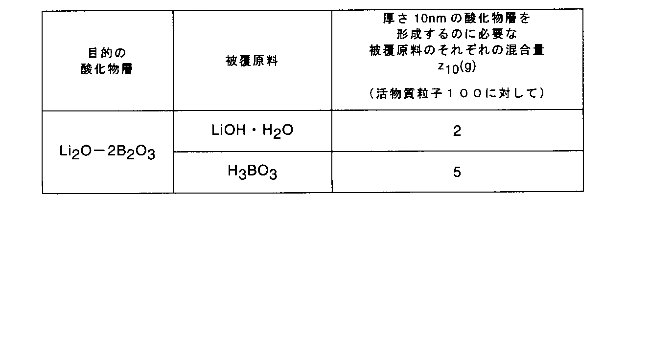
かくして得られた混合物を500℃で10時間乾燥させることにより、目的の厚さを有したLi2O-2B2O3の層が表面に形成された活物質粒子の粉末が得られる。
<第1の酸化物層の厚さ及び第2の酸化物層の厚さの測定方法>
次に、第1の酸化物層の厚さ及び第2の酸化物層の厚さの測定方法について説明する。
次に、第1の酸化物層の厚さ及び第2の酸化物層の厚さの測定方法について説明する。
酸化物層の厚さは、透過型電子顕微鏡(Transmission Electron Microscopy : TEM)によって測定することができる。以下に、透過型電子顕微鏡による酸化物層の測定方法の具体例について説明する。
(1)サンプリング
まず、測定対象たる電極を準備する。非水電解質電池に組み込まれている電極は、以下の手順で準備することができる。初めに、放電処理を施した電池をアルゴンなどの不活性雰囲気下において解体する。解体した非水電解質電池から電極群を取り出す。取り出した電極群を、例えばピンセットを用いるなどして、セパレータと、正極及び負極である電極とに分離する。かくして得られた電極を、エチルメチルカーボネートなどの有機溶剤に浸して、洗浄する。洗浄後、電極を乾燥させる。かくして、電極が準備できる。
まず、測定対象たる電極を準備する。非水電解質電池に組み込まれている電極は、以下の手順で準備することができる。初めに、放電処理を施した電池をアルゴンなどの不活性雰囲気下において解体する。解体した非水電解質電池から電極群を取り出す。取り出した電極群を、例えばピンセットを用いるなどして、セパレータと、正極及び負極である電極とに分離する。かくして得られた電極を、エチルメチルカーボネートなどの有機溶剤に浸して、洗浄する。洗浄後、電極を乾燥させる。かくして、電極が準備できる。
準備した電極の電極合材層の空隙を、樹脂を用いて包埋する。次いで、例えばタングステンや白金などの表面保護膜を電極表面に形成する。保護被膜により被覆された電極の表面、すなわち電極合材層の第2の部分から、ガリウムイオンを用いた収束イオンビーム法(Focused Ion Beam : FIB)によって、約10μm角であり、厚さが0.05μm~0.2μmである薄片サンプルを採取する。かくして、電極合材層の第2の部分の試料が得られる。
次いで、準備した電極において、ナイフを用いて電極合材層と集電体とを切り離す。このようにして切り離した切断面に対して垂直方向からガリウムイオンを照射してFIB加工を施して、約10μm角であり、厚さが0.05μm~0.2μmである薄片サンプルを採取する。かくして、電極合材層の第1の部分の試料が得られる。
サンプリングの際のガリウムイオンの加速電圧は、10~40kVとする。
(2)測定
上記のようにして得られた電極合材層の第1の部分の試料及び第2の部分の試料から透過電子線に対して適切な観察方向を向いた活物質粒子を選択し、倍率30万倍以上の高分解能TEM観察を実施する。ここで、適切な観察方向とは、活物質粒子においてLiイオンの挿入及び脱離が起こる方向である。
上記のようにして得られた電極合材層の第1の部分の試料及び第2の部分の試料から透過電子線に対して適切な観察方向を向いた活物質粒子を選択し、倍率30万倍以上の高分解能TEM観察を実施する。ここで、適切な観察方向とは、活物質粒子においてLiイオンの挿入及び脱離が起こる方向である。
例えば、LiNiO2やLiCoO2に代表される層状岩塩型構造を有する活物質一次粒子に対しては、結晶軸の[100]方向から電子線を入射し、(hk0)表面に被覆された酸化物層を観察する。得られた像において、酸化物層の表面から活物質粒子と酸化物層との界面までを、結晶軸のC軸に垂直であり且つ電子線の入射方向に垂直である方向に向かって任意の異なる箇所で10回測長する。かくして測定した長さの平均を酸化物層の厚みとする。
LiMn2O4に代表されるスピネル型構造を有する活物質一次粒子に対しては、結晶軸の[100]方向から電子線を入射し、[010]方向の粒子表面に被覆された酸化物層を観察する。得られた像において、酸化物層の表面から活物質粒子と酸化物層との界面までを、[010]方向に任意の異なる箇所で10回測長する。かくして測定した長さの平均を酸化物層の厚みとする。
LiFePO4に代表されるオリビン型リン酸鉄構造を有する活物質一次粒子に対しては、結晶軸の[100]方向から電子線を入射し、[010]方向の粒子表面に被覆された酸化物層を観察する。得られた像において、酸化物層の表面から活物質と酸化物層との界面までを、[010]方向に任意の異なる箇所で10回測長する。かくして測定した長さの平均を酸化物層の厚みとする。
次に、活物質粒子並びに第1及び第2の酸化物層の組成の確認方法について説明する。
(活物質粒子について)
活物質粒子の組成は、結晶構造解析、組成分析から物質を同定し、断面観察から分布を確認することで確認することができる。具体的には、例えば以下の手順で確認することができる。まず、集電体上に塗布された電極合材層のみをカッターなどで剥ぎ取り、Cu-Kα線を用いたX線回折法によりX線回折パターンを取得する。回折パターンから活物質の結晶構造と格子定数の情報を得る。次に誘導結合プラズマ発光分析を用いて金属元素組成を定量化する。かくして、活物質の組成を確認する。電極合材層ごとに異なる活物質を使用する場合には、さらに走査電子顕微鏡とエネルギー分散型X線分光法(Energy Dispersive X-ray Spectroscopy:EDX)を用いて正極断面の金属元素マッピング像を取得し各合材層における活物質種を確認する。金属元素の同定にはMn、Fe,Co,NiそれぞれのKα線を利用する。電極断面測定用サンプルはアルゴンイオン源による断面イオンミリングにより作製する。電極シートからカッターなどで約2cm×2cmの断片を切り出し、1断面に対して加速電圧2~6KVで加速したアルゴンイオンを照射して平坦な断面を作製する。
活物質粒子の組成は、結晶構造解析、組成分析から物質を同定し、断面観察から分布を確認することで確認することができる。具体的には、例えば以下の手順で確認することができる。まず、集電体上に塗布された電極合材層のみをカッターなどで剥ぎ取り、Cu-Kα線を用いたX線回折法によりX線回折パターンを取得する。回折パターンから活物質の結晶構造と格子定数の情報を得る。次に誘導結合プラズマ発光分析を用いて金属元素組成を定量化する。かくして、活物質の組成を確認する。電極合材層ごとに異なる活物質を使用する場合には、さらに走査電子顕微鏡とエネルギー分散型X線分光法(Energy Dispersive X-ray Spectroscopy:EDX)を用いて正極断面の金属元素マッピング像を取得し各合材層における活物質種を確認する。金属元素の同定にはMn、Fe,Co,NiそれぞれのKα線を利用する。電極断面測定用サンプルはアルゴンイオン源による断面イオンミリングにより作製する。電極シートからカッターなどで約2cm×2cmの断片を切り出し、1断面に対して加速電圧2~6KVで加速したアルゴンイオンを照射して平坦な断面を作製する。
(酸化物層について)
酸化物層の組成は、TEMに付属したEDXもしくは電子エネルギー損失分光法(Electron Energy‐Loss Spectroscopy:EELS)を用いて確認することができる。具体的には、以下の手順で確認することができる。測定用サンプルは上述の酸化物層厚み測定用サンプル加工と同様にして作製する。EDXを用いることでLiとB以外の組成について確認することができる。200KVで加速された電子線を酸化物層に照射しMg-Kα、Ca-Kα、Al-Kα、Si-Kα、P-Kα、Fe-Kα、Mn-Kα、Co-Kα、Ni-Kα、Cu-Kα、Zn-Kα、Zr-Lα、Nb-Lα、Mo-Lα、Ta-Mαから金属元素の組成を確認する。LiとBとについてはEELSを用いて確認する。200KVで加速された電子線を酸化物層に照射し、EELSスペクトルにおいてLi-K吸収端、B-K吸収端のピークから組成を確認する。
酸化物層の組成は、TEMに付属したEDXもしくは電子エネルギー損失分光法(Electron Energy‐Loss Spectroscopy:EELS)を用いて確認することができる。具体的には、以下の手順で確認することができる。測定用サンプルは上述の酸化物層厚み測定用サンプル加工と同様にして作製する。EDXを用いることでLiとB以外の組成について確認することができる。200KVで加速された電子線を酸化物層に照射しMg-Kα、Ca-Kα、Al-Kα、Si-Kα、P-Kα、Fe-Kα、Mn-Kα、Co-Kα、Ni-Kα、Cu-Kα、Zn-Kα、Zr-Lα、Nb-Lα、Mo-Lα、Ta-Mαから金属元素の組成を確認する。LiとBとについてはEELSを用いて確認する。200KVで加速された電子線を酸化物層に照射し、EELSスペクトルにおいてLi-K吸収端、B-K吸収端のピークから組成を確認する。
電極合材層の厚さ、電極合材層の第1の部分の厚さ、及び電極合材層の第2の部分の厚さは、例えば以下の手順で測定することができる。
FIBを用いて電極合材層の表面から電極厚み方向に電極合材層の厚さの約10%ごとに薄片サンプルを作製し、酸化物層の厚みを測定する。得られた酸化物層の測定値を電極合材層の表面から順にt10%、t20%、t30%、t40%、t50%、t60%、t70%、t80%及びt90%とする。電極合材層の第1の部分の厚さは、各測定位置における酸化物層の厚さを縦軸に、薄片サンプル取得部位の電極合材層の表面からの深さを横軸にしてプロットし直線で結合した折れ線図において、縦軸の値が(1/2)×(t90% + t10%)を横切るときの電極合材層表面からの深さをD1としたとき、T1=T―D1で算出する。電極合材層の第2の部分の厚さは、上記折れ線図において、縦軸の値が(1/2)×(t90% + t10%)もしくは(1/2)×(t10%)を横切るときの電極合材層表面からの深さをD2とし、このD2を電極合材層の第2の部分の厚さとする。
次に、第1の実施形態に係る電極の具体例を、図面を参照しながら説明する。
図1は、第1の実施形態に係る一例の電極の概略断面図、並びに電極合材層の第1の部分及び第2の部分にそれぞれ含まれる活物質粒子の概略断面図である。
図1に示す電極10は、集電体11と、集電体11の片面に担持された電極合材層12とを具備している。電極合材層12は、活物質粒子120、導電剤130、及び結着剤140を含んでいる。図1においては、活物質粒子120をグレーの領域として示しており、導電剤130を白色の領域として示しており、結着剤140を線として示している。
電極合材層12は、集電体11に接する第1の面12aを含む。また、電極合材層12は、第1の面12aから電極合材層12の厚さTだけ離れた第2の面12bを含む。
電極合材層12は、第1の面12aを含む第1の部分121と、第2の面12bを含む第2の部分122とを含む。
電極合材層12の第1の部分121は、電極合材層12の厚さTの50%に相当する厚さT1を有する。また、電極合材層12の第2の部分122は、電極合材層12の厚さTの50%に相当する厚さT2を有する。
電極合材層12の第1の部分121においては、活物質粒子120は厚さt1の第1の酸化物層121によって被覆されている。一方、電極合材層12の第2の部分122においては、活物質粒子120は厚さt2の第2の酸化物層122によって被覆されている。ここで、第1の酸化物層121の厚さt1は第2の酸化物層122の厚さt2よりも大きい。
第1の実施形態に係る電極では、電極合材層の第1の部分に含まれる活物質粒子の表面に形成された第1の酸化物層の厚さが、電極合材層の第2の部分に含まれる活物質粒子の表面に形成された第2の酸化物層の厚さよりも大きい。そのおかげで、第1の実施形態に係る電極では、電極の容量低下を抑えながら、電極合材層における活物質の劣化の偏りを解消することができる。つまり、第1の実施形態に係る電極は、高いエネルギー密度及び優れた容量維持率を示すことができる非水電解質電池を実現することができる。
(第2の実施形態)
第2の実施形態によると、非水電解質電池が提供される。この非水電解質電池は、正極と、負極と、非水電解質とを具備する。正極は、第1の実施形態に係る電極である。
第2の実施形態によると、非水電解質電池が提供される。この非水電解質電池は、正極と、負極と、非水電解質とを具備する。正極は、第1の実施形態に係る電極である。
以下、第2の実施形態に係る非水電解質電池について、詳細に説明する。
正極は、第1の実施形態に係る電極である。以下、負極との区別のために、正極の集電体、電極合材層及び活物質粒子を、それぞれ、正極集電体、正極合材層及び正極活物質粒子と呼ぶ。また、第1の実施形態に係る電極の集電体が含むことができる電極タブは、正極タブとして働くことができる。或いは、正極は、正極集電体とは別体の正極タブを含むこともできる。
負極は、負極集電体と、負極集電体の少なくとも一方の表面に担持された負極合材層とを具備することができる。負極集電体は、表面に負極合材層を担持していない部分を含むことができる。この部分は、負極タブとして働くことができる。或いは、負極は、負極集電体とは別体の負極タブを含むこともできる。
正極と負極とは、電極群を構成することができる。電極群においては、正極合材層と負極合材層とが、例えばセパレータを介して対向することができる。
電極群は、様々な構造を有することができる。例えば、電極群は、スタック型の構造を有することができる。スタック型構造の電極群は、例えば、複数の正極及び負極を、正極合材層と負極合材層との間にセパレータを挟んで積層することによって得ることができる。或いは、電極群は、巻回型の構造を有することができる。巻回型の電極群は、例えば、一枚のセパレータと、一枚の正極と、もう一枚のセパレータと、一枚の負極とをこの順で積層させて積層体を作り、この積層体を負極が外側にくるように巻回することによって得ることができる。
第2の実施形態に係る非水電解質電池は、正極端子及び負極端子を更に具備することができる。
正極端子は、その一部が正極の一部に電気的に接続されることによって、正極と外部回路との間で電子が移動するための導体として働くことができる。正極端子は、例えば、正極集電体、特に正極タブに接続することができる。同様に、負極端子は、その一部が負極の一部に電気的に接続されることによって、負極と外部端子との間で電子が移動するための導体として働くことができる。負極端子は、例えば、負極集電体、特に負極タブに接続することができる。
第2の実施形態に係る非水電解質電池は、容器を更に具備することができる。容器は、電極群及び非水電解質を収容することができる。非水電解質は、容器内で、電極群に含浸され得る。正極端子及び負極端子のそれぞれの一部は、容器から延出させることができる。
以下、正極、負極、非水電解質、セパレータ、正極端子、負極端子及び容器について、より詳細に説明する。
(1)正極
正極で用いることができる材料としては、第1の実施形態の説明で述べたものを用いることができる。
正極で用いることができる材料としては、第1の実施形態の説明で述べたものを用いることができる。
(2)負極
負極が具備することができる負極合材層は、負極活物質、導電剤及び結着剤を含むことができる。
負極が具備することができる負極合材層は、負極活物質、導電剤及び結着剤を含むことができる。
負極活物質としては、例えば、正極に含まれる活物質粒子と組み合わせて充放電反応を行うことができるものを用いることができる。
負極活物質としては、リチウムの酸化還元電位に対して1V以上高い電位でリチウムの挿入及び脱離反応が進行することができる物質を用いることが好ましい。このような物質含む負極活物質を用いると、充放電サイクルに伴うリチウムデンドライドの析出を抑えることができるので、非水電解質電池系内でのリチウムイオンの減少を抑えることができる。そのおかげで、このような非水電解質電池は、充放電サイクルに伴ってリチウムイオンの拡散性が低下することを抑えることができ、ひいてはより優れた容量維持率を示すことができる。
リチウムの酸化還元電位に対して1V以上高い電位でリチウムの挿入及び脱離反応が進行することができる物質の一例は、リチウムチタン酸化物である。リチウムチタン酸化物の例は、スピネル型構造のチタン酸リチウム(Li4+xTi5O12(xは充放電状態により0~3の間で変化する)及びラムスデライト型構造のチタン酸リチウム(Li2+xTi3O7(xは充放電状態により0~2の間で変化する))である。負極活物質としてリチウムチタン酸化物を用いる場合、単一種のリチウムチタン酸化物を使用してよいし、又は2種以上のリチウムチタン酸化物の混合物を使用してもよい。
リチウムチタン酸化物のリチウムイオン吸蔵電位は、1V(対Li/Li+)以上であることが好ましい。上記スピネル型構造のチタン酸リチウム及びラムスデライト型構造のチタン酸リチウムは、1V(対Li/Li+)以上のリチウムイオン吸蔵電位を示す。リチウムチタン酸化物のリチウムイオン吸蔵電位の上限は、2V以下であることが好ましい。
リチウムチタン酸化物の平均一次粒子径は、5μm以下であることが好ましい。平均一次粒子径が5μm以下であると、電極反応に寄与する有効面積が十分であり、良好な大電流放電特性を得ることができる。
リチウムチタン酸化物は、その比表面積が1~10m2/gであることが好ましい。比表面積が1m2/g以上であると、電極反応に寄与する有効面積が十分であり、良好な大電流放電特性を得ることができる。一方、比表面積が10m2/g以下であると、非水電解質との反応が抑制され、充放電効率の低下や貯蔵時のガス発生を抑制することができる。
負極活物質の別の例としては、充放電によりリチウムチタン酸化物となるチタン酸化物が挙げられる。チタン酸化物の例はTiO2である。TiO2は、1V(対Li/Li+)以上の電位でリチウムの挿入及び脱離反応が進行することができる。
或いは、負極活物質として、炭素材料を用いることもできる。
導電剤は、集電性能を高め、且つ活物質と集電体との接触抵抗を抑えるために必要に応じて配合することができる。負極における導電剤としては、例えば、炭素材料が挙げられる。炭素材料は、アルカリ金属の吸蔵性および導電性が高いことが好ましい。炭素材料の例は、アセチレンブラックおよびカーボンブラックである。
結着剤は、活物質と集電体とを結着させることができる。負極における結着剤としては、例えば、ポリテトラフルオロエチレン(PTFE)、ポリフッ化ビニリデン(PVdF)、フッ素系ゴム、スチレン-ブタジエンゴム(SBR)、ポリプロピレン(PP)、ポリエチレン(PE)およびカルボキシメチルセルロース(CMC)が挙げられる。
負極集電体としては、例えば、電気伝導性の高い材料を含むシートを使用することができる。例えば、負極集電体として、アルミニウム箔またはアルミニウム合金箔を使用することができる。アルミニウム箔またはアルミニウム合金箔を使用する場合、その厚さは、例えば20μm以下であり、好ましくは15μm以下である。アルミニウム合金箔には、マグネシウム、亜鉛、ケイ素等を含めることができる。また、アルミニウム合金箔に含まれる、鉄、銅、ニッケル、クロムといった遷移金属の含有量は1%以下であることが好ましい。
負極は、例えば、以下の手順により作製することができる。
まず、負極活物質、導電剤及び結着剤を用意する。これらを、適切な溶媒に投入し、負極スラリーを調製する。この際、溶媒に投入する負極活物質、負極導電剤及び負極結着剤の重量割合を、それぞれ、70~95重量%、0~20重量%及び2~10重量%とすることが好ましい。
かくして得られたスラリーを、負極集電体の表面に塗布し、乾燥させ、これをプレスする。かくして、負極集電体とこの負極集電体上に担持された負極合材層とを具備する負極を得ることができる。
(3)非水電解質
非水電解液は、非水溶媒と、この非水溶媒中に溶解した電解質とを含む。
非水電解液は、非水溶媒と、この非水溶媒中に溶解した電解質とを含む。
電解質は、例えばアルカリ塩であり、好ましくはリチウム塩である。リチウム塩の例としては、例えば、六フッ化リン酸リチウム(LiPF6)、四フッ化硼酸リチウム(LiBF4)、六フッ化ヒ素酸リチウム(LiAsF6)、過塩素酸リチウム(LiClO4)、およびトリフルオロメタンスルホン酸リチウム(LiCF3SO3)である。好ましくは、電解質は、六フッ化リン酸リチウム(LiPF6)または四フッ化硼酸リチウム(LiBF4)が挙げられる。非水電解液中の電解質の濃度は、好ましくは、0.5~2モル/Lである。
非水溶媒は、リチウムイオン電池に用いられる公知の非水溶媒であってよい。非水溶媒の第1例は、エチレンカーボネート(EC)、プロピレンカーボネート(PC)といった環状カーボネートである。非水溶媒の第2例は、ジメチルカーボネート、メチルエチルカーボネートおよびジエチルカーボネートといった鎖状カーボネート;γ-ブチロラクトン、アセトニトリル、プロピオン酸メチル、プロピオン酸エチル;テトラヒドロフランおよび2-メチルテトラヒドロフランといった環状エーテル;並びに、ジメトキシエタンおよびジエトキシエタンといった鎖状エーテルである。第2例の溶媒は、第1例の溶媒と比較して一般に低粘度である。また、非水溶媒は、上記の第1例の溶媒と、第2例の溶媒とを混合した溶媒であってよい。
(4)セパレータ
セパレータは、絶縁性材料からなるものであり得、正極と負極との電気的な接触を防止することができる。好ましくは、セパレータは、電解質が通過できる材料からなるか、又は電解質が通過できる形状を有する。セパレータの例としては、合成樹脂製不織布、ポリエチレン多孔質フィルム、ポリプロピレン多孔質フィルム及びセルロース系のセパレータが挙げられる。
セパレータは、絶縁性材料からなるものであり得、正極と負極との電気的な接触を防止することができる。好ましくは、セパレータは、電解質が通過できる材料からなるか、又は電解質が通過できる形状を有する。セパレータの例としては、合成樹脂製不織布、ポリエチレン多孔質フィルム、ポリプロピレン多孔質フィルム及びセルロース系のセパレータが挙げられる。
(5)正極端子及び負極端子
正極端子及び負極端子としては、電気伝導性の高い材料からなるものが好ましい。集電体に接続する場合、接触抵抗を低減させるために、これらの端子は、集電体と同様の材料からなるものであることが好ましい。
正極端子及び負極端子としては、電気伝導性の高い材料からなるものが好ましい。集電体に接続する場合、接触抵抗を低減させるために、これらの端子は、集電体と同様の材料からなるものであることが好ましい。
(6)容器
容器としては、例えば、厚さ0.5mm以下のラミネートフィルムまたは厚さ1mm以下の金属製容器が用いることができる。ラミネートフィルムの厚さは0.2mm以下であることがより好ましい。金属製容器は、厚さ0.5mm以下であることがより好ましく、厚さ0.2mm以下であることがさらに好ましい。
容器としては、例えば、厚さ0.5mm以下のラミネートフィルムまたは厚さ1mm以下の金属製容器が用いることができる。ラミネートフィルムの厚さは0.2mm以下であることがより好ましい。金属製容器は、厚さ0.5mm以下であることがより好ましく、厚さ0.2mm以下であることがさらに好ましい。
容器の形状は、扁平型(薄型)、角型、円筒型、コイン型、ボタン型等が挙げられる。容器は、電池寸法に応じて、例えば携帯用電子機器等に積載される小型電池用外装材、二輪乃至四輪の自動車等に積載される大型電池用容器外装材が挙げられる。
ラミネートフィルムは、樹脂層間に金属層を介在した多層フィルムが用いられる。金属層は、軽量化のためにアルミニウム箔もしくはアルミニウム合金箔が好ましい。樹脂層は、例えばポリプロピレン(PP)、ポリエチレン(PE)、ナイロン、ポリエチレンテレフタレート(PET)等の高分子材料を用いることができる。ラミネートフィルムは、熱融着によりシールを行って容器の形状に成形することができる。
金属製容器は、アルミニウムまたはアルミニウム合金等から作られる。アルミニウム合金は、マグネシウム、亜鉛、ケイ素等の元素を含む合金が好ましい。合金中に鉄、銅、ニッケル、クロム等の遷移金属を含む場合、その含有量は1重量%以下にすることが好ましい。これにより、高温環境下での長期信頼性及び放熱性を飛躍的に向上させることができる。
次に、第2の実施形態に係る非水電解質電池の具体例について、図面を参照しながら説明する。
図2は、第2の実施形態に係る一例の非水電解質電池の一部切欠斜視図である。図3は、図2に示す非水電解質電池のA部の拡大断面図である。
図2及び図3に示す非水電解質電池100は、扁平型の電極群1を具備する。
扁平型の電極群1は、負極2と、正極3と、セパレータ4とを含む。
負極2は、図3に示すように、負極集電体21と、負極集電体21上に担持された負極合材層22とを具備する。正極3は、図3に示すように、正極集電体31と、正極集電体31上に担持された正極合材層32とを具備する。正極合材層32は、図1を参照しながら説明した電極合材層12と同様である。
電極群1では、負極2と正極3とが、負極合材層22と正極合材層32との間にセパレータ4が介在した状態で積層されている。このような電極群1は、以下の手順により得ることができる。まず、一枚の平板状の負極2と一枚の平板状の正極3とを間にセパレータ4を介在させて積層させる。次に、もう一枚のセパレータ4を負極2に対向していない方の正極合材層32に積層させて、積層体を作る。この積層体を、負極2を外側にして巻回する。ついで、巻き芯を抜いたのち、プレスして、扁平形状にする。かくして、図2及び図3に示す電極群1を得ることができる。
負極2には帯状の負極端子5が電気的に接続されている。正極3には帯状の正極端子6が電気的に接続されている。
図2及び図3に示す非水電解質電池100は、容器としてのラミネートフィルム製の外装袋7を更に具備している。
電極群1は、ラミネートフィルム製の外装袋7内に負極端子5及び正極端子6の端部を外装袋7から延出させた状態で収容されている。ラミネートフィルム製外装袋7内には、図示しない非水電解液が収容されている。非水電解質は、電極群1に含浸されている。
図2及び図3に示す非水電解質電池100は、例えば以下のようにして作製することができる。まず、電極群1を、ラミネートフィルム製外装袋7内に、負極端子5及び正極端子6が延出した状態で収納する。その後、一部開口を残して、外装袋7の周縁部をヒートシールする。次いで、先に残した開口を介して、外装袋7内に非水電解質を注入する。注入後、先に残した開口を封止ことにより、電極群1及び非水電解液が外装袋7内に密封された非水電解質電池100を作製することができる。
第2の実施形態に係る非水電解質電池は、正極として第1の実施形態に係る電極を具備する。そのおかげで、第2の実施形態に係る非水電解質電池は、高いエネルギー密度及び優れた容量維持率を示すことができる
[実施例]
以下に実施例を説明するが、本発明の主旨を超えない限り、本発明は以下に記載される実施例に限定されるものではない。
[実施例]
以下に実施例を説明するが、本発明の主旨を超えない限り、本発明は以下に記載される実施例に限定されるものではない。
(実施例1-1)
実施例1では、以下の手順で、図2及び図3に示す非水電解質電池100を作製した。
実施例1では、以下の手順で、図2及び図3に示す非水電解質電池100を作製した。
<正極3の作製>
(1)第1のスラリーの調製
正極活物質粒子として、リチウムニッケルコバルト酸化物(LiNi0.8Co0.2O2)を準備した。
(1)第1のスラリーの調製
正極活物質粒子として、リチウムニッケルコバルト酸化物(LiNi0.8Co0.2O2)を準備した。
一方で、蒸留水に被覆原料である酢酸ニッケル四水和物(Ni(CH3COO)2・4H2O)を投入して、室温にて10時間撹拌した。かくして、被覆原料溶解溶液を得た。
次いで、先に準備した正極活物質粒子を被覆原料溶解溶液に投入して、室温にて更に10時間撹拌した。かくして混合溶液を得た。
ここで、混合溶液における酢酸ニッケル四水和物:リチウムニッケルコバルト酸化物:水の重量比を22:100:300とした。
かくして得られた混合溶液を120℃で5時間乾燥させ、粉末を得た。次いで、得られた粉末を500℃で5時間熱処理をし、正極活物質複合体粉末を得た。この正極活物質複合体粉末を先に説明した方法で分析したところ、リチウムニッケルコバルト酸化物と、一酸化ニッケル(NiO)とを含んでいることが分かった。
次に、正極活物質複合体粉末91重量%と、アセチレンブラック2.5重量%と、グラファイト3重量%と、ポリフッ化ビニリデン(PVdF)3.5重量%とを、N-メチルピロリドン(NMP)に加えて混合して、第1のスラリーを調製した。
(2)第2のスラリーの調製
酢酸ニッケル四水和物:リチウムニッケルコバルト酸化物:水の重量比を11:100:300として混合溶液を得たこと以外は第1のスラリーと同様にして、第2のスラリーを調製した。このようにして得られた混合溶液から得られた活物質複合体粉末を先に説明した方法で分析したところ、リチウムニッケルコバルト酸化物と、一酸化ニッケル(NiO)とを含んでいることが分かった。
酢酸ニッケル四水和物:リチウムニッケルコバルト酸化物:水の重量比を11:100:300として混合溶液を得たこと以外は第1のスラリーと同様にして、第2のスラリーを調製した。このようにして得られた混合溶液から得られた活物質複合体粉末を先に説明した方法で分析したところ、リチウムニッケルコバルト酸化物と、一酸化ニッケル(NiO)とを含んでいることが分かった。
(3)正極3の作製
第1のスラリーを厚さ15μmのアルミニウム箔からなる正極集電体31の両面に塗布し、乾燥させ、プレスした。塗布の際、正極集電体31に第1のスラリーを塗布しない部分を残した。次いで、乾燥させた塗膜の上に第2のスラリーを塗布し、乾燥させた。最後に、正極集電体31の両面に担持された塗膜をプレスした。かくして、正極集電体31と、その両面に担持された、密度が3.0g/cm3である正極合材層32とを具備した正極3を作製した。
第1のスラリーを厚さ15μmのアルミニウム箔からなる正極集電体31の両面に塗布し、乾燥させ、プレスした。塗布の際、正極集電体31に第1のスラリーを塗布しない部分を残した。次いで、乾燥させた塗膜の上に第2のスラリーを塗布し、乾燥させた。最後に、正極集電体31の両面に担持された塗膜をプレスした。かくして、正極集電体31と、その両面に担持された、密度が3.0g/cm3である正極合材層32とを具備した正極3を作製した。
先に示した方法により、得られた正極合材層32の厚さT、正極合材層32の第1の部分121の厚さT1、及び正極合材層32の第2の部分122の厚さT2を測定した。その結果、厚さT=80μm、厚さT1=40μm及び厚さT2=40μmであることが分かった。
(4)正極端子6の接続
正極集電体31のうちスラリーを塗布しなかった部分に、帯状の正極端子6を超音波接合により電気的に接続した。
正極集電体31のうちスラリーを塗布しなかった部分に、帯状の正極端子6を超音波接合により電気的に接続した。
<負極2の作製>
負極活物質として、黒鉛粉末93重量%と、PVdF7重量%とを、NMPに加えて混合し、スラリーを調製した。このスラリーを厚さ15μmの銅箔からなる負極集電体21の両面に塗布し、乾燥し、プレスした。塗布の際、負極集電体21にスラリーを塗布しない部分を残した。かくして、負極集電体21と、その両面に担持された、密度が1.3g/cm3である負極合材層22とを具備する負極2を作製した。
負極活物質として、黒鉛粉末93重量%と、PVdF7重量%とを、NMPに加えて混合し、スラリーを調製した。このスラリーを厚さ15μmの銅箔からなる負極集電体21の両面に塗布し、乾燥し、プレスした。塗布の際、負極集電体21にスラリーを塗布しない部分を残した。かくして、負極集電体21と、その両面に担持された、密度が1.3g/cm3である負極合材層22とを具備する負極2を作製した。
負極集電体21のうちスラリーを塗布しなかった部分に、帯状の負極端子5を超音波接合により電気的に接続した。
<電極群1の作製>
上記のように作製した正極3と、厚さ20μmのポリエチレン製多孔質フィルムからなるセパレータ4と、上記のように作製した負極2と、もう一枚のセパレータ4とをこの順序で積層した後、負極が最外周に位置するように渦巻き状に捲回して電極群1を作製した。巻き芯を抜いた後、これを90℃で加熱プレスすることにより、幅58mm、高さ95mm、厚さ3.0mmの偏平状電極群1を作製した。得られた電極群1を、厚さが40μmのアルミニウム箔とそのアルミニウム箔の両面に形成されたポリプロピレン層とで構成された、厚さが0.1mmのラミネートフィルムからなる外装袋7に収容した。この際、正極端子6及び負極端子5の一端が外装袋7から延出するようにした。次いで、外装袋7に収納された状態の電極群1を、80℃で24時間真空乾燥した。次いで、正極端子6及び負極端子5の一端が外装袋7から延出し且つ一部開口を残した状態で、外装袋7の周縁部をヒートシールした。
上記のように作製した正極3と、厚さ20μmのポリエチレン製多孔質フィルムからなるセパレータ4と、上記のように作製した負極2と、もう一枚のセパレータ4とをこの順序で積層した後、負極が最外周に位置するように渦巻き状に捲回して電極群1を作製した。巻き芯を抜いた後、これを90℃で加熱プレスすることにより、幅58mm、高さ95mm、厚さ3.0mmの偏平状電極群1を作製した。得られた電極群1を、厚さが40μmのアルミニウム箔とそのアルミニウム箔の両面に形成されたポリプロピレン層とで構成された、厚さが0.1mmのラミネートフィルムからなる外装袋7に収容した。この際、正極端子6及び負極端子5の一端が外装袋7から延出するようにした。次いで、外装袋7に収納された状態の電極群1を、80℃で24時間真空乾燥した。次いで、正極端子6及び負極端子5の一端が外装袋7から延出し且つ一部開口を残した状態で、外装袋7の周縁部をヒートシールした。
<非水電解質の調製>
エチレンカーボネート(EC)とメチルエチルカーボネート(MEC)とを体積比で1:2になるように混合して混合溶媒を調製した。この混合溶媒に六フッ化リン酸リチウム(LiPF6)を1.0モル/Lの濃度で溶解して非水電解液を調製した。
エチレンカーボネート(EC)とメチルエチルカーボネート(MEC)とを体積比で1:2になるように混合して混合溶媒を調製した。この混合溶媒に六フッ化リン酸リチウム(LiPF6)を1.0モル/Lの濃度で溶解して非水電解液を調製した。
<電池の作製>
ヒートシールの際に残しておいた開口から先に調製した非水電解質を外装袋7内に注入し、その後開口を閉じた。かくして、図2及び図3に示す構造を有する実施例1-1の非水電解質電池100を作製した。
ヒートシールの際に残しておいた開口から先に調製した非水電解質を外装袋7内に注入し、その後開口を閉じた。かくして、図2及び図3に示す構造を有する実施例1-1の非水電解質電池100を作製した。
<容量維持率の測定>
実施例1-1の非水電解質電池100を、0.2Cレート、25℃環境下にて、2.8Vで充電し、その後、1.5Vに達するまで0.2Cレートで放電した。その後、再び1Cレートで充電し、1Cレートで放電を実施、初期の容量測定を行った。かくして、初回放電容量Q0を得た。
実施例1-1の非水電解質電池100を、0.2Cレート、25℃環境下にて、2.8Vで充電し、その後、1.5Vに達するまで0.2Cレートで放電した。その後、再び1Cレートで充電し、1Cレートで放電を実施、初期の容量測定を行った。かくして、初回放電容量Q0を得た。
次に、実施例1-1の非水電解質電池100に対して、25℃環境下、1Cレートで充放電を10000回行った後、1Cで充放電を1回行い、サイクル劣化後の放電容量Q1を測定した。
かくして得られた初回放電容量Q0を及びサイクル劣化後の放電容量Q1を下式1に代入して、容量維持率Rを得た。
R = (Q1/Q0)×100 (式1)
<第1の酸化物層及び第2の酸化物層の厚さの測定>
先に説明した方法を用いて、正極合材層32のうち第1のスラリーを用いて形成した部分と、第2のスラリーを用いて形成した部分とに関するTEM像を得た。正極合材層32のうち第1のスラリーを用いて形成した部分のTEM像を図4に示し、第2のスラリーを用いて形成した部分のTEM像を図5に示す。
<第1の酸化物層及び第2の酸化物層の厚さの測定>
先に説明した方法を用いて、正極合材層32のうち第1のスラリーを用いて形成した部分と、第2のスラリーを用いて形成した部分とに関するTEM像を得た。正極合材層32のうち第1のスラリーを用いて形成した部分のTEM像を図4に示し、第2のスラリーを用いて形成した部分のTEM像を図5に示す。
図4に示す視野において右側に存在する明度の低い領域120が、リチウムニッケルコバルト酸化物の粒子である。図4に示す視野において左側に存在する明度の高い領域Rは、TEM観察のために正極合材層32の空隙を包埋した樹脂である。図4に示す視野においてリチウムニッケルコバルト酸化物の粒子と樹脂との間に存在する中間の明度の領域121が一酸化ニッケルの層である。
図4において矢印で示した長さが、リチウムニッケルコバルト酸化物の結晶軸のC軸と電子線の入射方向とに垂直な方向における一酸化ニッケルの層121の長さ、すなわち一酸化ニッケル層121の厚さである。一酸化ニッケル層121の厚さを10箇所測定し、その平均をとったところ、第1のスラリーを用いて形成した部分における一酸化ニッケル層121の厚さt1は、20μmであった。
図5に示す視野において右側から視野の大部分を占める明度の低い領域120が、リチウムニッケルコバルト酸化物の粒子である。図5に示す視野において左側に存在する明度の高い領域Rは、TEM観察のために正極合材層32の空隙を包埋した樹脂である。図5に示す視野においてリチウムニッケルコバルト酸化物の粒子と樹脂との間に存在する中間の明度の領域122が一酸化ニッケルの層である。
図5において矢印で示した長さが、リチウムニッケルコバルト酸化物の結晶軸のC軸と電子線の入射方向とに垂直な方向における一酸化ニッケルの層122の長さ、すなわち一酸化ニッケル層122の厚さである。一酸化ニッケル層122の厚さを10箇所測定し、その平均をとったところ、第2のスラリーを用いて形成した部分における一酸化ニッケル層122の厚さt2は、10μmであった。
(実施例1-2~実施例1-23)
実施例1-2~実施例1-23では、以下の表4及び表5に示した厚さt1を有する目的の第1の酸化物層121が得られるように第1のスラリーを調製するための混合溶液の調製条件を先に説明したように変更したことと、以下の表4及び表5に示した厚さt2を有する目的の第2の酸化物層122が得られるように第2のスラリーを調製するための混合溶液の調製条件を先に説明したように変更したことと以外は実施例1-1と同様にして、実施例1-2~実施例1-23のそれぞれの非水電解質電池100を作製した。
実施例1-2~実施例1-23では、以下の表4及び表5に示した厚さt1を有する目的の第1の酸化物層121が得られるように第1のスラリーを調製するための混合溶液の調製条件を先に説明したように変更したことと、以下の表4及び表5に示した厚さt2を有する目的の第2の酸化物層122が得られるように第2のスラリーを調製するための混合溶液の調製条件を先に説明したように変更したことと以外は実施例1-1と同様にして、実施例1-2~実施例1-23のそれぞれの非水電解質電池100を作製した。
(比較例1-1)
比較例1-1では、正極作製のための第1のスラリー及び第2のスラリーの作製の際に、正極活物質複合体粉末に変えて、酢酸ニッケル処理をしていない正極活物質粒子粉末を用いたこと以外は実施例1-1と同様にして、比較例1-1の非水電解質電池を作製した。すなわち、比較例1-1の非水電解質電池は、第1の酸化物層も第2の酸化物層も含んでいない。
比較例1-1では、正極作製のための第1のスラリー及び第2のスラリーの作製の際に、正極活物質複合体粉末に変えて、酢酸ニッケル処理をしていない正極活物質粒子粉末を用いたこと以外は実施例1-1と同様にして、比較例1-1の非水電解質電池を作製した。すなわち、比較例1-1の非水電解質電池は、第1の酸化物層も第2の酸化物層も含んでいない。
(比較例1-2)
比較例1-2では、正極作製のための第1のスラリーの作製の際に、正極活物質複合体粉末に変えて、酢酸ニッケル処理をしていない正極活物質粒子粉末を用いたこと以外は実施例1と同様にして、比較例1-2の非水電解質電池を作製した。すなわち、比較例1-2の非水電解質電池は、第1の酸化物層を含んでいない。
比較例1-2では、正極作製のための第1のスラリーの作製の際に、正極活物質複合体粉末に変えて、酢酸ニッケル処理をしていない正極活物質粒子粉末を用いたこと以外は実施例1と同様にして、比較例1-2の非水電解質電池を作製した。すなわち、比較例1-2の非水電解質電池は、第1の酸化物層を含んでいない。
(比較例1-3~1-5)
比較例1-3~比較例1-5では、以下の表6に示した厚さt1を有する目的の第1の酸化物層121が得られるように第1のスラリーを調製するための混合溶液の調製条件を先に説明したように変更したことと、以下の表6に示した厚さt2を有する目的の第2の酸化物層122が得られるように第2のスラリーを調製するための混合溶液の調製条件を先に説明したように変更したことと以外は実施例1-1と同様にして、比較例1-3~比較例1-5のそれぞれの非水電解質電池を作製した。
比較例1-3~比較例1-5では、以下の表6に示した厚さt1を有する目的の第1の酸化物層121が得られるように第1のスラリーを調製するための混合溶液の調製条件を先に説明したように変更したことと、以下の表6に示した厚さt2を有する目的の第2の酸化物層122が得られるように第2のスラリーを調製するための混合溶液の調製条件を先に説明したように変更したことと以外は実施例1-1と同様にして、比較例1-3~比較例1-5のそれぞれの非水電解質電池を作製した。
<評価>
実施例1-2~実施例1-23及び比較例1-2~比較例1-5において、第1のスラリー及び第2のスラリーを調製する前に、実施例1-1と同様にして、第1の酸化物層及び第2の酸化物層の同定を行った。その結果を以下の表4~表6に示す。
実施例1-2~実施例1-23及び比較例1-2~比較例1-5において、第1のスラリー及び第2のスラリーを調製する前に、実施例1-1と同様にして、第1の酸化物層及び第2の酸化物層の同定を行った。その結果を以下の表4~表6に示す。
また、実施例1-2~実施例1-23において、正極合材層32の厚さT、正極合材層32の第1の部分121の厚さT1、及び正極合材層32の第2の部分122の厚さT2を、実施例1-1と同様にして測定した。その結果、正極合材層32の厚さT、正極合材層32の第1の部分121の厚さT1、及び正極合材層32の第2の部分122の厚さT2は、実施例1-1のそれらとそれぞれ同じであった。
そして、実施例1-2~実施例1-23の非水電解質電池100及び比較例1-1~比較例1-5の非水電解質電池に対して、実施例1-1の非水電解質電池100に対して行ったのと同様の手順で、容量維持率の測定、並びに第1の酸化物層及び第2の酸化物層の厚さの測定を行った。これらの結果を以下の表4~表6に示す。なお、表4~表6において、各非水電解質電池の容量維持率は、比較例1-1の非水電解質電池のそれらを100とした相対値として示している。
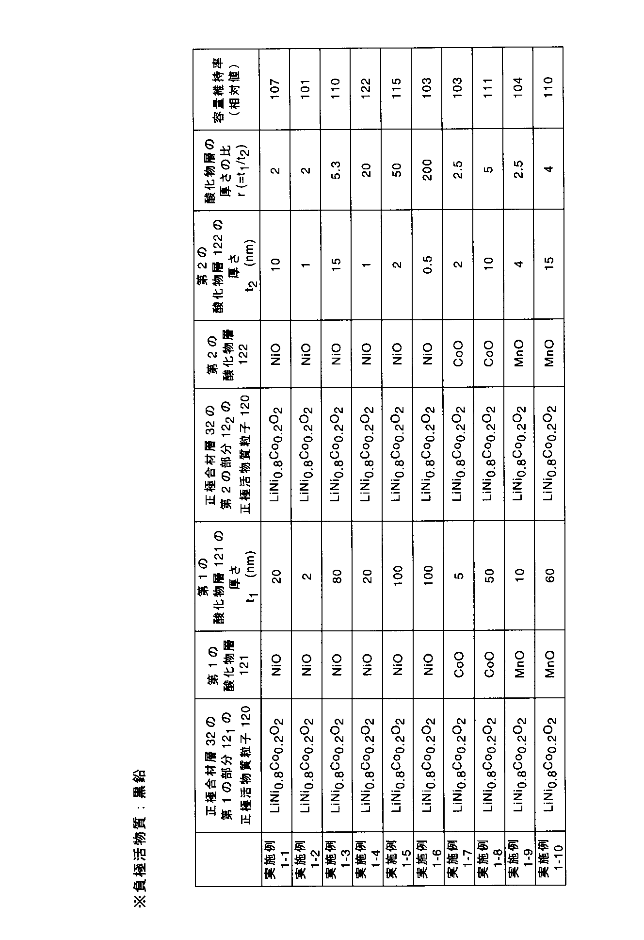

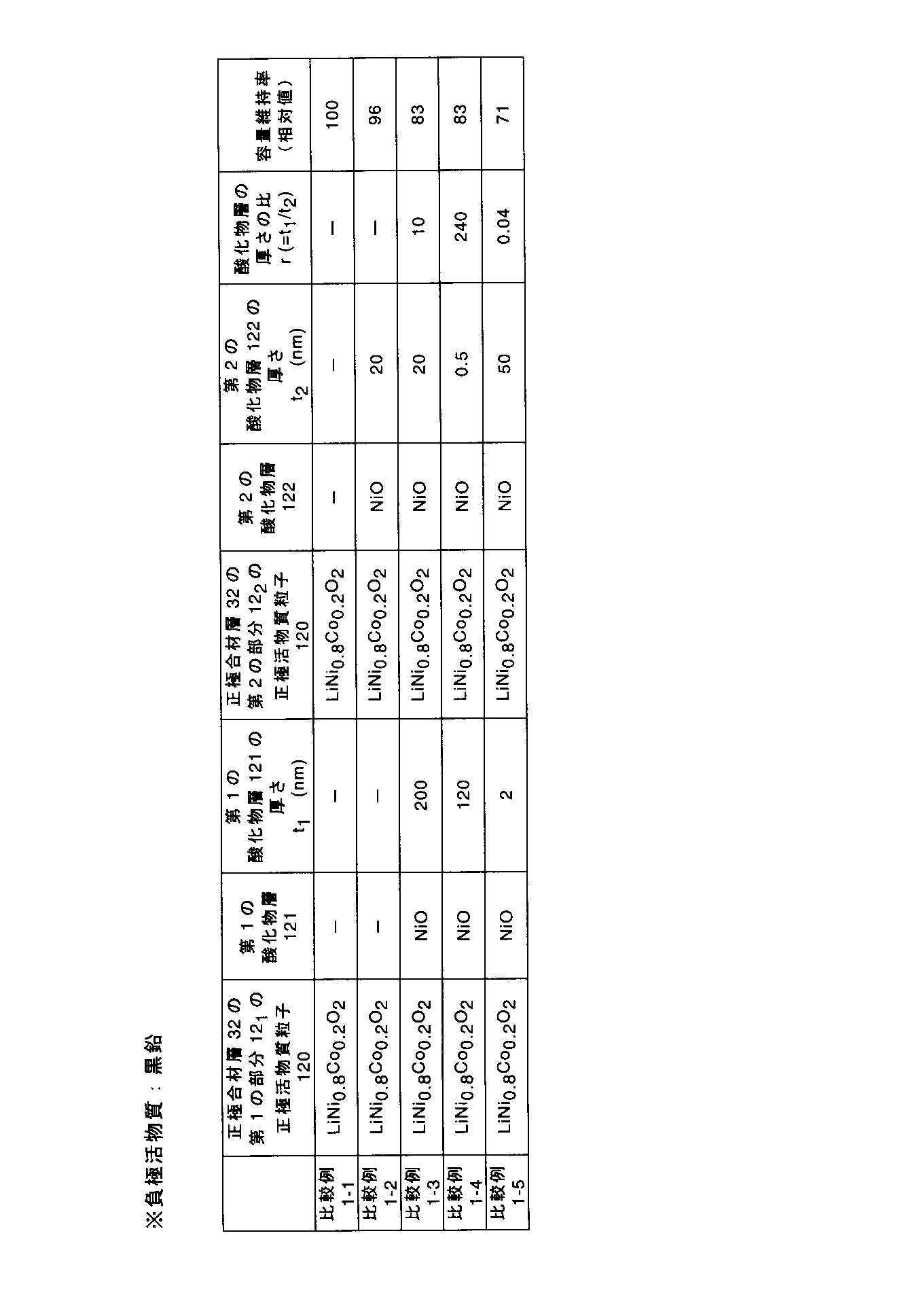
表4~表6の結果から、実施例1-1~実施例1-23の非水電解質電池100は、比較例1-1~比較例1-5の非水電解質電池に比べて、容量維持率に優れていることが分かる。また、表4~表6の結果から、実施例1系列では、第1及び第2の酸化物層の組成が異なっていても、同様の効果が得られたことが分かる。
一方、比較例1-3及び比較例1-4の非水電解質電池は、第1の酸化物層及び第2の酸化物層を含んでいたが、容量維持率が、実施例1-1~実施例1-23の非水電解質電池100よりも劣っており、ましてや比較例1-1及び比較例1-2の非水電解質電池よりも劣っていた。これは、第1の酸化物層の厚さが200nmと大きかったため、第1の酸化物層による抵抗が大きく、その結果、正極合材層の第2の部分の劣化が過度に進行してしまったからであると考えられる。
また、比較例1-5の非水電解質電池は、第1の酸化物層及び第2の酸化物層を含んでいたが、容量維持率が、実施例1-1~実施例1-23の非水電解質電池100よりも劣っており、ましてや比較例1-1~比較例1-4の非水電解質電池よりも劣っていた。これは、第2の酸化物層の厚さが第1の酸化物層の厚さよりも大きかったために、正極合材層の第1の部分と第2の部分との間での正極活物質の劣化の進行のずれを抑制できなかったからであると考えられる。
(実施例2-1~実施例2-4)
実施例2-1~実施例2-4では、正極活物質粒子を以下の表7に示したものに変更したことと、以下の表7に示した厚さt1を有する目的の第1の酸化物層121が得られるように第1のスラリーを調製するための混合溶液の調製条件を先に説明したように変更したことと、以下の表7に示した厚さt2を有する目的の第2の酸化物層122が得られるように第2のスラリーを調製するための混合溶液の調製条件を先に説明したように変更したことと以外は実施例1-1と同様にして、実施例2-1~実施例2-4のそれぞれの非水電解質電池100を作製した。
実施例2-1~実施例2-4では、正極活物質粒子を以下の表7に示したものに変更したことと、以下の表7に示した厚さt1を有する目的の第1の酸化物層121が得られるように第1のスラリーを調製するための混合溶液の調製条件を先に説明したように変更したことと、以下の表7に示した厚さt2を有する目的の第2の酸化物層122が得られるように第2のスラリーを調製するための混合溶液の調製条件を先に説明したように変更したことと以外は実施例1-1と同様にして、実施例2-1~実施例2-4のそれぞれの非水電解質電池100を作製した。
(比較例2-1~比較例2-4)
比較例2-1~比較例2-4では、正極作製のための第1のスラリー及び第2のスラリーの作製の際に、正極活物質複合体粉末に変えて、酸化物層形成処理を施していない正極活物質粒子粉末を用いたこと以外は実施例2-1~実施例2-4のそれぞれと同様にして、比較例2-1~比較例2-4の非水電解質電池を作製した。すなわち、比較例2-1~2-4の非水電解質電池は、第1の酸化物層も第2の酸化物層も含んでいなかった。
比較例2-1~比較例2-4では、正極作製のための第1のスラリー及び第2のスラリーの作製の際に、正極活物質複合体粉末に変えて、酸化物層形成処理を施していない正極活物質粒子粉末を用いたこと以外は実施例2-1~実施例2-4のそれぞれと同様にして、比較例2-1~比較例2-4の非水電解質電池を作製した。すなわち、比較例2-1~2-4の非水電解質電池は、第1の酸化物層も第2の酸化物層も含んでいなかった。
<評価>
実施例2-1~実施例2-4において、第1のスラリー及び第2のスラリーを調製する際に、実施例1-1と同様にして、第1の酸化物層及び第2の酸化物層の同定を行った。その結果を以下の表7に示す。
実施例2-1~実施例2-4において、第1のスラリー及び第2のスラリーを調製する際に、実施例1-1と同様にして、第1の酸化物層及び第2の酸化物層の同定を行った。その結果を以下の表7に示す。
また、実施例2-1~実施例2-4及び比較例2-1~比較例2-4において、正極合材層32の厚さT、正極合材層32の第1の部分121の厚さT1、及び正極合材層32の第2の部分122の厚さT2を、実施例1-1と同様にして測定した。その結果、正極合材層32の厚さT、正極合材層32の第1の部分121の厚さT1、及び正極合材層32の第2の部分122の厚さT2は、実施例1-1のそれらとそれぞれ同じであった。
そして、実施例2-1~実施例2-4の非水電解質電池100及び比較例2-1~比較例2-4の非水電解質電池に対して、実施例1-1の非水電解質電池100に対して行ったのと同様の手順で、容量維持率の測定、並びに第1の酸化物層及び第2の酸化物層の厚さの測定を行った。これらの結果を以下の表7に示す。なお、表7において、実施例2-1~実施例2-4の非水電解質電池100の容量維持率は、それぞれ、比較例2-1~比較例2-4の非水電解質電池のそれらを100とした相対値として示している。
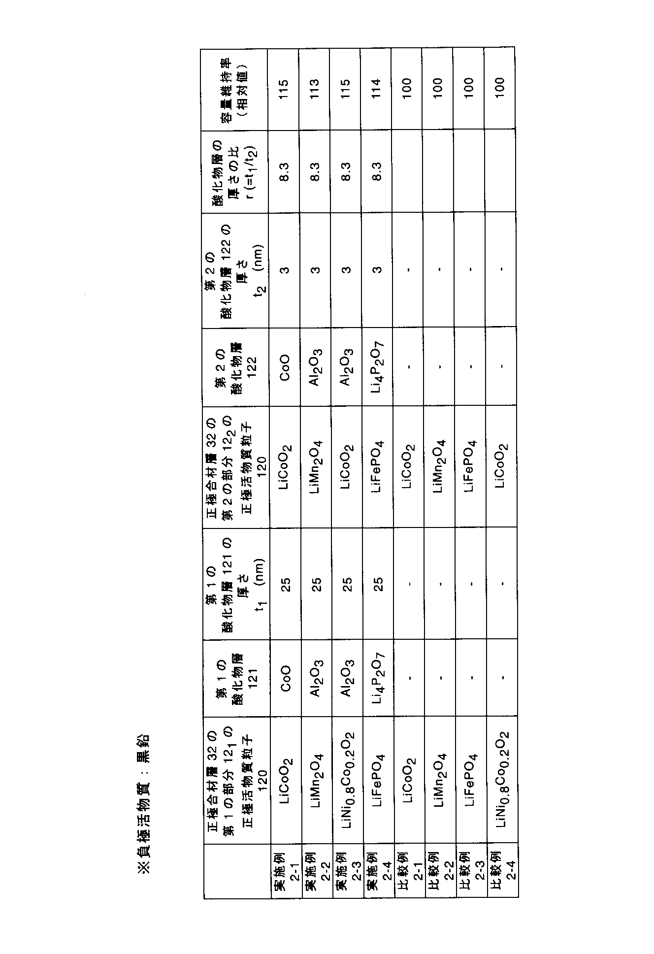
表7の結果から、実施例2-1~実施例2-4の非水電解質電池100の容量維持率は、それぞれ、比較例2-1~比較例2-4の非水電解質電池のそれらよりも優れていることが分かる。また、表7の結果から、実施例2系列の非水電解質電池100は、実施例1系列の非水電解質電池100とは正極活物質粒子が異なっているが、実施例1系列の非水電解質電池100と同様の効果を発揮できたことが分かる。
(実施例3-1~実施例3~23及び比較例3-1~比較例3-5)
実施例3-1~実施例3~23及び比較例3-1~比較例3-5では、負極活物質として、黒鉛粉末に変えて、リチウム吸蔵電位が1.55V(対Li/Li+)であるスピネル型構造のチタン酸リチウム(Li4Ti5O12)粉末を使用したこと以外は実施例1-1~実施例1-23及び比較例1-1~比較例1-5とそれぞれ同様にして、非水電解質電池を作製した。
実施例3-1~実施例3~23及び比較例3-1~比較例3-5では、負極活物質として、黒鉛粉末に変えて、リチウム吸蔵電位が1.55V(対Li/Li+)であるスピネル型構造のチタン酸リチウム(Li4Ti5O12)粉末を使用したこと以外は実施例1-1~実施例1-23及び比較例1-1~比較例1-5とそれぞれ同様にして、非水電解質電池を作製した。
実施例3-1~実施例3~23及び比較例3-1~比較例3-5では、具体的には、以下の手順により負極2を作製した。
負極活物質として、リチウム吸蔵電位が1.55V(対Li/Li+)であるスピネル型構造のチタン酸リチウム(Li4Ti5O12)粉末85重量%と、グラファイト5重量%と、アセチレンブラック3重量%と、PVdF7重量%とを、NMPに加えて混合し、スラリーを調製した。このスラリーを厚さ11μmのアルミニウム箔からなる負極集電体21の両面に塗布し、乾燥し、プレスした。塗布の際、負極集電体21にスラリーを塗布しない部分を残した。かくして、負極集電体21と、その両面に担持された、密度が2.0g/cm3である負極合材層22とを具備する負極2を作製した。
<評価>
実施例3-1~実施例3-23、及び比較例3-1~比較例3-5において、正極合材層32の厚さT、正極合材層32の第1の部分121の厚さT1、及び正極合材層32の第2の部分122の厚さT2を、実施例1-1と同様にして測定した。その結果、これらの例における正極合材層32の厚さT、正極合材層32の第1の部分121の厚さT1、及び正極合材層32の第2の部分122の厚さT2は、実施例1-1のそれらとそれぞれ同じであった。
実施例3-1~実施例3-23、及び比較例3-1~比較例3-5において、正極合材層32の厚さT、正極合材層32の第1の部分121の厚さT1、及び正極合材層32の第2の部分122の厚さT2を、実施例1-1と同様にして測定した。その結果、これらの例における正極合材層32の厚さT、正極合材層32の第1の部分121の厚さT1、及び正極合材層32の第2の部分122の厚さT2は、実施例1-1のそれらとそれぞれ同じであった。
また、実施例3-1~実施例3~23の非水電解質電池100及び比較例3-1~比較例3-5の非水電解質電池に対して、実施例1-1の非水電解質電池100に対して行ったのと同様の手順で、容量維持率の測定、並びに第1の酸化物層及び第2の酸化物層の厚さの測定を行った。これらの結果を以下の表8~表10に示す。なお、表8~表10において、各非水電解質電池の容量維持率は、比較例3-1の非水電解質電池のそれらを100とした相対値として示している。
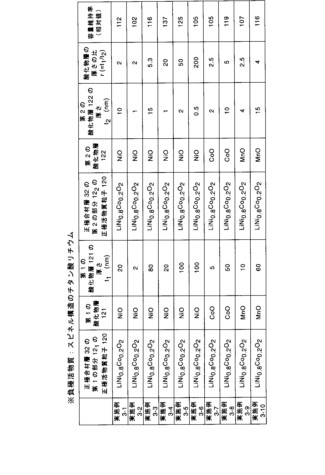

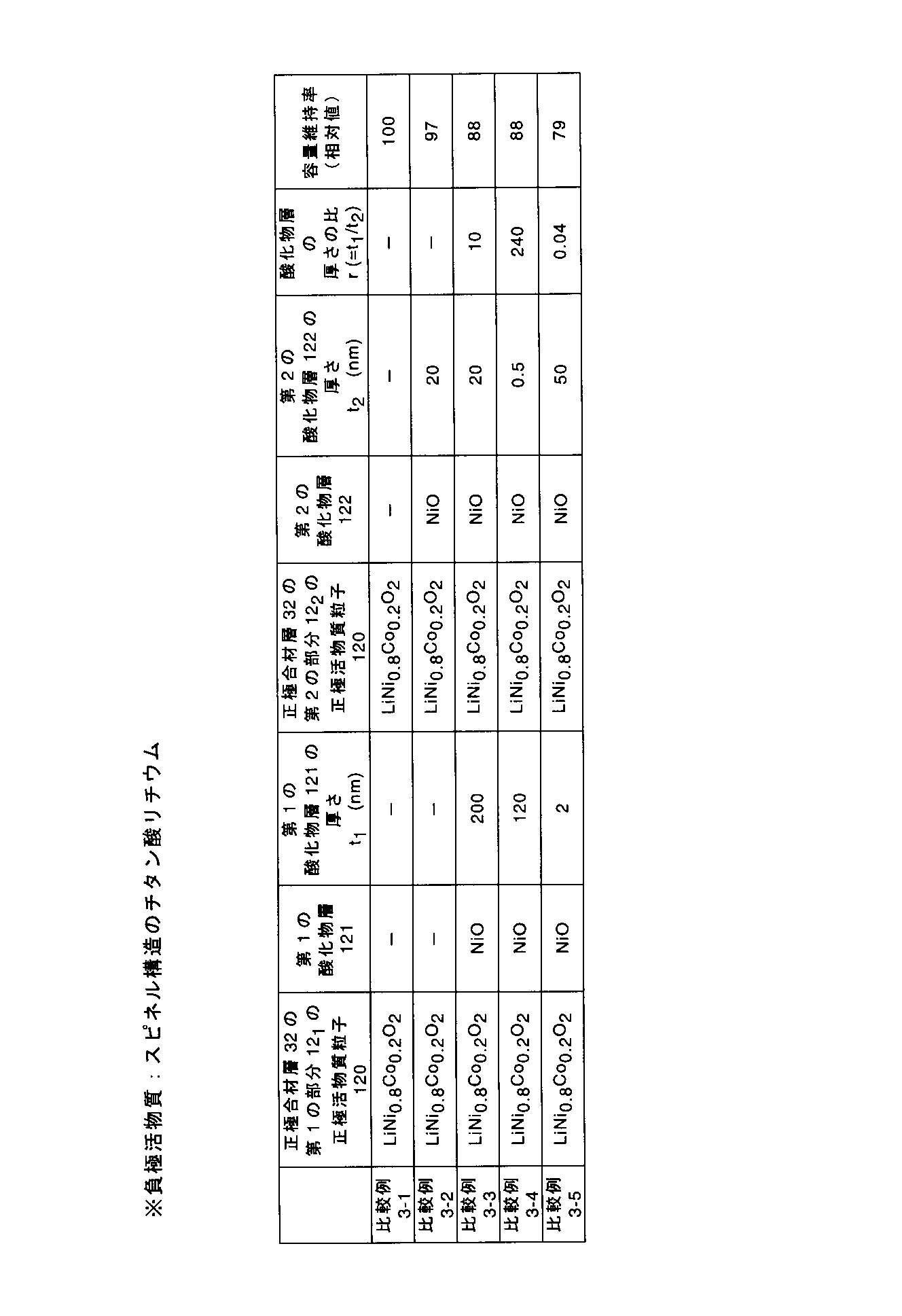
表8~表10の結果から、実施例3-1~実施例3-23の非水電解質電池100は、比較例3-1~比較例3-5の非水電解質電池に比べて、容量維持率に優れていることが分かる。また、表8~表10の結果から、実施例3系列では、第1及び第2の酸化物層の組成が異なっていても、同様の効果を発揮することができたことが分かる。
また、表4~表6に示した実施例1系列の結果と表8~表10に示した実施例3系列の結果を比較すると、負極活物質としてスピネル型構造のチタン酸リチウムを用いた実施例3系列の非水電解質電池100は、負極活物質として黒鉛を用いた実施例1系列の非水電解質電池100よりもより優れた容量維持率を達成することができたことが分かる。
(実施例4-1~実施例4-4及び比較例4-1~比較例4-4)
実施例4-1~実施例4-4及び比較例4-1~比較例4-4では、負極活物質として、黒鉛粉末に変えて、リチウム吸蔵電位が1.55V(対Li/Li+)であるスピネル型構造のチタン酸リチウム(Li4Ti5O12)粉末を使用したこと以外は実施例2-1~実施例2-4及び比較例2-1~比較例2-4とそれぞれ同様にして、実施例4-1~実施例4-4及び比較例4-1~比較例4-4の非水電解質電池を作製した。
実施例4-1~実施例4-4及び比較例4-1~比較例4-4では、負極活物質として、黒鉛粉末に変えて、リチウム吸蔵電位が1.55V(対Li/Li+)であるスピネル型構造のチタン酸リチウム(Li4Ti5O12)粉末を使用したこと以外は実施例2-1~実施例2-4及び比較例2-1~比較例2-4とそれぞれ同様にして、実施例4-1~実施例4-4及び比較例4-1~比較例4-4の非水電解質電池を作製した。
負極活物質としてスピネル型構造のチタン酸リチウムを含む負極2は、実施例3系列で説明したのと同様の手順で作製した。
<評価>
実施例4-1~実施例4-4、及び比較例4-1~比較例4-4において、正極合材層32の厚さT、正極合材層32の第1の部分121の厚さT1、及び正極合材層32の第2の部分122の厚さT2を、実施例1-1と同様にして測定した。その結果、これらの例における正極合材層32の厚さT、正極合材層32の第1の部分121の厚さT1、及び正極合材層32の第2の部分122の厚さT2は、実施例1-1のそれらとそれぞれ同じであった。
実施例4-1~実施例4-4、及び比較例4-1~比較例4-4において、正極合材層32の厚さT、正極合材層32の第1の部分121の厚さT1、及び正極合材層32の第2の部分122の厚さT2を、実施例1-1と同様にして測定した。その結果、これらの例における正極合材層32の厚さT、正極合材層32の第1の部分121の厚さT1、及び正極合材層32の第2の部分122の厚さT2は、実施例1-1のそれらとそれぞれ同じであった。
また、実施例4-1~実施例4-4の非水電解質電池及び比較例4-1~比較例4-4の非水電解質電池に対して、実施例1-1の非水電解質電池に対して行ったのと同様に、容量維持率の測定、並びに第1の酸化物層及び第2の酸化物層の厚さの測定を行った。これらの結果を以下の表11に示す。なお、表11において、実施例4-1~実施例4-4の非水電解質電池100の容量維持率は、それぞれ、比較例4-1~比較例4-4の非水電解質電池100のそれらを100とした相対値として示している。

表11の結果から、実施例4-1~実施例4-4の非水電解質電池100の容量維持率は、それぞれ、比較例4-1~比較例4-4の非水電解質電池のそれらよりも優れていることが分かる。また、表11の結果から、実施例4系列の非水電解質電池100は、実施例3系列の非水電解質電池100とは正極活物質粒子が異なっているが、実施例3系列の非水電解質電池100と同様の効果を発揮できたことが分かる。
また、表7に示した実施例2系列の結果と表11に示した実施例4系列の結果を比較すると、負極活物質としてスピネル型構造のチタン酸リチウムを用いた実施例4系列の非水電解質電池100は、負極活物質として黒鉛を用いた実施例2系列の非水電解質電池100よりもより優れた容量維持率を達成することができたことが分かる。
更に、実施例1-1~1-23、実施例2-1~2-4、実施例3-1~実施例3-23及び実施例4-1~4-4の非水電解質電池は、正極の密度を高くしても、先に説明したように、優れた容量維持率を示すことができた。
すなわち、以上に説明した少なくとも一つの実施形態及び実施例によれば、電極合材層の第1の部分に含まれる活物質粒子の表面に形成された第1の酸化物層の厚さが、電極合材層の第2の部分に含まれる活物質粒子の表面に形成された第2の酸化物層の厚さよりも大きい電極が提供される。この電極は、電極の容量低下を抑えながら、電極合材層における活物質の劣化の偏りを解消することができるので、高いエネルギー密度及び優れた容量維持率を示すことができる非水電解質電池を実現することができる。
本発明のいくつかの実施形態を説明したが、これらの実施形態は、例として提示したものであり、発明の範囲を限定することは意図していない。これら新規な実施形態は、その他の様々な形態で実施されることが可能であり、発明の要旨を逸脱しない範囲で、種々の省略、置き換え、変更を行うことができる。これら実施形態やその変形は、発明の範囲や要旨に含まれるとともに、特許請求の範囲に記載された発明とその均等の範囲に含まれる。
10…電極、11…集電体、12…電極合材層、12a…電極合材層の第1の面、12b…電極合材層の第2の面、121…電極合材層の第1の部分、122…電極合材層の第2の部分、120…活物質粒子、121…第1の酸化物層、122…第2の酸化物層、130…導電剤、140…結着剤、1…電極群、2…負極、21…負極集電体、22…負極合材層、3…正極、31…正極集電体、32…正極合材層、4…セパレータ、5…負極端子、6…正極端子、7…外装袋、100…非水電解質電池。
Claims (5)
- Liと、Fe、Mn、Co及びNiからなる群より選択される少なくとも一種の遷移金属とを含有する活物質粒子を含んだ電極合材層と、
前記電極合材層を少なくとも一方の面に担持した集電体と
を具備し、
前記電極合材層は、前記集電体に接している第1の面と、前記第1の面から前記電極合材層の厚さだけ離れた第2の面とを含み、
前記電極合材層は、
前記電極合材層の前記厚さの少なくとも20%の厚さを有し、前記第1の面を含んだ第1の部分と、
前記電極合材層の前記厚さの少なくとも20%の厚さを有し、前記第2の面を含んだ第2の部分と
を含み、
前記電極合材層の前記第1の部分において、前記活物質粒子の表面には、第1の酸化物層が形成されており、前記第1の酸化物層は、Li、Mg、Ca、B、Al、Si、P、Fe、Mn、Co、Ni、Cu、Zn、Zr、Nb、Mo、Ta及びWからなる群より選択される少なくとも1種の元素を含有し、前記第1の酸化物層の厚さは、0.5nmより大きく且つ100nm以下であり、
前記電極合材層の前記第2の部分において、前記活物質粒子の表面には、第2の酸化物層が形成されており、前記第2の酸化物層は、Li、Mg、Ca、B、Al、Si、P、Fe、Mn、Co、Ni、Cu、Zn、Zr、Nb、Mo、Ta及びWからなる群より選択される少なくとも1種の元素を含有し、前記第2の酸化物層の厚さは、0.5nm以上であり且つ100nmより小さく、
前記第1の酸化物層の前記厚さは、前記第2の酸化物層の前記厚さよりも大きいことを特徴とする電極。 - 前記第1の酸化物層の前記厚さの前記第2の酸化物層の前記厚さに対する比が、5以上であることを特徴とする請求項1に記載の電極。
- 正極としての請求項2に記載の電極と、
負極と、
非水電解質と
を具備することを特徴とする非水電解質電池。 - 前記負極が、リチウムの酸化還元電位よりも1V以上の電位でリチウムの挿入及び脱離反応をすることができる負極活物質を含むことを特徴とする請求項3に記載の非水電解質電池。
- 前記負極活物質がスピネル構造のチタン酸リチウムを含むことを特徴とする請求項4に記載の非水電解質電池。
Priority Applications (4)
| Application Number | Priority Date | Filing Date | Title |
|---|---|---|---|
| EP18186013.1A EP3419086B1 (en) | 2014-01-06 | 2014-12-26 | Electrode and nonaqueous electrolyte battery |
| CN201480072402.0A CN105900266B (zh) | 2014-01-06 | 2014-12-26 | 电极及非水电解质电池 |
| EP14875951.7A EP3093909B1 (en) | 2014-01-06 | 2014-12-26 | Electrode and nonaqueous electrolyte battery |
| US15/196,732 US10003073B2 (en) | 2014-01-06 | 2016-06-29 | Electrode and nonaqueous electrolyte battery |
Applications Claiming Priority (2)
| Application Number | Priority Date | Filing Date | Title |
|---|---|---|---|
| JP2014-000596 | 2014-01-06 | ||
| JP2014000596A JP6251042B2 (ja) | 2014-01-06 | 2014-01-06 | 電極及び非水電解質電池 |
Related Child Applications (1)
| Application Number | Title | Priority Date | Filing Date |
|---|---|---|---|
| US15/196,732 Continuation US10003073B2 (en) | 2014-01-06 | 2016-06-29 | Electrode and nonaqueous electrolyte battery |
Publications (1)
| Publication Number | Publication Date |
|---|---|
| WO2015102091A1 true WO2015102091A1 (ja) | 2015-07-09 |
Family
ID=53493434
Family Applications (1)
| Application Number | Title | Priority Date | Filing Date |
|---|---|---|---|
| PCT/JP2014/084519 Ceased WO2015102091A1 (ja) | 2014-01-06 | 2014-12-26 | 電極及び非水電解質電池 |
Country Status (5)
| Country | Link |
|---|---|
| US (1) | US10003073B2 (ja) |
| EP (2) | EP3419086B1 (ja) |
| JP (1) | JP6251042B2 (ja) |
| CN (2) | CN105900266B (ja) |
| WO (1) | WO2015102091A1 (ja) |
Cited By (1)
| Publication number | Priority date | Publication date | Assignee | Title |
|---|---|---|---|---|
| JP2020102337A (ja) * | 2018-12-21 | 2020-07-02 | 三洋電機株式会社 | 合材層材料の製造方法、二次電池の製造方法、及び二次電池 |
Families Citing this family (10)
| Publication number | Priority date | Publication date | Assignee | Title |
|---|---|---|---|---|
| CN106030872B (zh) * | 2013-11-29 | 2018-12-18 | 株式会社半导体能源研究所 | 锂锰复合氧化物及二次电池 |
| CN105098193A (zh) | 2015-09-24 | 2015-11-25 | 宁德时代新能源科技有限公司 | 正极片以及包括该正极片的锂离子电池 |
| US11430983B2 (en) * | 2017-03-27 | 2022-08-30 | Panasonic Intellectual Property Management Co., Ltd. | Nonaqueous electrolyte secondary battery |
| JP7079411B2 (ja) * | 2018-04-24 | 2022-06-02 | トヨタ自動車株式会社 | 電極とこれを用いた電池 |
| US11121408B2 (en) | 2019-03-14 | 2021-09-14 | Medtronic, Inc. | Lithium-ion battery |
| JP7656831B2 (ja) | 2020-01-31 | 2025-04-04 | パナソニックIpマネジメント株式会社 | 電気化学素子およびその製造方法、ならびに電気化学デバイス |
| EP4099434A4 (en) | 2020-01-31 | 2023-08-23 | Panasonic Intellectual Property Management Co., Ltd. | ELECTROCHEMICAL ELEMENT AS WELL AS METHOD FOR MANUFACTURING THE SAME, AND ELECTROCHEMICAL DEVICE |
| EP4099439A4 (en) * | 2020-01-31 | 2024-03-20 | Panasonic Intellectual Property Management Co., Ltd. | ACTIVE MATERIAL PARTICLES, ELECTROCHEMICAL ELEMENT, METHOD FOR PRODUCING THE ACTIVE MATERIAL PARTICLES, METHOD FOR PRODUCING THE ELECTROCHEMICAL ELEMENT, AND ELECTROCHEMICAL DEVICE |
| JP7674128B2 (ja) * | 2021-03-25 | 2025-05-09 | Tdk株式会社 | リチウムイオン二次電池用正極及びリチウムイオン二次電池 |
| WO2023008089A1 (ja) * | 2021-07-29 | 2023-02-02 | パナソニックIpマネジメント株式会社 | 二次電池用正極およびその製造方法、ならびに二次電池 |
Citations (10)
| Publication number | Priority date | Publication date | Assignee | Title |
|---|---|---|---|---|
| JP2006012433A (ja) | 2004-06-22 | 2006-01-12 | Nichia Chem Ind Ltd | 非水電解質二次電池用正極活物質および非水電解質二次電池 |
| JP2006012426A (ja) | 2004-06-22 | 2006-01-12 | Nichia Chem Ind Ltd | 非水電解質二次電池用正極活物質および非水電解質二次電池 |
| JP2008016244A (ja) | 2006-07-04 | 2008-01-24 | Sony Corp | 正極活物質およびその製造方法、並びに非水電解質二次電池 |
| US20090050859A1 (en) * | 2004-06-14 | 2009-02-26 | Industrial Technology Research Institute | Cathode material particle |
| JP2009200007A (ja) * | 2008-02-25 | 2009-09-03 | Toyota Motor Corp | 多孔性金属酸化物被覆正極活物質の製造方法、およびリチウム二次電池の製造方法 |
| JP2009206047A (ja) * | 2008-02-29 | 2009-09-10 | Hitachi Ltd | リチウム二次電池 |
| JP2009218198A (ja) * | 2008-02-13 | 2009-09-24 | Tdk Corp | 活物質及び電極の製造方法、活物質及び電極 |
| WO2012121220A1 (ja) * | 2011-03-07 | 2012-09-13 | 旭硝子株式会社 | リチウムイオン二次電池用の正極活物質およびその製造方法 |
| JP2013084499A (ja) * | 2011-10-12 | 2013-05-09 | Toyota Motor Corp | 硫化物固体電池システム |
| JP2013543221A (ja) * | 2010-09-30 | 2013-11-28 | エルジー・ケム・リミテッド | リチウム二次電池用正極及びそれを備えたリチウム二次電池 |
Family Cites Families (9)
| Publication number | Priority date | Publication date | Assignee | Title |
|---|---|---|---|---|
| WO2002061864A1 (en) * | 2001-01-31 | 2002-08-08 | Korea Institute Of Science And Technology | A lithium electrode comprising surface-treated lithium particles, its fabrication method and lithium battery comprising the same |
| JP5247989B2 (ja) * | 2006-03-27 | 2013-07-24 | プライムアースEvエナジー株式会社 | 電池 |
| JP2009070781A (ja) * | 2007-09-18 | 2009-04-02 | Fuji Heavy Ind Ltd | 蓄電デバイス |
| CN101978534A (zh) * | 2008-03-24 | 2011-02-16 | 3M创新有限公司 | 高电压阴极组合物 |
| JP5205424B2 (ja) * | 2010-08-06 | 2013-06-05 | 株式会社日立製作所 | リチウム二次電池用正極材料,リチウム二次電池及びそれを用いた二次電池モジュール |
| WO2012049746A1 (ja) * | 2010-10-13 | 2012-04-19 | トヨタ自動車株式会社 | 電極板、二次電池、及び、電極板の製造方法 |
| FR2970376B1 (fr) * | 2011-01-07 | 2013-01-25 | Commissariat Energie Atomique | Materiau d'electrode positive biphase pour accumulateur au lithium et son procede de synthese |
| JP2013048112A (ja) * | 2012-11-22 | 2013-03-07 | Toyota Motor Corp | 正極活物質 |
| CN103199242B (zh) * | 2013-03-05 | 2017-05-03 | 东莞新能源科技有限公司 | 硼硅酸盐包覆改性的钴酸锂及其制备方法 |
-
2014
- 2014-01-06 JP JP2014000596A patent/JP6251042B2/ja active Active
- 2014-12-26 CN CN201480072402.0A patent/CN105900266B/zh active Active
- 2014-12-26 WO PCT/JP2014/084519 patent/WO2015102091A1/ja not_active Ceased
- 2014-12-26 EP EP18186013.1A patent/EP3419086B1/en active Active
- 2014-12-26 EP EP14875951.7A patent/EP3093909B1/en active Active
- 2014-12-26 CN CN201810895174.7A patent/CN109065842B/zh active Active
-
2016
- 2016-06-29 US US15/196,732 patent/US10003073B2/en active Active
Patent Citations (10)
| Publication number | Priority date | Publication date | Assignee | Title |
|---|---|---|---|---|
| US20090050859A1 (en) * | 2004-06-14 | 2009-02-26 | Industrial Technology Research Institute | Cathode material particle |
| JP2006012433A (ja) | 2004-06-22 | 2006-01-12 | Nichia Chem Ind Ltd | 非水電解質二次電池用正極活物質および非水電解質二次電池 |
| JP2006012426A (ja) | 2004-06-22 | 2006-01-12 | Nichia Chem Ind Ltd | 非水電解質二次電池用正極活物質および非水電解質二次電池 |
| JP2008016244A (ja) | 2006-07-04 | 2008-01-24 | Sony Corp | 正極活物質およびその製造方法、並びに非水電解質二次電池 |
| JP2009218198A (ja) * | 2008-02-13 | 2009-09-24 | Tdk Corp | 活物質及び電極の製造方法、活物質及び電極 |
| JP2009200007A (ja) * | 2008-02-25 | 2009-09-03 | Toyota Motor Corp | 多孔性金属酸化物被覆正極活物質の製造方法、およびリチウム二次電池の製造方法 |
| JP2009206047A (ja) * | 2008-02-29 | 2009-09-10 | Hitachi Ltd | リチウム二次電池 |
| JP2013543221A (ja) * | 2010-09-30 | 2013-11-28 | エルジー・ケム・リミテッド | リチウム二次電池用正極及びそれを備えたリチウム二次電池 |
| WO2012121220A1 (ja) * | 2011-03-07 | 2012-09-13 | 旭硝子株式会社 | リチウムイオン二次電池用の正極活物質およびその製造方法 |
| JP2013084499A (ja) * | 2011-10-12 | 2013-05-09 | Toyota Motor Corp | 硫化物固体電池システム |
Cited By (2)
| Publication number | Priority date | Publication date | Assignee | Title |
|---|---|---|---|---|
| JP2020102337A (ja) * | 2018-12-21 | 2020-07-02 | 三洋電機株式会社 | 合材層材料の製造方法、二次電池の製造方法、及び二次電池 |
| JP7138038B2 (ja) | 2018-12-21 | 2022-09-15 | 三洋電機株式会社 | 合材層材料の製造方法、及び二次電池の製造方法 |
Also Published As
| Publication number | Publication date |
|---|---|
| EP3093909A4 (en) | 2017-08-02 |
| US10003073B2 (en) | 2018-06-19 |
| CN109065842A (zh) | 2018-12-21 |
| JP2015130254A (ja) | 2015-07-16 |
| EP3093909A1 (en) | 2016-11-16 |
| CN105900266B (zh) | 2018-09-07 |
| JP6251042B2 (ja) | 2017-12-20 |
| EP3093909B1 (en) | 2018-08-01 |
| EP3419086B1 (en) | 2020-03-25 |
| US20160308202A1 (en) | 2016-10-20 |
| CN105900266A (zh) | 2016-08-24 |
| CN109065842B (zh) | 2021-07-09 |
| EP3419086A1 (en) | 2018-12-26 |
Similar Documents
| Publication | Publication Date | Title |
|---|---|---|
| JP6251042B2 (ja) | 電極及び非水電解質電池 | |
| JP6523115B2 (ja) | 電池用活物質、負極、非水電解質電池、電池パック及び車 | |
| CN101127399B (zh) | 活性物质和电极的制造方法、活性物质和电极 | |
| JP6289995B2 (ja) | 負極、負極の製造方法、及び非水電解質電池 | |
| JP6523892B2 (ja) | 電極、非水電解質電池、電池パック及び車 | |
| JP6092466B2 (ja) | 電池用活物質、非水電解質電池、組電池、電池パック及び自動車 | |
| JP6668478B2 (ja) | 非水電解質電池及び電池パック | |
| JP2014209445A (ja) | 電池用活物質材料、非水電解質電池及び電池パック。 | |
| WO2016136212A1 (ja) | 非水電解質二次電池 | |
| JP6571284B2 (ja) | 電極、非水電解質電池及び電池パック | |
| WO2019193691A1 (ja) | 正極、電極群及び非水電解質電池 | |
| JP6659274B2 (ja) | 非水電解質電池用負極活物質、負極、非水電解質電池、組電池、電池パック及び自動車 | |
| JP2016171023A (ja) | 電池用活物質、非水電解質電池、及び電池パック | |
| JP5168829B2 (ja) | 正極活物質および非水電解質電池 | |
| WO2011089697A1 (ja) | 非水電解質電池、これに用いる正極活物質及びその製造方法 | |
| WO2023079639A1 (ja) | 電極、電池、及び電池パック | |
| JP7615173B2 (ja) | 電極、電池、及び電池パック | |
| JP6746983B2 (ja) | リチウム鉄マンガン系複合活物質構造、それを用いたリチウムイオン二次電池、及び製造方法 | |
| JP6479938B2 (ja) | 非水電解質電池 | |
| JP6965438B2 (ja) | 活物質、電極、非水電解質電池及び電池パック | |
| JPWO2020202350A1 (ja) | 電極、電池及び電池パック | |
| WO2023175731A1 (ja) | 電極、電池、及び電池パック | |
| WO2014155708A1 (ja) | リチウムイオン二次電池用正極材料、リチウムイオン二次電池用正極、及びリチウムイオン二次電池 |
Legal Events
| Date | Code | Title | Description |
|---|---|---|---|
| 121 | Ep: the epo has been informed by wipo that ep was designated in this application |
Ref document number: 14875951 Country of ref document: EP Kind code of ref document: A1 |
|
| REEP | Request for entry into the european phase |
Ref document number: 2014875951 Country of ref document: EP |
|
| WWE | Wipo information: entry into national phase |
Ref document number: 2014875951 Country of ref document: EP |
|
| NENP | Non-entry into the national phase |
Ref country code: DE |