WO2015102115A1 - Dispositif de tomodensitométrie à rayons x, et dispositif de tomodensitométrie par comptage de photons - Google Patents
Dispositif de tomodensitométrie à rayons x, et dispositif de tomodensitométrie par comptage de photons Download PDFInfo
- Publication number
- WO2015102115A1 WO2015102115A1 PCT/JP2015/050148 JP2015050148W WO2015102115A1 WO 2015102115 A1 WO2015102115 A1 WO 2015102115A1 JP 2015050148 W JP2015050148 W JP 2015050148W WO 2015102115 A1 WO2015102115 A1 WO 2015102115A1
- Authority
- WO
- WIPO (PCT)
- Prior art keywords
- ray
- ray source
- rays
- control unit
- ring
- Prior art date
- Legal status (The legal status is an assumption and is not a legal conclusion. Google has not performed a legal analysis and makes no representation as to the accuracy of the status listed.)
- Ceased
Links
Images


Classifications
-
- H—ELECTRICITY
- H05—ELECTRIC TECHNIQUES NOT OTHERWISE PROVIDED FOR
- H05G—X-RAY TECHNIQUE
- H05G1/00—X-ray apparatus involving X-ray tubes; Circuits therefor
- H05G1/08—Electrical details
- H05G1/26—Measuring, controlling or protecting
- H05G1/30—Controlling
- H05G1/32—Supply voltage of the X-ray apparatus or tube
-
- A—HUMAN NECESSITIES
- A61—MEDICAL OR VETERINARY SCIENCE; HYGIENE
- A61B—DIAGNOSIS; SURGERY; IDENTIFICATION
- A61B6/00—Apparatus or devices for radiation diagnosis; Apparatus or devices for radiation diagnosis combined with radiation therapy equipment
- A61B6/02—Arrangements for diagnosis sequentially in different planes; Stereoscopic radiation diagnosis
- A61B6/03—Computed tomography [CT]
- A61B6/032—Transmission computed tomography [CT]
-
- A—HUMAN NECESSITIES
- A61—MEDICAL OR VETERINARY SCIENCE; HYGIENE
- A61B—DIAGNOSIS; SURGERY; IDENTIFICATION
- A61B6/00—Apparatus or devices for radiation diagnosis; Apparatus or devices for radiation diagnosis combined with radiation therapy equipment
- A61B6/06—Diaphragms
-
- A—HUMAN NECESSITIES
- A61—MEDICAL OR VETERINARY SCIENCE; HYGIENE
- A61B—DIAGNOSIS; SURGERY; IDENTIFICATION
- A61B6/00—Apparatus or devices for radiation diagnosis; Apparatus or devices for radiation diagnosis combined with radiation therapy equipment
- A61B6/40—Arrangements for generating radiation specially adapted for radiation diagnosis
- A61B6/4007—Arrangements for generating radiation specially adapted for radiation diagnosis characterised by using a plurality of source units
-
- A—HUMAN NECESSITIES
- A61—MEDICAL OR VETERINARY SCIENCE; HYGIENE
- A61B—DIAGNOSIS; SURGERY; IDENTIFICATION
- A61B6/00—Apparatus or devices for radiation diagnosis; Apparatus or devices for radiation diagnosis combined with radiation therapy equipment
- A61B6/40—Arrangements for generating radiation specially adapted for radiation diagnosis
- A61B6/4035—Arrangements for generating radiation specially adapted for radiation diagnosis the source being combined with a filter or grating
-
- A—HUMAN NECESSITIES
- A61—MEDICAL OR VETERINARY SCIENCE; HYGIENE
- A61B—DIAGNOSIS; SURGERY; IDENTIFICATION
- A61B6/00—Apparatus or devices for radiation diagnosis; Apparatus or devices for radiation diagnosis combined with radiation therapy equipment
- A61B6/42—Arrangements for detecting radiation specially adapted for radiation diagnosis
- A61B6/4266—Arrangements for detecting radiation specially adapted for radiation diagnosis characterised by using a plurality of detector units
-
- A—HUMAN NECESSITIES
- A61—MEDICAL OR VETERINARY SCIENCE; HYGIENE
- A61B—DIAGNOSIS; SURGERY; IDENTIFICATION
- A61B6/00—Apparatus or devices for radiation diagnosis; Apparatus or devices for radiation diagnosis combined with radiation therapy equipment
- A61B6/44—Constructional features of apparatus for radiation diagnosis
-
- A—HUMAN NECESSITIES
- A61—MEDICAL OR VETERINARY SCIENCE; HYGIENE
- A61B—DIAGNOSIS; SURGERY; IDENTIFICATION
- A61B6/00—Apparatus or devices for radiation diagnosis; Apparatus or devices for radiation diagnosis combined with radiation therapy equipment
- A61B6/48—Diagnostic techniques
- A61B6/482—Diagnostic techniques involving multiple energy imaging
-
- A—HUMAN NECESSITIES
- A61—MEDICAL OR VETERINARY SCIENCE; HYGIENE
- A61B—DIAGNOSIS; SURGERY; IDENTIFICATION
- A61B6/00—Apparatus or devices for radiation diagnosis; Apparatus or devices for radiation diagnosis combined with radiation therapy equipment
- A61B6/52—Devices using data or image processing specially adapted for radiation diagnosis
- A61B6/5205—Devices using data or image processing specially adapted for radiation diagnosis involving processing of raw data to produce diagnostic data
-
- A—HUMAN NECESSITIES
- A61—MEDICAL OR VETERINARY SCIENCE; HYGIENE
- A61B—DIAGNOSIS; SURGERY; IDENTIFICATION
- A61B6/00—Apparatus or devices for radiation diagnosis; Apparatus or devices for radiation diagnosis combined with radiation therapy equipment
- A61B6/54—Control of apparatus or devices for radiation diagnosis
-
- A—HUMAN NECESSITIES
- A61—MEDICAL OR VETERINARY SCIENCE; HYGIENE
- A61B—DIAGNOSIS; SURGERY; IDENTIFICATION
- A61B6/00—Apparatus or devices for radiation diagnosis; Apparatus or devices for radiation diagnosis combined with radiation therapy equipment
- A61B6/56—Details of data transmission or power supply, e.g. use of slip rings
-
- H—ELECTRICITY
- H01—ELECTRIC ELEMENTS
- H01J—ELECTRIC DISCHARGE TUBES OR DISCHARGE LAMPS
- H01J35/00—X-ray tubes
- H01J35/02—Details
- H01J35/04—Electrodes ; Mutual position thereof; Constructional adaptations therefor
- H01J35/06—Cathodes
- H01J35/065—Field emission, photo emission or secondary emission cathodes
-
- A—HUMAN NECESSITIES
- A61—MEDICAL OR VETERINARY SCIENCE; HYGIENE
- A61B—DIAGNOSIS; SURGERY; IDENTIFICATION
- A61B6/00—Apparatus or devices for radiation diagnosis; Apparatus or devices for radiation diagnosis combined with radiation therapy equipment
- A61B6/02—Arrangements for diagnosis sequentially in different planes; Stereoscopic radiation diagnosis
- A61B6/03—Computed tomography [CT]
- A61B6/032—Transmission computed tomography [CT]
- A61B6/035—Mechanical aspects of CT
-
- A—HUMAN NECESSITIES
- A61—MEDICAL OR VETERINARY SCIENCE; HYGIENE
- A61B—DIAGNOSIS; SURGERY; IDENTIFICATION
- A61B6/00—Apparatus or devices for radiation diagnosis; Apparatus or devices for radiation diagnosis combined with radiation therapy equipment
- A61B6/42—Arrangements for detecting radiation specially adapted for radiation diagnosis
- A61B6/4208—Arrangements for detecting radiation specially adapted for radiation diagnosis characterised by using a particular type of detector
- A61B6/4241—Arrangements for detecting radiation specially adapted for radiation diagnosis characterised by using a particular type of detector using energy resolving detectors, e.g. photon counting
-
- A—HUMAN NECESSITIES
- A61—MEDICAL OR VETERINARY SCIENCE; HYGIENE
- A61B—DIAGNOSIS; SURGERY; IDENTIFICATION
- A61B6/00—Apparatus or devices for radiation diagnosis; Apparatus or devices for radiation diagnosis combined with radiation therapy equipment
- A61B6/44—Constructional features of apparatus for radiation diagnosis
- A61B6/4488—Means for cooling
-
- A—HUMAN NECESSITIES
- A61—MEDICAL OR VETERINARY SCIENCE; HYGIENE
- A61B—DIAGNOSIS; SURGERY; IDENTIFICATION
- A61B6/00—Apparatus or devices for radiation diagnosis; Apparatus or devices for radiation diagnosis combined with radiation therapy equipment
- A61B6/50—Apparatus or devices for radiation diagnosis; Apparatus or devices for radiation diagnosis combined with radiation therapy equipment specially adapted for specific body parts; specially adapted for specific clinical applications
- A61B6/503—Apparatus or devices for radiation diagnosis; Apparatus or devices for radiation diagnosis combined with radiation therapy equipment specially adapted for specific body parts; specially adapted for specific clinical applications for diagnosis of the heart
-
- H—ELECTRICITY
- H01—ELECTRIC ELEMENTS
- H01J—ELECTRIC DISCHARGE TUBES OR DISCHARGE LAMPS
- H01J2235/00—X-ray tubes
- H01J2235/06—Cathode assembly
- H01J2235/062—Cold cathodes
-
- H—ELECTRICITY
- H01—ELECTRIC ELEMENTS
- H01J—ELECTRIC DISCHARGE TUBES OR DISCHARGE LAMPS
- H01J2235/00—X-ray tubes
- H01J2235/06—Cathode assembly
- H01J2235/068—Multi-cathode assembly
-
- H—ELECTRICITY
- H01—ELECTRIC ELEMENTS
- H01J—ELECTRIC DISCHARGE TUBES OR DISCHARGE LAMPS
- H01J35/00—X-ray tubes
- H01J35/02—Details
- H01J35/04—Electrodes ; Mutual position thereof; Constructional adaptations therefor
- H01J35/045—Electrodes for controlling the current of the cathode ray, e.g. control grids
Definitions
- the present embodiment relates to an X-ray computed tomography apparatus and a photon counting CT apparatus.
- raw data is collected by rotating a rotating ring equipped with one or more sets of X-ray tubes and X-ray detectors.
- the rotation speed of the rotating ring reaches 0.275 s / rot at the shortest.
- the centrifugal force due to rotation is proportional to mass and proportional to the square of angular velocity. For this reason, it is difficult to significantly reduce the rotational speed of the rotating ring from the current level.
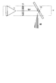
- an electron beam is emitted from the back of the gantry using an electron gun, the electron trajectory is deflected using a coil, and is incident on anodes arranged on the circumference to generate X-rays. .
- CT is realized by deflecting the electron beam on the circumference.
- the scanning time is determined by the scanning time of the electron beam.
- the scan time for the fifth generation CT is 50-100 ms.
- Patent Document 1 proposes a method in which a detector-side collimator (post-collimator) is attached to a gantry and only the post-collimator is rotated in the fifth generation CT. Further, Patent Document 1 shows a fifth generation CT that can also cope with spectral CT by changing the applied voltage for each location.
- this method uses an electron gun, the size of the entire system becomes large, and the X-ray detector and the electron beam are in an offset positional relationship. It is unsuitable.
- An object of the embodiment is to provide an X-ray computed tomography apparatus and a photon counting CT apparatus capable of performing high-speed imaging.
- the X-ray computed tomography apparatus includes two X-ray source rings arranged along a central axis, and each of the two X-ray source rings includes a plurality of circles arranged on a circumference.
- Two X-ray source rings having an X-ray source, and a single detector ring provided between the two X-ray source rings and having a plurality of X-ray detectors arranged on the circumference.
- Each of the plurality of X-ray detectors detects X-rays from the two X-ray source rings, the detector ring, and data collection for collecting digital data according to the detected X-ray intensity.
- a reconstruction unit that reconstructs a CT image based on the digital data.
- FIG. 7 is a longitudinal sectional view showing the detailed structure of the X-ray source ring of FIG.
- positioning in the time t + (DELTA) of an X-ray source, a wedge filter, and a back collimator in case 1 simultaneous X-ray source drive number is 1 concerning 1st Embodiment.
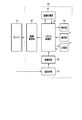
- FIG. 1 is a diagram illustrating functional blocks of the X-ray computed tomography apparatus according to the first embodiment.
- the X-ray computed tomography apparatus according to the first embodiment includes a gantry 10 and a console 50.
- the gantry 10 is installed in a CT imaging room, for example.
- the console 50 is installed in an imaging control room adjacent to the CT imaging room, for example.
- the gantry 10 and the console 50 are connected so as to communicate with each other via a network or the like.
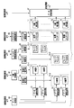
- FIG. 2 is a diagram showing functional blocks of the gantry 10.
- FIG. 3 is a diagram schematically showing the structure of the gantry 10.
- the gantry 10 accommodates two annular structures (hereinafter referred to as X-ray source rings) 13 that accommodate a plurality of X-ray sources 11 and a plurality of X-ray detectors 15.
- a single annular structure (hereinafter referred to as a detector ring) 17 is included.
- a detector ring 17 is disposed between the X-ray source ring 13-1 and the X-ray source ring 13-2.
- the X-ray source ring 13-1, the X-ray source ring 13-2, and the detector ring 17 are arranged along the central axis Z so that the central axes Z spatially coincide with each other. ing.
- the X-ray source ring 13-1, the X-ray source ring 13-2, and the detector ring 17 share an aperture.
- the inside of the opening is set to FOV (field of view).
- a top plate 19 supported by a bed (not shown) is inserted into the opening.
- a subject S is placed on the top 19.
- the top plate 19 is positioned so that the imaging region of the subject S is included in the FOV.
- the two X-ray source rings 13-1 and 13-2 are not distinguished from each other, they are collectively referred to as the X-ray source ring 13.
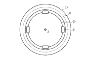
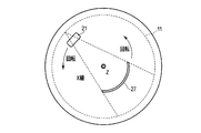
- FIG. 4 is a schematic cross-sectional view of the X-ray source ring 13.
- the structures of the X-ray source ring 13-1 and the X-ray source ring 13-2 are substantially the same.
- the X-ray source ring 13 has a plurality of X-ray sources 11 arranged in a circumferential shape.
- a plurality of X-ray sources 11 may be arranged along the central axis Z.
- Each of the plurality of X-ray sources 11 generates X-rays.
- a cold cathode X-ray tube is used as the X-ray source 11.
- the inside of the X-ray source ring 13 is kept in a vacuum. That is, the X-ray source ring 13 functions as a vacuum container. As a result, all the X-ray sources 11 are placed in a vacuum.
- a plurality of wedge filters 21 are arranged on the inner peripheral side outside the X-ray source ring 13.
- the plurality of wedge filters 21 are rotatably supported around the central axis Z by, for example, an annular support (hereinafter referred to as a filter support) 23.
- the filter support 23 is individually provided for each X-ray source ring 13.
- the X-ray source ring 13-1 is provided with a filter support 23-1
- the X-ray source ring 13-2 is provided with a filter support 23-2.
- the wedge filter 21 is an X-ray attenuation filter for making the X-ray dose irradiated to the subject S from each X-ray source 11 spatially uniform. Any number of wedge filters 21 may be provided as long as it is one or more. More specifically, the wedge filters 21 are provided by the number of simultaneous X-ray irradiation directions of the X-ray source 11. In the case of FIG. 4, the number of installed wedge filters 21 is four.
- the filter support 23-1 is connected to the filter drive unit 25-1, and the filter support 23-2 is connected to the filter drive unit 25-2.
- the number of X-ray simultaneous irradiation directions is set to be the same for the X-ray source ring 13-1 and the X-ray source ring 13-2.
- the filter support 23 when the two filter supports 23-1 and the filter support 23-2 are not distinguished from each other, they are collectively referred to as the filter support 23, and the two filter driving units 25-1 and 25 are combined.
- -2 is collectively referred to as the filter driving unit 25 when not distinguished from -2.
- the filter drive unit 25-1 and the filter drive unit 25-2 are connected to the filter drive control unit 63. Each of the filter drive unit 25-1 and the filter drive unit 25-2 generates power in accordance with control by the filter drive control unit 63.
- the filter support 23 receiving the power rotates around the central axis Z at a constant angular velocity.
- the filter support 23 rotates independently of the X-ray source ring 13. That is, the X-ray source ring 13 remains stationary even when the filter support 23 rotates.
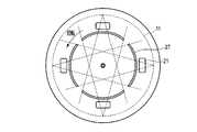
- FIG. 5 is a schematic cross-sectional view of the detector ring 17.
- the detector ring 17 has a plurality of X-ray detectors 15 arranged on the circumference.
- Each X-ray detector 15 detects X-rays from the X-ray source ring 13 and generates an electrical signal corresponding to the detected X-ray intensity.
- the X-ray detector 15 may be a direct detection type semiconductor detector or an indirect type detector composed of a scintillator and a photodetector.
- a plurality of collimators (hereinafter referred to as post-collimators) 27 are arranged on the inner peripheral side outside the detector ring 17.
- the post-collimator 27 is a structure made of an X-ray attenuation material for limiting the solid angle of incident X-rays to the X-ray detector 15.
- a collimator having the same structure as that of the current third generation CT may be provided.
- the plurality of post-collimators 27 are supported so as to be rotatable around the central axis Z by, for example, an annular support (hereinafter referred to as a collimator support) 29. Any number of post-collimators 27 may be installed as long as it is one or more.
- the number of post-collimators 27 is the same as the number of wedge filters 21, that is, the number of simultaneous irradiation directions of the X-ray source 11.
- an angle around the central axis Z is referred to as an azimuth angle.
- 0 degree corresponds to the highest position of the X-ray source ring 13 or the detector ring 17
- 180 degrees corresponds to the lowest position of the X-ray source ring 13 or the detector ring 17.
- the number of simultaneous irradiation directions is the number of X-ray bundles that are simultaneously irradiated and have different azimuth angles.
- the number of post-collimators 27 is four.
- the collimator support 29 is connected to the collimator driving unit 31.
- the collimator drive unit 31 generates power according to the control by the collimator drive control unit 65.
- the collimator support 29 receiving the power rotates around the central axis Z at a constant angular velocity.
- the collimator support 29 rotates independently of the detector ring 17. That is, even if the collimator support 29 rotates, the detector ring 17 remains stationary.
- FIG. 6 is a diagram schematically showing the structure of the X-ray source 11. As shown in FIG. 6, a plurality of X-ray sources 11 are mounted on the X-ray source ring 13.
- the X-ray source 11 includes a cold cathode electron source 111, a gate electrode 113, and an anode 115.
- the cold cathode electron source 111 is a substance that emits electrons using a field emission phenomenon.
- the field emission phenomenon is a phenomenon in which electrons in a metal placed in a high electric field exceed the work function and are emitted to the outside.
- a material hereinafter referred to as a field emission material used for the cold cathode electron source 111, silicon or carbon nanotube is suitable.
- the field emission material is processed to have a sharp tip, and a plurality of cold cathode electron sources 111 are formed.
- the plurality of cold cathode electron sources 111 are mounted on, for example, a semiconductor substrate.
- the plurality of cold cathode electron sources 111 are arranged so as to make one round around the central axis Z in the X-ray source ring 13.
- a plurality of gate electrodes 113 are arranged in front of the plurality of cold cathode electron sources 111.
- the gate electrode 113 is an electrode for generating an electric field with the cold cathode electron source 111.
- a gate drive circuit 33 is connected to the gate electrode 113.
- the gate drive circuit 33 applies a gate pulse to the gate electrode 113 according to control by the gate control unit 59.
- the gate electrode 113 that has received the application of the gate pulse generates an electric field with the cold cathode electron source 111.
- the cold cathode electron source 111 in an electric field emits electrons from the tip due to a field emission phenomenon.
- the plurality of gate electrodes 113 are mounted on a semiconductor substrate.
- the plurality of gate electrodes 113 are arranged so as to make one round around the central axis Z in the X-ray source ring 13.
- an anode 115 is disposed at a position facing the cold cathode electron source 111 with the gate electrode 113 interposed therebetween.
- the anode 115 is disposed so as to face the cold cathode electron source 111.
- the plurality of anodes 115 are mounted by a semiconductor substrate.
- the plurality of anodes 115 are arranged so as to make one round around the central axis Z in the X-ray source ring 13.
- the anode 115 receives electrons from the cold cathode electron source 111 and generates X-rays.
- the anode 115 and the cold cathode electron source 111 are connected to the high voltage generator 35.
- a high voltage generator 35 is provided for each X-ray source ring 13. Specifically, a high voltage generator 35-1 is connected to the X-ray source ring 13-1, and a high voltage generator 35-2 is connected to the X-ray source ring 13-2.
- the high voltage generator 35 applies a tube voltage between the anode 115 and the cold cathode electron source 111 according to the control from the X-ray control unit 61.
- the electrons emitted from the cold cathode electron source 111 receive a tube voltage, fly toward the anode 115, and collide with the anode 115.
- X-rays are generated by the collision of electrons with the anode 115.
- the generated X-rays are irradiated to the opposite side of the cold cathode electron source 111 with the gate electrode 113 interposed therebetween.
- X-rays emitted from the X-ray source 11 fly toward the X-ray detector 15 located on the opposite side of the X-ray source 11 with the central axis Z interposed therebetween, and are detected by the X-ray detector 15.
- the cold cathode electron source 111 and the anode 115 are positioned so that the generated X-rays are directed to the X-ray detector 15 located on the opposite side of the X-ray source 11.
- the X-ray source 11 and a plurality of X-ray sources 11 mounted on the X-ray source ring 13-2 are positioned.
- a spatial region where the X-rays emitted from the X-ray source ring 13-1 and the X-rays emitted from the X-ray source ring 13-2 overlap is set as the FOV.
- the configuration of the X-ray source 11 in FIG. 6 is merely an example.
- the anode 115 is arranged so as to face the electron flow, that is, the target transmission type.
- this embodiment is not limited to this.
- the anode 115 may be disposed obliquely with respect to the electron flow, that is, a target reflection type.
- the cold cathode electron source 111 and the anode 115 are positioned so that the generated X-rays are directed to the X-ray detector 15 located on the opposite side of the X-ray source 11.
- each X-ray source 11 is provided with one cold cathode electron source 111, one gate electrode 113, and one anode 115.
- this embodiment is not limited to this.
- the number of cold cathode electron sources 111, gate electrodes 113, and anodes 115 included in each X-ray source 11 can be increased or decreased individually.
- one anode 115 may be provided for a plurality of cold cathode electron sources 111, or a plurality of anodes 115 may be provided for one cold cathode electron source 111.
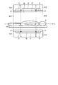
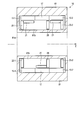
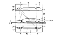
- FIG. 8 is a longitudinal sectional view of the gantry 10 according to the present embodiment.
- the gantry 10 has a housing 81 in which an opening 81a is formed.
- An X-ray source ring 13-1, a detector ring 17, and an X-ray source ring 13-2 are arranged in order along the central axis Z in the internal space 81b of the casing 81.
- a filter support 23-1 that supports at least one wedge filter 21 is disposed on the inner peripheral side of the X-ray source ring 13-1.
- a filter support 23-2 that supports at least one wedge filter 21 is disposed on the inner peripheral side of the X-ray source ring 13-2.
- Each filter support 23 has an opening having a diameter larger than that of the opening 81a, and is disposed in the internal space 81b so that the central axis thereof coincides with the axis Z.
- Each filter support 23 is preferably disposed on the opposite side of the X-ray detection ring 17 with respect to the central axis Z so as not to block X-rays from each X-ray source ring 13.
- a collimator support 29 that supports at least one post-collimator 27 is disposed on the inner peripheral side of the detector ring 17.
- the collimator support 29 has an opening having a diameter larger than that of the opening 81a, and is disposed in the internal space 81b so that the central axis thereof coincides with the axis Z.
- the filter support 23 and the collimator support 29 are rotated about the central axis Z by a filter drive unit 25 and a collimator drive unit 31 (not shown in FIG. 7), respectively.
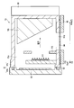
- FIG. 9 is a longitudinal sectional view showing the detailed structure of each X-ray source ring 13.
- a direction along the central axis Z of each X-ray source ring 13 is referred to as a column direction (Row direction), and a circumferential direction of the X-ray source ring 13 is referred to as a channel direction (Ch direction).
- the orthogonal direction between the column direction and the channel direction coincides with the radial direction (Ra direction) of the X-ray source ring 13.
- the X-ray source ring 13 includes a casing 91 having a ring shape with the central axis Z as the central axis.
- the housing 91 has a hollow structure, and the internal space 91a of the housing 91 is kept in a vacuum. More specifically, the housing 91 includes a lid 91b having a ring shape with the axis Z as a central axis and a container 91c.
- the lid 91b and the container 91c are preferably formed of a robust material such as iron or stainless steel.
- the lid 91b and the container 91c are preferably fastened by a fastener or the like so as to keep the vacuum in the internal space 91a with high accuracy. For example, the lid 91b and the container 91c are fastened through a gasket 92.
- any existing type such as a non-metallic gasket, a semi-metallic gasket, or a metal gasket may be used.
- a getter 93 that adsorbs the residual gas in the internal space 91a is provided on the inner surface of the lid 91b.
- the getter 93 either a contact getter or a diffusion getter may be used.
- any existing metal such as titanium or barium / aluminum alloy may be used.
- a plurality of cold cathode electron sources 111 are provided on the X-ray detection ring 17 side of the X-ray source ring 13.
- the plurality of cold cathode electron sources 111 are arranged along the channel direction and the radial direction.
- the plurality of cold cathode electron sources 111 are fixed to the support 111a, and the support 111a is fixed to the inner surface of the container 91c.
- An anode 115 is provided on the opposite side of the plurality of cold cathode electron sources 111 in the column direction.
- a plurality of anodes 115 may be arranged along the channel direction, or an anode 115 having a ring shape with the axis Z as a central axis may be provided.
- the anode 115 irradiates the X-ray detection ring 17 adjacent along the central axis Z with an X-ray, the anode 115 is inclined so that the thickness in the column direction decreases as it goes to the central axis Z along the radial direction. Yes. That is, the inclination directions of the anode 115 and the X-ray source ring 13-2 included in the X-ray source ring 13-1 are designed symmetrically with respect to the X-ray detection ring 17.
- a gate electrode 113 is provided between the anode 115 and the plurality of cold cathode electron sources 111 in the column direction.
- the plurality of gate electrodes 113 are arranged along the channel direction. For example, when X-rays are radiated from 1000 directions around the central axis Z, only 1000 gate electrodes 113 are preferably provided around the central axis Z.
- One gate electrode 113 is provided for a predetermined number of cold cathode electron sources 111 adjacent in the channel direction. The predetermined number may be any number of 1 or more.
- the gate electrode 113 is fixed to the inner surface of the container 91c, for example.
- an exit port 91d for X-rays generated from the anode 115 is formed in the container 91c so as to go around the central axis Z.
- An X-ray filter 94 is attached to the outer wall of the container 91c so as to cover the emission port 91d.
- the X-ray filter 94 absorbs low energy components of X-rays that have passed through the exit port 91d.
- a slit 95 is provided on the outer wall of the container 91c via an X-ray filter 94.
- the slit 95 limits the X-ray irradiation field.
- the slit 95 may be provided so as to be rotatable around the central axis Z in synchronization with the wedge filter 21.
- a cooling unit 96 for cooling the X-ray source ring 13 is provided on the outer wall of the container 91c.
- the cooling unit 96 may be any device, instrument, or substance as long as the X-ray source ring 13 can be cooled.
- a cooling pipe through which a refrigerant passes can be applied as the cooling unit 96.
- the main heat source of the X-ray source ring 13 is an anode 115 that generates heat upon receiving electrons from the cold cathode electron source 111. Therefore, the cooling unit 96 is preferably provided on the opposite side of the anode 115 with the container 91c interposed therebetween in order to cool the anode 115 efficiently.
- a data collection circuit 37 is connected to the plurality of X-ray detectors 15.
- the data acquisition circuit 37 reads the electrical signals generated by the plurality of X-ray detectors 15 according to control from the imaging control unit 67, and converts the read electrical signals into digital data by A / D conversion. Specifically, the data acquisition circuit 37 reads an electrical signal from the X-ray detector 15 for each view and converts it into digital data. The converted digital data is called raw data. The raw data is supplied to the console 50. The view corresponds to a sampling period of raw data from each X-ray detector 15 by the data acquisition circuit 37.
- the gate controller 59 is controlled by the imaging controller 67, and includes a plurality of X-ray sources 11 accommodated in the X-ray source ring 13-1 and a plurality of X-ray sources 11 accommodated in the X-ray source ring 13-2. Are individually controlled to generate X-rays according to a preset order. Specifically, the gate control unit 59 supplies timing pulses to the gate drive circuit 33 connected to the X-ray source 11 that is the target of X-ray generation. The gate drive circuit 33 that has received the timing pulse immediately applies the gate pulse to the gate electrode 113 of the connected X-ray source 11. By applying the gate pulse, as described above, electrons are emitted from the cold cathode electron source 111 by the field emission phenomenon, and X-rays are generated by the collision of the electrons with the anode 115.
- the generation order of the X-rays from the X-ray source 11 switching of the X-ray source 11 as an X-ray generation target
- the X-ray source ring 13-1 X-rays are alternately generated from the X-ray source ring 13-2.
- the switching of the plurality of X-ray sources 11 in each X-ray source ring 13 is as follows.
- the X-ray source 11 to be X-ray generated is switched for each view from a plurality of X-ray sources 11 accommodated in each X-ray source ring 13 according to a preset order.
- the X-ray source 11 as an X-ray generation target is switched in order for each view along the circumference.
- the plurality of gate drive circuits 33 are controlled by the gate control unit 59 so that the plurality of X-ray sources 11 generate X-rays in order around the circumference of the X-ray source ring 13.
- X-ray source located at substantially the same irradiation angle among the plurality of X-ray sources 11 accommodated in the X-ray source ring 13-1 and the plurality of X-ray sources 11 accommodated in the X-ray source ring 13-2
- the X-ray generation target is switched between the X-ray source 11 accommodated in the ring 13-1 and the X-ray source 11 accommodated in the X-ray source ring 13-2. With such switching control, X-rays are generated alternately from the two X-ray source rings 13, and X-rays are sequentially generated around the circumference of each of the two X-ray source rings 13.
- the gate drive circuit 33 may be driven so that one X-ray source 11 generates X-rays per view, or X-rays are generated simultaneously from a plurality of X-ray sources 11 per view.
- the gate drive circuit 33 may be driven.
- the plurality of gate drive circuits 33 may be driven so that X-rays are simultaneously generated for each view from four X-ray sources 11 that are spaced apart from each other at equal intervals.
- the X-ray control unit 61 is controlled by the imaging control unit 67 so that a tube voltage corresponding to a predetermined X-ray condition is applied between the cold cathode electron source 111 and the anode 115. And the high voltage generator 35-2 are individually controlled. Specifically, the X-ray control unit 61 increases the tube voltage so that the tube voltage is applied to the X-ray source 11 in synchronization with the application of the gate pulse to the gate electrode 113 of the X-ray source 11 that is the X-ray generation target. A timing pulse is supplied to the voltage generator 35.
- the high voltage generator 35 that has received the timing pulse immediately applies a tube voltage between the cold cathode electron source 111 and the anode 115 of the X-ray source 11 to be X-ray generated.
- a tube voltage By applying the tube voltage, electrons generated from the cold cathode electron source 111 collide with the anode 115 and X-rays are generated.
- the tube voltage application target is not limited to the X-ray source 11 as an X-ray generation target. That is, a tube voltage may be applied to the X-ray source 11 that does not generate X-rays.
- the X-ray condition for the X-ray source ring 13-1 and the X-ray condition for the X-ray source ring 13-2 are typically assumed to be substantially the same.
- the filter drive control unit 63 controls the filter drive unit 25-1 so that the plurality of wedge filters 21 supported by the filter support 23-1 rotate around the central axis Z under the control of the imaging control unit 67,
- the filter driving unit 25-2 is controlled so that the plurality of wedge filters 21 supported by the filter support 23-2 rotate around the central axis Z.
- the filter drive control unit 63 synchronizes with the application of the gate pulse to the gate electrode 113 of the X-ray source 11 that is the target of X-ray generation, in other words, generation of X-rays from the X-ray source 11.
- the driving pulse is supplied to the filter driving unit 25 in synchronization with the above.
- the filter drive unit 25 that has received the drive pulse drives the filter support 23 so that the plurality of wedge filters 21 rotate around the central axis Z at an angular velocity corresponding to the pulse interval of the drive pulse, for example.
- the filter support 23 is rotated so that the wedge filter 21 is always installed on the front surface of the X-ray source 11 to be switched for each view regardless of the switching of the X-ray source 11.
- the filter support 23 is rotated so that the wedge filter 21 is positioned in front of the X-ray generation location in the X-ray source ring 13.
- the filter support 23 may be rotated continuously or intermittently so as to stop when X-rays are generated.
- the collimator drive control unit 65 controls the collimator drive unit 31 so that the plurality of post-collimators 27 rotate around the central axis Z under the control of the imaging control unit 67. Specifically, the collimator drive control unit 65 synchronizes with the application of the gate pulse to the gate electrode 113 of the X-ray source 11 that is the X-ray generation target, in other words, the generation of X-rays from the X-ray source 11. The driving pulse is supplied to the collimator driving unit 31 in synchronization with the above.
- the collimator driving unit 31 that has received the drive pulse drives the collimator support 29 so that the plurality of rear collimators 27 rotate around the central axis Z at an angular velocity corresponding to the pulse interval of the drive pulse, for example. More specifically, the X-ray detector 15 positioned on the opposite side across the central axis Z of the X-ray generation target 11 that is switched for each view is always in front of the X-ray source 11 regardless of switching. The collimator support 29 is rotated so that the post-collimator 27 is installed.
- the collimator support 29 so that the rear collimator 27 is positioned on the front surface of the X-ray detector 15 located on the opposite side of the center axis Z with respect to the X-ray generation location in the X-ray source ring 13. Is rotated.
- the collimator support 29 may be rotated continuously, or may be rotated intermittently so as to stop when X-rays are generated.
- the console 50 has a system control unit 51 as a center, a preprocessing unit 53, a reconstruction unit 55, an image processing unit 57, an imaging control unit 67, a display unit 69, an operation unit 71, and a storage unit. 73.
- the preprocessing unit 53 performs preprocessing on the raw data from the data collection circuit 37.
- the same processing as that used in the third generation CT is used as the preprocessing.
- the preprocessing includes logarithmic conversion, X-ray intensity correction, offset correction, and the like.
- the reconstruction unit 55 applies an image reconstruction algorithm to the preprocessed raw data to generate a CT image representing the spatial distribution of CT values.
- Image reconstruction algorithms include analytical image reconstruction methods such as the FBP (filtered back projection) method and the CBP (convolution back projection) method, the ML-EM (maximum-likelihood-expectation-maximization) method, and the OS-EM (ordered-subset)
- An existing image reconstruction algorithm such as a statistical image reconstruction method such as an expectation (maximization) method may be used.
- the image processing unit 57 performs various image processing on the CT image.
- the image processing unit 57 includes volume rendering, surface rendering, pixel value projection processing, pixel value conversion, and the like.
- the imaging control unit 67 synchronously controls the gate control unit 59, the X-ray control unit 61, the filter drive control unit 63, the collimator drive control unit 65, and the data collection circuit 37. Specifically, the imaging control unit 67 issues a command synchronously to the gate control unit 59 and the X-ray control unit 61 so as to switch the X-ray source 11 that is the X-ray generation target in synchronization with the view switching.
- the imaging control unit 67 includes a wedge filter 21 installed on the front surface of the X-ray source 11 that is an X-ray generation target, and the X-ray detector 15 located on the opposite side of the central axis Z of the X-ray source 11.
- Commands are issued synchronously to the filter drive control unit 63 and the collimator drive control unit 65 so that the rear collimator 27 is installed on the front surface.
- the imaging control unit 67 is configured such that the wedge filter 21 is located in front of the X-ray generation location in the X-ray source ring 13 and is located on the opposite side across the central axis Z of the X-ray generation location. Commands are issued synchronously to the filter drive control unit 63 and the collimator drive control unit 65 so that the post-collimator 27 is positioned in front of the line detector 15.
- the imaging control unit 67 controls the data acquisition circuit 37 so as to read out an electrical signal from the X-ray detector 15 in synchronization with the view switching.
- the view switching timing may be defined by the timing at which a trigger signal is generated from the filter support 23 or the collimator support 29 every time the filter support 23 or the collimator support 29 rotates by a certain angle.
- 67 (or the system control unit 51) may be defined by the generation timing of the divided signal of the clock signal of the clock circuit included in the clock circuit.
- the display unit 69 displays various information on the display device.
- the display unit 69 displays a CT image generated by the reconstruction unit 55, a CT image after image processing by the image processing unit 57, and the like.
- the display unit 69 displays an imaging condition setting screen and the like.
- a CRT display, a liquid crystal display, an organic EL display, a plasma display, or the like can be used as appropriate.
- the operation unit 71 receives various commands and information input from the user by the input device.
- an input device a keyboard, a mouse, various switches, and the like can be used.
- the storage unit 73 is a storage device that stores various types of information.
- the storage unit 73 stores raw data and CT images.
- the storage unit 73 stores an imaging program according to the present embodiment.
- the system control unit 51 functions as the center of the X-ray computed tomography apparatus.
- the system control unit 51 reads the imaging program according to the present embodiment from the storage unit, and controls various components according to the imaging program. Thereby, an imaging process according to the present embodiment is performed.
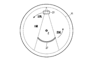
- FIGS. 10A and 10B are plan views showing the arrangement of the X-ray source 11, the wedge filter 21, and the post-collimator 27 of each X-ray source ring 13 when the number of simultaneous irradiation directions is 1.
- FIG. FIG. 10A shows the arrangement at time t
- FIG. 10B shows the arrangement at time t + ⁇ t.
- the imaging control unit 67 switches the X-ray generation target X-ray source 11 around the central axis Z in order, the wedge filter 21 is disposed in front of the X-ray generation target X-ray source 11, and the X-ray generation target A gate controller 59, an X-ray controller 61, a filter drive controller 63, a collimator drive controller 65, and a collimator drive controller 65 so that the rear collimator 27 is disposed on the front surface of the X-ray detector 15 facing the X-ray source 11.
- the data collection circuit 37 is controlled synchronously. At this time, the plurality of X-ray sources 11 and the plurality of X-ray detectors 15 are fixed without being rotated.
- the X-ray generation target X-ray source 11 follows the circumference for each predetermined number of views so that X-rays are exposed from the entire angle range necessary for image reconstruction during the imaging period. Can be switched in order. For example, when performing 360-degree reconstruction, the X-ray generation target X-ray source is electrically connected in order along the circumference for each predetermined number of views so that X-rays are emitted from all directions during the imaging period. Can be switched to.
- the wedge filter 21 and the post-collimator 27 are disposed on the front surface of the X-ray source 11 that is the target of X-ray generation over the imaging period, and on the front surface of the X-ray detector 15 facing the X-ray source 11. It rotates in synchronization with switching of the X-ray source 11 so that the post-collimator 27 is arranged.
- the electrical signal generated by the X-ray detector 15 is collected as raw data by the data collection circuit 37.
- the data acquisition circuit 37 indicates a digital value (hereinafter referred to as an intensity value) corresponding to the intensity of the X-ray for each address (a combination of channel and column) of the X-ray detector that detected the X-ray.
- Collect data hereinafter referred to as intensity value records.
- the data collection circuit 37 generates a set of intensity value records for all addresses related to the same azimuth as raw data. In this way, when the raw data in the angle range necessary for image reconstruction is collected, the imaging control unit 67 ends the imaging.
- the preprocessing unit 53 performs preprocessing on the raw data
- the reconstruction unit 55 generates a CT image based on the raw data after the preprocessing.
- the generated CT image is displayed by the display unit 69.
- the X-ray generation location is arranged along the circumference by electrical switching (switching) with respect to the gate electrode 113.
- switching By moving the X-ray computed tomography apparatus including the X-ray source ring 13 and the detector ring 17, CT imaging similar to the third generation CT can be performed. Switching of the gate electrode 113 by the gate controller 59 is performed at high speed. Therefore, the X-ray computed tomography apparatus according to the present embodiment can shorten the imaging time as compared with the third generation CT that rotates a heavy rotating ring as in the prior art.
- the X-ray computed tomography apparatus rotates the wedge filter 21 and the post-collimator 27 in synchronization with the switching of the X-ray source 11, so that the subject S is similar to the third generation CT. It is possible to reduce the dose of exposure to radiation and to reduce the amount of scattered radiation detected.
- the filter support 23 equipped with the wedge filter 21 and the collimator support 29 equipped with the post-collimator 27 are the third generation CT equipped with an X-ray tube, a high voltage generator, an X-ray detector and the like. It is lightweight compared to the weight of the rotating ring.
- the centrifugal force associated with the rotation of the filter support 23 and the collimator support 29 is lower than the centrifugal force associated with the rotation of the rotation ring of the third generation CT, and the X-ray computed tomography apparatus according to the present embodiment.
- the filter support 23 and the collimator support 29 can be rotated at a high speed at a speed corresponding to the switching speed of the gate electrode 113.
- FIGS. 11A and 11B are diagrams illustrating the arrangement of the X-ray source 11, the wedge filter 21, and the post-collimator 27 in each X-ray source ring 13 when the number of simultaneous irradiation directions is four.
- FIG. 11A shows the arrangement at time t
- FIG. 11B shows the arrangement at time t + ⁇ t.
- a combination of the X-ray source 11, the wedge filter 21, and the post-collimator 27 forms one X-ray irradiation system of CT.
- the number of simultaneous irradiation directions is 4, it is synonymous with the provision of four X-ray irradiation systems.
- the four X-ray sources 11 that are X-ray generation targets are set so as to be separated from each other by 90 degrees in each view.
- the imaging control unit 67 switches the four X-ray sources 11 that are X-ray generation targets in order along the circumference, and the wedge filter 21 is disposed on the front surface of each of the four X-ray sources 11. 11, the gate control unit 59, the X-ray control unit 61, the filter drive control unit 63, and the collimator so that the rear collimator 27 is disposed on the front surface of the X-ray detector 15 located on the opposite side across the central axis Z.
- the drive control unit 65 and the data collection circuit 37 are controlled synchronously. At this time, the plurality of X-ray sources 11 and the plurality of X-ray detectors 15 are fixed without being rotated.
- the X-ray generation target X-ray source 11 is sequentially switched around the circumference every predetermined number of views so that the X-rays are exposed from the entire angle range necessary for image reconstruction. For example, when performing 360-degree reconstruction, the X-ray generation target X-ray source 11 is sequentially changed around the circumference for each predetermined number of views so that X-rays are emitted from all directions during the imaging period. .
- the predetermined number of views can be set to an arbitrary number of one view or more.
- the four wedge filters 21 and the four post-collimators 27 are arranged such that four wedge filters 21 are arranged in front of the four X-ray sources 11 that are X-ray generation targets over the imaging period, respectively.
- the materials of all the wedge filters 21 and the post-collimators 27 are made the same, and the tube voltages to all the X-ray sources 11 are made the same, so that the number of simultaneous irradiation directions is 1.
- the imaging time can be reduced to 1 ⁇ 4.
- the wedge filter 21 and the post-collimator 27 are rotated at the same rotation speed as the current third generation CT, the imaging time can be shortened to 70 ms or less. As a result, the heart CT can be executed without medication even for the subject S having a heart rate of 100 or more.
- the X-ray computed tomography apparatus can significantly reduce the weight of the rotating part as compared with the third generation CT, the wedge is generated with the same centrifugal force as the current third generation CT.
- the filter 21 and the post-collimator 27 are rotated, high-speed imaging of 50 ms or less can be realized.
- the electrical signal generated by the X-ray detector 15 is collected as raw data by the data collection circuit 37.
- the data collection circuit 37 collects an intensity value record indicating a digital value (intensity value) corresponding to the intensity of the X-ray for each address of the X-ray detector 15 that detected the X-ray. Then, the data collection circuit 37 generates a set of intensity value records for all addresses related to the same azimuth as raw data. In this way, when the raw data in the angle range necessary for image reconstruction is collected, the imaging control unit 67 ends the imaging.
- the preprocessing unit 53 performs preprocessing on the raw data, and the reconstruction unit 55 generates a CT image based on the raw data after the preprocessing.
- the generated CT image is displayed by the display unit 69.
- FIGS. 12A and 12B are diagrams schematically showing the X-ray generation timing in the imaging processing using the two X-ray source rings 13.
- FIG. 12A shows X-ray generation in view n
- FIG. 12B shows X-ray generation in view n + 1. Note that n is an integer.
- 12A and 12B the number of X-ray simultaneous irradiation directions is assumed to be 1 for simplicity of explanation. However, even when two X-ray source rings 13 are used, the number of X-ray simultaneous irradiation directions is as follows. Can be set to an arbitrary number of 2 or more. As shown in FIG.
- X-rays are generated from the X-ray source 11 located at the azimuth angle of the X-ray source ring 13-1 in the view n.
- FIG. 12B X-rays are generated from the X-ray source 11 located at the same azimuth angle of the X-ray source ring 13-2 in the view n + 1.
- X-rays are generated from the X-ray source 11.
- the X-ray from the X-ray source ring 13-1 and the subsequent X-ray from the X-ray source ring 13-2 have the same angle around the central axis Z, but the inclination angle from the central axis Z (more details) Are different in the angle of the center line of the X-ray with respect to the axis Z (hereinafter simply referred to as an inclination angle).
- the imaging control unit 67 controls the gate control unit 59 and the X-ray control unit 61 synchronously, and the X-ray source ring 13-1 and the X-ray source ring 13-2 are the X-ray source 11 that is an X-ray generation target. X-rays are alternately generated from the X-ray source ring 13-1 and the X-ray source ring 13-2 while switching in order along the circumferential direction.
- the X-ray generation of the X-ray source 11 and the X-ray source ring 13-2 of the X-ray source ring 13-1 is generated in the view n and the subsequent view n + 1. It is assumed that the target X-ray source 11 is located at the same azimuth angle. However, this embodiment is not limited to this.
- the X-ray source 11 of the X-ray source ring 13-1 and the X-ray source 11 of the X-ray source ring 13-2 are different from each other in the view n and the subsequent view n + 1. It may be located at an azimuth angle.
- the generation order of X-rays in each X-ray source ring 13 can be set to an arbitrary generation order individually by the user.
- the electrical signal generated by the X-ray detector 15 is collected as raw data by the data collection circuit 37.
- the data acquisition circuit 37 has data (intensity value) indicating a digital value (intensity value) corresponding to the intensity of the X-ray for each address (combination of channel and column) of the X-ray detector 15 that detected the X-ray. Value record).
- the data collection circuit 37 generates a set of intensity value records for all addresses as raw data for each combination of azimuth angle and inclination angle.
- the view is switched by the imaging control unit 67 for each combination of the azimuth angle and the tilt angle. In this way, when the raw data in the angle range necessary for image reconstruction is collected, the imaging control unit 67 ends the imaging.
- the preprocessing unit 53 performs preprocessing on the raw data
- the reconstruction unit 55 generates a CT image based on the raw data after the preprocessing. More specifically, the reconstruction unit 55 is based on both raw data derived from X-rays from the X-ray source ring 13-1 and raw data derived from X-rays from the X-ray source ring 13-2. , The CT image for the FOV is reconstructed. The generated CT image is displayed by the display unit 69.
- X-rays are generated alternately from the X-ray source ring 13-1 and the X-ray source ring 13-2.
- this embodiment is not limited to this.
- X-rays may be simultaneously generated from the X-ray source ring 13-1 and the X-ray source ring 13-2.
- FIG. 13 is another diagram schematically showing the X-ray generation timing in the imaging processing using the two X-ray source rings 13.
- X-rays may be generated simultaneously from the X-ray source ring 13-1 and the X-ray source ring 13-2.
- the frequency with which scattered X-rays are generated increases.
- the image quality deteriorates due to scattered X-rays.
- the orientation of the X-ray source 11 of the X-ray source ring 13-1 and the X-ray source 11 of the X-ray source ring 13-2 The angular difference is preferably set to at least 90 degrees or more.
- the X-ray source 11 and the X-ray source ring 13-2 of the X-ray source ring 13-1 are the X-ray generation targets.
- the azimuth angle difference from the X-ray source 11 that is the target of X-ray generation is preferably set to 180 degrees.
- the azimuth angle difference can be arbitrarily set via the operation unit 71.
- the imaging control unit 67 controls the gate control unit 59 and the X-ray control unit 61 synchronously, and maintains the set azimuth angle difference while the X-ray generation target X-ray source of the X-ray source ring 13-1 is maintained.
- 11 and the X-ray source 11 of the X-ray source ring 13-2 are sequentially switched around the circumference, and the X-ray source ring 13-1 and the X-ray source ring 13-2 simultaneously Is generated.
- the imaging time can be shortened.
- X-rays are alternately irradiated from the X-ray source ring 13-1 and the X-ray source ring 13-2
- X-rays are simultaneously irradiated from the X-ray source ring 13-1 and the X-ray source ring 13-2
- the frequency of generation of scattered X-rays can be reduced, that is, the image quality can be improved.
- the mode for simultaneously irradiating X-rays from the X-ray source ring 13-1 and the X-ray source ring 13-2 and the mode for alternately irradiating X-rays are arbitrarily determined in consideration of the balance between imaging time and image quality. It can be set.
- the imaging control unit 67 controls the gate control unit 59 and the X-ray control unit 61 synchronously, and the X-ray source ring 13-1 and the X-ray source ring 13-2.
- X-rays are generated by sequentially switching the azimuth angle around each circle, and X-rays are alternately generated from the X-ray source ring 13-1 and the X-ray source ring 13-2 for each azimuth angle. In this manner, by alternately generating X-rays from different tilt angles at the same imaging angle, it becomes possible to realize a flying-focus scan in a pseudo manner.
- imaging according to the present application using two X-ray source rings 13 increases the number of rays per unit space of X-rays at each imaging angle. As a result, the spatial resolution in the central axis Z direction can be improved. Therefore, the imaging control unit 67 according to the present embodiment can improve the spatial resolution of the CT image as compared with the case where a single X-ray source ring is used.
- the gate control unit 59, the X-ray control unit 61, the filter drive control unit 63, and the collimator drive control unit 65 are provided in the gantry 10, but the present embodiment is not limited to this. That is, some or all of the gate control unit 59, the X-ray control unit 61, the filter drive control unit 63, and the collimator drive control unit 65 may be provided in the console 50.
- the single energy CT is executed even when the number of simultaneous irradiation directions is plural.
- this embodiment is not limited to this.
- the X-ray computed tomography apparatus according to the application example of the present embodiment can execute spectral CT (multi-energy CT) when the number of simultaneous irradiation directions is plural.
- spectral CT multi-energy CT
- the X-ray computed tomography apparatus can execute tube voltage-based spectral CT and filter-based spectral CT for each of the two X-ray source rings 13.
- the X-ray computed tomography apparatus according to this embodiment executes spectral CT individually using two X-ray source rings 13.
- the tube voltage-based spectral CT will be described.
- the X-ray computed tomography apparatus according to the present embodiment can perform spectral CT without limitation on the number of simultaneous irradiation directions. However, in order to describe this embodiment specifically, it is assumed that the number of X-ray source simultaneous irradiation directions is three. Since the execution of the spectral CT is the same in the two X-ray source rings 13, the execution of the spectral CT in one of the X-ray source rings 13 will be described below unless otherwise specified.
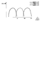
- FIG. 14 is a diagram schematically showing an energy spectrum of X-rays generated from the X-ray source 11 in response to application of different tube voltages.
- the vertical axis in FIG. 14 is defined by the count number of incident X-rays to the X-ray detector 15, and the horizontal axis in FIG. 14 is defined by photon energy.
- the solid line in FIG. 14 shows the energy spectrum of X-rays generated from the X-ray source 11 in response to the application of the low tube voltage, and shows the energy distribution that maximizes the energy value VL corresponding to the low tube voltage value. .
- 14 shows the energy spectrum of X-rays generated from the X-ray source 11 in response to the application of the intermediate tube voltage, and the energy distribution that maximizes the energy value VM corresponding to the intermediate tube voltage value.
- 14 shows an energy spectrum of X-rays generated from the X-ray source 11 in response to application of a high tube voltage, and shows an energy distribution that maximizes an energy value VH corresponding to the high tube voltage value.
- the value of a tube voltage shall become high in order of a low tube voltage, a middle tube voltage, and a high tube voltage.
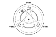
- FIGS. 15A and 15B are plan views showing the arrangement of the X-ray source 11, the wedge filter 21, and the post-collimator 27 when the number of simultaneous irradiation directions is 3 in the tube voltage-based spectral CT.
- FIG. 15A shows the arrangement at time t
- FIG. 15B shows the arrangement at time t + ⁇ t.
- the three wedge filters 21 are supported by the filter support 23 at equal intervals along the circumference
- the three post-collimators 27 are supported by the collimator support 29.
- the three wedge filters 21 are formed of the same material in order to make the X-ray attenuation effect of the filters 21 the same for the X-rays from the three X-ray sources 11.
- the imaging control unit 67 sequentially switches the three X-ray sources 11 to be X-ray generated along the circumference for each of the two X-ray source rings 13.
- a wedge filter 21 is disposed in front of each of the three X-ray sources 11 to be X-ray generated, and is arranged in front of the X-ray detector 15 located on the opposite side of the X-ray source 11 to be X-ray generated with the central axis Z in between.
- the gate control unit 59, the filter drive control unit 63, the collimator drive control unit 65, and the data collection circuit 37 are controlled synchronously so that the post-collimator 27 is arranged.
- the imaging control unit 67 exposes the same angle range necessary for image reconstruction with X-rays at each of the three tube voltages.
- the X-ray control unit 61 are controlled.
- X-rays are irradiated over 360 degrees for each of the two X-ray source rings 13 starting from different angles at the three tube voltages.
- low tube voltage X-rays are exposed in an angle range of 0 to 360 degrees
- medium tube voltage X-rays are exposed in an angle range of 120 to 480 degrees
- high tube voltage X-rays are irradiated.
- the line is exposed in the angular range of 240 to 600 degrees.
- the data collection circuit 37 collects raw data from each X-ray detector 15 for each view.
- the raw data resulting from the X-rays generated from the X-ray source 11 upon receiving the high tube voltage is referred to as high tube voltage raw data, and is generated from the X-ray source upon receiving the intermediate tube voltage.
- Raw data resulting from X-rays is referred to as middle tube voltage raw data, and raw data resulting from X-rays generated from the X-ray source 11 upon application of a low tube high voltage is referred to as low tube voltage raw data.
- the reconstruction unit 55 reconstructs a CT image (high tube voltage CT image) based on the high tube voltage raw data, reconstructs a CT image (medium tube voltage CT image) based on the middle tube voltage raw data, And a CT image (low tube voltage CT image) is reconstructed based on the low tube voltage raw data.
- the reconstruction unit 55 is configured to generate an image (reference material image) relating to a predetermined reference material based on the high tube voltage raw data, the middle tube voltage raw data, and the low tube voltage raw data, and a monochromatic X-ray based on the reference material.
- An image, a density image, or an effective atomic number image may be generated.
- a high tube voltage CT image, a middle tube voltage CT image, a low tube voltage CT image, a reference material image, a monochromatic X-ray image, a density image, and an effective atomic number image are displayed on the display unit 69.
- the spectral CT based on the tube voltage is realized individually for the two X-ray source rings 13. .
- FIG. 16 is a diagram schematically showing an energy spectrum of X-rays generated from the X-ray source 11 and transmitted through the wedge filter 21 having different X-ray attenuation coefficients.
- the vertical axis in FIG. 16 is defined by the number of X-rays incident on the X-ray detector 15, and the horizontal axis in FIG. 16 is defined by photon energy.
- the solid line in FIG. 16 shows the energy spectrum of the generated X-rays that have passed through the wedge filter 21 with a high X-ray attenuation coefficient, and shows the energy distribution that maximizes the energy value VL.
- the dotted line indicates the energy spectrum of the X-ray transmitted through the wedge filter 21 having the medium X-ray attenuation coefficient
- the one-dot chain line indicates the wedge filter 21 having the high X-ray attenuation coefficient.
- transmitted and the energy distribution which maximizes the said energy value VH is shown.
- FIGS. 17A and 17B are plan views showing the arrangement of the X-ray source 11, the wedge filter 21, and the post-collimator when the number of simultaneous irradiation directions is 3 in the filter-based spectral CT.
- FIG. 17A shows the arrangement at time t
- FIG. 17B shows the arrangement at time t + ⁇ t.
- the three wedge filters 21 are supported by the filter support 23 at equal intervals along the circumference
- the three post-collimators 27 are supported by the collimator support 29.
- the three wedge filters 21 are formed of different materials in order to make the X-ray attenuation effect of the filters 21 different from the X-rays from the three X-ray sources 11.
- each wedge filter 21 may be formed of any metal having a different X-ray attenuation coefficient.
- the first wedge filter may be formed of copper
- the second wedge filter may be formed of iodine
- the third wedge filter may be formed of gadolinium.
- the data acquisition circuit 37 collects raw data from each X-ray detector 15 for each view.
- the raw data resulting from the X-rays transmitted through the low X-ray attenuation coefficient wedge filter 21 is referred to as high energy raw data
- the raw data resulting from the X-rays transmitted through the medium X-ray attenuation coefficient wedge filter 21 is referred to as raw data.
- the raw data resulting from the X-rays transmitted through the high X-ray attenuation coefficient wedge filter 21 will be referred to as low-energy raw data.
- the reconstruction unit 55 reconstructs a CT image (high energy CT image) based on the high energy raw data, reconstructs a CT image (medium energy CT image) based on the medium energy raw data, and low energy raw data.
- a CT image (low energy CT image) is reconstructed based on the data.
- the high energy CT image is substantially equivalent to the high tube voltage CT image
- the medium energy CT image is substantially equivalent to the medium tube voltage CT image
- the low energy CT image is substantially equivalent to the low tube voltage CT image. It is equivalent.
- the reconstruction unit 55 performs an image (reference material image) on a predetermined reference material based on the high energy CT raw data, medium energy raw data, and low energy raw data, a monochromatic X-ray image based on the reference material, A density image or an effective atomic number image may be generated.
- a high energy CT image, a medium energy CT image, a low energy CT image, a reference material image, a monochromatic X-ray image, a density image, and an effective atomic number image are displayed on the display unit 69.
- the spectral CT based on the filter is individually realized for the two X-ray source rings 13.
- the spectral CT is executed by individually adjusting the tube voltage and the material of the wedge filter.
- this embodiment is not limited to this. That is, the spectral CT may be executed by optimizing both the tube voltage and the material of the wedge filter.
- the X-ray energy range of each X-ray irradiation system including one X-ray source 11, the wedge filter 21, and the post-collimator 27 is separated from the X-ray energy ranges of the other X-ray irradiation systems. Both the tube voltage and the material of the wedge filter should be adjusted.
- FIG. 18 is a diagram showing functional blocks of the photon counting CT apparatus according to the second embodiment.
- the photon counting CT apparatus according to the second embodiment includes a gantry 10 ′ instead of the gantry 10 of the X-ray computed tomography apparatus according to the first embodiment, and replaces the preprocessing unit 53. 1 includes a preprocessing unit 75, a reconstruction unit 77 instead of the reconstruction unit 55, and an imaging control unit 79 instead of the imaging control unit 67.
- FIG. 19 is a diagram illustrating functional blocks of the gantry 10 ′ according to the second embodiment. As shown in FIG. 19, the gantry ′ includes a counting circuit 39 instead of the data acquisition circuit 37 of the X-ray computed tomography apparatus according to the first embodiment.
- the counting circuit 39 counts the number of X-ray photons detected by the X-ray detector 15 for a plurality of energy bands under the control of the imaging control unit 79.
- a counting method by the counting circuit 39 a sinogram mode method and a list mode method are known.
- the counting circuit 39 discriminates the pulse height of the electric pulse from the X-ray detector 15 and detects the X-ray by regarding the number of electric pulses as the number of X-ray photons for each of a plurality of preset energy bands. Count separately for each vessel 15. A plurality of energy bands are set in advance via the operation unit 71.
- the counting circuit 39 discriminates the electric pulse from the X-ray detector 15 and records the electric pulse peak value as an X-ray photon energy value in association with the detection time.
- the counting circuit 39 refers to the recording, classifies the X-ray photons into a plurality of predetermined energy bands, and counts the number of X-ray photons counted for each of the plurality of energy bands for each view.
- the count data is supplied to the preprocessing unit 53.
- the preprocessing unit 75 preprocesses the count number data for each energy band from the counting circuit 39.
- Examples of the preprocessing include count number integration processing, logarithmic conversion, X-ray intensity correction, offset correction, and the like.
- the reconstruction unit 77 applies an image reconstruction algorithm to the count number data after the pre-processing related to the energy band of the imaging target among the plurality of energy bands, and calculates the CT value for the energy band of the imaging target.
- a photon counting CT image representing a spatial distribution is generated.
- the imaging control unit 79 synchronously controls the gate control unit 59, the X-ray control unit 61, the filter drive control unit 63, the collimator drive control unit 65, and the counting circuit 39. Similar to the first embodiment, the imaging control unit 79 synchronously instructs the gate control unit 59 and the X-ray control unit 61 to switch the X-ray generation target 11 in synchronization with the view switching. put out. Since the operations of the gate controller 59 and the X-ray controller 61 are the same as those in the first embodiment, the description thereof is omitted here.
- the imaging control unit 79 includes a wedge filter 21 on the front surface of the X-ray source 11 that is the target of X-ray generation, and on the opposite side across the central axis Z of the X-ray source 11. Commands are issued synchronously to the filter drive control unit 63 and the collimator drive control unit 65 so that the post-collimator 27 is installed on the front surface of the X-ray detector 15 positioned. Since the operations of the filter drive control unit 63 and the collimator drive control unit 65 are the same as those in the first embodiment, description thereof is omitted here. Further, the imaging control unit 79 controls the counting circuit 39 so as to read out an electric signal from the X-ray detector 15 in synchronization with the view switching.
- the imaging control unit 79 synchronizes the gate control unit 59 and the X-ray control unit 61 so that X-ray photons are alternately generated from the two X-ray source rings 13. Control.
- the photon counting CT apparatus capable of performing high-speed imaging. Further, as compared to the X-ray computed tomography apparatus according to the first embodiment, the photon counting CT apparatus according to the second embodiment can reduce the exposure dose to the subject S by the photon counting CT. . In addition, by irradiating X-rays from the two X-ray source rings 13, it is possible to improve the spatial resolution of the photon counting CT image.
Landscapes
- Health & Medical Sciences (AREA)
- Life Sciences & Earth Sciences (AREA)
- Engineering & Computer Science (AREA)
- Medical Informatics (AREA)
- General Health & Medical Sciences (AREA)
- Surgery (AREA)
- Biophysics (AREA)
- Nuclear Medicine, Radiotherapy & Molecular Imaging (AREA)
- Optics & Photonics (AREA)
- Pathology (AREA)
- Radiology & Medical Imaging (AREA)
- Biomedical Technology (AREA)
- Heart & Thoracic Surgery (AREA)
- Molecular Biology (AREA)
- Physics & Mathematics (AREA)
- Animal Behavior & Ethology (AREA)
- High Energy & Nuclear Physics (AREA)
- Public Health (AREA)
- Veterinary Medicine (AREA)
- Pulmonology (AREA)
- Theoretical Computer Science (AREA)
- Computer Vision & Pattern Recognition (AREA)
- Computer Networks & Wireless Communication (AREA)
- Toxicology (AREA)
- Apparatus For Radiation Diagnosis (AREA)
- Cardiology (AREA)
- Dentistry (AREA)
- Oral & Maxillofacial Surgery (AREA)
Abstract
La présente invention a pour objet la réalisation d'une imagerie à vitesse élevée. Une ossature (10) comprend deux anneaux (13) sources de rayons X et un anneau détecteur (17). Chacun des anneaux (13) sources de rayons X comprend une pluralité de sources (11) de rayons X, qui sont agencées de façon circonférentielle. L'anneau détecteur (17) est placé à côté des anneaux (13) sources de rayons X, et comprend une pluralité de détecteurs (15) de rayons X qui sont agencés de façon circonférentielle. Chacun de la pluralité de détecteurs (15) de rayons X détecte des rayons X à partir des anneaux (13) sources de rayons X. Un circuit (37) d'acquisition de données acquiert des données brutes correspondant à l'intensité des rayons X détectés. Une unité de reconfiguration est utilisée pour reconfigurer les données brutes acquises en une image de tomodensitométrie sur la base des données numériques.
Priority Applications (1)
| Application Number | Priority Date | Filing Date | Title |
|---|---|---|---|
| US14/741,518 US9775225B2 (en) | 2014-01-06 | 2015-06-17 | X-ray computed tomography apparatus and photon counting CT apparatus |
Applications Claiming Priority (2)
| Application Number | Priority Date | Filing Date | Title |
|---|---|---|---|
| JP2014000595 | 2014-01-06 | ||
| JP2014-000595 | 2014-01-06 |
Related Child Applications (1)
| Application Number | Title | Priority Date | Filing Date |
|---|---|---|---|
| US14/741,518 Continuation US9775225B2 (en) | 2014-01-06 | 2015-06-17 | X-ray computed tomography apparatus and photon counting CT apparatus |
Publications (1)
| Publication Number | Publication Date |
|---|---|
| WO2015102115A1 true WO2015102115A1 (fr) | 2015-07-09 |
Family
ID=53493454
Family Applications (1)
| Application Number | Title | Priority Date | Filing Date |
|---|---|---|---|
| PCT/JP2015/050148 Ceased WO2015102115A1 (fr) | 2014-01-06 | 2015-01-06 | Dispositif de tomodensitométrie à rayons x, et dispositif de tomodensitométrie par comptage de photons |
Country Status (3)
| Country | Link |
|---|---|
| US (1) | US9775225B2 (fr) |
| JP (1) | JP2015144809A (fr) |
| WO (1) | WO2015102115A1 (fr) |
Families Citing this family (11)
| Publication number | Priority date | Publication date | Assignee | Title |
|---|---|---|---|---|
| JP2015515091A (ja) * | 2012-03-16 | 2015-05-21 | ナノックス イメージング ピーエルシー | 電子放出構造を有する装置 |
| JP6441015B2 (ja) * | 2014-10-06 | 2018-12-19 | キヤノンメディカルシステムズ株式会社 | X線診断装置及びx線管制御方法 |
| DE102015226489B4 (de) * | 2015-12-22 | 2024-05-16 | Siemens Healthineers Ag | Röntgensystem und Verfahren zur Bildrekonstruktion |
| CN105433973B (zh) * | 2015-12-30 | 2018-09-18 | 沈阳东软医疗系统有限公司 | Ct扫描设备、ct系统和控制过滤器组件的方法及装置 |
| US10714227B2 (en) * | 2016-06-06 | 2020-07-14 | Georgetown Rail Equipment Company | Rotating radiation shutter collimator |
| DE102016216352A1 (de) * | 2016-08-30 | 2018-03-01 | Fraunhofer-Gesellschaft zur Förderung der angewandten Forschung e.V. | Verfahren und Vorrichtung zur Tomographie von Schall |
| DE102016013533A1 (de) | 2016-11-12 | 2018-05-17 | H&P Advanced Technology GmbH | Computertomograph |
| WO2020084429A1 (fr) * | 2018-10-22 | 2020-04-30 | Controlrad Systems Inc. | Système de commande pour système d'imagerie par rayons-x |
| US12279897B2 (en) | 2019-06-26 | 2025-04-22 | Koh Young Technology Inc. | Computed tomography apparatus and method using plurality of light sources |
| CN110495901B (zh) * | 2019-09-12 | 2025-05-13 | 北京纳米维景科技有限公司 | 具有成对射线源环的静态实时ct成像系统及成像控制方法 |
| EP4400055A1 (fr) * | 2023-05-26 | 2024-07-17 | Siemens Healthineers AG | Système de tomographie assistée par ordinateur et procédé de fonctionnement d'un système de tomographie assistée par ordinateur |
Citations (4)
| Publication number | Priority date | Publication date | Assignee | Title |
|---|---|---|---|---|
| JP2005110722A (ja) * | 2003-10-02 | 2005-04-28 | Shimadzu Corp | X線管およびx線撮影装置 |
| JP2005177469A (ja) * | 2003-11-26 | 2005-07-07 | General Electric Co <Ge> | 静止型コンピュータ断層撮影システム及び方法 |
| JP2007267980A (ja) * | 2006-03-31 | 2007-10-18 | National Univ Corp Shizuoka Univ | 回転機構のない連続処理型x線ct装置 |
| US20090034678A1 (en) * | 2007-08-01 | 2009-02-05 | Stefan Popescu | Fifth generation x-ray computed tomography system and operating method |
Family Cites Families (1)
| Publication number | Priority date | Publication date | Assignee | Title |
|---|---|---|---|---|
| US6333968B1 (en) * | 2000-05-05 | 2001-12-25 | The United States Of America As Represented By The Secretary Of The Navy | Transmission cathode for X-ray production |
-
2015
- 2015-01-06 WO PCT/JP2015/050148 patent/WO2015102115A1/fr not_active Ceased
- 2015-01-06 JP JP2015001107A patent/JP2015144809A/ja active Pending
- 2015-06-17 US US14/741,518 patent/US9775225B2/en active Active
Patent Citations (4)
| Publication number | Priority date | Publication date | Assignee | Title |
|---|---|---|---|---|
| JP2005110722A (ja) * | 2003-10-02 | 2005-04-28 | Shimadzu Corp | X線管およびx線撮影装置 |
| JP2005177469A (ja) * | 2003-11-26 | 2005-07-07 | General Electric Co <Ge> | 静止型コンピュータ断層撮影システム及び方法 |
| JP2007267980A (ja) * | 2006-03-31 | 2007-10-18 | National Univ Corp Shizuoka Univ | 回転機構のない連続処理型x線ct装置 |
| US20090034678A1 (en) * | 2007-08-01 | 2009-02-05 | Stefan Popescu | Fifth generation x-ray computed tomography system and operating method |
Also Published As
| Publication number | Publication date |
|---|---|
| US20150312998A1 (en) | 2015-10-29 |
| US9775225B2 (en) | 2017-09-26 |
| JP2015144809A (ja) | 2015-08-13 |
Similar Documents
| Publication | Publication Date | Title |
|---|---|---|
| WO2015102115A1 (fr) | Dispositif de tomodensitométrie à rayons x, et dispositif de tomodensitométrie par comptage de photons | |
| JP2015144808A (ja) | X線コンピュータ断層撮影装置及びフォトンカウンティングct装置 | |
| US9259194B2 (en) | Method and apparatus for advanced X-ray imaging | |
| US7142629B2 (en) | Stationary computed tomography system and method | |
| JP4675589B2 (ja) | X線コンピュータトモグラフィ装置 | |
| JP2005080919A (ja) | 放射線断層撮影装置 | |
| JP2005080750A (ja) | X線ct装置およびx線管 | |
| US7881425B2 (en) | Wide-coverage x-ray source with dual-sided target | |
| JP7361568B2 (ja) | X線撮影装置および単色x線生成方法 | |
| US10610173B2 (en) | System and method to improve spatial resolution in computed tomography | |
| JP5727277B2 (ja) | X線ct装置 | |
| WO2014171487A1 (fr) | Tomodensitomètre à rayons x | |
| JP7487367B2 (ja) | X線ct装置、検出器補正方法および医用情報システム | |
| JP7224829B2 (ja) | 医用画像処理装置および方法 | |
| JP2004236752A (ja) | X線コンピュータトモグラフィ装置及びx線撮影装置 | |
| JP7461102B2 (ja) | 医用画像処理装置およびx線ct装置 | |
| JP2024035916A (ja) | 情報処理装置 | |
| JPH08275937A (ja) | X線断層撮影方法および装置 | |
| JP2007097754A (ja) | 放射線撮影装置 | |
| US12310772B2 (en) | Radiology device with several sources of ionizing rays and method implementing the device | |
| JP5513710B2 (ja) | X線ct装置 | |
| JP2019063509A (ja) | 放射線診断装置、放射線検出器、及びコリメータ | |
| JP7224880B2 (ja) | X線撮影装置 | |
| JP2003159243A (ja) | X線コンピュータ断層撮影装置 | |
| JP2022011724A (ja) | X線ct装置 |
Legal Events
| Date | Code | Title | Description |
|---|---|---|---|
| 121 | Ep: the epo has been informed by wipo that ep was designated in this application |
Ref document number: 15733283 Country of ref document: EP Kind code of ref document: A1 |
|
| NENP | Non-entry into the national phase |
Ref country code: DE |
|
| 122 | Ep: pct application non-entry in european phase |
Ref document number: 15733283 Country of ref document: EP Kind code of ref document: A1 |