WO2015104880A1 - Dispositif de soudage ultrasonore et procédé de soudage ultrasonore d'élément en forme de feuille associé à un article absorbant - Google Patents
Dispositif de soudage ultrasonore et procédé de soudage ultrasonore d'élément en forme de feuille associé à un article absorbant Download PDFInfo
- Publication number
- WO2015104880A1 WO2015104880A1 PCT/JP2014/077104 JP2014077104W WO2015104880A1 WO 2015104880 A1 WO2015104880 A1 WO 2015104880A1 JP 2014077104 W JP2014077104 W JP 2014077104W WO 2015104880 A1 WO2015104880 A1 WO 2015104880A1
- Authority
- WO
- WIPO (PCT)
- Prior art keywords
- sheet
- ultrasonic
- horn
- ultrasonic welding
- anvil
- Prior art date
- Legal status (The legal status is an assumption and is not a legal conclusion. Google has not performed a legal analysis and makes no representation as to the accuracy of the status listed.)
- Ceased
Links
Images









Classifications
-
- B—PERFORMING OPERATIONS; TRANSPORTING
- B29—WORKING OF PLASTICS; WORKING OF SUBSTANCES IN A PLASTIC STATE IN GENERAL
- B29C—SHAPING OR JOINING OF PLASTICS; SHAPING OF MATERIAL IN A PLASTIC STATE, NOT OTHERWISE PROVIDED FOR; AFTER-TREATMENT OF THE SHAPED PRODUCTS, e.g. REPAIRING
- B29C66/00—General aspects of processes or apparatus for joining preformed parts
- B29C66/80—General aspects of machine operations or constructions and parts thereof
- B29C66/82—Pressure application arrangements, e.g. transmission or actuating mechanisms for joining tools or clamps
- B29C66/824—Actuating mechanisms
- B29C66/8242—Pneumatic or hydraulic drives
- B29C66/82421—Pneumatic or hydraulic drives using an inflatable element positioned between the joining tool and a backing-up part
-
- A—HUMAN NECESSITIES
- A61—MEDICAL OR VETERINARY SCIENCE; HYGIENE
- A61F—FILTERS IMPLANTABLE INTO BLOOD VESSELS; PROSTHESES; DEVICES PROVIDING PATENCY TO, OR PREVENTING COLLAPSING OF, TUBULAR STRUCTURES OF THE BODY, e.g. STENTS; ORTHOPAEDIC, NURSING OR CONTRACEPTIVE DEVICES; FOMENTATION; TREATMENT OR PROTECTION OF EYES OR EARS; BANDAGES, DRESSINGS OR ABSORBENT PADS; FIRST-AID KITS
- A61F13/00—Bandages or dressings; Absorbent pads
- A61F13/15—Absorbent pads, e.g. sanitary towels, swabs or tampons for external or internal application to the body; Supporting or fastening means therefor; Tampon applicators
- A61F13/15577—Apparatus or processes for manufacturing
- A61F13/15707—Mechanical treatment, e.g. notching, twisting, compressing, shaping
- A61F13/15739—Sealing, e.g. involving cutting
-
- B—PERFORMING OPERATIONS; TRANSPORTING
- B29—WORKING OF PLASTICS; WORKING OF SUBSTANCES IN A PLASTIC STATE IN GENERAL
- B29C—SHAPING OR JOINING OF PLASTICS; SHAPING OF MATERIAL IN A PLASTIC STATE, NOT OTHERWISE PROVIDED FOR; AFTER-TREATMENT OF THE SHAPED PRODUCTS, e.g. REPAIRING
- B29C65/00—Joining or sealing of preformed parts, e.g. welding of plastics materials; Apparatus therefor
- B29C65/02—Joining or sealing of preformed parts, e.g. welding of plastics materials; Apparatus therefor by heating, with or without pressure
- B29C65/08—Joining or sealing of preformed parts, e.g. welding of plastics materials; Apparatus therefor by heating, with or without pressure using ultrasonic vibrations
- B29C65/083—Joining or sealing of preformed parts, e.g. welding of plastics materials; Apparatus therefor by heating, with or without pressure using ultrasonic vibrations using a rotary sonotrode or a rotary anvil
- B29C65/086—Joining or sealing of preformed parts, e.g. welding of plastics materials; Apparatus therefor by heating, with or without pressure using ultrasonic vibrations using a rotary sonotrode or a rotary anvil using a rotary anvil
-
- B—PERFORMING OPERATIONS; TRANSPORTING
- B29—WORKING OF PLASTICS; WORKING OF SUBSTANCES IN A PLASTIC STATE IN GENERAL
- B29C—SHAPING OR JOINING OF PLASTICS; SHAPING OF MATERIAL IN A PLASTIC STATE, NOT OTHERWISE PROVIDED FOR; AFTER-TREATMENT OF THE SHAPED PRODUCTS, e.g. REPAIRING
- B29C65/00—Joining or sealing of preformed parts, e.g. welding of plastics materials; Apparatus therefor
- B29C65/02—Joining or sealing of preformed parts, e.g. welding of plastics materials; Apparatus therefor by heating, with or without pressure
- B29C65/08—Joining or sealing of preformed parts, e.g. welding of plastics materials; Apparatus therefor by heating, with or without pressure using ultrasonic vibrations
- B29C65/083—Joining or sealing of preformed parts, e.g. welding of plastics materials; Apparatus therefor by heating, with or without pressure using ultrasonic vibrations using a rotary sonotrode or a rotary anvil
- B29C65/087—Joining or sealing of preformed parts, e.g. welding of plastics materials; Apparatus therefor by heating, with or without pressure using ultrasonic vibrations using a rotary sonotrode or a rotary anvil using both a rotary sonotrode and a rotary anvil
-
- B—PERFORMING OPERATIONS; TRANSPORTING
- B29—WORKING OF PLASTICS; WORKING OF SUBSTANCES IN A PLASTIC STATE IN GENERAL
- B29C—SHAPING OR JOINING OF PLASTICS; SHAPING OF MATERIAL IN A PLASTIC STATE, NOT OTHERWISE PROVIDED FOR; AFTER-TREATMENT OF THE SHAPED PRODUCTS, e.g. REPAIRING
- B29C65/00—Joining or sealing of preformed parts, e.g. welding of plastics materials; Apparatus therefor
- B29C65/78—Means for handling the parts to be joined, e.g. for making containers or hollow articles, e.g. means for handling sheets, plates, web-like materials, tubular articles, hollow articles or elements to be joined therewith; Means for discharging the joined articles from the joining apparatus
- B29C65/7858—Means for handling the parts to be joined, e.g. for making containers or hollow articles, e.g. means for handling sheets, plates, web-like materials, tubular articles, hollow articles or elements to be joined therewith; Means for discharging the joined articles from the joining apparatus characterised by the feeding movement of the parts to be joined
- B29C65/7879—Means for handling the parts to be joined, e.g. for making containers or hollow articles, e.g. means for handling sheets, plates, web-like materials, tubular articles, hollow articles or elements to be joined therewith; Means for discharging the joined articles from the joining apparatus characterised by the feeding movement of the parts to be joined said parts to be joined moving in a closed path, e.g. a rectangular path
- B29C65/7882—Means for handling the parts to be joined, e.g. for making containers or hollow articles, e.g. means for handling sheets, plates, web-like materials, tubular articles, hollow articles or elements to be joined therewith; Means for discharging the joined articles from the joining apparatus characterised by the feeding movement of the parts to be joined said parts to be joined moving in a closed path, e.g. a rectangular path said parts to be joined moving in a circular path
- B29C65/7885—Rotary turret joining machines, i.e. having several joining tools moving around an axis
-
- B—PERFORMING OPERATIONS; TRANSPORTING
- B29—WORKING OF PLASTICS; WORKING OF SUBSTANCES IN A PLASTIC STATE IN GENERAL
- B29C—SHAPING OR JOINING OF PLASTICS; SHAPING OF MATERIAL IN A PLASTIC STATE, NOT OTHERWISE PROVIDED FOR; AFTER-TREATMENT OF THE SHAPED PRODUCTS, e.g. REPAIRING
- B29C65/00—Joining or sealing of preformed parts, e.g. welding of plastics materials; Apparatus therefor
- B29C65/78—Means for handling the parts to be joined, e.g. for making containers or hollow articles, e.g. means for handling sheets, plates, web-like materials, tubular articles, hollow articles or elements to be joined therewith; Means for discharging the joined articles from the joining apparatus
- B29C65/7858—Means for handling the parts to be joined, e.g. for making containers or hollow articles, e.g. means for handling sheets, plates, web-like materials, tubular articles, hollow articles or elements to be joined therewith; Means for discharging the joined articles from the joining apparatus characterised by the feeding movement of the parts to be joined
- B29C65/7888—Means for handling of moving sheets or webs
- B29C65/7894—Means for handling of moving sheets or webs of continuously moving sheets or webs
-
- B—PERFORMING OPERATIONS; TRANSPORTING
- B29—WORKING OF PLASTICS; WORKING OF SUBSTANCES IN A PLASTIC STATE IN GENERAL
- B29C—SHAPING OR JOINING OF PLASTICS; SHAPING OF MATERIAL IN A PLASTIC STATE, NOT OTHERWISE PROVIDED FOR; AFTER-TREATMENT OF THE SHAPED PRODUCTS, e.g. REPAIRING
- B29C66/00—General aspects of processes or apparatus for joining preformed parts
- B29C66/006—Preventing damaging, e.g. of the parts to be joined
- B29C66/0062—Preventing damaging, e.g. of the parts to be joined of the joining tool, e.g. avoiding wear of the joining tool
-
- B—PERFORMING OPERATIONS; TRANSPORTING
- B29—WORKING OF PLASTICS; WORKING OF SUBSTANCES IN A PLASTIC STATE IN GENERAL
- B29C—SHAPING OR JOINING OF PLASTICS; SHAPING OF MATERIAL IN A PLASTIC STATE, NOT OTHERWISE PROVIDED FOR; AFTER-TREATMENT OF THE SHAPED PRODUCTS, e.g. REPAIRING
- B29C66/00—General aspects of processes or apparatus for joining preformed parts
- B29C66/01—General aspects dealing with the joint area or with the area to be joined
- B29C66/05—Particular design of joint configurations
- B29C66/10—Particular design of joint configurations particular design of the joint cross-sections
- B29C66/11—Joint cross-sections comprising a single joint-segment, i.e. one of the parts to be joined comprising a single joint-segment in the joint cross-section
- B29C66/112—Single lapped joints
- B29C66/1122—Single lap to lap joints, i.e. overlap joints
-
- B—PERFORMING OPERATIONS; TRANSPORTING
- B29—WORKING OF PLASTICS; WORKING OF SUBSTANCES IN A PLASTIC STATE IN GENERAL
- B29C—SHAPING OR JOINING OF PLASTICS; SHAPING OF MATERIAL IN A PLASTIC STATE, NOT OTHERWISE PROVIDED FOR; AFTER-TREATMENT OF THE SHAPED PRODUCTS, e.g. REPAIRING
- B29C66/00—General aspects of processes or apparatus for joining preformed parts
- B29C66/01—General aspects dealing with the joint area or with the area to be joined
- B29C66/05—Particular design of joint configurations
- B29C66/20—Particular design of joint configurations particular design of the joint lines, e.g. of the weld lines
- B29C66/21—Particular design of joint configurations particular design of the joint lines, e.g. of the weld lines said joint lines being formed by a single dot or dash or by several dots or dashes, i.e. spot joining or spot welding
-
- B—PERFORMING OPERATIONS; TRANSPORTING
- B29—WORKING OF PLASTICS; WORKING OF SUBSTANCES IN A PLASTIC STATE IN GENERAL
- B29C—SHAPING OR JOINING OF PLASTICS; SHAPING OF MATERIAL IN A PLASTIC STATE, NOT OTHERWISE PROVIDED FOR; AFTER-TREATMENT OF THE SHAPED PRODUCTS, e.g. REPAIRING
- B29C66/00—General aspects of processes or apparatus for joining preformed parts
- B29C66/01—General aspects dealing with the joint area or with the area to be joined
- B29C66/05—Particular design of joint configurations
- B29C66/20—Particular design of joint configurations particular design of the joint lines, e.g. of the weld lines
- B29C66/23—Particular design of joint configurations particular design of the joint lines, e.g. of the weld lines said joint lines being multiple and parallel or being in the form of tessellations
- B29C66/232—Particular design of joint configurations particular design of the joint lines, e.g. of the weld lines said joint lines being multiple and parallel or being in the form of tessellations said joint lines being multiple and parallel, i.e. the joint being formed by several parallel joint lines
-
- B—PERFORMING OPERATIONS; TRANSPORTING
- B29—WORKING OF PLASTICS; WORKING OF SUBSTANCES IN A PLASTIC STATE IN GENERAL
- B29C—SHAPING OR JOINING OF PLASTICS; SHAPING OF MATERIAL IN A PLASTIC STATE, NOT OTHERWISE PROVIDED FOR; AFTER-TREATMENT OF THE SHAPED PRODUCTS, e.g. REPAIRING
- B29C66/00—General aspects of processes or apparatus for joining preformed parts
- B29C66/01—General aspects dealing with the joint area or with the area to be joined
- B29C66/345—Progressively making the joint, e.g. starting from the middle
- B29C66/3452—Making complete joints by combining partial joints
-
- B—PERFORMING OPERATIONS; TRANSPORTING
- B29—WORKING OF PLASTICS; WORKING OF SUBSTANCES IN A PLASTIC STATE IN GENERAL
- B29C—SHAPING OR JOINING OF PLASTICS; SHAPING OF MATERIAL IN A PLASTIC STATE, NOT OTHERWISE PROVIDED FOR; AFTER-TREATMENT OF THE SHAPED PRODUCTS, e.g. REPAIRING
- B29C66/00—General aspects of processes or apparatus for joining preformed parts
- B29C66/40—General aspects of joining substantially flat articles, e.g. plates, sheets or web-like materials; Making flat seams in tubular or hollow articles; Joining single elements to substantially flat surfaces
- B29C66/41—Joining substantially flat articles ; Making flat seams in tubular or hollow articles
- B29C66/43—Joining a relatively small portion of the surface of said articles
- B29C66/431—Joining the articles to themselves
-
- B—PERFORMING OPERATIONS; TRANSPORTING
- B29—WORKING OF PLASTICS; WORKING OF SUBSTANCES IN A PLASTIC STATE IN GENERAL
- B29C—SHAPING OR JOINING OF PLASTICS; SHAPING OF MATERIAL IN A PLASTIC STATE, NOT OTHERWISE PROVIDED FOR; AFTER-TREATMENT OF THE SHAPED PRODUCTS, e.g. REPAIRING
- B29C66/00—General aspects of processes or apparatus for joining preformed parts
- B29C66/80—General aspects of machine operations or constructions and parts thereof
- B29C66/81—General aspects of the pressing elements, i.e. the elements applying pressure on the parts to be joined in the area to be joined, e.g. the welding jaws or clamps
- B29C66/814—General aspects of the pressing elements, i.e. the elements applying pressure on the parts to be joined in the area to be joined, e.g. the welding jaws or clamps characterised by the design of the pressing elements, e.g. of the welding jaws or clamps
- B29C66/8141—General aspects of the pressing elements, i.e. the elements applying pressure on the parts to be joined in the area to be joined, e.g. the welding jaws or clamps characterised by the design of the pressing elements, e.g. of the welding jaws or clamps characterised by the surface geometry of the part of the pressing elements, e.g. welding jaws or clamps, coming into contact with the parts to be joined
- B29C66/81427—General aspects of the pressing elements, i.e. the elements applying pressure on the parts to be joined in the area to be joined, e.g. the welding jaws or clamps characterised by the design of the pressing elements, e.g. of the welding jaws or clamps characterised by the surface geometry of the part of the pressing elements, e.g. welding jaws or clamps, coming into contact with the parts to be joined comprising a single ridge, e.g. for making a weakening line; comprising a single tooth
-
- B—PERFORMING OPERATIONS; TRANSPORTING
- B29—WORKING OF PLASTICS; WORKING OF SUBSTANCES IN A PLASTIC STATE IN GENERAL
- B29C—SHAPING OR JOINING OF PLASTICS; SHAPING OF MATERIAL IN A PLASTIC STATE, NOT OTHERWISE PROVIDED FOR; AFTER-TREATMENT OF THE SHAPED PRODUCTS, e.g. REPAIRING
- B29C66/00—General aspects of processes or apparatus for joining preformed parts
- B29C66/80—General aspects of machine operations or constructions and parts thereof
- B29C66/81—General aspects of the pressing elements, i.e. the elements applying pressure on the parts to be joined in the area to be joined, e.g. the welding jaws or clamps
- B29C66/814—General aspects of the pressing elements, i.e. the elements applying pressure on the parts to be joined in the area to be joined, e.g. the welding jaws or clamps characterised by the design of the pressing elements, e.g. of the welding jaws or clamps
- B29C66/8141—General aspects of the pressing elements, i.e. the elements applying pressure on the parts to be joined in the area to be joined, e.g. the welding jaws or clamps characterised by the design of the pressing elements, e.g. of the welding jaws or clamps characterised by the surface geometry of the part of the pressing elements, e.g. welding jaws or clamps, coming into contact with the parts to be joined
- B29C66/81433—General aspects of the pressing elements, i.e. the elements applying pressure on the parts to be joined in the area to be joined, e.g. the welding jaws or clamps characterised by the design of the pressing elements, e.g. of the welding jaws or clamps characterised by the surface geometry of the part of the pressing elements, e.g. welding jaws or clamps, coming into contact with the parts to be joined being toothed, i.e. comprising several teeth or pins, or being patterned
-
- B—PERFORMING OPERATIONS; TRANSPORTING
- B29—WORKING OF PLASTICS; WORKING OF SUBSTANCES IN A PLASTIC STATE IN GENERAL
- B29C—SHAPING OR JOINING OF PLASTICS; SHAPING OF MATERIAL IN A PLASTIC STATE, NOT OTHERWISE PROVIDED FOR; AFTER-TREATMENT OF THE SHAPED PRODUCTS, e.g. REPAIRING
- B29C66/00—General aspects of processes or apparatus for joining preformed parts
- B29C66/80—General aspects of machine operations or constructions and parts thereof
- B29C66/81—General aspects of the pressing elements, i.e. the elements applying pressure on the parts to be joined in the area to be joined, e.g. the welding jaws or clamps
- B29C66/814—General aspects of the pressing elements, i.e. the elements applying pressure on the parts to be joined in the area to be joined, e.g. the welding jaws or clamps characterised by the design of the pressing elements, e.g. of the welding jaws or clamps
- B29C66/8145—General aspects of the pressing elements, i.e. the elements applying pressure on the parts to be joined in the area to be joined, e.g. the welding jaws or clamps characterised by the design of the pressing elements, e.g. of the welding jaws or clamps characterised by the constructional aspects of the pressing elements, e.g. of the welding jaws or clamps
- B29C66/81463—General aspects of the pressing elements, i.e. the elements applying pressure on the parts to be joined in the area to be joined, e.g. the welding jaws or clamps characterised by the design of the pressing elements, e.g. of the welding jaws or clamps characterised by the constructional aspects of the pressing elements, e.g. of the welding jaws or clamps comprising a plurality of single pressing elements, e.g. a plurality of sonotrodes, or comprising a plurality of single counter-pressing elements, e.g. a plurality of anvils, said plurality of said single elements being suitable for making a single joint
- B29C66/81465—General aspects of the pressing elements, i.e. the elements applying pressure on the parts to be joined in the area to be joined, e.g. the welding jaws or clamps characterised by the design of the pressing elements, e.g. of the welding jaws or clamps characterised by the constructional aspects of the pressing elements, e.g. of the welding jaws or clamps comprising a plurality of single pressing elements, e.g. a plurality of sonotrodes, or comprising a plurality of single counter-pressing elements, e.g. a plurality of anvils, said plurality of said single elements being suitable for making a single joint one placed behind the other in a single row in the feed direction
-
- B—PERFORMING OPERATIONS; TRANSPORTING
- B29—WORKING OF PLASTICS; WORKING OF SUBSTANCES IN A PLASTIC STATE IN GENERAL
- B29C—SHAPING OR JOINING OF PLASTICS; SHAPING OF MATERIAL IN A PLASTIC STATE, NOT OTHERWISE PROVIDED FOR; AFTER-TREATMENT OF THE SHAPED PRODUCTS, e.g. REPAIRING
- B29C66/00—General aspects of processes or apparatus for joining preformed parts
- B29C66/80—General aspects of machine operations or constructions and parts thereof
- B29C66/82—Pressure application arrangements, e.g. transmission or actuating mechanisms for joining tools or clamps
- B29C66/822—Transmission mechanisms
- B29C66/8221—Scissor or lever mechanisms, i.e. involving a pivot point
-
- B—PERFORMING OPERATIONS; TRANSPORTING
- B29—WORKING OF PLASTICS; WORKING OF SUBSTANCES IN A PLASTIC STATE IN GENERAL
- B29C—SHAPING OR JOINING OF PLASTICS; SHAPING OF MATERIAL IN A PLASTIC STATE, NOT OTHERWISE PROVIDED FOR; AFTER-TREATMENT OF THE SHAPED PRODUCTS, e.g. REPAIRING
- B29C66/00—General aspects of processes or apparatus for joining preformed parts
- B29C66/80—General aspects of machine operations or constructions and parts thereof
- B29C66/82—Pressure application arrangements, e.g. transmission or actuating mechanisms for joining tools or clamps
- B29C66/822—Transmission mechanisms
- B29C66/8227—Transmission mechanisms using springs
-
- B—PERFORMING OPERATIONS; TRANSPORTING
- B29—WORKING OF PLASTICS; WORKING OF SUBSTANCES IN A PLASTIC STATE IN GENERAL
- B29C—SHAPING OR JOINING OF PLASTICS; SHAPING OF MATERIAL IN A PLASTIC STATE, NOT OTHERWISE PROVIDED FOR; AFTER-TREATMENT OF THE SHAPED PRODUCTS, e.g. REPAIRING
- B29C66/00—General aspects of processes or apparatus for joining preformed parts
- B29C66/80—General aspects of machine operations or constructions and parts thereof
- B29C66/82—Pressure application arrangements, e.g. transmission or actuating mechanisms for joining tools or clamps
- B29C66/824—Actuating mechanisms
- B29C66/8242—Pneumatic or hydraulic drives
-
- B—PERFORMING OPERATIONS; TRANSPORTING
- B29—WORKING OF PLASTICS; WORKING OF SUBSTANCES IN A PLASTIC STATE IN GENERAL
- B29C—SHAPING OR JOINING OF PLASTICS; SHAPING OF MATERIAL IN A PLASTIC STATE, NOT OTHERWISE PROVIDED FOR; AFTER-TREATMENT OF THE SHAPED PRODUCTS, e.g. REPAIRING
- B29C66/00—General aspects of processes or apparatus for joining preformed parts
- B29C66/80—General aspects of machine operations or constructions and parts thereof
- B29C66/83—General aspects of machine operations or constructions and parts thereof characterised by the movement of the joining or pressing tools
- B29C66/834—General aspects of machine operations or constructions and parts thereof characterised by the movement of the joining or pressing tools moving with the parts to be joined
- B29C66/8351—Jaws mounted on rollers, cylinders, drums, bands, belts or chains; Flying jaws
- B29C66/83511—Jaws mounted on rollers, cylinders, drums, bands, belts or chains; Flying jaws jaws mounted on rollers, cylinders or drums
-
- B—PERFORMING OPERATIONS; TRANSPORTING
- B29—WORKING OF PLASTICS; WORKING OF SUBSTANCES IN A PLASTIC STATE IN GENERAL
- B29C—SHAPING OR JOINING OF PLASTICS; SHAPING OF MATERIAL IN A PLASTIC STATE, NOT OTHERWISE PROVIDED FOR; AFTER-TREATMENT OF THE SHAPED PRODUCTS, e.g. REPAIRING
- B29C66/00—General aspects of processes or apparatus for joining preformed parts
- B29C66/80—General aspects of machine operations or constructions and parts thereof
- B29C66/83—General aspects of machine operations or constructions and parts thereof characterised by the movement of the joining or pressing tools
- B29C66/836—Moving relative to and tangentially to the parts to be joined, e.g. transversely to the displacement of the parts to be joined, e.g. using a X-Y table
- B29C66/8362—Rollers, cylinders or drums moving relative to and tangentially to the parts to be joined
-
- B—PERFORMING OPERATIONS; TRANSPORTING
- B29—WORKING OF PLASTICS; WORKING OF SUBSTANCES IN A PLASTIC STATE IN GENERAL
- B29C—SHAPING OR JOINING OF PLASTICS; SHAPING OF MATERIAL IN A PLASTIC STATE, NOT OTHERWISE PROVIDED FOR; AFTER-TREATMENT OF THE SHAPED PRODUCTS, e.g. REPAIRING
- B29C66/00—General aspects of processes or apparatus for joining preformed parts
- B29C66/90—Measuring or controlling the joining process
- B29C66/92—Measuring or controlling the joining process by measuring or controlling the pressure, the force, the mechanical power or the displacement of the joining tools
- B29C66/924—Measuring or controlling the joining process by measuring or controlling the pressure, the force, the mechanical power or the displacement of the joining tools by controlling or regulating the pressure, the force, the mechanical power or the displacement of the joining tools
- B29C66/9241—Measuring or controlling the joining process by measuring or controlling the pressure, the force, the mechanical power or the displacement of the joining tools by controlling or regulating the pressure, the force, the mechanical power or the displacement of the joining tools by controlling or regulating the pressure, the force or the mechanical power
- B29C66/92441—Measuring or controlling the joining process by measuring or controlling the pressure, the force, the mechanical power or the displacement of the joining tools by controlling or regulating the pressure, the force, the mechanical power or the displacement of the joining tools by controlling or regulating the pressure, the force or the mechanical power the pressure, the force or the mechanical power being non-constant over time
-
- B—PERFORMING OPERATIONS; TRANSPORTING
- B29—WORKING OF PLASTICS; WORKING OF SUBSTANCES IN A PLASTIC STATE IN GENERAL
- B29C—SHAPING OR JOINING OF PLASTICS; SHAPING OF MATERIAL IN A PLASTIC STATE, NOT OTHERWISE PROVIDED FOR; AFTER-TREATMENT OF THE SHAPED PRODUCTS, e.g. REPAIRING
- B29C66/00—General aspects of processes or apparatus for joining preformed parts
- B29C66/90—Measuring or controlling the joining process
- B29C66/92—Measuring or controlling the joining process by measuring or controlling the pressure, the force, the mechanical power or the displacement of the joining tools
- B29C66/924—Measuring or controlling the joining process by measuring or controlling the pressure, the force, the mechanical power or the displacement of the joining tools by controlling or regulating the pressure, the force, the mechanical power or the displacement of the joining tools
- B29C66/9261—Measuring or controlling the joining process by measuring or controlling the pressure, the force, the mechanical power or the displacement of the joining tools by controlling or regulating the pressure, the force, the mechanical power or the displacement of the joining tools by controlling or regulating the displacement of the joining tools
- B29C66/92611—Measuring or controlling the joining process by measuring or controlling the pressure, the force, the mechanical power or the displacement of the joining tools by controlling or regulating the pressure, the force, the mechanical power or the displacement of the joining tools by controlling or regulating the displacement of the joining tools by controlling or regulating the gap between the joining tools
- B29C66/92615—Measuring or controlling the joining process by measuring or controlling the pressure, the force, the mechanical power or the displacement of the joining tools by controlling or regulating the pressure, the force, the mechanical power or the displacement of the joining tools by controlling or regulating the displacement of the joining tools by controlling or regulating the gap between the joining tools the gap being non-constant over time
-
- B—PERFORMING OPERATIONS; TRANSPORTING
- B29—WORKING OF PLASTICS; WORKING OF SUBSTANCES IN A PLASTIC STATE IN GENERAL
- B29C—SHAPING OR JOINING OF PLASTICS; SHAPING OF MATERIAL IN A PLASTIC STATE, NOT OTHERWISE PROVIDED FOR; AFTER-TREATMENT OF THE SHAPED PRODUCTS, e.g. REPAIRING
- B29C66/00—General aspects of processes or apparatus for joining preformed parts
- B29C66/90—Measuring or controlling the joining process
- B29C66/93—Measuring or controlling the joining process by measuring or controlling the speed
- B29C66/934—Measuring or controlling the joining process by measuring or controlling the speed by controlling or regulating the speed
- B29C66/93441—Measuring or controlling the joining process by measuring or controlling the speed by controlling or regulating the speed the speed being non-constant over time
-
- B—PERFORMING OPERATIONS; TRANSPORTING
- B29—WORKING OF PLASTICS; WORKING OF SUBSTANCES IN A PLASTIC STATE IN GENERAL
- B29C—SHAPING OR JOINING OF PLASTICS; SHAPING OF MATERIAL IN A PLASTIC STATE, NOT OTHERWISE PROVIDED FOR; AFTER-TREATMENT OF THE SHAPED PRODUCTS, e.g. REPAIRING
- B29C66/00—General aspects of processes or apparatus for joining preformed parts
- B29C66/90—Measuring or controlling the joining process
- B29C66/95—Measuring or controlling the joining process by measuring or controlling specific variables not covered by groups B29C66/91 - B29C66/94
- B29C66/951—Measuring or controlling the joining process by measuring or controlling specific variables not covered by groups B29C66/91 - B29C66/94 by measuring or controlling the vibration frequency and/or the vibration amplitude of vibrating joining tools, e.g. of ultrasonic welding tools
- B29C66/9516—Measuring or controlling the joining process by measuring or controlling specific variables not covered by groups B29C66/91 - B29C66/94 by measuring or controlling the vibration frequency and/or the vibration amplitude of vibrating joining tools, e.g. of ultrasonic welding tools by controlling their vibration amplitude
-
- A—HUMAN NECESSITIES
- A61—MEDICAL OR VETERINARY SCIENCE; HYGIENE
- A61F—FILTERS IMPLANTABLE INTO BLOOD VESSELS; PROSTHESES; DEVICES PROVIDING PATENCY TO, OR PREVENTING COLLAPSING OF, TUBULAR STRUCTURES OF THE BODY, e.g. STENTS; ORTHOPAEDIC, NURSING OR CONTRACEPTIVE DEVICES; FOMENTATION; TREATMENT OR PROTECTION OF EYES OR EARS; BANDAGES, DRESSINGS OR ABSORBENT PADS; FIRST-AID KITS
- A61F13/00—Bandages or dressings; Absorbent pads
- A61F13/15—Absorbent pads, e.g. sanitary towels, swabs or tampons for external or internal application to the body; Supporting or fastening means therefor; Tampon applicators
- A61F13/15577—Apparatus or processes for manufacturing
- A61F2013/15821—Apparatus or processes for manufacturing characterized by the apparatus for manufacturing
- A61F2013/15861—Apparatus or processes for manufacturing characterized by the apparatus for manufacturing for bonding
- A61F2013/15869—Apparatus or processes for manufacturing characterized by the apparatus for manufacturing for bonding with ultrasonic energy
-
- B—PERFORMING OPERATIONS; TRANSPORTING
- B29—WORKING OF PLASTICS; WORKING OF SUBSTANCES IN A PLASTIC STATE IN GENERAL
- B29C—SHAPING OR JOINING OF PLASTICS; SHAPING OF MATERIAL IN A PLASTIC STATE, NOT OTHERWISE PROVIDED FOR; AFTER-TREATMENT OF THE SHAPED PRODUCTS, e.g. REPAIRING
- B29C66/00—General aspects of processes or apparatus for joining preformed parts
- B29C66/70—General aspects of processes or apparatus for joining preformed parts characterised by the composition, physical properties or the structure of the material of the parts to be joined; Joining with non-plastics material
- B29C66/72—General aspects of processes or apparatus for joining preformed parts characterised by the composition, physical properties or the structure of the material of the parts to be joined; Joining with non-plastics material characterised by the structure of the material of the parts to be joined
- B29C66/729—Textile or other fibrous material made from plastics
-
- B—PERFORMING OPERATIONS; TRANSPORTING
- B29—WORKING OF PLASTICS; WORKING OF SUBSTANCES IN A PLASTIC STATE IN GENERAL
- B29C—SHAPING OR JOINING OF PLASTICS; SHAPING OF MATERIAL IN A PLASTIC STATE, NOT OTHERWISE PROVIDED FOR; AFTER-TREATMENT OF THE SHAPED PRODUCTS, e.g. REPAIRING
- B29C66/00—General aspects of processes or apparatus for joining preformed parts
- B29C66/70—General aspects of processes or apparatus for joining preformed parts characterised by the composition, physical properties or the structure of the material of the parts to be joined; Joining with non-plastics material
- B29C66/72—General aspects of processes or apparatus for joining preformed parts characterised by the composition, physical properties or the structure of the material of the parts to be joined; Joining with non-plastics material characterised by the structure of the material of the parts to be joined
- B29C66/729—Textile or other fibrous material made from plastics
- B29C66/7294—Non woven mats, e.g. felt
-
- B—PERFORMING OPERATIONS; TRANSPORTING
- B29—WORKING OF PLASTICS; WORKING OF SUBSTANCES IN A PLASTIC STATE IN GENERAL
- B29C—SHAPING OR JOINING OF PLASTICS; SHAPING OF MATERIAL IN A PLASTIC STATE, NOT OTHERWISE PROVIDED FOR; AFTER-TREATMENT OF THE SHAPED PRODUCTS, e.g. REPAIRING
- B29C66/00—General aspects of processes or apparatus for joining preformed parts
- B29C66/80—General aspects of machine operations or constructions and parts thereof
- B29C66/82—Pressure application arrangements, e.g. transmission or actuating mechanisms for joining tools or clamps
- B29C66/822—Transmission mechanisms
- B29C66/8226—Cam mechanisms; Wedges; Eccentric mechanisms
- B29C66/82263—Follower pin or roller cooperating with a groove
-
- B—PERFORMING OPERATIONS; TRANSPORTING
- B29—WORKING OF PLASTICS; WORKING OF SUBSTANCES IN A PLASTIC STATE IN GENERAL
- B29L—INDEXING SCHEME ASSOCIATED WITH SUBCLASS B29C, RELATING TO PARTICULAR ARTICLES
- B29L2031/00—Other particular articles
- B29L2031/48—Wearing apparel
- B29L2031/4871—Underwear
- B29L2031/4878—Diapers, napkins
Definitions
- the present invention relates to an ultrasonic welding apparatus and an ultrasonic welding method for welding a sheet-like member related to an absorbent article such as a disposable diaper by ultrasonic vibration.
- a welding process is performed on a sheet-like member 1a formed by stacking a plurality of continuous sheets such as nonwoven fabrics, and these continuous sheets are joined.
- an ultrasonic welding apparatus 120 is disclosed in Patent Document 1. And in this apparatus 120, by applying ultrasonic energy to the sheet-like member 1a, frictional heat is generated to weld the sheet-like member 1a.
- FIG. 1A is a schematic perspective view of the device 120.
- the apparatus 120 includes a rotating drum 130 that rotates about a central axis C130.
- a sheet-like member 1a to be welded (see a two-dot chain line in FIG. 1A) is wound around the outer peripheral surface 130s of the rotary drum 130, and the rotary drum 130 rotates about the central axis C130.
- the sheet-like member 1a is conveyed almost integrally with the outer peripheral surface 130s of the rotary drum 130.
- the apparatus 120 also includes an ultrasonic processing unit 160, and the unit 160 rotates around the central axis C130 together with the rotary drum 130. During the rotation, the unit 160 performs an ultrasonic welding process on the sheet-like member 1a.
- the unit 160 includes a rail-shaped anvil 171 provided on the outer peripheral surface 130 s of the rotary drum 130 so as to extend in the CD direction orthogonal to the transport direction, and the outer side of the rotary drum 130 in the rotational radius direction than the anvil 171. And a roller-shaped horn 161 that is ultrasonically vibrated. While both the horn 161 and the anvil 171 are rotating around the central axis C130 together with the rotating drum 130 and the sheet-like member 1a, the roller-shaped horn 161 moves the anvil 171 in the CD direction. It rolls along and reciprocates in the CD direction. At that time, the horn 161 injects ultrasonic energy into the portion 1ap on the anvil 171 of the sheet-like member 1a. The part 1ap is welded.
- Patent Document 1 does not disclose the magnitude of ultrasonic energy to be input in the forward and backward movements of the reciprocating movement.
- a welded portion (not shown) is formed in the forward path, and the welded part (not shown) (Not shown) is formed.
- the welded portion should be formed at the same position on the sheet-like member 1a in both the forward path and the return path. That is, in terms of design, the welded portions are formed so as to completely overlap each other.
- the sheet-like member 1a wound around the outer peripheral surface 130s of the rotating drum 130 may move slightly, and the formation position of the welded portion may be shifted between the forward path and the return path. In this case, the appearance of the welded portion is deteriorated.
- FIG. 1B is a diagram for explaining this in more detail, and is a schematic development view of the outer peripheral surface 130 s of the rotating drum 130.
- the anvil 171 has a flat rolling surface 171s for rolling the roller-shaped horn 161, and the rolling surface 171s is provided with a plurality of protrusions 171p, 171p,.
- a plurality of concave portions are formed as welded portions in the sheet-like member 1a in a pattern corresponding to the plurality of protruding portions 171p, 171p, ... by the ultrasonic welding process.
- the welded portion is formed only in one of the forward path and the return path.
- the misalignment between the welded portions can be made inconspicuous.
- the present invention has been made in view of the above-described conventional problems.
- the object of the present invention is to perform the predetermined process in both the forward path and the return path when performing ultrasonic welding processing in a predetermined section in the CD direction.
- An object of the present invention is to make the positional deviation between the welded portion of the forward path and the welded portion of the return path formed in the predetermined section inconspicuous while the anvil and the horn need not be separated from the sheet-like member in the section.
- the main invention for achieving the above object is: An ultrasonic welding apparatus that performs an ultrasonic welding process on a sheet-like member that is conveyed while being wound around an outer peripheral surface of a rotating member that rotates around a central axis, The rotating member; An ultrasonic treatment unit that rotates about the central axis together with the rotating member, The ultrasonic processing unit includes a horn that vibrates ultrasonically, and an anvil that sandwiches the sheet-like member with the horn. The ultrasonic processing member of at least one of the horn and the anvil is guided so as to be able to reciprocate in the CD direction intersecting the conveying direction of the sheet-like member, and is wound around the rotating member in the sheet-like member.
- the ultrasonic treatment member reciprocates in the CD direction with respect to the portion being In the predetermined section in the CD direction on the outer peripheral surface of the rotating member, both the horn and the anvil are in contact with the sheet-like member in both the forward path and the return path of the reciprocating movement,
- An ultrasonic welding apparatus for a sheet-like member according to an absorbent article characterized by having an ultrasonic energy adjustment unit that varies the magnitude of ultrasonic energy (J / m).
- An ultrasonic welding method for performing an ultrasonic welding process on a sheet-like member that is conveyed while being wound around an outer peripheral surface of a rotating member that rotates around a central axis, Rotating the sonication unit around the central axis together with the rotating member;
- the horn included in the ultrasonic processing unit vibrates ultrasonically; While sandwiching the sheet-like member in cooperation with the anvil disposed to face the horn, at least one ultrasonic treatment member of the horn and the anvil is wound around the rotating member in the sheet-like member.
- both the horn and the anvil are in contact with the sheet-like member in both the forward path and the return path of the reciprocating movement,
- the ultrasonic welding method for the sheet-like member according to the absorbent article is characterized in that the magnitude (J / m) of the ultrasonic energy differs from each other.
- the anvil and the horn when the ultrasonic welding process is performed in a predetermined section in the CD direction, the anvil and the horn can be separated from the sheet-like member in the predetermined section in both the forward path and the return path, while It is possible to make the positional deviation between the welded part in the forward path and the welded part in the return path formed in the predetermined section inconspicuous.
- FIG. 1A is a schematic perspective view of a conventional ultrasonic welding apparatus 120
- FIG. 1B is a schematic development view of an outer peripheral surface 130s of a rotary drum 130 for explaining the problem of misalignment of a welded portion
- FIG. 2A is a schematic perspective view of a state before the base material 1a of the diaper 1 is folded in half
- FIG. 2B is a plan view of the ultrasonic welding apparatus 20 of the first embodiment in which the base material 1a is folded in half.
- It is a schematic perspective view of the state just before conveyance.
- FIG. 4 is a schematic side view taken along the line IV-IV in FIG. 3.
- FIG. 4 is a schematic side view taken along the line IV-IV in FIG. 3.
- FIG. 5 is a schematic front view taken along arrow VV in FIG. 3.
- FIG. 5 is a schematic side view in which a base material 1a and a rotating drum 30 are removed in FIG.
- FIG. 7A is a schematic perspective view of the support unit 73 viewed from the diagonally forward direction in the rotational radius direction Dr30
- FIG. 7B is a schematic perspective view of the unit 73 viewed from the diagonally backward direction.
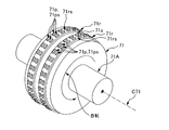
- 3 is a schematic perspective view of an anvil roller 71.
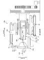
- FIG. 6 is a schematic view when an ultrasonic processing unit 60a according to a second modification is viewed from the rotation direction Dc30 of the rotary drum 30. It is explanatory drawing of the cam curve which concerns on a 3rd modification, Comprising: It is a schematic front view of the ultrasonic welding apparatus 20. FIG. It is the schematic perspective view which looked at the ultrasonic welding apparatus 20b of 2nd Embodiment from upper diagonally forward. It is a schematic side view of the XIV-XIV arrow in FIG. It is a schematic front view of the XV-XV arrow in FIG.
- FIG. 17A is a schematic perspective view of the ultrasonic processing unit 60b according to the second embodiment as viewed from the diagonally forward direction in the rotational radial direction Dr30
- FIG. 17B is a diagram of the unit 60b as viewed from the diagonally rearward direction.
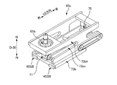
- It is a schematic perspective view of the ultrasonic processing unit 60c which shows the other example of the arrangement
- An ultrasonic welding apparatus that performs an ultrasonic welding process on a sheet-like member that is conveyed while being wound around an outer peripheral surface of a rotating member that rotates around a central axis, The rotating member;
- An ultrasonic treatment unit that rotates about the central axis together with the rotating member,
- the ultrasonic processing unit includes a horn that vibrates ultrasonically, and an anvil that sandwiches the sheet-like member with the horn.
- the ultrasonic processing member of at least one of the horn and the anvil is guided so as to be able to reciprocate in the CD direction intersecting the conveying direction of the sheet-like member, and is wound around the rotating member in the sheet-like member.
- the ultrasonic treatment member reciprocates in the CD direction with respect to the portion being In the predetermined section in the CD direction on the outer peripheral surface of the rotating member, both the horn and the anvil are in contact with the sheet-like member in both the forward path and the return path of the reciprocating movement,
- An ultrasonic welding apparatus for a sheet-like member according to an absorbent article characterized by having an ultrasonic energy adjustment unit that varies the magnitude of ultrasonic energy (J / m).
- the magnitude (J / m) of ultrasonic energy input in the predetermined section is set to the forward path and the return path of the ultrasonic processing member.
- the ultrasonic welding process is firmly performed in the predetermined section, while in the other path, the ultrasonic welding process in the predetermined section can be reduced.
- the misalignment can be made inconspicuous.
- both the horn and the anvil are in contact with the sheet-like member in both the outward path and the return path. Therefore, the horn and the anvil need not be separated from the sheet-like member in the predetermined section, and as a result, the apparatus can be easily realized.
- the ultrasonic energy adjustment unit changes the magnitude (J / m) of ultrasonic energy input per unit length by changing the amplitude of ultrasonic vibration of the horn.
- the ultrasonic energy magnitude (J / m) is changed by changing the amplitude of ultrasonic vibration.
- the size (J / m) can be easily changed with high responsiveness.
- the ultrasonic energy adjustment unit changes the magnitude (J / m) of ultrasonic energy input per unit length, and the magnitude of the pinching force for pinching the sheet-like member between the horn and the anvil. It is desirable to do this by changing
- the magnitude of the ultrasonic energy (J / m) is changed by changing the magnitude of the sandwiching force.
- the magnitude of the sonic energy (J / m) can be changed easily and reliably.
- the ultrasonic energy adjustment unit changes the size (J / m) of ultrasonic energy input per unit length by changing the size of the gap between the horn and the anvil. It is desirable to do it.
- the magnitude of the ultrasonic energy (J / m) is changed by changing the size of the gap between the horn and the anvil. Therefore, it is possible to easily and reliably change the magnitude (J / m) of the ultrasonic energy.
- the ultrasonic energy adjusting unit changes the magnitude (J / m) of ultrasonic energy input per unit length by changing the moving speed value of the ultrasonic processing member in the CD direction. It is desirable to do it.
- the magnitude (J / m) of the ultrasonic energy is changed by changing the moving speed value in the CD direction of the ultrasonic processing member. Therefore, it is possible to reliably change the magnitude (J / m) of the ultrasonic energy.
- the one ultrasonic treatment member of the horn and the anvil has a roller member that is rotatably provided while being arranged outward from the outer peripheral surface of the rotating member, It is desirable that the roller member moves in the CD direction while rolling a rail-like member that extends in the CD direction so as not to move relative to the outer peripheral surface of the rotating member as the other ultrasonic processing member.
- the rail-like member as the other ultrasonic processing member is provided on the outer peripheral surface of the rotating member so as not to be relatively movable. Therefore, the other ultrasonic processing member can maintain the relative positional relationship between the sheet-like member wound around the outer peripheral surface in a constant state. As a result, the ultrasonic welding process can be stabilized.
- An ultrasonic welding apparatus for a sheet-like member according to such an absorbent article It is desirable that both the horn and the anvil reciprocate in the CD direction with the horn and the anvil sandwiching the sheet-like member.
- both the horn and the anvil move relative to the sheet-like member in the CD direction. Therefore, at least the welding soot that can adhere to and accumulate on the horn due to the ultrasonic welding process can be sequentially wiped by the contact with the sheet-like member during the reciprocating movement in the CD direction. It is possible to effectively prevent the deposition of welding flaws.
- An ultrasonic welding apparatus for a sheet-like member according to such an absorbent article It is preferable that at least one of the horn and the anvil is provided with a plurality of protrusions so that a pattern-like welded portion is formed on the sheet-like member.
- the pattern-like welded portion is formed by the plurality of protrusions, so that the design of the welded portion can be improved.
- An ultrasonic welding apparatus for a sheet-like member according to such an absorbent article In both the forward path and the return path, it is desirable that the horn vibrates ultrasonically when the ultrasonic processing member passes through the predetermined section.
- the horn is ultrasonic when passing through the predetermined section in both the forward and backward paths of the ultrasonic treatment member. It is vibrating. That is, when the ultrasonic processing member passes through the predetermined section, the horn vibrates in a direction to sandwich the sheet-like member. Therefore, the dynamic frictional resistance that can occur between the ultrasonic processing member and the sheet-like member when passing through the predetermined section can be reduced. Therefore, the reciprocating movement of the ultrasonic processing member in the CD direction can be performed smoothly.
- An ultrasonic welding method for performing an ultrasonic welding process on a sheet-like member that is conveyed while being wound around an outer peripheral surface of a rotating member that rotates around a central axis, Rotating the sonication unit around the central axis together with the rotating member;
- the horn included in the ultrasonic processing unit vibrates ultrasonically; While sandwiching the sheet-like member in cooperation with the anvil disposed to face the horn, at least one ultrasonic treatment member of the horn and the anvil is wound around the rotating member in the sheet-like member.
- both the horn and the anvil are in contact with the sheet-like member in both the forward path and the return path of the reciprocating movement,
- the ultrasonic welding method for the sheet-like member according to the absorbent article is characterized in that the magnitude (J / m) of the ultrasonic energy differs from each other.
- the magnitude (J / m) of ultrasonic energy input in the predetermined section is set to the forward path and the return path of the ultrasonic processing member.
- the ultrasonic welding process is firmly performed in the predetermined section, and in the other path, the ultrasonic welding process in the predetermined section can be reduced.
- the misalignment can be made inconspicuous.
- both the horn and the anvil are in contact with the sheet-like member in both the outward path and the return path. Therefore, the horn and the anvil need not be separated from the sheet-like member in the predetermined section, and as a result, the method can be easily realized.
- the ultrasonic welding apparatus 20 is an apparatus that forms, for example, a welding portion 14 at a predetermined pitch P1 with a gap in the conveying direction with respect to a continuous sheet-like member 1a conveyed on a production line. And here, the base material 1a of the underpants type disposable diaper 1 is illustrated as the said sheet-like member 1a.
- FIGS. 2A and 2B are explanatory views of the base material 1a of the diaper 1 conveyed to the ultrasonic welding apparatus 20, both of which are schematic perspective views.
- 2A shows a state before the base material 1a of the diaper 1 is folded in half
- FIG. 2B shows a state immediately before the base material 1a is folded in half and conveyed to the ultrasonic welding apparatus 20. Indicates the state.
- the base material 1a of the diaper 1 has a continuous sheet 2a continuous in the transport direction. And at the time of FIG. 2A, on the skin side of the wearer in the continuous sheet 2a, a state in which the absorbent main bodies 4, 4,... It is in. *
- the leg opening 1LH is formed in the base material 1a at this time at a position between the absorbent main bodies 4 and 4 adjacent to each other in the transport direction.
- a leg-hole elastic member 6 for imparting stretchability to the leg-hole opening 1LH is attached along the leg-hole opening 1LH, and each end edge 1ae, 1ae to be the waist-hole opening 1BH.
- the waistline elastic member 7 that imparts stretchability to the waistline opening 1BH is also adhered.
- the continuous sheet 2a is a continuous sheet 2a1 that forms an inner layer facing the wearer's skin when the diaper 1 is worn (hereinafter also referred to as an inner layer sheet 2a1), and an outer layer that faces the non-skin side when the diaper 1 is worn. It has a continuous sheet 2a2 (hereinafter also referred to as an outer layer sheet 2a2), and the inner layer sheet 2a1 and the outer layer sheet 2a2 are joined together by adhesion, welding or the like while being stacked in the thickness direction.
- each of the continuous sheets 2a1 and 2a2 examples include non-woven fabrics, woven fabrics, and films made of a heat-weldable material such as a thermoplastic resin, but a material capable of ultrasonic welding, that is, ultrasonic energy is used.
- the material is not limited to this as long as it is a material that can be melted and joined by frictional heat generation.
- the absorptive main body 4 absorbs excretory fluid, and is formed by molding liquid absorbent fibers such as pulp fibers and liquid absorbent granular materials such as superabsorbent polymers into a predetermined shape such as a substantially hourglass shape.
- the molded body is the main body.
- this molded object is coat
- the base material 1a shown in FIG. 2A is folded in half immediately before being fed into the ultrasonic welding apparatus 20, with the crotch part 13 being the substantially central part in the width direction as a folding position. And thereby, the base material 1a is sent to the ultrasonic welding apparatus 20 in a folded state as shown in FIG. 2B. That is, the part corresponding to the front body 10 and the part corresponding to the back body 11 of the diaper 1 are conveyed to the ultrasonic welding apparatus 20 in a state where they are superimposed one above the other.
- the ultrasonic welding apparatus 20 performs a welding process on the portion 1e corresponding to the side end portion 1e around the trunk of the diaper 1 to form the welding portion 14 on the base material 1a, thereby forming the base material 1a.
- the front body 10 and the back body 11 are joined.
- the welding target portion 1e that is, the portion 1e corresponding to the side end 1e around the trunk of the diaper 1 appears at the product pitch P1 in the conveying direction at the positions on both sides of the absorbent main body 4 on the base material 1a. . Therefore, the ultrasonic welding apparatus 20 forms the welding part 14 by the product pitch P1 in the conveyance direction in the part 1e of the both sides of the absorptive main body 4 among the base materials 1a. At this time, as shown in FIG. 2B, at least a pair of welding portions 14 and 14 are formed side by side in the transport direction for one welding target portion 1 e.
- the base material 1a in which this welding part 14 was formed is sent to a lower process, and in the said lower process, the base material 1a is parted sequentially in the part 1c between said pair of welding parts 14 and 14.
- the diaper 1 having the waist opening 1BH and the leg opening 1LH is generated.
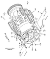
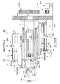
- FIG. 3 is a schematic perspective view of the ultrasonic welding device 20 as viewed obliquely from above and front
- FIG. 4 is a schematic side view taken along arrows IV-IV in FIG. 3
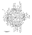
- FIG. It is a schematic front view of the VV arrow.
- FIG. 6 is a schematic side view showing the base 41a and the rotating drum 30 in FIG.
- the direction perpendicular to the conveyance direction of the base material 1a in the production line is also referred to as “CD direction”.
- the CD direction is in the horizontal direction.
- the width direction of this base material 1a and said CD direction are in a parallel relationship on design.
- the thickness direction of the base material 1a is orthogonal to both the continuous direction and the width direction of the base material 1a.
- the ultrasonic welding apparatus 20 is rotated in the same manner as a substantially cylindrical rotating drum 30 (corresponding to a rotating member) that rotates in one direction around a central axis C30 along the CD direction.
- a plurality of (four in this example) ultrasonic processing units 60, 60,... That rotate together with the drum 30 around the central axis C30, and the base material 1a conveyed from the upper process are connected to the outer peripheral surface 30s of the rotary drum 30.
- a pair of guide rolls 90a and 90b for sending out to the lower process while being wound over a predetermined range Rw (FIG. 8) in the rotation direction Dc30 is provided.
- the rotating drum 30 is driven to rotate at a peripheral speed value (m / min) that is substantially the same as the transport speed value (m / min) of the base material 1a that is transported from the upper process. Therefore, the outer peripheral surface 30s of the rotary drum 30 is conveyed along the outer peripheral surface 30s while winding the base material 1a in a state where there is substantially no relative slip with the base material 1a, and the base material 1a moves in the predetermined range Rw. Thereafter, the base material 1a is separated from the outer peripheral surface 30s and sent to the lower process.
- the peripheral speed value (m / min) of the rotating drum 30 is constant for the purpose of facilitating the explanation. That is, in an actual production line, the peripheral speed value (m / min) of the rotary drum 30 can change. For example, the rotating drum 30 rotates at a peripheral speed value different from a constant peripheral speed value (m / min), which is a steady speed value, at the time of start-up and shutdown of the production line and at the time of sudden trouble. However, in most of the operating time for manufacturing the diaper 1, the rotating drum 30 rotates at a constant peripheral speed value (m / min), which is the above-mentioned steady speed value. As described above, the time for rotating at an unsteady speed value is very short. Therefore, even if the description is based on the above assumption, it does not hinder the understanding of the concept of the present invention.
- each of the ultrasonic processing units 60, 60... Is provided at a predetermined angle (for example, 90 °) in the rotation direction Dc30 of the rotary drum 30.
- Each of the ultrasonic processing units 60 is disposed on the outer peripheral surface 30 s of the rotary drum 30 so as not to move relative to each other and oscillates ultrasonically, and the horn 61 in order to sandwich the substrate 1 a together with the horn 61.
- a roller-shaped anvil 71 (corresponding to a roller member) disposed outward in the rotational radial direction Dr30 of the rotary drum 30.
- the horn 61 extends in the CD direction to form a rail shape, and a roller-shaped anvil 71 (hereinafter referred to as anvil roller 71) with respect to the rail-shaped horn 61 (corresponding to a rail-shaped member).
- anvil roller 71 is reciprocated in the CD direction with respect to the portion 1ap on the horn 61 in the substrate 1a. It is possible. Therefore, during the reciprocating movement, ultrasonic energy is selectively supplied from the horn 61 to the portion 1ap sandwiched between the anvil roller 71 and the horn 61 in the base material 1a.
- a welded portion 14 is formed in the portion 1ap of 1a.
- the rotating drum 30 has a cylindrical body whose shape in a cross section with the CD direction as the normal direction is, for example, a perfect circle.
- a shaft member 31 is integrally provided concentrically with the central axis C30 and the shaft member 31 is oriented in the CD direction with the shaft member 31 being concentric with the central axis C30.
- the shaft member 31 is rotatably supported by the six bearing members 31brg. As a result, the rotary drum 30 can rotate about the central axis C30.
- a rotational force is applied to the rotary drum 30 from a servo motor 30M as a drive source via an appropriate rotational force transmission mechanism. As a result, the rotary drum 30 is driven and rotated in one direction.
- the winding transmission device includes both a pulley 31PL provided concentrically and integrally with the one end 31eb of the shaft member 31 and a pulley 30MPL provided concentrically and integrally with the drive rotation shaft of the servo motor 30M.
- the endless timing belt 30TB is wound around the shaft member 31 to transmit the driving torque generated by the servo motor 30M to the shaft member 31 that forms the central axis C30 of the rotary drum 30. Thereby, the rotary drum 30 is driven and rotated by the servo motor 30M.
- the rotational force transmission mechanism is not limited to this.
- gears may be provided in place of the pulleys 31PL and 30MPL, and the rotational force transmission mechanism may be configured by a group of gears.
- the cross-sectional shape of the rotary drum 30 is a perfect circle shape, but is not limited to this, for example, a regular polygon having a number of corners equal to or greater than the number of ultrasonic processing units 60 arranged. It may be a polygonal shape.
- a plurality of (for example, four) ultrasonic processing units 60, 60... are provided at predetermined angles in the rotation direction Dc30 of the rotary drum 30.
- the predetermined angle is set such that the length of the rotation direction Dc30 on the outer peripheral surface 30s of the rotary drum 30 is approximately equal to the length corresponding to one of the diapers 1, and in the example of FIG. , 90 °. Therefore, the number of ultrasonic processing units 60, 60... Is four.
- the servo motor 30M as a drive source is rotated so that the rotary drum 30 rotates by the predetermined angle as the base material 1a is fed from the upper process by a length corresponding to one diaper 1.
- each ultrasonic processing unit 60 is associated with each welding target portion 1e in the substrate 1a to perform ultrasonic welding. Processing is to be performed.
- a control unit such as a computer or a PLC (programmable logic controller)
- each ultrasonic processing unit 60 is associated with each welding target portion 1e in the substrate 1a to perform ultrasonic welding. Processing is to be performed.
- Such a rotation operation is realized, for example, by controlling the position of the servo motor 30M based on the synchronization signal.
- the synchronization signal is, for example, a rotation of a rotary encoder or the like that measures the conveyance amount of the substrate 1a in a device that is a reference for a production line (for example, a rotary die cutter device that punches and forms the leg opening 1LH in FIG. 2A). Output from a detection sensor (not shown).
- the synchronizing signal is obtained by assigning each rotation angle value from 0 ° to 360 ° in proportion to the conveyance amount, with the conveyance amount for one diaper as a product (substantially the same value as the above-mentioned product pitch P1) as a unit conveyance amount. Is a rotation angle signal.
- the synchronization signal is not limited to any rotation angle signal.
- a digital signal obtained by assigning each digital value of 0 to 8191 to the unit carry amount in proportion to the carry amount may be used as the synchronization signal.
- each of the ultrasonic processing units 60 has already been arranged along the CD direction fixed to a column 41 (described later) so as not to move relative to the outer peripheral surface 30 s of the rotary drum 30. It has the rail-shaped horn 61 described above and an anvil roller 71 provided so as to be reciprocally movable in the CD direction while rolling on the horn 61. As shown in FIGS. 3, 5, and 6, the horn 61 has a substantially flat surface 61 s facing outward in the rotational radial direction Dr ⁇ b> 30 of the rotating drum 30, and the anvil roller 71 rolls on the substantially flat surface 61 s. It has become.
- the substantially flat surface 61s functions as an oscillation surface 61s that vibrates ultrasonically.
- the oscillating surface 61s is fixed so as to be flush with the outer peripheral surface 30s of the rotating drum 30 or slightly outward in the rotational radial direction Dr30.
- the length of the oscillating surface 61s in the CD direction is designed such that the oscillating surface 61s protrudes from both sides of the substrate 1a wound around the outer peripheral surface 30s of the rotating drum 30 in the CD direction (for example, FIG. 10). Therefore, based on the reciprocation of the anvil roller 71 in the CD direction, it is possible to form the weld portion 14 having a length over the entire length of the base material 1a in the CD direction.
- the horn 61 is connected to an oscillator (both not shown) via a booster and a converter.
- the oscillator has an electric circuit, and when the electric circuit is supplied with power from an appropriate power source, it generates an electric signal having a constant frequency of 20 kHz to 35 kHz.
- the converter converts the electric signal having the constant frequency sent from the oscillator into mechanical vibration having the same frequency by a piezo element or the like.
- the booster amplifies the mechanical vibration sent from the converter and transmits it to the horn 61, whereby the oscillation surface 61s of the horn 61 is ultrasonically vibrated in the normal direction of the surface 61s.
- the magnitude (J) of the ultrasonic energy input to the substrate 1a by the ultrasonic vibration is changed by changing the amplitude of the ultrasonic vibration of the oscillation surface 61s or the horn 61 when the frequency is constant.
- the oscillation surface 61s can be changed by changing the magnitude (N) of the force (hereinafter also referred to as the pinching force) for sandwiching the base material 1a with the anvil roller 71.
- the magnitude (N) of the pinching force is constant, if the amplitude is increased or decreased, the resistance to vibration is increased or decreased in conjunction with this, so that the power consumption in the oscillator is also increased or decreased.
- the ultrasonic energy thrown into the base material 1a is increased / decreased by the increase / decrease in amplitude.
- the amplitude is constant, if the magnitude (N) of the pinching force is increased or decreased, the resistance to vibration increases or decreases in conjunction with this, so that the power consumption in the oscillator also increases or decreases.
- Power consumption is generally thrown into the substrate 1a as ultrasonic energy. Therefore, the ultrasonic energy applied to the substrate 1a is also increased or decreased by increasing or decreasing the pinching force (N).
- the former amplitude change can be performed by an oscillator. That is, the oscillator is configured to be able to change the amplitude of the ultrasonic vibration to an arbitrary value based on a control signal transmitted from an ultrasonic energy adjustment unit (not shown) configured by a computer or a PLC. . Further, the change in the magnitude (N) of the latter pinching force can be performed by an air cylinder 75 (see FIGS. 7A and 7B) attached to the anvil roller 71 described later, which will be described later. . Incidentally, in this example, the oscillator is configured so that the amplitude of the ultrasonic vibration (the distance traveled from the balance position to the maximum displacement) can be adjusted to an arbitrary value between 0 microns and 30 microns. The range of the correct amplitude is not limited to this.
- the anvil roller 71 is opposed to the oscillation surface 61 s of the horn 61, and is further outward from the oscillation surface 61 s in the rotational radial direction Dr30 of the rotary drum 30. Placed in position. And it is provided so that it can reciprocate in CD direction, rolling the oscillation surface 61s.
- Such a reciprocating movement of the anvil roller 71 is realized, for example, as follows.
- a polygonal cylindrical column is coaxial with the shaft member 31 that forms the central axis C ⁇ b> 30 of the rotating drum 30.
- 41 is provided. Most of the column 41 is accommodated on the inner peripheral side of the rotary drum 30, and one end 41 eb in the CD direction protrudes from the rotary drum 30.
- the column 41 is integrally connected to the shaft member 31 of the rotary drum 30 by a connecting member (not shown), and thereby rotates around the central axis C30 together with the rotary drum 30.
- the direction in which the column 41 protrudes from the rotary drum 30 with respect to the CD direction is referred to as “rear”, and the opposite direction is referred to as “front”.
- the cross-sectional shape of the column 41 (the shape in the cross-section with the CD direction as the normal direction) is, for example, a regular number having the same number of corners as the number of ultrasonic processing units 60, 60.
- the column 41 is a cylindrical body having the same number of wall portions 41w, 41w as the number of ultrasonic processing units 60, 60.
- the cross-sectional shape is a square, that is, the column 41 is a square having four walls 41w, 41w. It is a cylinder. Each wall 41w is associated with one ultrasonic processing unit 60.
- each wall portion 41w is provided with a linear guide 45 for reciprocating the anvil roller 71 of the ultrasonic processing unit 60 in the CD direction.
- the linear guide 45 includes a rail 45R that is fixed to the wall 41w and extends in the CD direction, and slide blocks 45SB and 45SB that are slidable on both sides in the CD direction and engage with the rail 45R.
- a support unit 73 that supports the anvil roller 71 is fixed to the slide blocks 45SB and 45SB.
- FIG. 7A and 7B are explanatory views of the support unit 73.
- FIG. 7A is a schematic perspective view of the support unit 73 as viewed from the diagonally forward direction in the rotational radial direction Dr30
- FIG. 7B is a schematic perspective view of the unit 73 as viewed from the diagonally rearward direction.
- the support unit 73 includes a base portion 73b fixed to the slide blocks 45SB, 45SB, and a seesaw-like member 73ss supported in a swingable manner on the base portion 73b and extending in the CD direction.
- the seesaw-like member 73ss is swingably supported by the base part 73b by a support shaft 73ssp provided at a substantially central part in the CD direction. That is, both the front end portion 73ssef and the rear end portion 73sseb of the seesaw-like member 73ss can swing in the rotational radial direction Dr30 of the rotary drum 30, and more specifically, the front end portion 73ssef and the rear end portion 73sseb. Are operated in substantially opposite directions.
- the anvil roller 71 is rotatably supported by the front end portion 73ssef.
- the rear end portion 73sseb is, for example, a double-acting type as a drive source for causing the seesaw-like member 73ss to swing.
- the air cylinder 75 is provided.
- the air cylinder 75 includes a cylinder part 75c and a piston (not shown) that is slidably provided in the cylinder part 75c while defining two pressure chambers in the cylinder part 75c. And a piston rod 75pr provided integrally with the piston and capable of protruding and retracting from the cylinder portion 75c.
- the tip end portion of the piston rod 75pr is connected to the rear end portion 73sseb of the seesaw-like member 73ss, and the cylinder portion 75c is fixed to the base portion 73b.
- the anvil roller 71 is pressed against the oscillation surface 61s of the horn 61 or the oscillation surface 61s through the operation of the piston rod 75pr.
- the anvil roller 71 can be separated from the
- the base material 1a can be sandwiched between the anvil roller 71 and the oscillating surface 61s of the horn 61. If the supply pressure (MPa) is changed, the magnitude (N) of the sandwiching force of the substrate 1a can be adjusted.
- a pressure adjustment valve (not shown) is provided in each compressed air supply path to each pressure chamber, although the structure etc. which provided switching valves (not shown), such as an electromagnetic valve which switches each supply path
- the driving force for reciprocating the support unit 73 of the anvil roller 71 in the CD direction is generated from the rotation operation of the column 41. That is, the column 41 is rotated integrally with the rotary drum 30 in the rotation direction Dc30, but the ultrasonic welding apparatus 20 converts the rotation operation into a reciprocating movement operation in the CD direction and transmits it to each support unit 73. Thus, a cam mechanism for driving these support units 73 is provided.
- the cam mechanism has a cylindrical member 51 inserted coaxially on the inner peripheral side of the column 41, for example, and the cylindrical member 51 rotates to an appropriate support member 55 on the ground GND side. It is fixed impossible.
- a rib-shaped cam 51r is provided on the outer peripheral surface 51s of the cylindrical member 51.
- a pair of cam followers 53, 53 are provided on the base portion 73b of the support unit 73. The cam followers 53 and 53 are engaged by sandwiching the rib-shaped cam 51r from the front and rear.
- the rib-like cam 51r is provided in an endless manner that is continuous with the rotation direction Dc30 of the rotary drum 30, and the position of the cam 51r in the CD direction changes corresponding to the position of the rotation direction Dc30.
- a cam curve is set.
- the reciprocating motion of the support unit 73 is prescribed
- both the forward and backward movements of the support unit 73 have a constant moving speed value (the same value).
- the cam curve is set so that the support unit 73 moves at (m / min).
- the first angle range Rw ⁇ b> 1 and the second angle range Rw ⁇ b> 1 have the same angle size and do not overlap.
- An angle range Rw2 is set.
- the shape of the portion is such that the position of the rib-shaped cam 51r in the CD direction is the position of the rotational direction Dc30. The shape is such that it is displaced forward in proportion to the change of.
- the unit 73 and the attached anvil roller 71 are set forward from the backward limit Pb (FIG. 6) set backward in the CD direction. It moves to the forward limit Pf (FIG. 6) at a constant moving speed value (m / min).
- the shape of the portion is such that the position of the rib-shaped cam 51r in the CD direction is the position of the rotational direction Dc30. The shape is such that it is displaced rearward in proportion to the change of. Therefore, when the support unit 73 passes through the second angle range Rw2, the unit 73 and the attached anvil roller 71 move from the forward limit Pf to the reverse limit Pb with the same moving speed value (m / Move in minutes).
- the first angle range Rw1 and the second angle range Rw2 are set adjacent to each other, so that the anvil roller 71 that has reached the forward limit Pf by the forward movement is immediately It turns back and performs backward movement.
- the backward operation may be performed after the anvil roller 71 has stopped a little at the forward limit Pf.
- the anvil roller 71 in the state where the anvil roller 71 is positioned at the retreat limit Pb, the anvil roller 71 has completely traversed the base material 1a and is not in contact with the base material 1a (for example, FIG. reference).
- the cam curve is set so that the anvil roller 71 stays at the backward limit Pb. Therefore, in both the winding start position Pws that forms the start end of the winding range Rw of the base material 1a and the winding end position Pwe that forms the end of the winding range Rw, the anvil roller 71 is positioned at the retreat limit Pb.
- the anvil roller 71 does not hinder the winding operation of the base material 1a around the outer peripheral surface 30s of the rotating drum 30 and the releasing operation of the winding state.
- Such anvil roller 71 is configured to rotate along with the reciprocating movement in the CD direction. That is, in forward movement, it rotates at a circumferential speed value (m / min) that is substantially the same as the forward moving speed value (m / min) so as to roll forward, and in backward movement, it moves backward so as to roll backward. It rotates at a peripheral speed value (m / min) that is substantially the same as the speed value (m / min). And thereby, it rolls and moves on the base material 1a in the CD direction in a state where there is almost no relative slip with the base material 1a.
- Such rotation operation may be performed by the driven rotation of the anvil roller 71.
- the anvil roller 71 is supported on a support unit 73 via an appropriate bearing member (not shown), so that it can be rotated with a very small rotational resistance while the air described above.
- the anvil roller 71 is pressed by the cylinder 75 against the oscillation surface 61s of the horn 61 through the substrate 1a. If it does so, the anvil roller 71 will acquire rotational force from the base material 1a with a reciprocating movement operation, and will rotate with it, Therefore, the anvil roller 71 rotates by a driven rotation.
- 7A and 7B is provided with a motion conversion mechanism that converts the reciprocating motion of the support unit 73 into a rotational motion and transmits it to the anvil roller 71 for the purpose of reliably performing the rotation operation.
- a motion conversion mechanism is a so-called winding transmission mechanism.
- the pulley 71APL is fixed to the shaft portion 71A that is concentrically and integrally provided with the circular center of the anvil roller 71, and the pulley 73sspPL is also rotatably supported on the support shaft 73ssp of the seesaw-like member 73ss. ing.
- An endless timing belt 73TB1 is wound around the pulleys 71APL and 73sspPL.
- another pulley 73sspPL2 is concentrically and integrally fixed to the latter pulley 73sspPL, and another pulley 73bebPL is rotatably supported by the rear end 73beb of the base portion 73b of the support unit 73.
- a separate endless timing belt 73TB2 is also wound around the other pulleys 73sspPL2 and 73bebPL, and a part of the timing belt 73TB2 is connected to the column 41 via a connecting member (not shown). Has been.
- the anvil roller 71 rotates by this amount of movement. That is, if the support unit 73 moves forward, the anvil roller 71 rotates in the forward direction with the same rotation amount as the movement amount of the advancement. On the other hand, if the support unit 73 moves backward, the rotation amount is the same as the movement amount of the backward movement. Rotates in the reverse direction. Therefore, the anvil roller 71 can reliably roll on the base material 1a without reciprocally sliding with respect to the base material 1a during the reciprocating movement in the CD direction. This is related to the formation of the pattern-shaped welded portion 14 by the anvil roller 71 as will be described later.
- FIG. 9 shows a schematic perspective view of the anvil roller 71.
- a plurality of protrusions 71p, 71p,... are provided on the peripheral surface 71s of the anvil roller 71 for the purpose of forming the patterned welded portion 14 on the base material 1a. More specifically, first, endless ribs 71r, 71r are provided on the circumferential surface 71s of the anvil roller 71 in a line along the rotation axis C71 of the anvil roller 71 along the entire length in the circumferential direction.
- a plurality of island-shaped protrusions 71p, 71p,... Are provided in a pattern having a certain regularity on the top surface 71rs of each rib 71r.
- a low-pressure squeezed portion is formed in the base material 1a by the top surface 71rs of the rib 71r, and the high-pressure squeezed by the top surfaces 71ps, 71ps,... Part is formed. And thereby, the welding part 14 is formed in the pattern shape which has several high pressing parts.
- the anvil roller 71 rotates in accordance with the reciprocating movement in the CD direction, and rolls without substantially sliding relative to the base material 1a. Therefore, by design, the protrusions 71p, 71p,... Of the anvil roller 71 should hit the same position of the substrate 1a in the forward and backward movements of the reciprocating movement. It is assumed that the high pressure parts formed on the return path are completely overlapped with each other.
- the base material 1a may slightly move between the forward path and the return path, or the rotation operation of the anvil roller 71 may not be able to completely follow the reciprocating movement operation in the CD direction.
- the high-pressure parts that should overlap in design in the forward path and the return path may be shifted from each other. Then, the appearance of the welded portion 14 is deteriorated, and the commercial value of the diaper 1 is reduced.
- cross section A1a corresponding to a predetermined section
- the magnitude (J / m) of ultrasonic energy input per unit length in the CD direction when traversing the crossing section A1a is determined between the forward path and the return path of the reciprocating movement. It is different.
- ultrasonic energy is applied while maintaining the size per unit length in the CD direction (J / m) constant over the crossing section A1a in the outbound path, and also in the inbound path. While the size per unit length in the CD direction (J / m) is kept constant over the section A1a, the ultrasonic energy is applied, but the former size (J / m) Is larger than the size (J / m) of the latter return path.
- the ultrasonic welding process can be performed firmly on the base material 1a in the forward path, and the ultrasonic welding process on the base material 1a can be reduced in the return path. That is, in the return path, the welded portion 14 is formed lightly or not at all. Therefore, even if the high pressing part of the welding part 14 formed in the outward path and the high pressing part of the welding part 14 formed in the backward path are misaligned, the positional deviation can be made inconspicuous.
- the ultrasonic energy adjustment unit constantly monitors the position in the CD direction when the support unit 73 reciprocates. Such monitoring is performed indirectly based on, for example, a signal output from a rotary encoder (not shown) as a rotation detection sensor that detects the rotation angle of the rotary drum 30. That is, as described above, the correspondence relationship between the position in the rotational direction Dc30 of the rotary drum 30 and the position in the CD direction is uniquely determined beforehand by the cam curve of the rib-shaped cam 51r described above. If the position of the rotation direction Dc30 of the unit 73 is known, it is possible to recognize at which position in the CD direction the support unit 73 is currently located. On the other hand, the position of the support unit 73 in the rotation direction Dc30 can be detected based on the value of the rotation angle (0 ° to 360 °) indicated by the output signal of the encoder.
- the memory of the adjustment unit corresponds to, for example, the rotation angle value data corresponding to the position immediately before the crossing section A1a has been crossed in the forward path, or the position at which the crossing section A1a has been crossed.
- Data on the value of the rotation angle or data on the value of the rotation angle corresponding to the position immediately after the crossing of the cross section A1a is stored in advance.
- the rotation angle value data corresponding to the position immediately before the crossing section A1a is completed, or the position where the crossing section A1a is completed
- the rotation angle value data or the rotation angle value data corresponding to the position immediately after traversing the crossing section A1a is stored in advance.
- the adjustment unit detects that the value of the rotation angle indicated by the output signal of the encoder coincides with or exceeds the value of the rotation angle in the memory, the amplitude is adjusted at the same time or after a predetermined time has elapsed. Change to a larger amplitude for the outbound path. In this way, the amplitude in the forward path can be surely made larger than the amplitude in the return path.
- the amplitude in the forward path is set to an arbitrary value in the range of 15 to 30 microns, for example, and in this example, is set to 30 microns.
- the amplitude in the return path is set to an arbitrary value in the range of 0% to 50% of the amplitude in the forward path, for example, and is set to 30% in this example. And if it is set in this way, it is possible to reliably form the welded portion 14 in the outward path, and more reliably not to form the welded portion 14 in the return path. The positional deviation from the portion 14 can be made even less conspicuous. Note that the optimum value of the amplitude can be obtained through actual machine experiments or the like.
- the magnitude (N) of the force for sandwiching the base material 1a between the anvil roller 71 and the oscillating surface 61s of the horn 61 is maintained at a constant value in both the forward path and the return path across the transverse section A1a. ing.
- the magnitude of the ultrasonic energy input in the return path (J / m) is surely made smaller than the magnitude of the ultrasonic energy input in the forward path (J / m) by changing the amplitude. can do.
- the optimum value of the pinching force (N) can also be obtained through actual machine experiments and the like.
- the operation of separating the anvil roller 71 from the base material 1a by the air cylinder 75 described above is also possible.
- the horn 61 and the The anvil roller 71 cooperates with each other to sandwich the substrate 1a. That is, both the horn 61 and the anvil roller 71 are in contact with the base material 1a in both the forward path and the return path, and the anvil roller 71 that can be separated from the base material 1a is not separated from the base material 1a. Therefore, the relative positional relationship between the anvil roller 71 and the horn 61 in the cross section A1a can be maintained in a constant state, and as a result, the ultrasonic welding process can be stabilized.
- the separation operation when performing the separation operation, as described above, the separation operation must be performed in a minute time of a part of several hundred milliseconds, which is difficult to execute, and the ultrasonic welding apparatus 20 In this example, the ultrasonic welding apparatus 20 can be realized without any problem because it is not separated.
- the “crossing section A1a” is illustrated as an example of the predetermined section in the CD direction on the outer peripheral surface 30s of the rotary drum 30. Then, as is clear from FIG. 10, the “crossing section A1a” means that “the base material 1a is wound around the design position of the outer peripheral surface 30s of the rotating drum 30 without meandering or the like. The section A1a corresponding to the position from the position where the crossing 1a is crossed in the CD direction to the position where the crossing is completed ”. In the above description, the amplitude in the crossing section A1a is different between the forward path and the return path. Not limited to this.
- the amplitude in a specific section (corresponding to a predetermined section) in the crossing section A1a may be different between the forward path and the return path, that is, in the remaining sections other than the specific section, the amplitude is set to the forward path and the return path. It does not have to be different. Also in this case, the position shift between the welded portion 14 formed in the forward path in the portion corresponding to the specific section in the base material 1a and the welded portion 14 formed in the return path in the portion corresponding to the specific section. Can be made inconspicuous.
- a plurality of specific sections may be set so as not to overlap with the cross section A1a.
- the first specific section and the second specific section may be set at positions where the positions in the CD direction are different from each other.
- the amplitude of the ultrasonic vibration when the anvil roller 71 passes through the first specific section is made different between the forward path and the return path, and the amplitude of the ultrasonic vibration when it passes through the second specific section is changed. It will be different for the outbound and inbound trips.
- the amplitude in the first specific section and the amplitude in the second specific section need not be the same, and may be different.
- the ultrasonic energy adjustment unit controls the oscillator, and thereby maintains the amplitude of the ultrasonic vibration of the oscillation surface 61s of the horn 61 at a constant value of, for example, 30 microns.
- the adjusting unit controls the above-described pressure adjusting valve for the air cylinder 75 attached to the support unit 73, and thereby the base material with a large pinching force (N) over the transverse section A1a in the forward path.
- the substrate 1a is sandwiched across the crossing section A1a with a clamping force (N) smaller than the clamping force in the forward path.
- the magnitude (J / m) of ultrasonic energy input per unit length in the CD direction in the crossing section A1a on the forward path is input per unit length in the CD direction on the crossing section A1a on the return path. Larger than the magnitude (J / m) of ultrasonic energy to be generated.
- the magnitude (N) of the pinching force in the return path is set to an arbitrary value of 5% to 50% of the magnitude (N) of the pinching force in the forward path, preferably 5% to 30%. Set to an arbitrary value. And if it does in this way, the position shift of the welding part 14 can be made still more inconspicuous.
- FIG. 11 is a schematic view when the ultrasonic processing unit 60a according to the second modification is viewed from the rotation direction Dc30 of the rotary drum 30.
- the magnitude of the ultrasonic energy (J / m) is different between the forward path and the return path by changing the size of the gap G between the transmission surface 61s of the horn 61 and the anvil roller 71. It is
- the amplitude is not changed between the forward path and the return path, but is a constant value.
- the amplitude is changed between the forward path and the return path. Yes. More specifically, in the forward path, the size of the gap G is set to be small over the crossing section A1a, while in the return path, the size of the gap G is set to be larger than the size of the gap G in the outbound path. It is set large.
- the magnitude (J / m) of ultrasonic energy input per unit length in the CD direction in the crossing section A1a on the forward path is equal to the magnitude of ultrasonic energy input in the cross section A1a on the return path. It is made larger than (J / m).
- this second modified example also has a support unit 73 a having substantially the same structure as the support unit 73 of the first embodiment. That is, the anvil roller 71 is rotatably supported by the front end portion 73ssef of the seesaw-like member 73ss described above, and the seesaw-like member 73ss is also a support shaft at a substantially central portion in the CD direction as described above. At 73ssp, the base unit 73ba of the support unit 73a is rotatably supported. As a result, the seesaw-like member 73ss can be operated in a substantially reverse manner with respect to the front end 73ssef and the rear end 73sseb, that is, can be swung like a seesaw.
- the support unit 73a of the second modified example includes an air spring 76 that applies a force in the direction in which the gap G is reduced to the seesaw-like member 73ss as a drive source for causing the seesaw-like member 73ss to swing. It has a leaf spring 77 as an elastic member that applies a force in the direction in which the gap G expands to the seesaw-like member 73ss.
- the air spring 76 has a substantially sealed bag body 76b.
- the bag body 76b expands when the inside is pressurized by supplying air, and contracts when the inside is depressurized by discharging air.
- the bag body 76b is inserted between the base portion 73ba of the support unit 73a and the rear end portion 73sseb of the seesaw-like member 73ss, and thereby the rotation radius of the rotary drum 30 with respect to the rear end portion 73sseb. It contacts from the inside of the direction Dr30.
- the leaf spring 77 is supported by an appropriate stay member 73bas attached to the base portion 73ba of the support unit 73a so as to come into contact with the rear end portion 73sseb of the seesaw-like member 73ss from the outside in the rotational radial direction Dr30. ing. And thereby, the leaf
- the bag body 76b when the inside of the bag body 76b is pressurized by increasing the supply pressure (MPa) while supplying air to the inside of the bag body 76b, the bag body 76b is expanded through the expansion of the bag body 76b. A force directed outward in the radial direction Dr30 of the rotary drum 30 is applied to the rear end portion 73sseb. Then, when the magnitude of the force becomes larger than the force necessary for crushing the leaf spring 77 outward in the rotational radial direction Dr30, the rear end 73sseb is resisted against the elastic force of the leaf spring 77.
- MPa supply pressure
- the seesaw-like member 73ss rotates so as to move outward in the same rotational radial direction Dr30, whereby the anvil roller 71 of the front end 73ssef moves inward in the same rotational radial direction Dr30, As a result, the gap G between the horn 61 and the oscillation surface 61s is reduced.
- the bag body 76b when the pressure inside the bag body 76b is reduced by lowering the air supply pressure (MPa) to the inside of the bag body 76b, the bag body 76b is brought into the rear end portion 73sseb through the contraction of the bag body 76b. The force applied to it becomes smaller.
- the rear end portion 73sseb moves inward in the same radial direction Dr30.
- the member 73ss rotates, and thereby the anvil roller 71 of the front end portion 73ssef moves outward in the rotational radius direction Dr30, and as a result, the gap G between the horn 61 and the horn 61 increases.
- a compressed air source such as a compressor is connected to the bag body 76b via a supply path (not shown) such as piping.
- a pressure regulating valve (not shown) is disposed in the supply path between the compressed air source and the bag body 76b can be exemplified.
- the size of the gap G is changed by the above-described ultrasonic energy adjusting unit controlling the pressure adjusting valve.
- the mechanism for supplying and discharging compressed air is not limited to the above.
- the leaf spring 77 is illustrated as an example of an elastic member that applies a force in the direction of expanding the gap G, but the present invention is not limited thereto.
- a disc spring or a coil spring may be used.
- it may be a rod-like member that is elastically deformed.
- one end of the rod-shaped member abuts against the rear end 73sseb of the seesaw-shaped member 73ss from the outside in the rotational radial direction Dr30, and two portions other than the one end
- the base unit 73ba of the support unit 73a is supported so as not to rotate.
- an outward force in the rotational radius direction Dr30 is applied from the air spring 76 to the rear end portion 73sseb, the rod-like member is elastically deformed, whereby the size of the gap G is changed.
- the amplitude and the magnitude (N) of the pinching force are maintained at constant values without changing between the forward path and the return path.
- the moving speed value (m / min) in the CD direction of the anvil roller 71 is changed between the forward path and the return path. More specifically, the traveling speed value (m / min) is set to be small over the crossing section A1a in the forward path, so that it moves at a low speed in the CD direction.
- the moving speed value (m / min) is set to be larger than the moving speed value (m / min) in the forward path across the crossing section A1a, so that it moves at high speed in the CD direction.
- the magnitude (J / m) of ultrasonic energy input per unit length in the CD direction on the forward path is larger than the magnitude (J / m) of ultrasonic energy input on the return path. Is done.
- the movement speed value (m / min) in the CD direction of the anvil roller 71 is changed by setting the cam curve described above. That is, in this example, instead of the ultrasonic energy adjustment unit formed of the computer or the like used in the first embodiment, the above-described rib-shaped cam 51r and cam followers 53 and 53 function as the ultrasonic energy adjustment unit. ing. More specifically, it is as follows.
- the forward curve movement operation corresponding to the first angle range Rw1 in the rotation direction Dc30 of the rotary drum 30 is set in the cam curve of the cam 51r.
- a backward movement operation that is a backward operation is set in correspondence with the second angle range Rw2 in the rotation direction Dc30. Therefore, as shown in FIG. 12, by setting the size of the first angle range Rw1 larger than the size of the second angle range Rw2, the forward movement operation is made slower than the backward movement operation. Can do. That is, the traveling speed value (m / min) on the forward path can be set smaller than the traveling speed value (m / min) on the backward path.
- the roller-shaped anvil 71 which is the anvil roller 71 is provided.
- the rail-shaped anvil extending to the CD is fixed so as not to be relatively movable with respect to the rotating drum 30, and the roller-shaped horn (hereinafter referred to as “horn roller”) is moved outward in the rotational radial direction Dr 30 from the anvil. It may be arranged.
- the configuration of the horn roller is the same as that disclosed in JP 10-513128 A, and since this configuration is well known, its detailed description is omitted.
- FIG. 13 is a schematic perspective view of the ultrasonic welding device 20b as viewed obliquely from above
- FIG. 14 is a schematic side view taken along arrow XIV-XIV in FIG. 13, and FIG. It is a schematic front view of the XV-XV arrow in the inside.
- FIG. 16 is a schematic side view showing the substrate 1a and the rotating drum 30 removed from FIG.
- FIG. 17A is a schematic perspective view of the ultrasonic processing unit 60b as viewed from the diagonally forward direction in the rotational radial direction Dr30
- FIG. 17B is a schematic perspective view of the unit 60b as viewed from the diagonally outward direction. is there.
- the horn 61 of the ultrasonic processing unit 60 is fixed to the column 41 so as not to move relative to the rotary drum 30, thereby As shown in FIG. 6, no reciprocating movement was performed in the CD direction.
- the second embodiment as shown in FIG. 16, in conjunction with the reciprocating movement of the anvil roller 71 in the CD direction, the horn 61b also reciprocates in the CD direction.
- Other points are substantially the same as in the first embodiment. Therefore, in the following, this difference will be mainly described, the same components as those in the first embodiment will be denoted by the same reference numerals, and description thereof will be omitted.
- the horn 61b can also be reciprocated in the CD direction.
- the anvil roller 71 and the horn 61b are configured to be able to sandwich the base material 1a in cooperation with each other.
- the horn 61b is fixed to the base portion 73b of the support unit 73, while the anvil roller 71 is supported by the seesaw-like member 73ss.
- the welding soot can adhere and accumulate particularly on the non-rotating horn 61b.
- the horn 61b at the time of such a reciprocating movement can wipe off the welding flaw adhering to itself sequentially by contact and sliding with the base material 1a. As a result, it is possible to effectively prevent the deposition of welding soot on the horn 61b.
- the rotary drum 30 has a cylindrical portion 30 having an outer peripheral surface 30 s as a main body.
- the cylindrical portion 30 includes an anvil roller 71 and a horn.
- a slit-shaped notch 30SL is formed so as to extend from the rear to the front in the CD direction so as to correspond to the reciprocating path of 61b in the CD direction.
- the position of the cutout portion 30SL is a space, that is, the inner peripheral side and the outer peripheral side of the cylindrical portion 30 communicate with each other.
- the anvil roller 71 and the horn 61b quickly reciprocate in the CD direction without interfering with the cylindrical portion 30 while sandwiching the base material 1a from both sides of the rotational radial direction Dr30 of the rotary drum 30 at the position of the cutout portion 30SL. Can move.
- the horn 61b also moves back and forth in the CD direction together with the anvil roller 71. Therefore, the shape of the horn 61b is a rail shape extending in the CD direction as exemplified in the first embodiment. There is no need, and the shape can be freely selected. Therefore, in the second embodiment, as shown in FIG. 17A, the shape of the horn 61b is a substantially cylindrical body 61b whose axial direction is directed to the rotational radius direction Dr30 of the rotary drum 30.
- the circular end surface 61bs in the substantially cylindrical body 61b forms an oscillation surface 61bs that vibrates ultrasonically, and the end surface 61bs faces outward in the rotational radius direction Dr30 of the rotary drum 30, thereby
- the horn 61 b is fixed to the base portion 73 b of the support unit 73 with the end face 61 bs facing the peripheral surface 71 s of the anvil roller 71.
- the basic configuration of the ultrasonic welding apparatus 20b of the second embodiment is substantially the same as the apparatus disclosed in Japanese Patent Application Laid-Open No. 2013-193450, and thus detailed description thereof is omitted.
- the substantially cylindrical horn 61b is disposed inward in the rotational radial direction Dr30 of the rotating drum 30 rather than the anvil roller 71.
- the arrangement relationship in the rotation radius direction Dr30 may be reversed. That is, you may arrange
- the horn 61b is supported by the front end portion 73ssef of the seesaw-like member 73ss, and the anvil roller 71 is supported by the base portion 73b.
- the anvil roller 71 is supported by the seesaw-like member 73ss. Further, the base portion 73b is provided with an overhang portion 73bh that protrudes beyond the position of the seesaw-like member 73ss outward in the rotational radius direction Dr30, and the horn 61b is supported by the overhang portion 73bh. However, it may be configured in this way.
- the peripheral speed value (m / min) of the rotating drum 30 has been described on the premise that it is easy to explain. However, as described above, actually, the rotating drum 30
- the peripheral speed value of 30 may change. In that case, if the amplitude of the ultrasonic vibration is increased or decreased in conjunction with the increase or decrease of the peripheral speed value (m / min) of the rotating drum 30, it is introduced per unit length in the CD direction in the forward path.
- the magnitude relationship between the magnitude of ultrasonic energy (J / m) and the magnitude of ultrasonic energy (J / m) input per unit length in the CD direction on the return path is expressed as the peripheral speed value (m / It can be maintained regardless of the change in minutes).
- the anvil roller 71 has two ribs 71r and 71r on the peripheral surface 71s, and a plurality of protrusions 71p on the top surface 71rs of each rib 71r. 71p are provided in a pattern, but the present invention is not limited to this.
- two ribs along the CD direction may be provided on the oscillation surface 61s of the rail-shaped horn 61 shown in FIG. 6, and a plurality of protrusions may be provided in a pattern on the top surface of each rib.
- the rib 71r may not be provided, that is, a plurality of protrusions 71p, 71p,... May be provided in a pattern directly on the peripheral surface 71s of the anvil roller 71 or the oscillation surface 61s of the horn 61.
- the ultrasonic energy adjustment unit changes the magnitude (J / m) of ultrasonic energy based on the signal indicating the rotation angle of the rotary drum 30 output from the rotary encoder.
- appropriate sensors such as limit switches and proximity switches are provided at the front and rear positions in the CD direction of the rotating drum 30, and the anvil roller 71 crosses the section A1a based on the output signal from the sensors.
- the ultrasonic energy adjustment unit detects that the time is just before the crossing is completed, the time when the crossing is completed, or just after the crossing is completed, and the magnitude of the ultrasonic energy is detected. (J / m) may be changed.
- the amplitude of the ultrasonic vibration in the forward path related to the reciprocating movement in the CD direction is larger than the amplitude of the ultrasonic vibration in the return path, but the present invention is not limited to this.
- the amplitude relationship may be reversed. That is, the amplitude of the ultrasonic vibration in the return path related to the reciprocation in the CD direction may be larger than the amplitude of the ultrasonic vibration in the forward path.
- the oscillating surface 61bs of the horn 61b exceeds the direction in which the base material 1a is sandwiched.
- the sound wave is vibrating. Therefore, the dynamic frictional resistance that can be generated between the horn 61b and the base material 1a when the horn 61b passes through the transverse section A1a can be reduced, and as a result, the horn 61b can be smoothly reciprocated.
- the disposable diaper 1 that is attached to the object to be worn and absorbs the excretory fluid is exemplified as an example of the absorbent article, but the present invention is not limited thereto. That is, as long as it absorbs excreted fluid such as urine and menstrual blood, the absorbent article according to the present invention can be obtained.
- the absorbent article according to the present invention can be obtained.
- sanitary napkins, pet sheets that absorb pet's excretion fluid, and the like are also included in the concept of the absorbent article according to the present invention.
- the rotating drum 30 is exemplified as the rotating member, but the present invention is not limited thereto. That is, any member that can rotate along the outer peripheral surface 30s while holding the base material 1a of the absorbent article 1 on the outer peripheral surface 30s can be used without any problem.
- an endless belt wound around a pair of rollers may be applied as the rotating member.
- the base material 1a as an example of the sheet-like member 1a is a continuous body that is continuous in the transport direction, but is not limited thereto.
- the base material 1a may be a single-cut member as large as one diaper.
- a plurality of intake holes may be provided on the outer peripheral surface 30s of the rotary drum 30, and the base material 1a may be adsorbed to the outer peripheral surface 30s by intake air from each intake hole.
- the cam mechanism is exemplified as the drive mechanism that reciprocates the support unit 73 related to the anvil roller 71 in the CD direction.
- the cam mechanism the rib-shaped cam 51r provided on the outer peripheral surface 51s of the cylindrical member 51 described above and the base portion 73b of the support unit 73 are sandwiched from the front and rear.
- the pair of cam followers 53 and 53 to be engaged are illustrated, the present invention is not limited to this.
- an endless groove cam with the aforementioned cam curve is provided on the outer peripheral surface 51s of the cylindrical member 51, and a cam follower is provided on the base portion 73b, and the cam follower is fitted into the groove cam and engaged. good.
- the path portions Aef and Aeb other than the crossing section A1a in the forward and return paths of the reciprocating movement in the CD direction that is, in the CD direction more than the crossing section A1a in the forward and return paths.
- N the magnitude of the clamping force between the horn 61 and the anvil roller 71 in the path portions Aef, Aeb located on the end side, in other words, in the path portions Aef, Aeb where there is no base material 1a in the forward path and the return path?
- the anvil roller 71 is separated from the horn 61, and thereby the magnitude of the pressing force to the horn 61 as the sandwiching force (N ) May be zero.
- the anvil roller 71 that has reached the position on the end side in the CD direction from the transverse section A1a is rotated by the cam mechanism separately provided on the outer peripheral surface 30s of the rotary drum 30. For example, moving outward in the direction Dr30.
- the direction orthogonal to the transport direction is illustrated as an example of the CD direction that intersects the transport direction of the substrate 1a, but the present invention is not limited to this. That is, the CD direction may be slightly inclined from the direction orthogonal to the transport direction.
- 1 disposable diaper (absorbent article), 1LH leg opening, 1BH waist opening, 1a base material (sheet-like member), edge part 1ae, 1ap part, 1c part, 1e side edge (welding target part), 2a continuous sheet, 2a1 continuous sheet, 2a2 continuous sheet, 4 absorbent body, 6 elastic member, 7 elastic member, 10 front body, 11 back body, 13 inseam, 14 welds, 20 ultrasonic processing equipment, 20b ultrasonic welding equipment, 30 rotating drum (rotating member, cylindrical part), 30s outer peripheral surface, 30SL notch part, 30M servo motor (drive source), 30MPL pulley, 30TB timing belt, 31 shaft member, 31Brg bearing member, 31PL pulley, 31eb one end, 41 column, 41eb one end, 41w wall, 45 Linear guide, 45R rail, 45SB slide block, 51 cylindrical member, 51s outer peripheral surface, 51r ribbed cam, 53 cam follower, 55 Support member on the ground side, 60 sonication unit
Landscapes
- Engineering & Computer Science (AREA)
- Mechanical Engineering (AREA)
- Health & Medical Sciences (AREA)
- Fluid Mechanics (AREA)
- Physics & Mathematics (AREA)
- Life Sciences & Earth Sciences (AREA)
- Heart & Thoracic Surgery (AREA)
- Vascular Medicine (AREA)
- Biomedical Technology (AREA)
- Animal Behavior & Ethology (AREA)
- General Health & Medical Sciences (AREA)
- Public Health (AREA)
- Veterinary Medicine (AREA)
- Epidemiology (AREA)
- Manufacturing & Machinery (AREA)
- Absorbent Articles And Supports Therefor (AREA)
- Lining Or Joining Of Plastics Or The Like (AREA)
- Undergarments, Swaddling Clothes, Handkerchiefs Or Underwear Materials (AREA)
Abstract
L'invention concerne un dispositif de soudage ultrasonore qui réalise un processus de soudage ultrasonore sur un élément en forme de feuille qui est transporté tout en étant enroulé autour de la face circonférentielle externe d'un élément rotatif qui tourne autour d'un axe central. Le dispositif de soudage ultrasonore comprend l'élément rotatif et une unité de traitement ultrasonore qui tourne autour de l'axe central conjointement avec l'élément rotatif.
L'unité de traitement ultrasonore comprend en outre une pierre à aiguiser qui oscille par ultrasons, et une enclume qui prend en sandwich l'élément en forme de feuille conjointement avec la pierre à aiguiser. Au moins l'un des éléments de traitement ultrasonore, c'est-à-dire la pierre à aiguiser et/ou l'enclume, est guidé afin d'être apte à réaliser un mouvement alternatif dans une direction CD qui coupe la direction du transport de l'élément en forme de feuille, et l'élément de traitement ultrasonore réalise un mouvement alternatif dans la direction CD par rapport à une partie de l'élément en forme de feuille qui est enroulé autour de l'élément rotatif. La pierre à aiguiser et l'enclume entrent en contact avec l'élément en forme de feuille dans une zone prescrite dans la direction CD sur la face circonférentielle externe de l'élément rotatif sur le côté sortant et le côté de renvoi du mouvement alternatif. Le dispositif de soudage ultrasonore comprend en outre une unité d'ajustement d'énergie ultrasonore qui amène la quantité d'énergie ultrasonore (J/m), qui est entrée par unité de longueur dans la direction CD dans la zone prescrite du côté sortant, à être différente de la quantité d'énergie ultrasonore (J/m) qui est entrée par unité de longueur dans la direction CD dans la zone prescrite du côté de renvoi.
Priority Applications (2)
| Application Number | Priority Date | Filing Date | Title |
|---|---|---|---|
| CN201480072630.8A CN105916474B (zh) | 2014-01-10 | 2014-10-09 | 吸收性物品的片状部件的超声波熔敷装置、以及超声波熔敷方法 |
| EP14877653.7A EP3092995B1 (fr) | 2014-01-10 | 2014-10-09 | Dispositif de soudage ultrasonore et procédé de soudage ultrasonore d'élément en forme de feuille associé à un article absorbant |
Applications Claiming Priority (2)
| Application Number | Priority Date | Filing Date | Title |
|---|---|---|---|
| JP2014-002986 | 2014-01-10 | ||
| JP2014002986A JP6302675B2 (ja) | 2014-01-10 | 2014-01-10 | 吸収性物品に係るシート状部材の超音波溶着装置、及び超音波溶着方法 |
Publications (1)
| Publication Number | Publication Date |
|---|---|
| WO2015104880A1 true WO2015104880A1 (fr) | 2015-07-16 |
Family
ID=53523722
Family Applications (1)
| Application Number | Title | Priority Date | Filing Date |
|---|---|---|---|
| PCT/JP2014/077104 Ceased WO2015104880A1 (fr) | 2014-01-10 | 2014-10-09 | Dispositif de soudage ultrasonore et procédé de soudage ultrasonore d'élément en forme de feuille associé à un article absorbant |
Country Status (4)
| Country | Link |
|---|---|
| EP (1) | EP3092995B1 (fr) |
| JP (1) | JP6302675B2 (fr) |
| CN (1) | CN105916474B (fr) |
| WO (1) | WO2015104880A1 (fr) |
Cited By (9)
| Publication number | Priority date | Publication date | Assignee | Title |
|---|---|---|---|---|
| US20180056601A1 (en) * | 2016-01-29 | 2018-03-01 | Kimberly-Clark Worldwide, Inc. | Ultrasonic sealer |
| CN107949357A (zh) * | 2015-09-29 | 2018-04-20 | 株式会社瑞光 | 一次性穿着物品的制造装置以及制造方法 |
| CN112173780A (zh) * | 2019-07-04 | 2021-01-05 | 安庆市恒昌机械制造有限责任公司 | 一种片材的排列输送机构 |
| CN113795226A (zh) * | 2019-05-24 | 2021-12-14 | 株式会社瑞光 | 网状物的熔敷系统以及熔敷方法 |
| CN113895038A (zh) * | 2020-07-06 | 2022-01-07 | Gdm股份公司 | 旋转焊接装置及相关方法 |
| CN116507303A (zh) * | 2020-11-13 | 2023-07-28 | 株式会社瑞光 | 超声波熔敷装置以及方法 |
| CN117532886A (zh) * | 2023-12-01 | 2024-02-09 | 江苏驰耐特防腐科技有限公司 | 一种防腐储罐内衬焊接四氟的装置 |
| EP3532293B1 (fr) * | 2016-10-31 | 2024-03-13 | Kimberly-Clark Worldwide, Inc. | Procédé de formation d'une bande composite à l'aide d'un système de liaison rotatif ayant un motif d'enclume |
| US12263650B2 (en) | 2021-09-22 | 2025-04-01 | Sig Services Ag | Device for ultrasonic welding of composite material |
Families Citing this family (3)
| Publication number | Priority date | Publication date | Assignee | Title |
|---|---|---|---|---|
| DE102017107617A1 (de) | 2017-04-10 | 2018-10-11 | Herrmann Ultraschalltechnik Gmbh & Co. Kg | Verfahren zum intermittierenden Ultraschallbearbeiten einer Materialbahn |
| JP6921648B2 (ja) * | 2017-06-28 | 2021-08-18 | 株式会社リブドゥコーポレーション | 超音波溶着装置 |
| WO2021225170A1 (fr) * | 2020-05-08 | 2021-11-11 | 株式会社瑞光 | Procede de fabrication d'article a porter |
Citations (6)
| Publication number | Priority date | Publication date | Assignee | Title |
|---|---|---|---|---|
| JPS62282914A (ja) * | 1986-05-31 | 1987-12-08 | Shinshin Shokai:Kk | 特音波溶着パタ−ン |
| JPH10291082A (ja) * | 1997-04-16 | 1998-11-04 | Showa Alum Corp | 積層複合材の接合方法 |
| JPH10513128A (ja) | 1995-01-31 | 1998-12-15 | キンバリー クラーク ワールドワイド インコーポレイテッド | 回転シールシステム |
| JP2000015701A (ja) * | 1998-06-26 | 2000-01-18 | Emerson Electric Co | 閉ル―プ超音波溶接方法とその装置 |
| WO2013027390A1 (fr) * | 2011-08-24 | 2013-02-28 | Unicharm Corporation | Appareil de scellement ultrasonore et procédé de scellement ultrasonore |
| JP2013193450A (ja) | 2012-03-22 | 2013-09-30 | Unicharm Corp | ウエブに超音波処理を施すための装置および方法 |
Family Cites Families (17)
| Publication number | Priority date | Publication date | Assignee | Title |
|---|---|---|---|---|
| CN1179128A (zh) * | 1995-01-31 | 1998-04-15 | 金伯利-克拉克环球有限公司 | 旋转密封系统 |
| US5660657A (en) * | 1995-01-31 | 1997-08-26 | Kimberly-Clark Worldwide, Inc. | Composite method for fabricating garments |
| SE517288C2 (sv) * | 1999-05-18 | 2002-05-21 | Sca Hygiene Prod Ab | Förfarande och anordning för att framställa materialbanor med anbringande diskreta materialbitar |
| JP2001062943A (ja) * | 1999-08-24 | 2001-03-13 | Toppan Printing Co Ltd | 液体包装用紙製容器の口栓溶着装置 |
| CN100475498C (zh) * | 2004-04-30 | 2009-04-08 | 株式会社瑞光 | 熔接装置 |
| US7323072B2 (en) * | 2005-04-27 | 2008-01-29 | Kimberly-Clark Worldwide, Inc. | Multi-roll bonding and aperturing |
| ITBO20070431A1 (it) * | 2007-06-19 | 2008-12-20 | Gdm Spa | Macchina e metodo per la realizzazione di articoli assorbenti. |
| JP5065793B2 (ja) * | 2007-07-31 | 2012-11-07 | 大王製紙株式会社 | パンツ型使い捨て紙おむつ |
| PL2231095T3 (pl) * | 2007-12-20 | 2015-12-31 | Sca Hygiene Prod Ab | Szew łączący ze sobą co najmniej dwa materiały wstęgowe |
| CN101518370B (zh) * | 2008-03-12 | 2011-08-10 | 杭州珂瑞特机械制造有限公司 | 一转多片多次焊接高速高强度超声波焊接设备及焊接方法 |
| US20100193135A1 (en) * | 2009-01-30 | 2010-08-05 | Joseph Allen Eckstein | System and Method for High-Speed Continuous Application of a Strip Material to a Moving Sheet-Like Substrate Material at Laterally Shifting Locations |
| JP5341784B2 (ja) * | 2010-01-12 | 2013-11-13 | プライムアースEvエナジー株式会社 | 超音波接合方法、超音波接合装置、及び電池用電極の製造方法 |
| JP5623228B2 (ja) * | 2010-09-30 | 2014-11-12 | ユニ・チャーム株式会社 | 超音波処理装置 |
| JP5591051B2 (ja) * | 2010-09-30 | 2014-09-17 | ユニ・チャーム株式会社 | ウエブに超音波処理を施すための装置および方法 |
| US8821149B2 (en) * | 2011-05-05 | 2014-09-02 | Kimberly-Clark Worldwide, Inc. | Web treatment apparatus having center bearer ring |
| JP5085801B1 (ja) * | 2012-04-10 | 2012-11-28 | 新興機械株式会社 | 超音波接合装置 |
| WO2013167172A1 (fr) * | 2012-05-08 | 2013-11-14 | Sca Hygiene Products Ab | Dispositif de soudage par ultrasons |
-
2014
- 2014-01-10 JP JP2014002986A patent/JP6302675B2/ja active Active
- 2014-10-09 WO PCT/JP2014/077104 patent/WO2015104880A1/fr not_active Ceased
- 2014-10-09 CN CN201480072630.8A patent/CN105916474B/zh not_active Expired - Fee Related
- 2014-10-09 EP EP14877653.7A patent/EP3092995B1/fr not_active Not-in-force
Patent Citations (6)
| Publication number | Priority date | Publication date | Assignee | Title |
|---|---|---|---|---|
| JPS62282914A (ja) * | 1986-05-31 | 1987-12-08 | Shinshin Shokai:Kk | 特音波溶着パタ−ン |
| JPH10513128A (ja) | 1995-01-31 | 1998-12-15 | キンバリー クラーク ワールドワイド インコーポレイテッド | 回転シールシステム |
| JPH10291082A (ja) * | 1997-04-16 | 1998-11-04 | Showa Alum Corp | 積層複合材の接合方法 |
| JP2000015701A (ja) * | 1998-06-26 | 2000-01-18 | Emerson Electric Co | 閉ル―プ超音波溶接方法とその装置 |
| WO2013027390A1 (fr) * | 2011-08-24 | 2013-02-28 | Unicharm Corporation | Appareil de scellement ultrasonore et procédé de scellement ultrasonore |
| JP2013193450A (ja) | 2012-03-22 | 2013-09-30 | Unicharm Corp | ウエブに超音波処理を施すための装置および方法 |
Non-Patent Citations (1)
| Title |
|---|
| See also references of EP3092995A4 |
Cited By (14)
| Publication number | Priority date | Publication date | Assignee | Title |
|---|---|---|---|---|
| CN107949357A (zh) * | 2015-09-29 | 2018-04-20 | 株式会社瑞光 | 一次性穿着物品的制造装置以及制造方法 |
| EP3357463A4 (fr) * | 2015-09-29 | 2019-04-03 | Zuiko Corporation | Dispositif de fabrication et procédé de fabrication pour articles pouvant être portés jetables |
| CN107949357B (zh) * | 2015-09-29 | 2020-10-27 | 株式会社瑞光 | 一次性穿着物品的制造装置以及制造方法 |
| EP3408095A4 (fr) * | 2016-01-29 | 2019-08-28 | Kimberly-Clark Worldwide, Inc. | Dispositif de scellement à ultrasons |
| US20180056601A1 (en) * | 2016-01-29 | 2018-03-01 | Kimberly-Clark Worldwide, Inc. | Ultrasonic sealer |
| EP3532293B1 (fr) * | 2016-10-31 | 2024-03-13 | Kimberly-Clark Worldwide, Inc. | Procédé de formation d'une bande composite à l'aide d'un système de liaison rotatif ayant un motif d'enclume |
| EP3845382B1 (fr) * | 2016-10-31 | 2024-03-20 | Kimberly-Clark Worldwide, Inc. | Procédé de formation d'une bande composite à l'aide d'un système de liaison rotatif ayant un motif d'enclume |
| CN113795226A (zh) * | 2019-05-24 | 2021-12-14 | 株式会社瑞光 | 网状物的熔敷系统以及熔敷方法 |
| CN113795226B (zh) * | 2019-05-24 | 2023-03-31 | 株式会社瑞光 | 网状物的熔敷系统以及熔敷方法 |
| CN112173780A (zh) * | 2019-07-04 | 2021-01-05 | 安庆市恒昌机械制造有限责任公司 | 一种片材的排列输送机构 |
| CN113895038A (zh) * | 2020-07-06 | 2022-01-07 | Gdm股份公司 | 旋转焊接装置及相关方法 |
| CN116507303A (zh) * | 2020-11-13 | 2023-07-28 | 株式会社瑞光 | 超声波熔敷装置以及方法 |
| US12263650B2 (en) | 2021-09-22 | 2025-04-01 | Sig Services Ag | Device for ultrasonic welding of composite material |
| CN117532886A (zh) * | 2023-12-01 | 2024-02-09 | 江苏驰耐特防腐科技有限公司 | 一种防腐储罐内衬焊接四氟的装置 |
Also Published As
| Publication number | Publication date |
|---|---|
| CN105916474B (zh) | 2019-09-06 |
| JP6302675B2 (ja) | 2018-03-28 |
| EP3092995B1 (fr) | 2019-01-30 |
| JP2015130938A (ja) | 2015-07-23 |
| EP3092995A4 (fr) | 2017-01-11 |
| CN105916474A (zh) | 2016-08-31 |
| EP3092995A1 (fr) | 2016-11-16 |
Similar Documents
| Publication | Publication Date | Title |
|---|---|---|
| JP6302675B2 (ja) | 吸収性物品に係るシート状部材の超音波溶着装置、及び超音波溶着方法 | |
| JP5784157B2 (ja) | 吸収性物品に係るシート状部材の超音波溶着装置、及び超音波溶着方法 | |
| JP6255246B2 (ja) | 吸収性物品に係るシート状部材の超音波溶着装置、及び超音波溶着方法 | |
| EP1609582B1 (fr) | Dispositif d'etancheite et procede d'etancheification faisant appel a ce dernier | |
| US6123792A (en) | Methods and apparatus for intermittent rotary ultrasonic bonding system | |
| KR100865505B1 (ko) | 밀봉 장치 및 밀봉부를 갖는 연질 물품 제조 방법 | |
| JP3779226B2 (ja) | シール装置 | |
| JP5591051B2 (ja) | ウエブに超音波処理を施すための装置および方法 | |
| EP3095589B1 (fr) | Dispositif de formation de soudures par ultrasons sur des matériaux en bande en mouvement continu | |
| JP5728214B2 (ja) | 超音波接合装置、それを用いたウエブの接合方法及びそれを用いたパンツ型着用物品の製造方法 | |
| WO2012043171A1 (fr) | Dispositif de traitement ultrasonore | |
| WO2013141022A1 (fr) | Système et procédé pour exécuter un traitement par ultrasons sur une bande | |
| KR20170029411A (ko) | 재료의 웹을 절단하기 위한 장치 | |
| JP2019529176A (ja) | デュアルボンダー | |
| JP6244208B2 (ja) | 超音波溶着装置 | |
| TWI508716B (zh) | A manufacturing apparatus for an absorbent article, and a method for producing an absorbent article | |
| JP4005617B2 (ja) | シール装置およびシール部を有する軟質物品の製造方法 | |
| JP2019507690A (ja) | 超音波シーラー | |
| JP6568449B2 (ja) | シート融着体の製造方法及び製造装置 | |
| WO2017051476A1 (fr) | Procédé de fabrication et dispositif de fabrication d'un article absorbant | |
| JP7860228B2 (ja) | 超音波溶着装置および方法 |
Legal Events
| Date | Code | Title | Description |
|---|---|---|---|
| 121 | Ep: the epo has been informed by wipo that ep was designated in this application |
Ref document number: 14877653 Country of ref document: EP Kind code of ref document: A1 |
|
| REEP | Request for entry into the european phase |
Ref document number: 2014877653 Country of ref document: EP |
|
| WWE | Wipo information: entry into national phase |
Ref document number: 2014877653 Country of ref document: EP |
|
| NENP | Non-entry into the national phase |
Ref country code: DE |