WO2015104908A1 - Module d'appareil photographique - Google Patents
Module d'appareil photographique Download PDFInfo
- Publication number
- WO2015104908A1 WO2015104908A1 PCT/JP2014/080918 JP2014080918W WO2015104908A1 WO 2015104908 A1 WO2015104908 A1 WO 2015104908A1 JP 2014080918 W JP2014080918 W JP 2014080918W WO 2015104908 A1 WO2015104908 A1 WO 2015104908A1
- Authority
- WO
- WIPO (PCT)
- Prior art keywords
- unit
- imaging
- camera module
- ois
- imaging lens
- Prior art date
- Legal status (The legal status is an assumption and is not a legal conclusion. Google has not performed a legal analysis and makes no representation as to the accuracy of the status listed.)
- Ceased
Links
Images



Classifications
-
- G—PHYSICS
- G03—PHOTOGRAPHY; CINEMATOGRAPHY; ANALOGOUS TECHNIQUES USING WAVES OTHER THAN OPTICAL WAVES; ELECTROGRAPHY; HOLOGRAPHY
- G03B—APPARATUS OR ARRANGEMENTS FOR TAKING PHOTOGRAPHS OR FOR PROJECTING OR VIEWING THEM; APPARATUS OR ARRANGEMENTS EMPLOYING ANALOGOUS TECHNIQUES USING WAVES OTHER THAN OPTICAL WAVES; ACCESSORIES THEREFOR
- G03B5/00—Adjustment of optical system relative to image or object surface other than for focusing
-
- G—PHYSICS
- G02—OPTICS
- G02B—OPTICAL ELEMENTS, SYSTEMS OR APPARATUS
- G02B13/00—Optical objectives specially designed for the purposes specified below
- G02B13/001—Miniaturised objectives for electronic devices, e.g. portable telephones, webcams, PDAs, small digital cameras
-
- G—PHYSICS
- G02—OPTICS
- G02B—OPTICAL ELEMENTS, SYSTEMS OR APPARATUS
- G02B27/00—Optical systems or apparatus not provided for by any of the groups G02B1/00 - G02B26/00, G02B30/00
- G02B27/64—Imaging systems using optical elements for stabilisation of the lateral and angular position of the image
- G02B27/646—Imaging systems using optical elements for stabilisation of the lateral and angular position of the image compensating for small deviations, e.g. due to vibration or shake
-
- G—PHYSICS
- G02—OPTICS
- G02B—OPTICAL ELEMENTS, SYSTEMS OR APPARATUS
- G02B7/00—Mountings, adjusting means, or light-tight connections, for optical elements
- G02B7/02—Mountings, adjusting means, or light-tight connections, for optical elements for lenses
- G02B7/04—Mountings, adjusting means, or light-tight connections, for optical elements for lenses with mechanism for focusing or varying magnification
- G02B7/08—Mountings, adjusting means, or light-tight connections, for optical elements for lenses with mechanism for focusing or varying magnification adapted to co-operate with a remote control mechanism
-
- G—PHYSICS
- G02—OPTICS
- G02B—OPTICAL ELEMENTS, SYSTEMS OR APPARATUS
- G02B7/00—Mountings, adjusting means, or light-tight connections, for optical elements
- G02B7/02—Mountings, adjusting means, or light-tight connections, for optical elements for lenses
- G02B7/04—Mountings, adjusting means, or light-tight connections, for optical elements for lenses with mechanism for focusing or varying magnification
- G02B7/09—Mountings, adjusting means, or light-tight connections, for optical elements for lenses with mechanism for focusing or varying magnification adapted for automatic focusing or varying magnification
-
- H—ELECTRICITY
- H02—GENERATION; CONVERSION OR DISTRIBUTION OF ELECTRIC POWER
- H02K—DYNAMO-ELECTRIC MACHINES
- H02K41/00—Propulsion systems in which a rigid body is moved along a path due to dynamo-electric interaction between the body and a magnetic field travelling along the path
- H02K41/02—Linear motors; Sectional motors
- H02K41/035—DC motors; Unipolar motors
- H02K41/0352—Unipolar motors
- H02K41/0354—Lorentz force motors, e.g. voice coil motors
- H02K41/0356—Lorentz force motors, e.g. voice coil motors moving along a straight path
-
- H—ELECTRICITY
- H04—ELECTRIC COMMUNICATION TECHNIQUE
- H04N—PICTORIAL COMMUNICATION, e.g. TELEVISION
- H04N23/00—Cameras or camera modules comprising electronic image sensors; Control thereof
- H04N23/50—Constructional details
- H04N23/51—Housings
-
- H—ELECTRICITY
- H04—ELECTRIC COMMUNICATION TECHNIQUE
- H04N—PICTORIAL COMMUNICATION, e.g. TELEVISION
- H04N23/00—Cameras or camera modules comprising electronic image sensors; Control thereof
- H04N23/50—Constructional details
- H04N23/54—Mounting of pick-up tubes, electronic image sensors, deviation or focusing coils
-
- H—ELECTRICITY
- H04—ELECTRIC COMMUNICATION TECHNIQUE
- H04N—PICTORIAL COMMUNICATION, e.g. TELEVISION
- H04N23/00—Cameras or camera modules comprising electronic image sensors; Control thereof
- H04N23/50—Constructional details
- H04N23/55—Optical parts specially adapted for electronic image sensors; Mounting thereof
-
- H—ELECTRICITY
- H04—ELECTRIC COMMUNICATION TECHNIQUE
- H04N—PICTORIAL COMMUNICATION, e.g. TELEVISION
- H04N23/00—Cameras or camera modules comprising electronic image sensors; Control thereof
- H04N23/57—Mechanical or electrical details of cameras or camera modules specially adapted for being embedded in other devices
-
- H—ELECTRICITY
- H04—ELECTRIC COMMUNICATION TECHNIQUE
- H04N—PICTORIAL COMMUNICATION, e.g. TELEVISION
- H04N23/00—Cameras or camera modules comprising electronic image sensors; Control thereof
- H04N23/60—Control of cameras or camera modules
- H04N23/67—Focus control based on electronic image sensor signals
-
- H—ELECTRICITY
- H04—ELECTRIC COMMUNICATION TECHNIQUE
- H04N—PICTORIAL COMMUNICATION, e.g. TELEVISION
- H04N23/00—Cameras or camera modules comprising electronic image sensors; Control thereof
- H04N23/60—Control of cameras or camera modules
- H04N23/68—Control of cameras or camera modules for stable pick-up of the scene, e.g. compensating for camera body vibrations
- H04N23/681—Motion detection
- H04N23/6812—Motion detection based on additional sensors, e.g. acceleration sensors
-
- H—ELECTRICITY
- H04—ELECTRIC COMMUNICATION TECHNIQUE
- H04N—PICTORIAL COMMUNICATION, e.g. TELEVISION
- H04N23/00—Cameras or camera modules comprising electronic image sensors; Control thereof
- H04N23/60—Control of cameras or camera modules
- H04N23/68—Control of cameras or camera modules for stable pick-up of the scene, e.g. compensating for camera body vibrations
- H04N23/682—Vibration or motion blur correction
- H04N23/685—Vibration or motion blur correction performed by mechanical compensation
- H04N23/687—Vibration or motion blur correction performed by mechanical compensation by shifting the lens or sensor position
-
- G—PHYSICS
- G03—PHOTOGRAPHY; CINEMATOGRAPHY; ANALOGOUS TECHNIQUES USING WAVES OTHER THAN OPTICAL WAVES; ELECTROGRAPHY; HOLOGRAPHY
- G03B—APPARATUS OR ARRANGEMENTS FOR TAKING PHOTOGRAPHS OR FOR PROJECTING OR VIEWING THEM; APPARATUS OR ARRANGEMENTS EMPLOYING ANALOGOUS TECHNIQUES USING WAVES OTHER THAN OPTICAL WAVES; ACCESSORIES THEREFOR
- G03B2205/00—Adjustment of optical system relative to image or object surface other than for focusing
- G03B2205/0007—Movement of one or more optical elements for control of motion blur
- G03B2205/0015—Movement of one or more optical elements for control of motion blur by displacing one or more optical elements normal to the optical axis
Definitions
- the present invention relates to a camera module mounted on an electronic device such as a mobile phone, and more particularly to a camera module having a camera shake correction function.
- lens drive devices such as a type that uses a stepping motor, a type that uses a piezoelectric element, and a type that uses a VCM (Voice Coil Motor: voice coil motor). ing.
- a camera shake correction function has attracted attention as the next characteristic function. While the camera shake correction function has been widely adopted in digital cameras and movies, mobile phones have been limited in the number of models that have been used so far due to size problems. However, a new structure of a camera shake correction mechanism that can be reduced in size and thickness is being proposed, and it is expected that the number of camera modules for mobile phones equipped with a camera shake correction function will increase in the future.
- Patent Document 1 describes a lens shift type or sensor shift type camera shake correction device.
- the image pickup unit described in Patent Document 1 includes a camera module unit having an image pickup block for driving a lens in the optical axis direction, and a camera shake correction device for driving the lens or the image pickup element in a biaxial direction perpendicular to the optical axis direction.
- a camera shake correction device for driving the lens or the image pickup element in a biaxial direction perpendicular to the optical axis direction.
- the lens in the imaging block is not driven in the biaxial direction perpendicular to the optical axis direction.
- a barrel shift type image stabilization auto that drives the focusing unit including the lens unit and the second driving unit that drives the lens unit in the optical axis direction in the optical axis direction and a biaxial direction perpendicular to the optical axis direction.
- An example of a focus camera module is described in Patent Document 2.
- the focus portion is supported with respect to the base portion by four suspension wires. Then, the camera shake is corrected by driving the focus unit in a biaxial direction perpendicular to the optical axis direction.
- Japanese Patent Publication “JP 2013-83692 A” (published on May 9, 2013) Japanese Patent Publication “Japanese Patent Laid-Open No. 2011-128583 (released on June 30, 2011)”
- the lens is a lens (hereinafter referred to as a correction lens) different from the imaging lens that is driven for autofocus.
- the camera shake correction apparatus of the type that drives the correction lens has a problem that the correction unit is separated and independent from the imaging lens, so that the imaging unit becomes large in the optical axis direction.
- the optical element is an image sensor
- the entire substrate on which the image sensor is mounted is driven. Therefore, a space for preventing the substrate from coming into contact with other components is required, and there is a problem that the imaging unit is also increased in size in the optical axis direction. In addition, a lot of wiring is required for the image sensor. For this reason, when an optical element is an image sensor, there also exists a problem that electricity supply between a movable part and a fixed part becomes troublesome.
- the entire lens driving unit including the lens unit is driven in the biaxial direction perpendicular to the optical axis direction, so that the camera module can be thinned.
- the suspension wire that supports the focus portion must be disposed outside the focus portion. Therefore, a mechanism and a space for disposing the suspension wire outside the focus portion are required, and there is a problem that the camera module is enlarged in a direction perpendicular to the optical axis direction.
- Patent Documents 1 and 2 relate to a camera module having an autofocus function, the same problem occurs when camera shake correction is performed regardless of the camera module having the autofocus function.
- the lens part when the lens part is a fixed focus type, the lens is inserted into a slidable holder and bonded and fixed after position adjustment, or screws are formed on both the lens barrel and the holder and fixed after position adjustment.
- the lens part is usually fixed by a method. Therefore, when the lens unit is a fixed focus method, camera shake correction is usually not performed.
- the lens portion is a fixed focus type, if it is intended to perform camera shake correction by driving the correction lens, it is necessary to separately provide the correction lens separately from the imaging lens.
- the lens unit is a fixed focus type, if it is attempted to perform camera shake correction by driving the image pickup device, a space for driving the camera shake correction device with respect to the fixed unit is required.
- the lens unit is a fixed focus type
- a mechanism and a space for arranging the suspension wire outside the imaging unit are required.
- the camera module described in Patent Document 2 has a structure in which the entire lens driving unit including the focus unit is supported by the suspension unit with respect to the base unit, and the focus unit and the focus unit are arranged in the optical axis direction. It is difficult to separate the drive unit that is driven in the vertical two-axis direction.
- the camera module described in Patent Document 2 includes a lens unit with an autofocus function, a fixed focus lens unit, a lens unit having a drive mechanism for autofocus having a VCM structure, a lens unit using a piezoelectric element, and the like. Therefore, it is not possible to make a camera shake correction device common or general to lens units (lens portions) having various structures (methods).
- the present invention has been made in view of the above problems, and an object of the present invention is to adopt a structure in which the entire lens group is driven in a biaxial direction perpendicular to the optical axis direction in a camera module having a camera shake correction mechanism.
- an object of the present invention is to adopt a structure in which the entire lens group is driven in a biaxial direction perpendicular to the optical axis direction in a camera module having a camera shake correction mechanism.
- both miniaturization and thinning are achieved regardless of the structure of the imaging lens unit.
- a camera module includes: An imaging lens unit having an imaging lens and an autofocus driving unit that drives the imaging lens in the optical axis direction; An imaging unit having an imaging element; A camera shake correction unit that has an opening facing the imaging element and moves the imaging lens unit in a plane perpendicular to the optical axis direction in a state where the imaging lens faces the imaging element; The camera shake correction unit A movable part on which the imaging lens unit is mounted; A fixed part that is provided closer to the imaging unit than the movable part, and whose position does not vary during camera shake correction; A spherical guide member provided between the movable portion and the fixed portion and supporting the movable portion so as to be movable in a plane perpendicular to the optical axis direction with respect to the fixed portion.
- a camera module includes: An imaging lens unit having an imaging lens; An imaging unit having an imaging element; A camera shake correction unit that has an opening facing the imaging element and moves the imaging lens unit in a plane perpendicular to the optical axis direction in a state where the imaging lens faces the imaging element; A camera module in which the imaging lens unit, the camera shake correction unit, and the imaging unit are arranged in layers, The camera shake correction unit A movable part on which the imaging lens unit is mounted; A fixed part mounted on the imaging unit, the position of which does not vary during camera shake correction; A spherical guide member provided between the movable portion and the fixed portion and supporting the movable portion so as to be movable in a plane perpendicular to the optical axis direction with respect to the fixed portion.
- the imaging lens unit mounted on the movable unit moves in a plane perpendicular to the optical axis direction by the spherical guide member. That is, in the camera module, the imaging lens unit itself moves in a plane perpendicular to the optical axis direction integrally with the movable unit. Therefore, according to the camera module, camera shake correction can be performed by driving the entire lens group in a direction perpendicular to the optical axis.
- the camera module has a configuration in which a movable portion on which an imaging lens portion is mounted is supported by a spherical guide member. Therefore, according to one embodiment of the present invention, the camera module can be reduced in thickness and size regardless of the structure of the imaging lens unit.
- FIG. 2 is a cross-sectional view taken along line AA of the camera module shown in FIG.
- FIG. 2 is a figure which shows typically schematic structure of the coil for AF which concerns on Embodiment 1 of this invention.
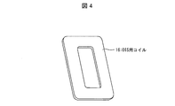
- FIG. 2 is a figure which shows typically schematic structure of the coil for OIS which concerns on Embodiment 1 of this invention.
- Embodiment 1 Hereinafter, an embodiment of the present invention will be described in detail with reference to FIGS. 1A and 1B to FIG.
- a camera module having an optical image stabilization (OIS: Optical Image Stabilizer) function and an autofocus (AF) function will be described as an example.
- OIS optical image stabilization
- AF autofocus
- VCM Vehicle Coil Motor: voice coil motor
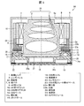
- FIG. 1A is a perspective view schematically showing a schematic configuration of the camera module 50 of the present embodiment.
- the camera module 50 includes an imaging lens unit 3 including an imaging lens 1, a camera shake correction unit 4, an imaging unit 5, and a cover 6.
- the imaging unit 5, the camera shake correction unit 4, and the imaging lens unit 3 are stacked in this order from the imaging unit 5 in the optical axis direction of the imaging lens 1.
- the imaging lens unit 3 side (subject side) will be described as the upper side, and the imaging unit 5 side will be described as the lower side.
- the cover 6 has a box shape that covers the imaging unit 5, the camera shake correction unit 4, and the imaging lens unit 3 from above the imaging lens unit 3.
- An opening 6 a is provided at a position corresponding to the upper side of the imaging lens 1 in the cover 6.
- the inside of the cover 6 may be black that does not reflect light.
- the camera module 50 has a configuration in which the imaging lens unit 3, the camera shake correction unit 4, and the imaging unit 5 are stacked.
- the laminated structure of the camera module 50 will be described with reference to FIG.
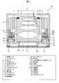
- FIG. 1B schematically shows a schematic configuration of the laminated structure of the imaging lens unit 3, the camera shake correction unit 4 and the imaging unit 5 in the cover 6 in the camera module 50 shown in FIG. It is a side view.
- FIG. 1B shows a state where the cover 6 is removed from the camera module 50 shown in FIG.
- the imaging lens unit 3 includes an optical unit 31 described later. Further, in the peripheral space on the outer side surface of the optical unit 31, an AF coil 9 and an AF magnet 10 are used as an AF drive unit (autofocus drive unit) that drives the imaging lens 1 in the optical axis direction for autofocus. (See FIG. 2) is arranged.
- AF drive unit autofocus drive unit
- the camera shake correction unit 4 includes an OIS movable plate 12, an OIS base 14, a guide ball 15 and the like, which will be described later.
- the optical unit 31 may be disposed so as to protrude into the region of the camera shake correction unit 4.
- the OIS movable plate 12 is provided with an opening 12a described later
- the OIS base 14 is provided with an opening 14a described later.
- a part of optical part 31 is arrange
- the imaging lens unit 3 is placed in a plane perpendicular to the optical axis direction for camera shake correction.
- An OIS magnet 13 and an OIS coil 16 are arranged as an OIS drive section (camera shake correction drive section) to be driven.
- the camera module 50 has a structure in which the imaging lens unit 3, the camera shake correction unit 4, and the imaging unit 5 can be independently arranged. Therefore, various methods can be selected as the autofocus drive mechanism of the imaging lens unit 3 and the camera shake correction drive mechanism of the camera shake correction unit 4.
- the autofocus drive mechanism and the camera shake correction drive mechanism for example, in addition to the VCM method exemplified in this embodiment, a method using a piezoelectric element or a shape memory alloy (SMA), or a shape of a polymer lens is changed. You may select an appropriate method. In addition, it is easy to combine the drive mechanisms of different member manufacturers, and each of the imaging lens unit 3, the camera shake correction unit 4, and the imaging unit 5 can independently consider downsizing and thinning.
- SMA shape memory alloy
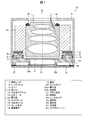
- FIG. 2 is a cross-sectional view taken along the line AA of the camera module 50 shown in FIG. 1A, and is a cross-sectional view of the center portion of the camera module 50 cut along the optical axis direction.
- the imaging lens unit 3 drives the imaging lens 1 in the optical axis direction.
- the imaging lens unit 3 includes an optical unit 31, leaf springs 7 and 8, an AF coil 9, an AF magnet 10, and an AF base 11.
- the optical unit 31 includes a plurality (four in FIG. 2) of imaging lenses 1 and a lens barrel 2.
- the imaging lens 1 guides light from the outside to the imaging element 18 of the imaging unit 5.
- the axis of the image sensor 18 coincides with the optical axis of the imaging lens 1.
- the lens barrel 2 holds a plurality (four in FIG. 2) of imaging lenses 1 therein.
- the axis of the lens barrel 2 also coincides with the optical axis of the imaging lens 1.
- the outer periphery of the lens barrel 2 is provided with a protrusion 2a that protrudes in a direction perpendicular to the optical axis.
- the projecting portion 2 a serves as a mechanical end stopper on the infinity side and a mounting portion of the leaf spring 8.
- the lens barrel 2 has a rectangular parallelepiped shape, but is not limited thereto, and for example, a lens barrel having a cylindrical shape may be used.
- the AF base 11 is a hollow rectangular member, and an AF magnet 10 is fixed on the upper surface.
- the leaf springs 7 and 8 are metal springs that are widely used in existing camera modules with an AF function and whose inner and outer sides are connected by a spiral leaf spring arm.
- the leaf springs 7 and 8 are arranged in pairs at predetermined intervals on the upper and lower portions of the lens barrel 2 so as to surround the lens barrel 2.
- the inner end portion of the leaf spring 7 disposed above is fixed to the upper portion of the lens barrel 2, and the outer end portion of the leaf spring 7 disposed above is the AF magnet. 10 is fixed to the AF base 11 through 10.
- the inner end of the leaf spring 8 disposed below is fixed to the lower portion of the lens barrel 2, and the outer end of the leaf spring 8 disposed below is fixed to the AF base 11.
- the leaf spring applies a downward force to the lens barrel 2, and in a state where no current flows through the AF coil 9, a part (lower end) of the lens barrel 2 is placed in the opening 14 a provided in the central portion of the OIS base 14. Get in.
- the AF coil 9 and the AF magnet 10 function as an AF driving unit.
- the AF coil 9 is disposed and fixed on the outer side surface of the lens barrel 2.
- the AF coil 9 is wound around a square as shown in FIG. 3 so as to surround the lens barrel 2.
- the axis of the AF coil 9 coincides with the optical axis.
- an AF magnet 10 is arranged so as to face each side surface of the AF coil 9 wound in a square shape.
- the AF magnets 10 are arranged so that the same polarity magnetic poles face inward (the same polarity magnetic poles face the AF coil 9).
- the AF base 11 and the AF magnet 10 function as an AF fixing unit whose position does not change during autofocus.
- the optical unit 31 and the AF coil 9 function as an AF movable unit that is movable in the optical axis direction (that is, its position is changed) during autofocus.
- the camera shake correction unit 4 drives the imaging lens unit 3 in a plane perpendicular to the optical axis for camera shake correction.
- the camera shake correction unit 4 includes an OIS movable plate (movable portion) 12, an OIS magnet (permanent magnet, movable portion) 13, an OIS base (fixed portion) 14, a guide ball (guide member) 15, and an OIS coil (coil) 16. , A Hall element 17 and a magnetic body (magnetic body, movable part) 26.
- the OIS movable plate 12 is a flat plate member having an opening 12a into which a part of the lens barrel 2 can be inserted in the optical axis direction, and the AF base 11 is fixed on the upper surface.
- the protrusion 2a of the lens barrel 2 is in contact with the OIS movable plate 12 in a state where no current is passed through the AF coil 9 and gravity is acting downward.
- the bottom surface of the protrusion 2a (the surface facing the OIS movable plate 12) is in contact with the OIS movable plate 12 with the optical unit 31 positioned at the infinity end (mechanical end on the infinity side). Positioning of the imaging lens 1 (determination of the initial position) is performed by positioning the optical unit 31.
- the protrusion 2 a is provided at a position where a part of the lens barrel 2 is disposed in the opening 12 a of the OIS movable plate 12 and the opening 14 a of the OIS base 14 in a state where the protrusion 2 a is in contact with the OIS movable plate 12. .
- a part of the lens barrel 2 includes the opening 12 a of the OIS movable plate 12 and the OIS base 14 in a state where the lens barrel 2 is incorporated in the camera module 50. It has penetrated into the opening 14a.
- the OIS base 14 is a rectangular member having an opening 14a into which a part of the lens barrel 2 can be inserted in the optical axis direction, and an OIS coil 16 and a Hall element 17 are fixed inside.
- the position of the OIS base 14 does not fluctuate both during autofocus and during camera shake correction.
- the guide ball 15 is in sliding contact with the OIS movable plate 12 and supports the OIS movable plate 12 so as to be movable in a plane perpendicular to the optical axis direction with respect to the OIS base 14.
- the material of the guide ball 15 is, for example, ceramic.
- the material of the guide ball 15 is not limited to ceramic, but is preferably a non-magnetic material that is hardly affected by the magnetic field caused by the OIS magnet 13 and the OIS coil 16.
- the hall element 17 detects a displacement in a plane perpendicular to the optical axis direction of the OIS movable plate 12.
- a plurality (usually two in order to detect displacement in two axial directions perpendicular to the optical axis direction) are arranged in the opening of the OIS coil 16.
- the magnetic body 26 is a hollow flat plate member disposed on the upper surface of the OIS base 14 and abuts on the guide ball 15.
- the material may be any material such as iron that generates a magnetic attractive force with the OIS magnet 13.
- the guide ball 15 is prevented from being lifted from the surface of the OIS movable plate 12. Can do. Therefore, according to said structure, the imaging lens part 3 and an OIS movable part can be smoothly moved within the plane perpendicular
- the OIS coil 16 and the OIS magnet 13 function as an OIS drive unit as described above.
- the OIS coil 16 is wound in a donut shape having a substantially oval shape (vertically long in a direction orthogonal to one of two axes orthogonal to the optical axis).
- a plurality of in this embodiment, four in total, one on each side are arranged.
- a plurality of OIS magnets 13 are arranged below the OIS movable plate 12 with different magnetic poles facing the long sides of the OIS coil 16.
- the OIS movable plate 12 and the OIS magnet 13 function as an OIS movable portion that is movable in a direction perpendicular to the optical axis by rolling of the guide ball 15.
- the OIS base 14 and the magnetic body 26 support the guide ball 15, and the positions thereof are not changed by the rolling of the guide ball 15. For this reason, it functions as an OIS fixing part.
- the imaging unit 5 images light that has passed through the imaging lens 1.
- the imaging unit 5 includes an imaging element 18, a substrate 19, a sensor cover 20, and a glass substrate 21.
- the image sensor 18 receives light that has arrived via the imaging lens 1 and performs photoelectric conversion, and obtains a subject image formed on the image sensor 18.
- the front end surface of the protrusion 20b provided in the lower part is in contact with the imaging device 18, and the imaging device 18 covers the entire imaging device 18. Is placed.
- the sensor cover 20 has an opening 20a penetrating in the vertical direction in the center, and the opening 20a is closed by a glass substrate 21 having an IR (Infrared) cut function.
- the image sensor 18 is mounted on the substrate 19. There may be a gap between the substrate 19 and the sensor cover 20 due to tolerances.
- the substrate 19 and the sensor cover 20 are bonded and fixed in a state where the gap is closed by the adhesive 22.
- the AF function for moving the AF movable unit in the optical axis direction is realized by an AF driving unit (AF driving mechanism) including an AF coil 9 and an AF magnet 10.
- the OIS function for moving the imaging lens unit and the OIS movable plate 12 in a plane perpendicular to the optical axis direction is realized by an OIS drive unit (OIS drive mechanism) including the OIS coil 16 and the OIS magnet 13. .
- the Hall element 17 that detects the position of the OIS movable plate 12 with respect to the image sensor 18 is mounted in the camera module 50. Since the hall element 17 can appropriately control the displacement amount and direction of the OIS movable plate 12 according to the amount and direction of camera shake, the correction accuracy of camera shake correction can be improved.
- the camera module 50 excellent in the optical characteristic can be provided.
- the OIS movable plate 12 on which the imaging lens unit 3 is mounted is supported by the guide ball 15. Therefore, there is no need to install a member for fixing the lens portion and the movable portion of the camera shake correction mechanism, such as a suspension wire, outside the imaging lens or the like as in Patent Document 2. Therefore, it is not necessary to provide a mechanism and space for installing the suspension wire, and the camera module 50 can be downsized.
- the imaging lens unit 3 and the OIS movable plate 12 are only supported by the guide balls 15, and a drive mechanism for moving the imaging lens unit 3 and the OIS movable plate 12 is provided. It is not directly linked. Therefore, since the imaging lens unit 3 and the OIS movable plate 12 have a configuration independent from each other, separation is easy, and any lens unit can be used for the imaging lens unit. Therefore, according to the present embodiment, the camera module 50 can be both downsized and thin regardless of the structure of the imaging lens unit 3.
- a part of the lens barrel 2 is disposed in the opening 12a of the OIS movable plate 12 and the opening 14a of the OIS base 14. According to the said structure, the thickness of the camera module 50 can be suppressed by the thickness of the insertion part of the lens barrel 2, and the camera module 50 can be made thinner. Further, the space corresponding to the insertion portion of the lens barrel 2 can be effectively utilized.
- the case where the magnetic body 26 that works with the OIS magnet 13 is provided at the position in contact with the guide ball 15 is described as an example.
- the configuration is not limited to the above as long as the urging force that prevents the guide ball 15 from floating from the surface of the OIS movable plate 12 can be applied to the guide ball 15.
- a spring that applies a biasing force to the guide ball 15 may be provided instead of the magnetic body 26, a spring that applies a biasing force to the guide ball 15 may be provided.
- the imaging lens 1 side is described as the upper side, and the imaging unit 5 side is described as the lower side.
- this does not define the vertical direction during use, and may be upside down, for example.
- FIG. 5 is a cross-sectional view schematically showing a schematic configuration of the camera module 50 according to the present embodiment.
- FIG. 5 corresponds to a cross-sectional view taken along line AA of the camera module 50 shown in FIG.
- the camera module 50 according to the present embodiment is different from the camera module 50 according to the first embodiment in that the OIS movable plate 12 and the AF base 11 are shared.
- the camera module 50 according to the present embodiment includes an OIS movable plate and AF base (movable portion) 23 instead of the OIS movable plate 12 and the AF base 11 in the camera module 50 according to the first embodiment.
- the OIS movable plate / AF base 23 functions as an OIS movable part / AF fixed part.
- the bottom wall of the OIS movable plate / AF base 23 is provided with a recess 23b having an opening 23a penetrating in the vertical direction at the center of the bottom wall.
- the initial position of the lens barrel 2 with respect to the OIS movable plate / AF base 23 is determined by the protrusion 2a coming into contact with the recess 23b.
- the protrusion 2a is in contact with the recess 23b in a state in which no current is passed through the AF coil 9 and gravity is acting downward.
- the optical unit 31 is positioned such that the bottom surface (the surface facing the recess 23b) of the projection 2a contacts the recess 23b in a state where the optical unit 31 is positioned at the infinity end (mechanical end on the infinity side). By positioning, the imaging lens 1 is positioned.
- the protrusion 2a is provided at a position where a part of the lens barrel 2 is disposed in the opening 23a of the OIS movable plate / AF base 23 and the opening 14a of the OIS base 14 in a state of being in contact with the recess 23b. Yes.
- the AF magnet 10 is fixed on the OIS movable plate / AF base 23 so as to face each side surface of the AF coil 9.
- an OIS magnet 13 is arranged below the OIS movable plate / AF base 23 as in the first embodiment.
- the lens barrel 2 is mounted on the OIS movable plate / AF base 23, so that the imaging lens unit 3 is mounted on the OIS movable unit as in the first embodiment. .
- the imaging lens unit 3 mounted on the OIS movable plate / AF base 23 is integrated with the OIS movable plate / AF base 23 by the rolling of the guide ball 15 and is perpendicular to the optical axis direction. Move in a flat plane.
- the present embodiment can provide the same effects as those of the first embodiment.
- the OIS movable plate 12 and the AF base 11 are made common so that the number of parts can be reduced. Further, since space saving is realized, the camera module 50 can be further reduced in thickness.
- FIG. 6 is a cross-sectional view schematically showing a schematic configuration of the camera module 50 according to the present embodiment. 6 corresponds to a cross-sectional view taken along line AA of the camera module 50 shown in FIG.
- the optical unit 31 includes a lens holder 24 that holds the lens barrel 2 in addition to the imaging lens 1 and the lens barrel 2, as shown in FIG.
- the camera module 50 according to the present embodiment includes a lens holder 24 and, instead of the protrusion 2a, a protrusion 24a protruding in a direction perpendicular to the optical axis is provided on the outer periphery of the lens holder 24.
- the camera module 50 according to the second embodiment is different from the camera module 50 according to the second embodiment.
- the protrusion 24a is in contact with the recess 23b in a state where no current is passed through the AF coil 9 and gravity is acting downward. Thereby, in this embodiment, the initial position of the lens holder 24 is determined with respect to the OIS movable plate and AF base 23.
- the lens barrel 2 is fixed to a lens holder 24 mounted on the OIS movable plate / AF base 23 by an adhesive 25 after being adjusted in position in the optical axis direction.
- the two upper and lower leaf springs 7 and 8 support the lens holder 24 so as to be movable in the optical axis direction.
- a part of the lens barrel 2 is disposed in the opening 23 a of the OIS movable plate / AF base 23 and the opening 14 a of the OIS base 14 in a state where the optical unit 31 is located at the infinity end. In position, it is fixed to the lens holder 24.
- the imaging lens unit 3 is mounted on the OIS movable unit as in the second embodiment.
- a part of the lens barrel 2 is disposed in the opening 23 a of the OIS movable plate / AF base 23 and the opening 14 a of the OIS base 14. Therefore, the present embodiment can provide the same effects as those of the second embodiment.
- the lens barrel 2 and the lens holder 24 are provided, and unlike the case where the protrusion 2a is provided, the lens barrel 2 is within the range of the length of the lens holder 24 in the optical axis direction.
- the position adjustment in the optical axis direction can be freely performed to some extent.
- the initial position of the imaging lens 1 in the optical axis direction with respect to the imaging element 18 can be set easily and accurately.
- FIG. 7 is a cross-sectional view schematically showing a schematic configuration of the camera module 50 according to the present embodiment.
- FIG. 7 corresponds to a cross-sectional view taken along line AA of the camera module 50 shown in FIG.
- the camera module 50 includes leaf springs 7 and 8, an AF coil 9, an AF magnet 10, an OIS movable plate / AF base 23, and a protrusion 24a.
- the imaging lens 1 is a fixed focus lens.
- the OIS base 14 has the camera shake correction unit 4 side (more specifically, the opening 20a) in the sensor cover 20 that constitutes a part of the imaging unit 5. On the side). Therefore, the position of the OIS base 14 does not vary with respect to the imaging unit 5 in any case, including during camera shake correction.
- the lens barrel 2 and the lens holder 24 are provided separately, and the lens barrel 2 is fixed to the lens holder 24 with an adhesive 25 after being adjusted in position in the optical axis direction.
- the imaging lens 1 is a fixed focus lens
- the leaf springs 7 and 8, the AF coil 9, and the AF magnet 10 do not exist
- the lens holder 24 also serves as the AF base 11 and the OIS movable plate 12. Yes.
- the lens holder 24 is directly mounted on the OIS magnet 13.
- the lens barrel 2 is placed in the lens holder 24 at a position where a part of the lens barrel 2 is disposed in the opening 14a of the OIS base 14 with the optical unit 31 positioned at the infinity end. Fixed.
- the lens holder 24 is mounted on the OIS magnet 13 so that the imaging lens unit 3 is mounted on the OIS movable unit, as in the third embodiment. Also in this embodiment, a part of the lens barrel 2 is disposed in the opening 14 a of the OIS base 14. Further, in the present embodiment, similarly to the third embodiment, by providing the lens barrel 2 and the lens holder 24, within the range of the length of the lens holder 24 in the optical axis direction, the lens barrel 2 in the optical axis direction can be used. Position adjustment can be performed freely to some extent. Therefore, the present embodiment can provide the same effects as those of the third embodiment.
- the camera shake correction function based on the conventional autofocus camera module can be realized even in a fixed focus camera module.
- the configuration in the direction perpendicular to the optical axis of the imaging lens unit can be simplified, and the camera module 50 can be further downsized.
- the lens holder 24 is mounted on the OIS magnet 13 has been described as an example.
- the present embodiment is not limited to this, and the lens holder 24 may be mounted on the OIS movable plate 12 or the OIS movable plate / AF base 23.
- a projection 2a may be provided on the lens barrel 2, and the projection 2a may be mounted on the OIS movable plate 12 or the OIS movable plate / AF base 23.
- the OIS movable part of the camera module 50 may have the same configuration as that of the first embodiment, for example.
- FIG. 8 is a cross-sectional view schematically showing a schematic configuration of the camera module 50 according to the present embodiment. 8 corresponds to a cross-sectional view taken along line AA of the camera module 50 shown in FIG.
- the camera module 50 according to the present embodiment is different from the camera module 50 according to the second embodiment in that the OIS base 14 and the sensor cover 20 are shared.
- the camera module 50 according to the present embodiment is the same as the camera module 50 according to the second embodiment except that the OIS base 14 is eliminated, and the OIS coil 16 and the displacement detecting Hall element 17 are provided in the sensor cover 20. 13 is embedded at a position facing 13. Accordingly, in the present embodiment, the sensor cover 20 is used as an OIS base / sensor cover (OIS fixing unit / image pickup unit).
- the OIS base 14 is eliminated, and the OIS coil 16 and the Hall element 17 are embedded in the sensor cover 20, so that the lens barrel 2 is in a state where the optical unit 31 is located at the infinity end.
- a part of the lens barrel 2 is fixed to the lens holder 24 at a position where the lens barrel 2 is disposed in the opening 23 a of the OIS movable plate / AF base 23.
- the lens barrel 2 is mounted on the OIS movable plate / AF base 23 as in the second embodiment, so that the imaging lens unit 3 is mounted on the OIS movable unit.
- the second embodiment is the same as the second embodiment in that a part of the lens barrel 2 is disposed in the opening 23 a of the OIS movable plate / AF base 23. Therefore, the present embodiment can provide the same effects as those of the second embodiment.
- the OIS base 14 and the sensor cover 20 are made common so that the number of parts can be reduced. Thereby, since space saving is realized, the camera module 50 can be further reduced in thickness.
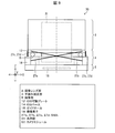
- FIG. 9 is a side view schematically showing a schematic configuration of a main part of the camera module 50 according to the present embodiment. 9 corresponds to a view in which the cover 6 is removed from the camera module 50 shown in FIG.
- the camera module 50 of this embodiment uses Embodiments 1 to 27 in that shape memory alloys (SMA: Shape memory alloy, hereinafter referred to as “SMA”) 27a to 27d are used as the OIS drive section (OIS drive mechanism). 5 different from the camera module 50 according to FIG.
- SMA Shape memory alloys
- the SMAs 27a to 27d are SMA wires (SMA elements) formed in a wire shape, and have a characteristic that they generate heat by themselves when current flows through the elements and contract by the heat. .
- the SMAs 27a and 27b are installed in the OIS movable plate 12 at one end and the OIS base 14 at the other end so that the pair of SMAs 27a and 27b are arranged in an X shape.
- the imaging lens unit 3 contracts by being heated, the imaging lens unit 3 is pulled in the left direction in FIG. 9, and when the SMA 27b contracts, the imaging lens unit 3 is pulled in the right direction in FIG.
- the optical unit 31 moves relative to the image sensor 18 so that optical camera shake correction can be performed.
- a pair of SMAs 27a and 27b may be arranged on the surface of the camera shake correction unit 4 opposite to the surface shown in FIG. 9 (that is, the surface not shown on the back surface side in FIG. 9).
- the imaging lens unit 3 can be linearly displaced in the left-right direction (X direction) in FIG. .
- the imaging lens unit 3 is moved in the Y direction (that is, perpendicular to the paper surface in FIG. 9) out of two directions (X direction and Y direction in FIG. 9) perpendicular to the optical axis direction (Z direction in FIG. 9).
- the SMA 27c and 27d arranged on a surface different from the surface provided with the SMA 27a and 27b may be used.
- the SMAs 27c and 27d are SMA wires (SMA elements) formed in a wire shape like the SMAs 27a and 27b. Similarly to the SMAs 27a and 27b, the SMAs 27c and 27d are each provided with one end on the OIS movable plate 12 and the other end on the OIS base 14 so as to be arranged in a pair of X shapes.
- a total of two pairs of SMAs 27c and 27d may be arranged on the mutually opposing surfaces in the camera shake correction unit 4.
- the imaging lens unit 3 can be linearly displaced in the Y direction.
- the shape memory alloys 27a to 27d can be easily detached from the OIS movable plate 12 and the OIS base 14. Therefore, it is possible to appropriately change only the OIS drive mechanism employed in the camera shake correction unit 4 without changing the AF drive mechanism employed in the imaging lens unit 3.
- the SMAs 27a to 27d are used as the OIS driving unit, it is possible to obtain a large driving force with a smaller electric power than in the case where the VCM is used.
- the camera module (50) includes: An imaging lens unit (3) having an imaging lens (1) and an autofocus driving unit (AF coil 9 and AF magnet 10) for driving the imaging lens in the optical axis direction; An imaging unit (5) having an imaging element (18); A camera shake correction unit that has openings (openings 12a and 14a) facing the image pickup device and moves the image pickup lens unit in a plane perpendicular to the optical axis direction in a state where the image pickup lens faces the image pickup device.
- An imaging lens unit (3) having an imaging lens (1) and an autofocus driving unit (AF coil 9 and AF magnet 10) for driving the imaging lens in the optical axis direction
- An imaging unit (5) having an imaging element (18)
- a camera shake correction unit that has openings (openings 12a and 14a) facing the image pickup device and moves the image pickup lens unit in a plane perpendicular to the optical axis direction in a state where the image pickup lens faces the image pickup device.
- the camera shake correction unit A movable part (for example, OIS movable plate 12, OIS movable plate / AF base 23 or OIS magnet 13) on which the imaging lens unit is mounted; A fixed part (for example, the OIS base 14 and the magnetic body 26) provided on the imaging unit side of the movable part, the position of which does not vary during camera shake correction; A spherical guide member (guide ball 15) provided between the movable part and the fixed part and movably supporting the movable part in a plane perpendicular to the optical axis direction with respect to the fixed part; I have.
- movable part for example, OIS movable plate 12, OIS movable plate / AF base 23 or OIS magnet 13
- a fixed part for example, the OIS base 14 and the magnetic body 26
- the imaging lens unit itself having the imaging lens and the autofocus drive unit moves in the direction perpendicular to the optical axis direction integrally with the movable unit, the entire lens group is in a direction perpendicular to the optical axis direction. Can be moved to.
- the camera module excellent in the optical characteristic can be provided.
- the imaging lens unit and the movable unit are only supported by a spherical guide member, and the imaging lens unit and the drive mechanism for moving the movable unit are not directly connected. Therefore, it is not necessary to provide a mechanism and a space for installing a member for directly connecting the imaging lens unit and the driving mechanism outside the imaging lens, and the camera module can be reduced in size.
- any lens unit can be used as the imaging lens unit, and both downsizing and thinning are achieved regardless of the structure of the imaging lens unit. be able to.
- the camera module (50) includes: An imaging lens section (3) having an imaging lens (1); An imaging unit (5) having an imaging element (18); A camera shake correction unit that has openings (openings 12a and 14a) facing the image pickup device and moves the image pickup lens unit in a plane perpendicular to the optical axis direction in a state where the image pickup lens faces the image pickup device.
- the camera shake correction unit A movable part (for example, the OIS movable plate 12, the OIS movable plate / AF base 23, or the lens holder 24 also serving as the OIS movable plate 12, the OIS magnet 13) on which the imaging lens unit is mounted;
- a fixed part for example, the OIS base 14 and the magnetic body 26
- a spherical guide member guide ball 15
- the imaging lens unit itself moves integrally with the movable unit in the direction perpendicular to the optical axis direction, so that the entire lens group can be moved in the direction perpendicular to the optical axis direction.
- the camera module excellent in the optical characteristic can be provided.
- the imaging lens unit and the movable unit are only supported by a spherical guide member, and the imaging lens unit and the drive mechanism for moving the movable unit are not directly connected. Therefore, it is not necessary to provide a mechanism and a space for installing a member for directly connecting the imaging lens unit and the driving mechanism outside the imaging lens, and the camera module can be reduced in size.
- any lens unit can be used as the imaging lens unit, and both downsizing and thinning are achieved regardless of the structure of the imaging lens unit. be able to.
- the imaging lens unit, the camera shake correction unit, and the imaging unit are stacked, a part of the configuration at the interface of each layer (that is, the imaging lens unit, the camera shake correction unit, and the imaging unit) is used in common. It is also possible to arrange each layer independently. By adopting such a stacked arrangement structure, the imaging lens unit, the camera shake correction unit, and the imaging unit can be configured in various combinations.
- the position of the fixed unit does not vary with respect to the imaging unit in any case, including during camera shake correction.
- the image stabilization lens unit, the camera shake correction unit, and the imaging unit are separated from each other by providing a fixed unit that does not change position in the camera shake correction unit, the imaging lens unit, the camera shake correction unit, and the imaging unit are independent of each other. Can be configured. Therefore, the imaging lens unit, camera shake correction unit, and imaging unit can be configured in various combinations.
- the entire lens group can be moved in a direction perpendicular to the optical axis direction, and the lens or the image sensor is oriented in a direction perpendicular to the optical axis direction. There is no need to separately arrange a camera shake correction device to be moved. Therefore, it is possible to reduce the thickness of a camera module that adopts the fixed focus method.
- a camera module with excellent optical characteristics and a miniaturized camera module can be realized even when the fixed focus method is adopted.
- the imaging lens unit (3) includes a lens barrel (2) that holds the imaging lens (1). May be configured to be disposed in the opening (at least one of the openings 12a and 14a).
- the thickness of the camera module can be suppressed by the thickness of the insertion portion of the lens barrel into the opening, and the space corresponding to the insertion portion of the lens barrel can be effectively utilized. Therefore, the camera module can be further reduced in thickness.
- the imaging lens unit (3) includes a lens holder (24) that holds the lens barrel (2).
- the lens barrel may be fixed to the lens holder at an initial position in the optical axis direction with respect to the imaging element (18) of (1).
- the position of the lens barrel in the optical axis direction can be adjusted to some extent within the range of the length of the lens holder in the optical axis direction. Therefore, the initial position of the imaging lens in the optical axis direction with respect to the imaging element can be easily and accurately set for a camera module with a camera shake correction function that is both compact and thin.
- the camera module (50) according to the fifth aspect of the present invention is the camera module (50) according to any one of the first to fourth aspects, wherein the movable portion (for example, the OIS movable plate 12 or the lens holder 24 that also serves as the OIS movable plate 12) You may comprise a part of imaging lens part (3).
- the movable portion for example, the OIS movable plate 12 or the lens holder 24 that also serves as the OIS movable plate 12
- You may comprise a part of imaging lens part (3).
- the movable part and a part of the imaging lens part are shared, the number of parts can be omitted. Further, it is not necessary to secure a space for arranging the movable part, and the camera module can be further reduced in thickness.
- the camera shake correction unit (4) drives the imaging lens (1) in a plane perpendicular to the optical axis direction. It may be configured to include a camera shake correction driving unit (for example, the OIS magnet 13 and the OIS coil 16 or the SMAs 27a, 27b, 27c, and 27d).
- a camera shake correction driving unit for example, the OIS magnet 13 and the OIS coil 16 or the SMAs 27a, 27b, 27c, and 27d).
- the imaging lens (1) may be a fixed focus lens.
- the camera shake correction function is based on an autofocus camera module, according to the above configuration, it is possible to realize a camera module with a novel structure, that is, a camera module with a camera shake correction function with a fixed focus method.
- the configuration of the imaging lens unit can be simplified in a direction perpendicular to the optical axis direction. Therefore, it is possible to further reduce the size of the camera module.
- the fixing unit (for example, the OIS base 14) may constitute a part of the imaging unit (5). .
- the fixed part and a part of the imaging part are shared, the number of parts can be omitted. Further, it is not necessary to secure a space for arranging the fixing portion, and the camera module can be further reduced in thickness.
- the camera module (50) according to the ninth aspect of the present invention is the camera module (50) according to any one of the first to eighth aspects, wherein the movable portion (for example, the OIS movable plate 12, the OIS movable plate and AF base 23) is the fixed portion (for example, the OIS).
- the imaging lens unit and the movable unit can be smoothly moved in a plane perpendicular to the optical axis direction. Further, since the coil and the guide member are not in direct contact, damage to the coil can be prevented.
- the present invention can be used in a camera module, and in particular, can be suitably used in a camera module mounted on various electronic devices including a communication device such as a portable terminal.
Landscapes
- Physics & Mathematics (AREA)
- Engineering & Computer Science (AREA)
- Multimedia (AREA)
- Signal Processing (AREA)
- General Physics & Mathematics (AREA)
- Optics & Photonics (AREA)
- Chemical & Material Sciences (AREA)
- Power Engineering (AREA)
- Electromagnetism (AREA)
- Combustion & Propulsion (AREA)
- Adjustment Of Camera Lenses (AREA)
- Studio Devices (AREA)
- Lens Barrels (AREA)
Abstract
Priority Applications (3)
| Application Number | Priority Date | Filing Date | Title |
|---|---|---|---|
| US15/110,157 US9723211B2 (en) | 2014-01-10 | 2014-11-21 | Camera module with image stabilization by moving imaging lens |
| CN201480072707.1A CN105900006B (zh) | 2014-01-10 | 2014-11-21 | 摄像机组件 |
| JP2015556722A JP6138969B2 (ja) | 2014-01-10 | 2014-11-21 | カメラモジュール |
Applications Claiming Priority (2)
| Application Number | Priority Date | Filing Date | Title |
|---|---|---|---|
| JP2014003735 | 2014-01-10 | ||
| JP2014-003735 | 2014-01-10 |
Publications (1)
| Publication Number | Publication Date |
|---|---|
| WO2015104908A1 true WO2015104908A1 (fr) | 2015-07-16 |
Family
ID=53523748
Family Applications (1)
| Application Number | Title | Priority Date | Filing Date |
|---|---|---|---|
| PCT/JP2014/080918 Ceased WO2015104908A1 (fr) | 2014-01-10 | 2014-11-21 | Module d'appareil photographique |
Country Status (4)
| Country | Link |
|---|---|
| US (1) | US9723211B2 (fr) |
| JP (1) | JP6138969B2 (fr) |
| CN (1) | CN105900006B (fr) |
| WO (1) | WO2015104908A1 (fr) |
Cited By (16)
| Publication number | Priority date | Publication date | Assignee | Title |
|---|---|---|---|---|
| CN107277305A (zh) * | 2016-04-01 | 2017-10-20 | 台湾东电化股份有限公司 | 摄像模块及其控制方法 |
| CN107277304A (zh) * | 2016-04-01 | 2017-10-20 | 台湾东电化股份有限公司 | 摄像模块及其控制方法 |
| JP2018018083A (ja) * | 2016-07-29 | 2018-02-01 | 台湾東電化股▲ふん▼有限公司 | レンズ駆動装置 |
| CN107664895A (zh) * | 2016-07-29 | 2018-02-06 | 台湾东电化股份有限公司 | 镜头驱动装置 |
| CN107817610A (zh) * | 2016-09-12 | 2018-03-20 | 台湾东电化股份有限公司 | 光学元件驱动机构 |
| JP2018128589A (ja) * | 2017-02-09 | 2018-08-16 | Tdk株式会社 | レンズ駆動装置及び電磁駆動ユニット |
| CN109643026A (zh) * | 2016-08-24 | 2019-04-16 | 哈钦森技术股份有限公司 | 具有光学稳像的双相机组件 |
| KR20190097113A (ko) * | 2016-12-16 | 2019-08-20 | 허친슨 테크놀로지 인코포레이티드 | 광학 이미지 안정화 서스펜션에서의 센서 이동 구조 |
| JP2019159268A (ja) * | 2018-03-16 | 2019-09-19 | オリンパス株式会社 | ブレ補正装置 |
| JP2020027285A (ja) * | 2018-08-09 | 2020-02-20 | エーエーシー テクノロジーズ ピーティーイー リミテッド | レンズモジュール |
| JP2021006846A (ja) * | 2019-06-28 | 2021-01-21 | エーエーシー オプティクス (チャンジョウ)カンパニーリミテッド | レンズ駆動装置 |
| JP2022163541A (ja) * | 2021-04-14 | 2022-10-26 | アルプスアルパイン株式会社 | カメラモジュール駆動装置及び撮像装置 |
| US12007618B2 (en) | 2020-09-02 | 2024-06-11 | Hutchinson Technology Incorporated | Guided autofocus assembly |
| US12147059B2 (en) | 2016-12-16 | 2024-11-19 | Hutchinson Technology Incorporated | Sensor shift structures in optical image stabilization suspensions |
| WO2026058810A1 (fr) * | 2024-09-11 | 2026-03-19 | アルプスアルパイン株式会社 | Dispositif d'entraînement de lentille et module de caméra |
| US12591102B2 (en) | 2020-09-02 | 2026-03-31 | Hutchinson Technology Incorporated | Guided autofocus assembly |
Families Citing this family (33)
| Publication number | Priority date | Publication date | Assignee | Title |
|---|---|---|---|---|
| GB201412848D0 (en) | 2014-07-18 | 2014-09-03 | Cambridge Mechatronics Ltd | Suspension system for a camera lens element |
| JP7040896B2 (ja) | 2016-04-01 | 2022-03-23 | 台湾東電化股▲ふん▼有限公司 | カメラモジュールおよびそれを制御する方法 |
| CN206584105U (zh) * | 2016-04-01 | 2017-10-24 | 台湾东电化股份有限公司 | 镜头驱动机构 |
| US10447931B2 (en) * | 2016-04-01 | 2019-10-15 | Tdk Taiwan Corp. | Camera module having electromagnetic driving assembly |
| TWI618949B (zh) | 2016-04-01 | 2018-03-21 | 台灣東電化股份有限公司 | 鏡頭驅動機構及其控制方法 |
| US9869840B1 (en) * | 2016-06-27 | 2018-01-16 | Ming-Jui LI | Disposable lens applied to electronic operation device for recognition |
| CN106131435B (zh) * | 2016-08-25 | 2021-12-07 | 东莞市亚登电子有限公司 | 微型光学防抖摄像头模组 |
| CN108124092A (zh) * | 2016-11-29 | 2018-06-05 | 宁波舜宇光电信息有限公司 | 基于长宽方向的光学防抖摄像模组及其成像方法和电子设备 |
| US10122924B2 (en) * | 2017-01-23 | 2018-11-06 | Faez Ba-Tis | Camera modules using MEMS micro electrostatic pistontube actuators for autofocus (AF) and optical image stabilization (OIS) |
| JP6869771B2 (ja) * | 2017-03-30 | 2021-05-12 | 日本電産サンキョー株式会社 | 振れ補正機能付き光学ユニット |
| KR102067069B1 (ko) * | 2017-06-16 | 2020-01-16 | 삼성전기주식회사 | 카메라 모듈 |
| KR102584971B1 (ko) | 2018-07-06 | 2023-10-05 | 삼성전기주식회사 | 카메라 모듈 |
| KR102776131B1 (ko) * | 2019-04-11 | 2025-03-07 | 엘지이노텍 주식회사 | 렌즈 구동 장치 |
| JP7025558B2 (ja) * | 2019-06-01 | 2022-02-24 | エーエーシー オプティックス ソリューションズ ピーティーイー リミテッド | オートフォーカスレンズユニット |
| EP3995887A4 (fr) * | 2019-07-01 | 2023-08-09 | LG Innotek Co., Ltd. | Appareil d'entraînement de lentille, module d'appareil photo et dispositif optique les comprenant |
| CN110933266B (zh) * | 2019-07-15 | 2021-12-21 | 华为技术有限公司 | 摄像装置、方法及调节元件 |
| WO2021092856A1 (fr) * | 2019-11-14 | 2021-05-20 | 南昌欧菲光电技术有限公司 | Module de caméra et terminal mobile |
| JP7057516B2 (ja) * | 2019-12-12 | 2022-04-20 | ミツミ電機株式会社 | レンズ駆動装置、カメラモジュール、及びカメラ搭載装置 |
| CN111142309B (zh) * | 2020-01-16 | 2024-05-17 | 睿恩光电有限责任公司 | 压电式光学防抖机构、相机装置及电子设备 |
| WO2021159275A1 (fr) * | 2020-02-11 | 2021-08-19 | Huawei Technologies Co., Ltd. | Appareil pour déplacer une unité de lentille |
| US11743586B2 (en) * | 2020-07-13 | 2023-08-29 | Apple Inc. | Camera actuator with moving coils and dynamic flex circuit |
| CN116349236B (zh) * | 2020-07-15 | 2026-03-31 | 宁波舜宇光电信息有限公司 | 具有云台的摄像模组 |
| CN217156913U (zh) * | 2020-10-22 | 2022-08-09 | 台湾东电化股份有限公司 | 光学元件驱动机构 |
| CN114430455B (zh) | 2020-10-29 | 2025-10-31 | 华为技术有限公司 | 图像传感器防抖组件、摄像装置及电子设备 |
| CN114460788B (zh) * | 2020-11-02 | 2024-08-27 | 阿尔卑斯阿尔派株式会社 | 透镜驱动装置以及相机模块 |
| US12422693B2 (en) | 2020-11-10 | 2025-09-23 | Beijing Xiaomi Mobile Software Co., Ltd. | Optical imaging system, method for performing optical image stabilization |
| CN114520858B (zh) * | 2020-11-19 | 2023-10-13 | 宁波舜宇光电信息有限公司 | 光学防抖摄像模组 |
| WO2022105572A1 (fr) | 2020-11-19 | 2022-05-27 | 宁波舜宇光电信息有限公司 | Module de caméra optique anti-tremblement |
| JP2022097994A (ja) * | 2020-12-21 | 2022-07-01 | ジョウシュウシ レイテック オプトロニクス カンパニーリミテッド | 撮像装置用防振機構、光学系、カメラ及び電子機器 |
| GB2602627B (en) * | 2020-12-31 | 2023-06-07 | Cambridge Mechatronics Ltd | Actuator assemblies |
| CN216718789U (zh) * | 2021-01-08 | 2022-06-10 | 台湾东电化股份有限公司 | 光学元件驱动机构 |
| US12212834B1 (en) | 2021-09-03 | 2025-01-28 | Apple Inc. | Chassis cut-out to improve reliability and performance for cameras including bearing structures |
| US12219255B1 (en) | 2022-09-14 | 2025-02-04 | Apple Inc. | Ball bearing sensor shift arrangement for camera with fixed magnets |
Citations (8)
| Publication number | Priority date | Publication date | Assignee | Title |
|---|---|---|---|---|
| JP2006078881A (ja) * | 2004-09-10 | 2006-03-23 | Sharp Corp | 像ぶれ補正装置およびそれを備える小型携帯端末 |
| JP2008244708A (ja) * | 2007-03-27 | 2008-10-09 | Canon Inc | 撮像装置および携帯機器 |
| JP2011128583A (ja) * | 2009-11-17 | 2011-06-30 | Tdk Taiwan Corp | レンズ駆動装置 |
| JP2012150421A (ja) * | 2011-01-14 | 2012-08-09 | Tdk Taiwan Corp | レンズモジュールの防震装置 |
| JP2013160995A (ja) * | 2012-02-07 | 2013-08-19 | Nidec Copal Corp | レンズ駆動装置 |
| JP2013167860A (ja) * | 2011-08-12 | 2013-08-29 | Sharp Corp | カメラモジュール |
| JP2013186268A (ja) * | 2012-03-07 | 2013-09-19 | Alps Electric Co Ltd | レンズ駆動装置 |
| JP2013195703A (ja) * | 2012-03-19 | 2013-09-30 | Tdk Corp | レンズ駆動装置 |
Family Cites Families (11)
| Publication number | Priority date | Publication date | Assignee | Title |
|---|---|---|---|---|
| CN1113302C (zh) * | 1993-07-30 | 2003-07-02 | 佳能株式会社 | 通过通信线路控制设备的控制器和方法 |
| JPH07131746A (ja) * | 1993-10-29 | 1995-05-19 | Canon Inc | 電子カメラ |
| JP3242515B2 (ja) * | 1993-12-24 | 2001-12-25 | キヤノン株式会社 | 撮像装置 |
| JP4617107B2 (ja) * | 2004-07-09 | 2011-01-19 | キヤノン株式会社 | ズームレンズ及びそれを有する撮像装置 |
| CN100380925C (zh) * | 2004-07-23 | 2008-04-09 | 佳能株式会社 | 摄像机 |
| KR20100109727A (ko) * | 2009-04-01 | 2010-10-11 | 삼성테크윈 주식회사 | 카메라 흔들림 보정 모듈, 이를 구비한 카메라 모듈 및 카메라 모듈 제조방법 |
| JP2013083692A (ja) | 2011-10-06 | 2013-05-09 | Sony Corp | ぶれ補正装置及び撮像装置 |
| KR101940480B1 (ko) * | 2012-06-28 | 2019-01-21 | 엘지이노텍 주식회사 | 카메라 모듈 |
| CN105980921B (zh) * | 2014-02-12 | 2018-12-18 | 富士胶片株式会社 | 摄像模块及电子设备 |
| EP2916153B1 (fr) * | 2014-03-05 | 2021-04-07 | LG Innotek Co., Ltd. | Appareil de déplacement de lentille et module de caméra comprenant celui-ci |
| KR102542645B1 (ko) * | 2015-08-18 | 2023-06-14 | 엘지이노텍 주식회사 | 렌즈구동장치, 카메라 모듈 및 광학기기 |
-
2014
- 2014-11-21 CN CN201480072707.1A patent/CN105900006B/zh not_active Expired - Fee Related
- 2014-11-21 US US15/110,157 patent/US9723211B2/en active Active
- 2014-11-21 WO PCT/JP2014/080918 patent/WO2015104908A1/fr not_active Ceased
- 2014-11-21 JP JP2015556722A patent/JP6138969B2/ja not_active Expired - Fee Related
Patent Citations (8)
| Publication number | Priority date | Publication date | Assignee | Title |
|---|---|---|---|---|
| JP2006078881A (ja) * | 2004-09-10 | 2006-03-23 | Sharp Corp | 像ぶれ補正装置およびそれを備える小型携帯端末 |
| JP2008244708A (ja) * | 2007-03-27 | 2008-10-09 | Canon Inc | 撮像装置および携帯機器 |
| JP2011128583A (ja) * | 2009-11-17 | 2011-06-30 | Tdk Taiwan Corp | レンズ駆動装置 |
| JP2012150421A (ja) * | 2011-01-14 | 2012-08-09 | Tdk Taiwan Corp | レンズモジュールの防震装置 |
| JP2013167860A (ja) * | 2011-08-12 | 2013-08-29 | Sharp Corp | カメラモジュール |
| JP2013160995A (ja) * | 2012-02-07 | 2013-08-19 | Nidec Copal Corp | レンズ駆動装置 |
| JP2013186268A (ja) * | 2012-03-07 | 2013-09-19 | Alps Electric Co Ltd | レンズ駆動装置 |
| JP2013195703A (ja) * | 2012-03-19 | 2013-09-30 | Tdk Corp | レンズ駆動装置 |
Cited By (30)
| Publication number | Priority date | Publication date | Assignee | Title |
|---|---|---|---|---|
| CN107277305B (zh) * | 2016-04-01 | 2020-10-09 | 台湾东电化股份有限公司 | 摄像模块及其控制方法 |
| CN107277304A (zh) * | 2016-04-01 | 2017-10-20 | 台湾东电化股份有限公司 | 摄像模块及其控制方法 |
| US10616487B2 (en) | 2016-04-01 | 2020-04-07 | Tdk Taiwan Corp. | Camera module and method for controlling the same |
| US11516397B2 (en) | 2016-04-01 | 2022-11-29 | Tdk Taiwan Corp. | Camera module and method for controlling the same |
| CN107277305A (zh) * | 2016-04-01 | 2017-10-20 | 台湾东电化股份有限公司 | 摄像模块及其控制方法 |
| JP2018018083A (ja) * | 2016-07-29 | 2018-02-01 | 台湾東電化股▲ふん▼有限公司 | レンズ駆動装置 |
| CN107664895A (zh) * | 2016-07-29 | 2018-02-06 | 台湾东电化股份有限公司 | 镜头驱动装置 |
| CN107664895B (zh) * | 2016-07-29 | 2020-06-09 | 台湾东电化股份有限公司 | 镜头驱动装置 |
| CN109643026A (zh) * | 2016-08-24 | 2019-04-16 | 哈钦森技术股份有限公司 | 具有光学稳像的双相机组件 |
| JP2019526833A (ja) * | 2016-08-24 | 2019-09-19 | ハッチンソン テクノロジー インコーポレイテッドHutchinson Technology Incorporated | 光学画像安定化を伴うデュアルカメラ組立体 |
| EP3504587A4 (fr) * | 2016-08-24 | 2020-04-15 | Hutchinson Technology Incorporated | Ensembles double appareil de prise de vues avec stabilisation d'image optique |
| CN107817610B (zh) * | 2016-09-12 | 2021-02-12 | 台湾东电化股份有限公司 | 光学元件驱动机构 |
| CN107817610A (zh) * | 2016-09-12 | 2018-03-20 | 台湾东电化股份有限公司 | 光学元件驱动机构 |
| KR20190097113A (ko) * | 2016-12-16 | 2019-08-20 | 허친슨 테크놀로지 인코포레이티드 | 광학 이미지 안정화 서스펜션에서의 센서 이동 구조 |
| US12044219B2 (en) | 2016-12-16 | 2024-07-23 | Hutchinson Technology Incorporated | Sensor shift structures in optical image stabilization suspensions |
| US12147059B2 (en) | 2016-12-16 | 2024-11-19 | Hutchinson Technology Incorporated | Sensor shift structures in optical image stabilization suspensions |
| JP2020515881A (ja) * | 2016-12-16 | 2020-05-28 | ハッチンソン テクノロジー インコーポレイテッドHutchinson Technology Incorporated | 光学画像安定化サスペンションにおけるセンサシフト構造 |
| KR102826368B1 (ko) | 2016-12-16 | 2025-06-30 | 허친슨 테크놀로지 인코포레이티드 | 광학 이미지 안정화 서스펜션에서의 센서 이동 구조 |
| KR102507615B1 (ko) * | 2016-12-16 | 2023-03-09 | 허친슨 테크놀로지 인코포레이티드 | 광학 이미지 안정화 서스펜션에서의 센서 이동 구조 |
| KR20230035711A (ko) * | 2016-12-16 | 2023-03-14 | 허친슨 테크놀로지 인코포레이티드 | 광학 이미지 안정화 서스펜션에서의 센서 이동 구조 |
| JP2018128589A (ja) * | 2017-02-09 | 2018-08-16 | Tdk株式会社 | レンズ駆動装置及び電磁駆動ユニット |
| JP2019159268A (ja) * | 2018-03-16 | 2019-09-19 | オリンパス株式会社 | ブレ補正装置 |
| JP2020027285A (ja) * | 2018-08-09 | 2020-02-20 | エーエーシー テクノロジーズ ピーティーイー リミテッド | レンズモジュール |
| US11555979B2 (en) | 2019-06-28 | 2023-01-17 | Aac Optics Solutions Pte. Ltd. | Lens driving device |
| JP2021006846A (ja) * | 2019-06-28 | 2021-01-21 | エーエーシー オプティクス (チャンジョウ)カンパニーリミテッド | レンズ駆動装置 |
| US12007618B2 (en) | 2020-09-02 | 2024-06-11 | Hutchinson Technology Incorporated | Guided autofocus assembly |
| US12591102B2 (en) | 2020-09-02 | 2026-03-31 | Hutchinson Technology Incorporated | Guided autofocus assembly |
| JP2022163541A (ja) * | 2021-04-14 | 2022-10-26 | アルプスアルパイン株式会社 | カメラモジュール駆動装置及び撮像装置 |
| JP7635910B2 (ja) | 2021-04-14 | 2025-02-26 | アルプスアルパイン株式会社 | カメラモジュール駆動装置及び撮像装置 |
| WO2026058810A1 (fr) * | 2024-09-11 | 2026-03-19 | アルプスアルパイン株式会社 | Dispositif d'entraînement de lentille et module de caméra |
Also Published As
| Publication number | Publication date |
|---|---|
| US9723211B2 (en) | 2017-08-01 |
| CN105900006A (zh) | 2016-08-24 |
| US20160330375A1 (en) | 2016-11-10 |
| CN105900006B (zh) | 2018-05-25 |
| JP6138969B2 (ja) | 2017-05-31 |
| JPWO2015104908A1 (ja) | 2017-03-23 |
Similar Documents
| Publication | Publication Date | Title |
|---|---|---|
| JP6138969B2 (ja) | カメラモジュール | |
| JP5606819B2 (ja) | カメラモジュール | |
| CN103901701B (zh) | 透镜驱动装置、摄像模块以及附带摄像机的便携式终端 | |
| CN104423118B (zh) | 透镜驱动装置和包括该透镜驱动装置的相机模块 | |
| CN104977783B (zh) | 相机模块 | |
| JP5926460B2 (ja) | 鏡筒の傾斜制御可能なボイスコイルモータ構造 | |
| US10684532B2 (en) | Lens-driving device, camera module, and camera mount device | |
| JP5765361B2 (ja) | レンズ保持装置 | |
| JP2020112793A (ja) | 光学システム | |
| WO2009142149A1 (fr) | Dispositif d’entraînement de lentille | |
| JP2017508181A (ja) | レンズ駆動モータ | |
| CN104698721A (zh) | 镜头驱动装置 | |
| KR102608087B1 (ko) | 렌즈 구동 장치, 카메라 모듈, 및 카메라 탑재 장치 | |
| CN111788519A (zh) | 镜头致动器 | |
| JP2008287034A (ja) | アクチュエータ、およびその製造方法、撮像機器、ならびに携帯電子機器 | |
| KR20180119595A (ko) | 렌즈 구동 장치, 카메라 모듈, 및 카메라 탑재 장치 | |
| US12483771B2 (en) | Photosensitive chip drive device and camera module | |
| KR101072404B1 (ko) | 요크를 사용하지 않는 카메라 자동초점 조절장치 | |
| CN114531523A (zh) | 光学防抖摄像模组 | |
| CN116261023A (zh) | 防抖摄像模组 | |
| WO2022134191A1 (fr) | Mécanisme anti-vibration pour appareil photographique, système optique, appareil photo et dispositif électronique | |
| KR102029953B1 (ko) | 카메라 모듈 | |
| KR20100124135A (ko) | 이미지 촬상 장치용 렌즈 액츄에이터 | |
| WO2015001954A1 (fr) | Appareil d'entraînement d'objectif | |
| JP5760116B2 (ja) | カメラモジュール |
Legal Events
| Date | Code | Title | Description |
|---|---|---|---|
| 121 | Ep: the epo has been informed by wipo that ep was designated in this application |
Ref document number: 14877864 Country of ref document: EP Kind code of ref document: A1 |
|
| ENP | Entry into the national phase |
Ref document number: 2015556722 Country of ref document: JP Kind code of ref document: A |
|
| WWE | Wipo information: entry into national phase |
Ref document number: 15110157 Country of ref document: US |
|
| NENP | Non-entry into the national phase |
Ref country code: DE |
|
| 122 | Ep: pct application non-entry in european phase |
Ref document number: 14877864 Country of ref document: EP Kind code of ref document: A1 |