WO2015104963A1 - Dispositif de traitement d'image et procédé de transmission d'image mobile - Google Patents
Dispositif de traitement d'image et procédé de transmission d'image mobile Download PDFInfo
- Publication number
- WO2015104963A1 WO2015104963A1 PCT/JP2014/083284 JP2014083284W WO2015104963A1 WO 2015104963 A1 WO2015104963 A1 WO 2015104963A1 JP 2014083284 W JP2014083284 W JP 2014083284W WO 2015104963 A1 WO2015104963 A1 WO 2015104963A1
- Authority
- WO
- WIPO (PCT)
- Prior art keywords
- image
- unit
- complexity
- parameter
- reduced
- Prior art date
- Legal status (The legal status is an assumption and is not a legal conclusion. Google has not performed a legal analysis and makes no representation as to the accuracy of the status listed.)
- Ceased
Links
Images







Classifications
-
- H—ELECTRICITY
- H04—ELECTRIC COMMUNICATION TECHNIQUE
- H04N—PICTORIAL COMMUNICATION, e.g. TELEVISION
- H04N19/00—Methods or arrangements for coding, decoding, compressing or decompressing digital video signals
- H04N19/10—Methods or arrangements for coding, decoding, compressing or decompressing digital video signals using adaptive coding
- H04N19/134—Methods or arrangements for coding, decoding, compressing or decompressing digital video signals using adaptive coding characterised by the element, parameter or criterion affecting or controlling the adaptive coding
- H04N19/136—Incoming video signal characteristics or properties
- H04N19/14—Coding unit complexity, e.g. amount of activity or edge presence estimation
-
- H—ELECTRICITY
- H04—ELECTRIC COMMUNICATION TECHNIQUE
- H04N—PICTORIAL COMMUNICATION, e.g. TELEVISION
- H04N19/00—Methods or arrangements for coding, decoding, compressing or decompressing digital video signals
- H04N19/10—Methods or arrangements for coding, decoding, compressing or decompressing digital video signals using adaptive coding
- H04N19/102—Methods or arrangements for coding, decoding, compressing or decompressing digital video signals using adaptive coding characterised by the element, parameter or selection affected or controlled by the adaptive coding
- H04N19/117—Filters, e.g. for pre-processing or post-processing
-
- H—ELECTRICITY
- H04—ELECTRIC COMMUNICATION TECHNIQUE
- H04N—PICTORIAL COMMUNICATION, e.g. TELEVISION
- H04N19/00—Methods or arrangements for coding, decoding, compressing or decompressing digital video signals
- H04N19/10—Methods or arrangements for coding, decoding, compressing or decompressing digital video signals using adaptive coding
- H04N19/102—Methods or arrangements for coding, decoding, compressing or decompressing digital video signals using adaptive coding characterised by the element, parameter or selection affected or controlled by the adaptive coding
- H04N19/132—Sampling, masking or truncation of coding units, e.g. adaptive resampling, frame skipping, frame interpolation or high-frequency transform coefficient masking
-
- H—ELECTRICITY
- H04—ELECTRIC COMMUNICATION TECHNIQUE
- H04N—PICTORIAL COMMUNICATION, e.g. TELEVISION
- H04N19/00—Methods or arrangements for coding, decoding, compressing or decompressing digital video signals
- H04N19/10—Methods or arrangements for coding, decoding, compressing or decompressing digital video signals using adaptive coding
- H04N19/169—Methods or arrangements for coding, decoding, compressing or decompressing digital video signals using adaptive coding characterised by the coding unit, i.e. the structural portion or semantic portion of the video signal being the object or the subject of the adaptive coding
- H04N19/17—Methods or arrangements for coding, decoding, compressing or decompressing digital video signals using adaptive coding characterised by the coding unit, i.e. the structural portion or semantic portion of the video signal being the object or the subject of the adaptive coding the unit being an image region, e.g. an object
- H04N19/172—Methods or arrangements for coding, decoding, compressing or decompressing digital video signals using adaptive coding characterised by the coding unit, i.e. the structural portion or semantic portion of the video signal being the object or the subject of the adaptive coding the unit being an image region, e.g. an object the region being a picture, frame or field
-
- H—ELECTRICITY
- H04—ELECTRIC COMMUNICATION TECHNIQUE
- H04N—PICTORIAL COMMUNICATION, e.g. TELEVISION
- H04N19/00—Methods or arrangements for coding, decoding, compressing or decompressing digital video signals
- H04N19/46—Embedding additional information in the video signal during the compression process
-
- H—ELECTRICITY
- H04—ELECTRIC COMMUNICATION TECHNIQUE
- H04N—PICTORIAL COMMUNICATION, e.g. TELEVISION
- H04N19/00—Methods or arrangements for coding, decoding, compressing or decompressing digital video signals
- H04N19/50—Methods or arrangements for coding, decoding, compressing or decompressing digital video signals using predictive coding
- H04N19/59—Methods or arrangements for coding, decoding, compressing or decompressing digital video signals using predictive coding involving spatial sub-sampling or interpolation, e.g. alteration of picture size or resolution
Definitions
- the present invention relates to an image processing apparatus and a moving image transmission method, and more particularly to an image processing apparatus and the like that can reproduce a high-quality image on the receiving side even when transmitted in a low band.
- FIG. 20 is a schematic configuration diagram of an image transmission system having a general image processing apparatus. As shown in FIG. 20, the image transmission system includes a video encoder 1 as a configuration on the transmission side, and a video decoder 2 and a super-resolution processing unit 3 as a configuration on the reception side.
- the video encoder 1 on the transmission side encodes an image input from an image input device such as a CCD camera using an encoding method such as H.264, and outputs it to a transmission path such as an IP network or a coaxial cable network.
- the video decoder 2 on the receiving side decodes the image data received via the transmission path by a method corresponding to the encoding method in the video encoder 1.
- the super-resolution processing unit 3 performs super-resolution processing for obtaining a higher-resolution image from the decoded image and sets it as an output image.
- the information handled by the moving image coding includes information (moving image information) that handles the pixels themselves constituting the screen, information (header information) that describes how to handle the moving image information, and motion used for inter-screen prediction. It consists of a combination of vector information.
- Patent Document 1 when the compression unit of the video encoding device performs conversion conversion and quantization after reducing and converting the prediction error signal, the quantization coefficient data is generated and reduced. In addition, it is described that the quantized coefficient data is inversely quantized and inversely transformed, and then subjected to expansion transformation to generate a decoded prediction error signal.
- Patent Document 2 in an image compression / decompression method, an area other than an area designated as an important area is converted into reduced data, and the important area and the reduced data are rearranged in an image area that matches the horizontal width of the important area.
- Reduced image data is generated, motion compensation prediction and encoding processing are performed, and at the time of restoration, after decompression processing, the original arrangement is restored based on the header information, and the reduced data is subjected to interpolation processing to obtain an image It describes restoring data.
- JVT Joint Video Team
- Patent Document 1 and Patent Document 2 on the compression side, the complexity of the input image is calculated as the transmission-side complexity, and the cut-off frequency of the low-pass filter and the scaling factor of the reduction unit are calculated according to the transmission-side complexity.
- the encoded stream and the transmission-side complexity are transmitted, and the decompression side compares the complexity of the decoded image with the complexity of the received transmission image so that the difference between the two is minimized.
- the present invention has been made in view of the above circumstances, and an object thereof is to provide an image processing apparatus capable of obtaining a high-quality image even in a situation where fine adjustment cannot be performed by a conventional video encoder.
- an image processing apparatus includes an image compression unit that compresses an input image, and an image expansion unit that decompresses and outputs the compressed image.
- a low-pass filter that limits the band of the received image signal at a set cutoff frequency
- an image reduction unit that reduces the output signal from the low-pass filter according to a set reduction factor, and a band-limited and reduced image signal.
- An encoding unit, a first complexity calculation unit that calculates a first parameter indicating the complexity of the image for the input image signal, and an optimal cutoff frequency based on the first parameter.
- a first control unit that sets an optimal reduction coefficient in the image reduction unit and a first parameter in the encoded stream output from the encoding unit are set in the low-pass filter.
- a demultiplexer that extracts the encoded stream and the first parameter from the input signal, a decoding unit that decodes the encoded stream, and a decoding unit
- An image enlarging unit for enlarging an output signal from the image according to a specified enlarging factor, a super-resolution processing unit that performs super-resolution processing on the enlarged image using a specified aliasing frequency, and an enlarged image
- a second complexity calculation unit that calculates a second parameter indicating the complexity of the image, a complexity comparison unit that calculates a difference or ratio between the first parameter and the second parameter, and the difference or ratio
- a parameter calculation unit that sets an optimum enlargement coefficient in the image enlargement unit and sets an optimum aliasing frequency in the super-resolution processing unit.
- an image processing apparatus including an image compression unit that compresses an input image, and an image expansion unit that decompresses and outputs the compressed image.
- a low-pass filter that band-limits the input image signal at a set cutoff frequency
- an image reduction unit that reduces an output signal from the low-pass filter according to a set reduction factor
- a band-limited reduced image corresponds to the combination of the encoder that encodes the signal, the demultiplexer that extracts the quantization parameter that indicates the degree of information loss from the signal output from the encoder, and the parameter that indicates the complexity and the quantization parameter
- a first complexity table processing unit that outputs a feedback value corresponding to one parameter and the extracted quantization parameter; and an optimum cutoff frequency is set in the low-pass filter based on the feedback value, and an optimum A demultiplexer for extracting the encoded stream and the quantization parameter from the input signal
- An image enlarging unit for enlarging the output signal from the decoding unit according to a set enlarging coefficient, a super-resolution processing unit for performing super-resolution processing using a specified aliasing frequency, and a parameter indicating complexity And a table for storing enlargement coefficients corresponding to the combination of the quantization parameter and the image enlarged by the image enlargement unit.
- a second complexity table processing unit that calculates a second parameter indicating the length and outputs an expansion coefficient corresponding to the second parameter and the extracted quantization parameter based on the table; And a parameter calculation unit that sets an optimal aliasing frequency in the super-resolution processing unit based on the enlargement coefficient.
- the image processing apparatus in the image compression unit, if the image enlargement unit is less than the first threshold set in advance, the entire frame If the image is reduced and if it is equal to or greater than the first threshold value, the entire frame is not reduced, and each of the regions obtained by dividing the input image by the encoding unit regardless of whether the entire frame is reduced or not.
- the region is reduced and encoded. If the parameter is less than a preset second threshold value and the parameter is less than a preset second threshold value, the region is reduced and encoded. If the parameter is equal to or greater than the second threshold value, The image is encoded without being reduced, and in the image expansion unit, the decoding unit performs decoding for each region depending on whether or not the entire frame is reduced in the image compression unit and whether or not each region is reduced. It is a feature.
- the image compression unit and the image expansion unit cooperate with each other according to the complexity of the image, so that an optimal reduction / enlargement process and super Resolution processing can be performed, and a high-quality output image can be reproduced even when transmitted in a low band.
- the optimum reduction / enlargement processing and superimposition according to the complexity of the image can be performed without transmitting parameters from the image compression unit.
- Resolution processing can be performed, and a high-quality output image can be reproduced even when transmitted in a low band.
- the amount of header information can be reduced and the compression rate of moving images can be improved by combining the reduction of the entire frame and the reduction of the motion vector in accordance with the complexity of the image. There is an effect that can.
- FIG. 1 is a configuration block diagram of an image processing apparatus according to Embodiment 1 of the present invention.
- FIG. 6 is a block diagram illustrating a configuration of an image processing apparatus according to a second embodiment of the present invention.
- FIG. 5 is a schematic explanatory diagram illustrating a frame reduction process according to image complexity.
- FIG. 6 is a schematic explanatory diagram illustrating a motion vector associated with image reduction.
- FIG. 6 is a schematic explanatory diagram illustrating transform quantization of a reduced image.
- 10 is a flowchart illustrating processing in an encoding processing unit of a third image processing apparatus.
- the flowchart which shows the complexity area search process of an image The flowchart (1) which shows the image coding process shown to process S4 of FIG.
- Flowchart (2) showing the reduced image encoding process shown in the process S3 of FIG. 10 is a flowchart showing an outline of processing in a decoding processing unit of the third image processing apparatus.
- Explanatory drawing which shows the example of the image size processed with the 3rd image processing apparatus. 1 is a schematic configuration diagram of an image transmission system having a general image processing apparatus.
- the image processing apparatus and the image processing method calculate the image complexity for the input image in the transmission side apparatus, and the calculation result (transmission image complexity) is compressed into the compressed image stream.
- the receiving side apparatus compares the received transmission image complexity with the complexity calculated for the decoded image (decoded image complexity), and based on the comparison result, the scaling parameter and super solution of the image expansion processing are compared.
- Optimize the aliasing frequency parameters for image processing As described above, the image processing apparatus on the transmission / reception side performs a cooperative operation, and can perform appropriate scaling processing and super-resolution processing according to the complexity of the image, thereby obtaining a high-quality output image.
- the image processing apparatus calculates the complexity of the image in the transmission side apparatus, extracts the quantization parameter of the encoding process from the compressed image stream, and uses the complexity and the quantization parameter. Accordingly, the pass band of the low-pass filter and the scaling parameter in the image compression process are appropriately set, and the reception side apparatus extracts the quantization parameter from the received signal, and the scaling parameter for the image expansion process according to the quantization parameter and It optimizes the parameters of super-resolution processing, and the image processing device on the transmission / reception side can perform cooperative operations to perform appropriate scaling processing and super-resolution processing according to the complexity of the image. An output image with high image quality can be obtained.
- FIG. 1 is a block diagram showing the configuration of an image processing apparatus according to Embodiment 1 of the present invention.
- the image processing apparatus (first image processing apparatus) according to the first embodiment has a configuration similar to that of the image processing system illustrated in FIG. 20 including the video encoder 1, the video decoder 2, and the super-resolution processing unit 3. That is, the upper side in FIG. 1 corresponds to the video encoder 1 in FIG. 20, and the lower side corresponds to the video decoder 2 and the super-resolution processing unit 3 in FIG.
- the video decoder includes a super-resolution processing unit.
- the video encoder corresponds to the image compression unit described in the claims, and the video decoder corresponds to the image expansion unit.
- the video encoder includes an image input IF unit 200, a low-pass filter 201, an image reduction unit 202, an encoding unit 212, a complexity calculation unit 203, a multiplexer 204, and a control unit 211.
- the video decoder also includes a demultiplexer 215, a decoding unit 216, an image enlargement unit 217, a complexity calculation unit 218, a complexity comparison unit 219, a parameter calculation unit 220, and a super-resolution processing unit 221. It has.
- the image input IF unit 200 is an interface for acquiring image data from an imaging device such as a CCD camera or a sensor.
- the input format of the image data is an HD-SDI (High Definition Serial Digital Interface) format or the like.
- the low pass filter 201 limits the band of the input image signal from the image input IF unit 200 by cutting a component having a specific frequency (cutoff frequency) or higher.
- the cutoff frequency is set by an instruction from the control unit 211. Note that the low-pass filter 201 does not have a function of changing the image size of the image data.
- the image reduction unit 202 reduces the image size of the input image data.
- the image size is reduced according to the scaling coefficient set by the control unit 211.
- the scaling factor set in the image reduction unit 202 corresponds to the reduction factor described in the claims.
- the encoding unit 212 encodes the input image data for each N ⁇ M pixel block using an H.264 or H.265 encoding method (N and M are integers of 2 or more).
- the encoding unit 212 is a general encoder and is assumed to be capable of setting only an image size and a transmission bit rate and cannot perform internal fine adjustment.
- the encoding unit 212 to which the transmission bit rate is set internally controls the quantization parameter and the like to generate and output an encoded stream with the rate as a target. It should be noted that the application of a complete CBR (Constant BitRate) is rare in applications for transmitting surveillance camera images.
- the moving picture encoding method is not limited to H.264 or the like, and any technique that reduces the data amount up to the transmission band in order to transmit the image data may be used.
- the complexity calculation unit 203 calculates the complexity of the input image and outputs a parameter indicating the complexity (transmission image complexity).
- a parameter indicating the complexity transmission image complexity
- Activity indicating the total sum of the differences between the average value of the pixel values in the block and each pixel value is used.
- the complexity calculation unit 203 divides the input image into basic block units of M ⁇ N pixels, and calculates a pixel average value (Average) for each basic block using (Expression 1).
- the absolute value (difference absolute value) of the difference between the calculated average value (Average) and the value of each pixel in the basic block is obtained, and the sum of the absolute values (difference absolute value sum) is calculated as Activity ( Formula 2).
- Activity takes a large value when the basic block image is complex, and takes a small value when it is simple.
- the complexity calculation unit 203 parameterizes the calculated activity, and outputs the complexity (transmission image complexity), which is a parameter representing the complexity, to the control unit 211 and the multiplexer 204.
- the transmission image complexity corresponds to the first parameter recited in the claims.
- the unit for outputting the transmission image complexity may be a basic block, a slice that is a set of basic blocks, or a frame.
- the parameterization process includes, for example, a method in which the activity range is divided into 256 stages (areas) and the 1-byte data (0-255) is used as it is, and in which code area the calculated activity is included. There is a method of making a determination with reference to and encoding into a shorter bit string.
- the multiplexer 204 multiplexes the complexity input from the complexity calculation unit 203 with the encoded stream and outputs the multiplexed stream to the transmission path.
- the multiplexer 204 since a SEI (Super Enhancement Information) area where the user can freely multiplex information is secured, the multiplexer 204 multiplexes the transmission image complexity in the SEI area of the encoded stream and outputs it. . If a plurality of transmission image complexities are multiplexed together into SEI, an arithmetic code such as Range Coder or a run length code can be applied.
- the control unit 211 stores in advance values of a scaling coefficient and a cutoff frequency corresponding to the transmission image complexity. Based on the input transmission image complexity and the transmission bit rate, the scaling coefficient in the image reduction unit 202 and the cut-off frequency in the low-pass filter 201 are determined and set. This control is specific when the transmission bit rate set in the encoding unit 212 is lower than a predetermined value and / or when the input image is complicated.
- the control unit 211 when the complexity of the input image is within a normal range, the control unit 211 considers that the complexity represents the number of high-frequency components, and decreases the scaling coefficient as the complexity decreases (that is, decreases the complexity).
- the cut-off frequency is lowered in proportion to the scaling factor. Note that components above the cut-off frequency are weakened but remain in the encoded image, and this moderate residual aliasing (folding distortion) is useful for super-resolution processing.
- the cut-off frequency in the low-pass filter 201 is set low to cut the high-frequency component greatly, and the scaling factor for the image reduction processing unit 202 is slightly increased, Performs reduction that eliminates aliasing almost completely.
- the image may not be reduced (the scaling coefficient is set to 1) in order to make super resolution unnecessary.
- the cutoff frequency and scaling factor at this time are called a special cutoff frequency and scaling factor. In this way, the scaling factor and the cut-off frequency can change discontinuously at the predetermined value.
- an image is transmitted in a low band by appropriately setting a cutoff frequency and a scaling factor for image reduction according to the complexity of the input image. Even so, the receiving side can output a high-resolution image.
- the demultiplexer 215 receives the multiplexed transmission stream from the transmission path, separates it into the encoded stream and the transmission image complexity, outputs the encoded stream to the decoding unit 216, and increases the complexity of the transmission image complexity. To the comparator 219.
- the decoding unit 216 decodes the input encoded stream by a decoding method corresponding to the encoding method on the encoder side.
- a general H.264 decoder is assumed.
- the image enlargement unit 217 enlarges the decoded image data according to the scaling coefficient designated by the parameter calculation unit 220. Note that the scaling coefficient set in the image enlargement unit 217 or its inverse corresponds to the enlargement coefficient recited in the claims.
- the complexity calculation unit 218 calculates the complexity for each reference block for the image data expanded to the original size, and outputs the decoded image complexity as a parameter representing the complexity of the decoded image.
- the decoded image complexity corresponds to the second parameter recited in the claims.
- the complexity calculation process and the parameterization process are the same as those in the video encoder complexity calculation unit 218 described above.
- the complexity comparison unit 219 compares the transmission image complexity output from the demultiplexer 215 with the decoded image complexity calculated by the complexity calculation unit 218 on the video decoder side, and calculates the difference or ratio between the two. . That is, the complexity comparison unit 219 changes (deteriorates) the complexity of the input image by the processing and transmission of the low-pass filter 201, the image reduction unit 202, and the image encoding unit 212 in the video encoder on the transmission side. This is to detect whether or not.
- the parameter calculation unit 220 inputs a difference or ratio (here, a difference) between the transmission image complexity and the decoded image complexity output from the complexity comparison unit 219, and based on the difference, for example, the difference is
- a difference or ratio here, a difference
- the optimum scaling coefficient in the image enlargement unit 217 and the optimum folding frequency in the super-resolution processing unit 210 are determined so as to be minimized, and are output to the image enlargement unit 217 and the super-resolution processing unit 210, respectively.
- control is performed so that the value of the ratio approaches 1. That is, the parameter calculation unit 220 controls the image enlargement unit 217 and the super-resolution processing unit 210 so that the complexity of the input image degraded by the processing on the transmission side can be reproduced as much as possible.
- the parameter calculation unit 220 stores a threshold value for determining whether or not the transmission side has been reduced based on the difference in complexity.
- the initial value (1) of the scaling coefficient is given to the image enlargement unit 217.
- the scaling coefficient is Is output to the image enlargement unit 217, and the corresponding folding frequency is output to the super-resolution processing unit 221.
- the scaling coefficient is made larger than 1 and the folding frequency is lowered so as to be inversely proportional to it as the threshold is increased. This process can be repeated until the difference converges below a threshold.
- the folding frequency and the scaling factor are the above-described special cutoff frequency and scaling. Set to the one corresponding to the coefficient.
- the parameter calculation unit 220 may store a scaling coefficient corresponding to the difference in complexity as a table, or may calculate using a calculation formula.
- the scaling coefficient needs to be the same as the scaling parameter applied by the image reduction unit 202 on the video encoder side. Note that the folding frequency can be uniquely determined according to the scaling factor, and even if it is mistaken, there is no fatal effect.
- the image enlargement unit 217 enlarges the image size to the same size as the original image on the transmission side, and the super-resolution processing unit 221 appropriately removes the aliasing component by the super-resolution processing to restore the high-frequency component. And a high-resolution image can be reproduced.
- the image enlargement unit 217 enlarges the input image with the scaling coefficient set from the parameter calculation unit 220.
- the super-resolution processor 221 removes the aliasing component based on the aliasing frequency set by the parameter calculator 220, performs super-resolution processing, and outputs a high-resolution reproduced image.
- the super-resolution processing unit 221 basically tries to restore a component at or above the folding frequency from the component at or below the set folding frequency.
- the parameter calculation unit 220 basically sets the same frequency as the cutoff frequency of the low-pass filter 201 in the super-resolution processing unit 221 as a parameter.
- the cutoff frequency of the low-pass filter 201 or a scaling coefficient that can uniquely identify the low-pass filter 201 should be transmitted from the encoder side together with the complexity or instead of the complexity.
- the image data input from the image input IF unit 200 is branched into two, one of which is a high-frequency filter with a cutoff frequency corresponding to the complexity of the image in a low-pass filter 201.
- the components are cut and reduced by the image reduction unit 202 with a scaling factor corresponding to the complexity of the image.
- the reduced image is encoded by the encoding unit 212 and input to the multiplexer 204 as an encoded stream.
- the transmission image complexity which is a parameter corresponding to the complexity of the image, is calculated in the complexity calculation unit 203, and the transmission image complexity is transmitted to the control unit 211 and the multiplexer 204. Entered.
- control unit 211 sets optimum values for the cutoff frequency of the low-pass filter 201 and the scaling coefficient of the image reduction unit 202 based on the transmission image complexity. At this time, the cut-off frequency and the scaling coefficient are appropriately adjusted so as to suppress the deterioration of the image quality even when transmitted in a low band.
- the encoded stream and the transmission image complexity are multiplexed and output to the transmission path.
- the data received from the transmission path is separated into the encoded stream and the transmission image complexity by the demultiplexer 215, and the encoded stream is decoded by the decoding unit 216,
- the enlargement unit 217 enlarges the image with an optimal scaling factor.
- the complexity calculation unit 218 calculates the complexity of the image from the enlarged image, and outputs the decoded image complexity as a parameter.
- the complexity comparison unit 219 compares the transmission image complexity separated from the received signal with the decoded image complexity calculated on the decoding side, and outputs the difference between the two.
- the scaling coefficient of the image enlargement unit 217 is calculated according to the complexity difference, the aliasing frequency of the super-resolution processing unit 221 is specified accordingly, and the image enlargement unit 217, It is set in the resolution unit 221.
- optimal parameters are set in the image enlarging unit 217 and the super-resolution unit 221 so that the complexity of the original image deteriorated by the processing on the transmission side can be reproduced as much as possible.
- the super-resolution unit 221 performs super-image processing based on the folding frequency from the parameter calculation unit 220 and outputs a high-definition image.
- the unit for multiplexing the transmission image complexity (that is, the unit for switching the scaling coefficient) is one frame (picture) or a slice in H.264, the implementation of this example is easy.
- the unit to be multiplexed is a basic block, it can be applied if the scaling coefficient is limited with respect to the color difference component (that is, as a change in color format), or can be applied only to a picture that does not perform motion compensation.
- the complexity calculator 203 calculates the transmission image complexity as a parameter of the complexity of the input image, and the multiplexer 204
- the transmission image complexity is multiplexed on the encoded stream that has been reduced and encoded, and is output to the transmission line.
- the cut-off frequency of the low-pass filter 201 and the scaling factor in the image reduction unit 202 are set according to the transmission image complexity.
- the demultiplexer 215 extracts the transmission image complexity from the encoded stream, the decoding unit 216 decodes the encoded stream, the image enlarging unit 217 expands with an appropriate scaling factor,
- the complexity calculation unit 218 has a decoded image complexity that is a complexity parameter for the enlarged image.
- the complexity comparison unit 219 compares the transmission image complexity and the decoded image complexity, and outputs the difference or ratio.
- the parameter calculation unit 220 calculates the image based on the complexity difference or ratio.
- the scaling factor of the enlargement unit 216 and the aliasing frequency of the super-resolution processing unit 221 are optimized and set, the image enlargement unit 216 enlarges the image with the set scaling factor, and the super-resolution processing unit 221 is set.
- the super-resolution processing is performed by removing the aliasing component based on the aliasing frequency, and the image processing device on the transmission side and the image processing device on the reception side perform a cooperative operation, depending on the complexity of the image. Appropriate scaling processing and super-resolution processing can be performed, and there is an effect that a high-quality output image can be reproduced even when transmitted in a low band.
- the image processing apparatus (second image processing apparatus) according to the second embodiment of the present invention achieves high image quality on the receiving side without transmitting parameter information indicating complexity from the image processing apparatus on the transmitting side. It can be done.
- FIG. 2 is a block diagram of the configuration of the image processing apparatus according to the second embodiment of the present invention.
- the video encoder of the second image processing apparatus includes an image input IF unit 300, a low-pass filter 301, an image reduction unit 302, and an encoding unit similar to the first image processing apparatus. And a complexity table processing unit 303, a demultiplexer 304, and a control unit 311 as characteristic parts of the second image processing apparatus.
- the video decoder of the second image processing device includes a decoding unit 316, an image enlargement unit 317, a parameter calculation unit 320, a super-resolution processing unit 321, and the same parts as the first image processing device.
- the demultiplexer 304 of the video encoder receives the encoded stream output from the encoding unit 312 and extracts the quantization parameter from the encoded stream.
- the quantization parameter is a parameter used in an encoding scheme such as H.264, and indicates how much information is lost due to encoding.
- the quantization parameter is large, the width of the quantization step is large, the information amount of the image data is greatly reduced, and the image quality is greatly deteriorated. Conversely, when the quantization parameter is small, the image quality degradation is small.
- the complexity table processing unit 303 calculates complexity, which is a parameter representing the complexity of the input image. For example, the complexity calculation method is calculated based on the activity described in the first image processing apparatus. Furthermore, as a feature of the second image processing apparatus, the complexity table processing unit 303 includes a table that outputs a feedback value with the quantization parameter and the complexity as arguments, and the quantization input from the demultiplexer 304 A feedback value is output to the control unit 311 based on the parameter and the calculated complexity. The feedback value only needs to be associated with the scaling coefficient in the image reduction unit 302, and may be, for example, the scaling coefficient itself.
- the quantization parameter indicates how much information is lost in the video encoder.
- the cause of the information loss is that there are two cases, one is because each image is dense, and the other is due to intense movement. There is a street.
- the quantization parameter is large even though the image is small and complex, there is no inconvenience in image reproduction even if the scaling factor is reduced. It is set. As a result, the overhead of the header and the like can be surely reduced as much as the image is reduced, and the motion search range can be widened, which may improve the motion compensation accuracy.
- the control unit 311 stores a cutoff frequency and a scaling factor corresponding to the feedback value, sets an appropriate cutoff frequency in the low-pass filter 301 based on the input feedback value, and sets the scaling factor to the image reduction unit 302. Set to.
- the feedback value may be used as a scaling factor as it is.
- the cut-off frequency in the low-pass filter 301 is lowered to greatly cut the high-frequency component so that the image quality degradation does not increase
- a scaling coefficient is set to be large, and control is performed to suppress image quality deterioration due to compression processing. That is, control is performed so that the quantization parameter becomes small.
- the video encoder side of the second image processing apparatus sets an appropriate scaling factor and cut-off frequency according to the complexity of the input image and the loss state of the information amount in the encoding, and the image in the low band. Even if it is transmitted, a high-resolution image can be restored on the receiving side.
- the unit by which the demultiplexer 304 acquires the quantization parameter and the unit by which the control unit 311 sets the scaling coefficient and the like may be any of a basic block, a slice, and a frame.
- the scaling factor and the cut-off frequency should be applied to an image that will obtain a quantization parameter sufficiently correlated with the obtained quantization parameter. It is.
- the complexity table processing unit 303 can obtain one quantization parameter that represents a plurality of quantization parameters for the latest one frame and use it as an argument of the table. If an encoding unit that does not dynamically control the quantization parameter in the frame is used, the quantization parameter acquired within one frame in the encoding order may be used as it is.
- the demultiplexer 315 on the video decoder side extracts a quantization parameter from the encoded stream received from the transmission path.
- the complexity table processing unit 319 calculates complexity representing the complexity of the decoded image enlarged by the image enlargement unit 317.
- the complexity calculation method is the same as that of the complexity table processing unit 303 on the video encoder side.
- the complexity table processing unit 319 includes a table that stores control values corresponding to the complexity and the quantization parameter, and corresponds to the calculated complexity and the quantization parameter input from the demultiplexer 315.
- the control value to be output is output to the parameter calculation unit 320.
- the control value only needs to be associated with the scaling coefficient in the image enlargement unit 317.
- the control value may be the scaling coefficient itself.
- the parameter calculation unit 320 sets an optimal scaling factor for the image enlargement unit 317 according to the input control value, and sets an optimal folding frequency for the super-resolution processing unit 320.
- the input control value should be based on a quantization parameter strictly corresponding to the image itself to which the set scaling coefficient or the like is applied. That is, the complexity table processing unit 319 does not need to hold the quantization parameter of the previous frame in accordance with the processing on the encoder side, and may provide the parameter calculation unit 320 with a control value based on the current quantization parameter. .
- the complexity table processing unit 303 calculates the complexity based on the input image, refers to the table based on the complexity and the quantization parameter, determines the scaling coefficient of the image reduction unit 302 as a corresponding feedback value, Input to the control unit 311.
- the control unit 311 sets a scaling coefficient in the image reduction unit 302 and sets a cutoff frequency corresponding to the scaling coefficient in the low-pass filter 301.
- the second image processing apparatus by appropriately setting the scaling coefficient and the cut-off frequency on the encoder side, it is possible to perform transmission in a low band and suppress deterioration in image quality.
- the received data is decoded, enlarged, and input to the super-resolution processing unit 321 and the complexity table processing unit 319. Further, the quantization parameter extracted from the received data is input to the complexity table processing unit 319.
- the complexity table processing unit 319 calculates the complexity of the enlarged decoded image, refers to the table based on the complexity and the quantization parameter, determines the scaling coefficient of the image enlargement unit 317 as a control value, The scaling coefficient is output to the parameter calculation unit 320.
- the input scaling coefficient is set in the image enlargement unit 317, and the aliasing frequency corresponding to the scaling coefficient is set in the super-resolution processing unit 321. Then, the super-resolution unit 321 performs super-image processing based on the input folding frequency and outputs a high-definition image.
- the demultiplexer 304 extracts the quantization parameter from the encoded stream, and the complexity table processing unit 303 performs the complexity of the input image.
- the degree is calculated, and the scaling factor of the image reduction unit 302 is determined based on the complexity and the quantization parameter, and is output to the control unit 311.
- the control unit 311 outputs the input scaling factor to the image reduction unit 302. And the cutoff frequency corresponding to the scaling coefficient is set in the low-pass filter 301.
- the demultiplexer 315 extracts the quantization parameter from the input encoded stream, and the complexity table processing unit 319 calculates the complexity of the decoded and enlarged image, and the complexity Based on the quantization parameter, the scaling coefficient of the image enlargement unit 317 is determined and output to the parameter calculation unit 320, and the parameter calculation unit 320 sets the input scaling coefficient in the image enlargement unit 317 and The aliasing frequency corresponding to the coefficient is set in the super-resolution processing unit 320, and the image processing apparatus on the transmission side and the image processing apparatus on the reception side perform a cooperative operation, and an appropriate value is determined according to the complexity of the image. Scaling processing and super-resolution processing can be performed, and there is an effect that a high-quality output image can be reproduced even when transmitted in a low band.
- the third image processing apparatus considers an encoding method for performing motion compensation, and can be implemented alone or in combination with the first and second image processing apparatuses.
- the third image processing apparatus is intended to reduce header information caused by macroblocks by reducing the image on the encoder side and reducing the total number of macroblocks in the frame. This is common with the embodiment.
- FIG. 3 is a schematic explanatory view showing a frame reduction process according to the complexity of the image
- FIG. 4 is a schematic explanatory view showing a motion vector accompanying the image reduction.
- the size of the motion vector is reduced when the image is reduced.
- the motion vector a difference from a prediction vector using surrounding motion vectors is used.
- the difference vector can also be reduced, and the code amount of the motion vector can be reduced.
- the third image processing apparatus reduces the header information and the motion vector information by reducing the image according to the complexity of the image.
- a combination of the reduction of the entire frame and the reduction of the motion vector is appropriately selected according to the complexity of the image, and the compression rate is improved without deteriorating the quality of the reproduced image. .
- FIG. 5 is a block diagram illustrating the configuration of the encoding processing unit of the third image processing apparatus
- FIG. 6 is a block diagram illustrating the configuration of the decoding processing unit of the third image processing apparatus.
- the third image processing apparatus has been studied by stepping into the encoding and decoding processes, and is a kind of two-pass that temporarily encodes both the original image and the reduced image (quantization of transform coefficients). It has an encoding configuration.
- the encoding processing unit of the third image processing apparatus includes an image complex region searching unit 11, an image reducing unit 12, a reduced image region dividing unit 13, an image region dividing unit 14, Reduced image motion search unit 15, motion search unit 16, transform / quantization unit 17, reduced image transform / quantization unit 18, motion vector mode selection unit 19, variable length coding unit 20, and inverse transform / An inverse quantization unit 21, a reconstructed image generation unit 22, a frame memory 23, an image reduction unit 24, and an image enlargement unit 25 are provided.
- the image complex area search unit 11, the image reduction unit 12, the reduced image motion search unit 15, the reduced image conversion / quantization unit 18, and the motion vector mode selection unit 19 are the third. This is a characteristic part of the image processing apparatus. 19
- the image complex area search unit 11 determines the presence or absence of a complex area for each frame of the input image.
- the complexity of the image is determined using an evaluation value such as a frequency distribution after Fourier transform, an average value of pixel values of the image, and a sum of absolute differences (Activity) of the pixel values of each pixel. Note that the calculated complexity may be used for control in motion vector mode selection, image reduction, and the like.
- the input image is complicated, it is output to the image region dividing unit 14 without reducing the entire frame as in the conventional case. If it is determined that the input image is not complicated, the frame is The image is output to the image reduction unit 12 that reduces the entire image.
- the image reduction unit 12 reduces the image in units of frames based on a predetermined method.
- the scaling coefficient of the image reduction unit 12 is set by the control unit 211 in FIG. 1 or the control unit 311 in FIG.
- the reduced image area dividing unit 13 divides an image reduced in units of frames into units of macro blocks (for example, 16 pixels in the vertical direction ⁇ 16 pixels in the horizontal direction), and outputs the unit for each macro block.
- the image region dividing unit 14 divides an unreduced image into macroblock units. Note that the macroblocks output from the reduced image region dividing unit 13 and the macroblocks output from the image region dividing unit 14 have the same image size, but when compared with the same original data, the reduced image region dividing unit 13 The number of macro blocks output from is reduced.
- the reduced image motion search unit 15 reduces the input macroblock, searches the reference image for a location in a region similar to the target image, and calculates a difference image that is a difference from the reference image and the reduced motion. Outputs vector and reference image information.
- the reduced image motion search unit 15 inputs a macroblock (16 pixels in the vertical direction ⁇ 16 pixels in the horizontal direction) of the image whose frame has been reduced from the reduced image region dividing unit 13, and the frame is not reduced from the image region dividing unit 14.
- An image macroblock (16 vertical pixels ⁇ 16 horizontal pixels) is input.
- the reduced image motion search unit 15 reduces the input macroblock to generate a reduced macroblock (8 vertical pixels ⁇ 8 horizontal pixels).
- the reduced image motion search unit 15 acquires a reference image from the frame memory 23. At this time, if the corresponding reference image is reduced, the reference image is not reduced. If the corresponding reference image is not reduced, the reduced reference image is acquired via the image reduction unit 24.
- the reduced image motion search unit 15 searches for a location of an area similar to the target image in the reference image by a technique such as block matching.
- SAD Sum of Absolute Difference
- SSD Sum of Square Difference
- the reduced image motion search unit 15 outputs the reduced motion vector (reduced motion vector) to the motion vector mode selection unit 19 as a result of the motion search, and calculates the difference image between the target image and the reference image, and the reference image.
- the information is transmitted to the reduced image conversion / quantization unit 18.
- the motion search unit 16 searches the reference image for the location of an area similar to the target image for the macroblock that is not reduced, and transmits the difference image, the motion vector, and the reference image information that are the differences from the reference image.
- the motion search unit 16 inputs a macroblock of an image whose frame has been reduced from the reduced image region dividing unit 13 and inputs a macroblock of an image whose frame is not reduced from the image region dividing unit 14. All input macroblocks are 16 pixels long ⁇ 16 pixels wide.
- the motion search unit 16 enlarges the corresponding reference image from the frame memory 23 through the image enlargement unit 25 when the reference image is reduced, and does not enlarge the reference image when the reference image is not reduced. Receive a reference image. Then, the motion search unit 16 searches for a location of a region similar to the target image in the reference image by a method such as block matching, detects a motion vector, and sends the motion vector to the motion vector mode selection unit 19. And the difference image of the reference image and the information of the reference image are transmitted to the conversion / quantization unit 17.
- the reduced image transform / quantization unit 18 inputs a difference image for an image whose region has been reduced, performs a transform such as DCT (Discrete Cosine ⁇ Transform), etc., and quantizes the transform coefficient.
- the input difference image is transmitted to the motion vector mode selection unit 19.
- FIG. 7 is a schematic explanatory diagram illustrating transform quantization of a reduced image.
- conversion quantum is performed by 4 pixels vertically by 4 pixels horizontally.
- quantized transform coefficients of 4 vertical pixels ⁇ 4 horizontal pixels are calculated. This is substituted into a quantized transform coefficient matrix of 8 vertical pixels ⁇ 8 horizontal pixels.
- the substitution position is a region A in FIG.
- the transform / quantization unit 17 receives the difference image of the region that is not reduced from the motion search unit 16, and performs transform such as DCT and quantization of transform coefficients.
- the quantized transform coefficient and the input difference image are transmitted to the motion vector mode selection unit 19.
- the motion vector mode selection unit 19 determines whether or not to reduce the motion vector for each region, and outputs a reduced motion vector or a motion vector that is not reduced as motion vector information. Specifically, the motion vector mode selection unit 19 receives the motion vector and the reduced motion vector from the motion search unit 16 and the reduced image motion search unit 15 respectively, and the transform / quantization unit 17 and the reduced image conversion / quantization unit. 18, each quantized transform coefficient and difference image are input.
- the motion vector mode selection unit 19 uses a reduced motion vector or a motion vector that is not reduced for the region. Judging.
- the determination of the presence or absence of reduction is based on whether the number of transform coefficients after quantization in an unreduced region exceeds a preset threshold value, or in the state of transform coefficients after quantization shown in FIG. Judgment is made by using either or both of the conversion coefficients in region B being zero. This determination method may use other methods.
- the motion vector mode selection unit 19 selects the reduced motion vector as the motion vector information, and the conversion output from the reduced image conversion / quantization unit 18 The coefficient and the reference image information are transmitted to the variable length coding unit 20.
- the motion vector, the transform coefficient output from the transform / quantization unit 17, and reference image information are transmitted to the variable length coding unit 20.
- the motion vector mode selection unit 19 performs inverse conversion on the conversion coefficient of the image whose area is not reduced and the information of the reference image, or the conversion coefficient of the image whose area is reduced and the information of the reference image. / Output to inverse quantization unit 21.
- the variable length encoding unit 29 encodes the motion vector information (motion vector or reduced motion vector) from the motion vector mode selection unit 19 and the quantized transform coefficient by a predetermined variable length encoding method, Superimpose on the output stream.
- the variable length encoding unit 20 encodes and superimposes various header information based on the set information. Image size information indicating the image size of the frame is included in the header.
- the inverse transform inverse / quantization unit 21 performs inverse quantization and inverse transform using the quantized transform coefficient transmitted from the motion vector mode selection unit 19 to generate a reconstructed difference image. Then, the reconstructed difference image and reference image are transmitted to the reconstructed image generation unit 22. At this time, if the quantized transform coefficient is the quantized transform coefficient shown in FIG. 6 and the transform coefficient in region B is 0, the region A in FIG. And 4 ⁇ 4 inverse transform and inverse quantization are performed. As a result, an area of the reduced difference image is generated. When the transform coefficient of the region B is not 0, inverse 8 ⁇ vertical 8 transform and inverse quantization are performed. Thereby, a region of the difference image that is not reduced is generated.
- the reconstructed image generation unit 22 generates a reconstructed image using the reconstructed difference image and reference image, and writes the reconstructed image in a corresponding position in the frame memory. That is, a reduced area and a non-reduced area are mixedly written in the frame memory 23 as a reconstructed image.
- the image reduction unit 24 reduces the image input from the frame memory 23.
- the image enlargement unit 25 enlarges the image input from the frame memory 23.
- FIG. 6 is a configuration block diagram of a decoding processing unit of the third image processing apparatus.
- the decoding processing unit of the third image processing apparatus includes a variable length decoding unit 31, an image size determination unit 32, an inverse transform / inverse quantization unit 33, and a motion vector mode determination unit. 34, a motion compensation unit 35, an image enlargement unit 36, a reconstructed image enlargement unit 37, a frame memory 38, and a reference image enlargement / reduction unit 39.
- the image size determination unit 32, the motion vector mode determination unit 34, the image enlargement unit 36, the reconstructed image enlargement unit 37, and the reference image enlargement / reduction unit 39 are characteristic portions of the third image processing apparatus. It has become.
- variable length decoding unit 31 performs variable length decoding on the input encoded stream, and outputs quantized transform coefficients and header information.
- the image size determination unit 32 transmits the quantized transform coefficient information to the inverse transform / inverse quantization unit 33, extracts the image size information of the corresponding frame, determines the image size, and the motion vector mode determination unit 34. Transmits image size determination information indicating whether or not the corresponding frame has been reduced.
- the motion vector mode determination unit 34 extracts motion vector information based on the quantized coefficient output from the variable length decoding unit 31, determines whether or not the motion vector is reduced, and outputs the motion vector determination information. .
- the motion vector mode determination unit 34 receives the quantized transform coefficient and motion vector information of the corresponding macroblock from the variable length coding 31 and acquires the image size determination information of the corresponding frame from the image size determination unit 32.
- the motion vector mode determination unit 34 calculates the number of quantized transform coefficients as an evaluation value, and the evaluation value is smaller than a preset threshold value or the quantized transform in the region B in FIG. Based on whether all the coefficients are 0, it is determined whether the motion compensation processing is performed with or without reducing the image, and is output as motion vector determination information. Then, the motion vector mode determination unit 34 transmits the motion vector determination information and the image size determination information to the motion compensation unit 35 and the reference image enlargement / reduction unit 39.
- the motion compensation unit 35 extracts a reference area from the reference image according to the motion vector or reduced motion vector acquired as the motion vector information, takes a pixel sum with the reconstructed difference image, and generates a reconstructed image. In addition, the motion compensation unit 35 specifies an enlargement rate according to the image size determination information and the motion vector determination information, and transmits the specified enlargement rate to the reconstructed image enlargement unit 37 and the image enlargement unit 36.
- the image enlargement unit 36 enlarges and outputs the reconstructed image transmitted from the motion compensation unit 35 in accordance with the enlargement ratio transmitted from the motion compensation unit 35.
- the reconstructed image enlargement unit 37 enlarges the reconstructed image in accordance with the enlargement ratio transmitted from the motion compensation unit 35 and writes it to the frame memory 38.
- the reference image enlargement / reduction unit 39 determines the enlargement / reduction rate of the image extracted from the frame memory 38 according to the image size determination information and the motion vector determination information from the motion vector mode determination unit 34, and enlarges / reduces the image. carry out.
- the enlarged / reduced reference image is transmitted to the motion compensation unit 35.
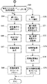
- FIG. 8 is a flowchart showing processing in the encoding processing unit of the third image processing apparatus.
- the complex region search unit 11 of the image performs a complex region search process of the image (S1).
- the output evaluation value is compared with the set threshold value (S2). If the evaluation value is smaller than the set threshold value, the reduced image encoding process (S3) is performed. If it is greater than or equal to the threshold value, the image encoding process (S4) is performed.
- the threshold value in the process of FIG. 8 corresponds to the first threshold value in the claims. The reduced image encoding process and the image encoding process will be described later.
- the encoding processing unit performs variable length encoding in the variable length encoding unit 20 using information on the result of the reduced image encoding process or the image encoding process (S5), and outputs an encoded stream. In this way, the entire operation of the encoding processing unit is performed.
- a motion vector is determined for each area where motion compensation is performed according to the complexity of the area. In order to improve the compression ratio as a whole, it is selected whether to reduce or not. Each process will be described later.
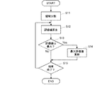
- FIG. 9 is a flowchart showing the complex region search process of an image.
- the image complex area search unit 11 divides the input image of one frame into, for example, areas of 16 pixels vertically and 16 pixels horizontally (S11). Then, the complex region search processing unit 11 of the image obtains an evaluation value for each divided region by using the frequency distribution after Fourier transform, the average value of the pixel values of the image, and the sum of absolute differences of the pixel values of each pixel. Calculate (S12).
- the complex region search unit 11 of the image compares the calculated evaluation value with the maximum value (maximum evaluation value) of the already calculated and stored evaluation values to determine whether the calculated evaluation value is the maximum. Is determined (S13). When it is the maximum, the maximum evaluation value is updated with the calculated evaluation value (S14).
- the complex region search unit 11 of the image determines whether or not the calculation of the evaluation value and the comparison with the maximum evaluation value are all finished for the region to be searched (S15). The process proceeds to step S12 to extract the next area and execute the same process. If the process has been completed for all areas in process S15, the complex area search for the image is terminated.
- the evaluation value stored as the maximum evaluation value at the end of the process becomes the evaluation value indicating the complexity of the image of each frame, and the process S2 shown in FIG. It is to be compared with the threshold value.
- FIGS. 10 and 11 are flowcharts showing the image encoding process shown in the process S4 of FIG.
- the image encoding process is performed when no reduction is performed in units of frames, and the processes shown in FIGS. 10 and 11 are continuously performed.
- the image region dividing unit 14 divides the frame image into regions of macro blocks (vertical 16 pixels ⁇ horizontal 16 pixels) (S21).
- the image region dividing unit 14 performs a flow for reducing the region image and a flow for not reducing in parallel in order to determine whether or not to reduce the motion vector. To do. Therefore, in FIG. 5, the image region dividing unit 14 outputs the divided region images to both the reduced image motion search unit 15 and the motion search unit 16.
- the motion search unit 16 checks whether or not the reference image is reduced (S22). In the case of Yes, the reference image is enlarged and acquired by the image enlargement unit 25 (S23). If the image is not reduced (No), the reference image is used as it is.
- the motion search unit 16 performs block matching using the reference image and the target image divided into regions, and extracts a region similar to the target image.
- a difference between the position of the extracted area and the area of the target image is detected as a motion vector (S24).
- an image based on a difference value of each pixel between the extracted area and the target image area is generated as a difference image.
- the size of the difference image is 16 pixels long ⁇ 16 pixels wide.
- the transform / quantization unit 17 performs transform quantization on the difference image, outputs the quantized transform coefficient (S25), and proceeds to processing (A).
- the reduced image motion search unit 15 inputs the area image that is not reduced from the image area dividing unit 14 and reduces the area image (S26). ). Then, the reduced image motion search unit 15 checks whether or not the reference area has been reduced (S27). If the reference region has not been reduced (No), the reduced image motion search unit 15 reduces the reference image via the image reduction unit 24. (S28). If the image is reduced (Yes), it is used as a reference image as it is.
- the reduced image motion search unit 15 extracts a region similar to the target image in the reference image as the reduced image motion search, and detects a difference between the position of the extracted region and the region of the target image as a reduced motion vector ( S29).
- a reduced motion vector S29
- an image based on a difference value of each pixel between the extracted area and the target image area is generated as a difference image.
- the size of the difference image is 8 pixels long ⁇ 8 pixels wide.
- the reduced image transform / quantization unit 18 performs transform quantization on the difference image, calculates a quantized transform coefficient, and proceeds to the processing (A). Thereby, with respect to an image that is not reduced in the entire frame, a conversion coefficient when the motion vector is not reduced and when the motion vector is reduced is calculated and output to the motion vector mode selection unit 19.
- the motion vector mode selection unit 19 selects an evaluation value (motion vector mode selection evaluation value for selecting a motion vector mode). ) To determine whether to select a reduced motion vector or a non-reduced motion vector.
- the motion vector mode selection unit 19 determines whether the number of quantized transform coefficients of the flow that does not reduce the region is the motion vector mode selection evaluation value, and is smaller than the threshold value (S31).
- the threshold value in the process S31 corresponds to the second threshold value in the claims.
- the motion vector mode selection unit 19 selects the no reduction mode (S32), and the transform / quantization unit 17 The quantized transform coefficient without reduction from is output (S33).
- the inverse transform / inverse quantization unit 21 performs inverse quantization / inverse transform using the output result of transform quantization (S34), and generates a reconstructed difference image (S35).
- the reconstructed image generation unit 22 generates a reconstructed image from the reconstructed difference image and the reference image generated by the image motion search unit 16 (S35), and the generated reconstructed image is stored in the frame memory. 23 (S36), and the process is terminated.
- the reconstructed image stored here is a reference image that is not reduced (vertical 16 pixels ⁇ horizontal 16 pixels).
- the motion vector mode selection unit 19 selects the reduction mode (S37), and the reduced image conversion / quantum
- the reduced quantized transform coefficient from the conversion unit 18 is output (S38).
- the reduced image inverse transform / inverse quantization is performed using the reduced quantized transform coefficient (S39), and the reconstructed image generation unit 22 generates a reconstructed image (S40) and enlarges it (S40).
- S41 the data is stored in the frame memory (S42), and the process is terminated.
- a reduced reference image (8 vertical pixels ⁇ 8 horizontal pixels) is obtained. In this way, the image encoding process is performed when the entire frame is not reduced.
- FIGS. 12 and 13 are flowcharts showing the reduced image encoding process shown in the process S3 of FIG.
- the reduced image encoding process is performed when reduction is performed in units of frames, and the processes shown in FIGS. 12 and 13 are continuously performed.
- the reduced image encoding process has the same basic flow as the image encoding process shown in FIGS. 10 and 11, and therefore only different parts will be described.
- the image reduction unit 12 reduces the input image in units of frames (S51).
- the reduced image region dividing unit 13 divides the reduced image into macroblocks (16 vertical pixels ⁇ 16 horizontal pixels) (S52), the flow that does not reduce the motion vector (does not reduce the region), and the motion vector
- the flow of reducing (reducing the area) is performed in parallel. That is, in FIG. 5, the reduced image region dividing unit 13 outputs the image of the divided region to both the reduced image motion search unit 15 and the motion search unit 16.
- the area of 16 pixels vertically ⁇ 16 pixels horizontally divided by the reduced image area dividing unit 13 corresponds to a 32 ⁇ 32 area in the original image before frame reduction.
- the motion search unit 16 checks whether or not the reference image has been reduced (S53). If the reference image has not been reduced (No), the image reduction unit 24 is checked. The reference image reduced to 16 pixels vertically ⁇ 16 pixels horizontally is acquired (S54). If the image has been reduced, the reference image is used as it is.
- the motion search unit 16 performs block matching using the reference image and the region-divided target image, extracts a region similar to the target image, and performs an image motion search that detects a difference between both positions as a motion vector.
- S55 A difference image is generated.
- the transform / quantization unit 17 performs transform quantization on the difference image, calculates a quantized transform coefficient (S56), and proceeds to processing (B).
- the reduced image motion search unit 15 reduces the input region image (S57).
- the target area for motion search is reduced in frame units, and the area is further reduced in size.
- the reduced image motion search unit 15 checks whether or not the reference image has been reduced (S58). If the reference image has been reduced, the image reduction unit 24 performs the reference image reduction A and then acquires the reference image ( S59), the process proceeds to process 61.
- the reference image reduction A is a process of reducing the vertical and horizontal directions to 1 ⁇ 2. If it is determined in step S58 that the reference image has not been reduced, the image reduction unit 24 performs reference image reduction B, and the process proceeds to step 61.
- Reference image reduction B is a process of reducing the vertical and horizontal dimensions to 1/4.
- the reduced image motion search unit 15 compares the target image having the same size with the reference image, performs block matching, extracts a region similar to the target image from the reference image, and detects a reduced motion vector.
- a reduced image motion search is performed (S61), and an image based on a difference value between each pixel in the extracted area and the target image area is generated as a difference image.
- the reduced image transform / quantization unit 18 performs transform quantization on the difference image, calculates a quantized transform coefficient (S62), and proceeds to the process (B).
- the motion vector mode selection unit 19 calculates a motion vector mode selection evaluation value. Compared with the threshold value (S63), if the motion vector mode selection evaluation value is equal to or greater than the threshold value (in the case of No), the no reduction mode is selected (S64) and is less than the threshold value. If yes (Yes), the reduction mode is selected (S70).
- the reference image obtained by the reduced image encoding process is a reduced reference image.
- the encoding processing unit determines whether or not the entire frame has been reduced according to the complexity of the image in units of frames, and each of the cases when the entire frame is reduced and not moved Depending on the complexity of the macroblock that is the unit of compensation, it is determined whether to reduce the motion vector, that is, the macroblock, and perform appropriate coding for each region to reduce the output image. It is possible to improve the compression rate while suppressing.
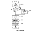
- FIG. 14 is a flowchart illustrating an outline of processing in the decoding processing unit of the third image processing apparatus.
- the decoding processing unit first, the stream to which the variable length decoding unit 31 is input is subjected to variable length decoding (S100), and the image size determination unit 32 receives the frame input from the header information or the like. To determine whether or not the frame is reduced (S110).
- the motion vector mode determination unit 34 determines whether or not the motion vector is reduced (S120), and when the motion vector is not reduced. In the case of No, the decryption processing unit proceeds to decryption process A (S130). If the motion vector is reduced (Yes) in process S120, the decoding processing unit proceeds to decoding process B (S140).
- the motion vector mode determination unit 34 determines whether or not the motion vector is reduced (S150). ), The decryption processing unit proceeds to decryption process C (S160). In the process 150, when the motion vector is reduced (Yes), the decoding processing unit proceeds to the decoding process D (S170). That is, in the decoding processing unit of the third image processing apparatus, four types of decoding processing are performed according to the presence or absence of frame-based reduction and the presence or absence of motion vector reduction.
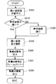
- FIG. 15 is a flowchart of the decoding process A shown in the process S130 of FIG.
- the decoding process A is a decoding process of an area where the entire frame is not reduced and the motion vector is not reduced.
- the inverse transform / inverse quantization unit 33 performs an inverse transform / inverse quantization process to generate a reconstructed difference image (S200). Then, the motion compensation unit 35 determines whether or not the reference image to be referred to for inter-screen prediction is reduced (S210). If the reference image is reduced (in the case of Yes), the reference image enlargement / reduction unit 39 enlarges the reference image (S220). If the image is not reduced (No), the reference image is used as it is.
- the motion compensation unit 35 performs a motion compensation process using the corresponding region of the reference image using the unreduced motion vector extracted by the variable length decoding unit 31 (S230), A reconstructed image is generated based on the pixel sum.
- the reconstructed image is stored in the frame memory 38 as a reference image (S240), and finally the reconstructed image is output (S250).
- a reference image that is not reduced is obtained. In this way, the decoding process A is performed.
- FIG. 16 is a flowchart of the decoding process B shown in the process S140 of FIG.
- the decoding process B is a decoding process of an area in which the entire frame is not reduced and the motion vector is reduced.
- the inverse transform / inverse quantization unit 33 performs reduced inverse transform / inverse quantization to generate a difference image of the reduced area (S300). Specifically, in the reduced inverse transform / inverse quantization, the part of the region A in FIG. 7 is extracted from the transform coefficient of 8 vertical pixels ⁇ 8 horizontal pixels, and the inverse transform and inverse quantization of 4 vertical pixels ⁇ 4 horizontal pixels are performed. To implement. As a result, a reconstructed difference image that has been reduced (for example, vertical 8 pixels ⁇ horizontal 8 pixels) is generated.
- the motion compensation unit 35 determines whether or not the reference image is reduced (S310). If the reference image is not reduced (No), the reference image enlargement / reduction unit 39 reduces the reference image (S320). ). If the image has been reduced (if Yes), the reference image is used as it is. Then, the motion compensation unit 35 uses the reduced motion vector extracted from the variable length decoding unit 31 and performs a reduced image motion compensation process for performing motion compensation on the reduced image using the corresponding region of the reference image (S330). ), A reconstructed image is generated by pixel sum with the reconstructed difference image.
- the reconstructed image enlargement unit 37 enlarges the reconstructed image (S340) and stores it in the frame memory (S350). Thereby, a reference image that is not reduced is obtained.
- the motion compensation unit 35 outputs the reconstructed image to the image enlargement unit 36, and the image enlargement unit 36 enlarges the reconstructed image to the original size and outputs the enlarged reconstructed image (S360). In this way, the decoding process B is performed.
- FIG. 17 is a flowchart of the decoding process C shown in the process S160 of FIG.
- the decoding process C is a decoding process of an area where the entire frame is reduced and the motion vector is not reduced.
- the inverse transform / inverse quantization unit 33 performs an inverse transform / inverse quantization process to generate a reconstructed difference image (S400). Then, the motion compensation unit 35 determines whether or not the reference image referred to for inter-screen prediction has been reduced (S410). If the reference image has not been reduced (No), the reference image enlargement / reduction unit 39 reduces the reference image (S420). If the image has been reduced (if Yes), the reference image is used as it is.
- the motion compensation unit 35 performs a motion compensation process using the corresponding region of the reference image using the unreduced motion vector extracted by the variable length decoding unit 31 (S430), and reconstructed difference image A reconstructed image is generated with the pixel sum.
- the decoding process C is performed.
- FIG. 18 is a flowchart of the decoding process B shown in the process S170 of FIG.
- the decoding process D is a decoding process for an area in which the entire frame is reduced and the motion vector is reduced.
- the inverse transform / inverse quantization unit 33 performs reduced inverse transform / inverse quantization to generate a difference image of the reduced region (S500).
- the reduced inverse transform / inverse quantization performs inverse transform and inverse quantization of vertical 4 pixels ⁇ horizontal 4 pixels from coefficients of vertical 8 pixels ⁇ horizontal 8 pixels, as in the decoding process B of FIG.
- a reconstructed difference image reduced to, for example, 8 vertical pixels ⁇ 8 horizontal pixels is generated.
- the motion compensation unit 35 determines whether or not the reference image has been reduced (S510). If the reference image has been reduced (Yes), the reference image enlargement / reduction unit 39 performs the reference image reduction process A. Thus, the reference image is reduced (S520).
- the reference image reduction process A is a process for reducing the vertical and horizontal halves.
- the reference image enlargement / reduction unit 39 reduces the reference image by the reference image reduction processing B (S530).
- the reference image reduction process B is a process for reducing the image to 1/4 in the vertical and horizontal directions.
- the motion compensation unit 35 performs a reduced image motion compensation process using the corresponding region of the reference image using the reduced motion vector extracted by the variable length decoding unit 31 (S540), A reconstructed image is generated with the pixel sum of.
- the reconstructed image enlargement unit 37 enlarges the reconstructed image (S550) and stores it in the frame memory (S560).
- the motion compensation unit 35 outputs the reconstructed image to the image enlargement unit 36, and the image enlargement unit 36 enlarges the reconstructed image to the original size and outputs the enlarged reconstructed image (S570). In this way, the decoding process D is performed.
- FIG. 19 is an explanatory diagram illustrating an example of an image size processed by the third image processing apparatus.
- FIG. 19 shows how the image size changes depending on the combination of whether or not the entire frame is reduced and whether or not the motion vector is reduced in the processing in the encoding processing unit.
- the macroblock (MB) size is the size of an area divided by the image area dividing unit 14 or the reduced image area dividing unit 13, and in either case, the vertical 16 pixels ⁇ horizontal 16 pixels It has become.
- the size at the time of MC indicates the size of an area when the motion search unit 16 or the reduced motion search unit 15 performs a motion search process such as block matching.
- MC Motion Compensation
- the reduced image motion search unit 15 processes the input macroblock after reducing the size of the input macroblock to 8 pixels ⁇ 8 pixels.
- the size of the original image is the original size of the macroblock, which is the same as the macroblock size when the frame is not reduced (vertical 16 pixels ⁇ horizontal 16 pixels), and when the frame is reduced, It becomes 32 vertical pixels x 32 horizontal pixels.
- the reconstructed difference image is the size of the image reconstructed by the reconstructed image generation unit 22, and when motion vector reduction is performed, the vertical 8 pixels ⁇ horizontal 8 pixels regardless of the presence or absence of frame reduction. It becomes.
- the size of the reference image stored in the frame memory and the size of the reference image at the time of reading when the read reference image is not reduced in the reduced image motion search unit 15 or the motion search unit 16 are described. It shows.
- the size of the reference image stored in the frame memory and the reference at the time of reading are read. It shows the size of the image.
- the motion vector is read after being enlarged / reduced to 16 pixels ⁇ 16 pixels, and if the motion vector is reduced, it is 8 pixels vertically. ⁇ Reduced to 8 horizontal pixels and read.
- the encoding processing unit calculates an evaluation value of complexity for each frame, and if the evaluation value is less than the first threshold value, If the value is equal to or greater than the threshold value, the entire frame is not reduced. Further, the reduced or unreduced frame is divided into regions of a predetermined size, and a motion vector indicating the complexity of the region A mode selection evaluation value is calculated, and if the motion vector mode selection evaluation value is less than the second threshold value, the motion vector is reduced.
- the decoding processing unit appropriately selects from four types of decoding processing for each region according to the combination of the presence / absence of the entire frame reduction and the presence / absence of the reduction of the motion vector. Select the appropriate process Therefore, for complex areas of the image, transmission is performed without reducing the amount of information to prevent image quality degradation, and for uncomplicated areas of the image, the entire frame and motion vectors are reduced. The amount of header information can be greatly reduced, and the compression rate can be improved by performing appropriate encoding / decoding for each region. In particular, there is an effect that the image can be efficiently encoded in an image in which the complexity of the image varies with time.
- the present invention is suitable for an image processing apparatus capable of reproducing a high-quality image on the receiving side even when transmitted in a low band, and further suitable for an image processing apparatus capable of improving the compression rate in encoding. ing.
- variable length decoding unit 32 ... image size determination unit, 33 ... inverse transform / inverse quantization unit, 34. .. Motion vector mode determination unit, 35 ... Motion compensation unit, 36 ... Image enlargement unit, 37 ... Reconstructed image enlargement unit, 39 ... Reference image enlargement / reduction unit, 202 ... Image reduction unit, 203, 218 ... Complexity calculation unit, 204 ... Multiplexer, 211, 311 ... Control unit, 215, 304 ... Demultiplexer, 216, 316 ... Decoding Conversion unit, 217, 317 ... image enlargement unit, 219 ... complexity comparison unit, 220, 320 ... parameter calculation unit, 303, 319 ... complexity table processing unit
Landscapes
- Engineering & Computer Science (AREA)
- Multimedia (AREA)
- Signal Processing (AREA)
- Compression Or Coding Systems Of Tv Signals (AREA)
Abstract
L'invention concerne un dispositif de traitement d'image qui peut reproduire une image de haute qualité sur le côté de réception, même lorsqu'elle est transmise à une faible bande passante. Ce dispositif de traitement d'image exécute une mise à l'échelle et applique une super-résolution, conformément à la complexité de l'image. Sur le côté de compression, une unité (203) de calcul de complexité calcule la complexité de l'image de transmission, qui indique la complexité de l'image d'entrée, elle multiplexe et sort la complexité de l'image de transmission vers un flux codé qui provint d'une unité (212) de codage et une unité (211) de commande configure la fréquence de coupure d'un filtre passe-bas (201) et le coefficient de mise à l'échelle d'une unité (202) de réduction d'image conformément à la complexité de l'image de transmission. Sur le côté d'expansion, une unité (218) de calcul de complexité calcule la complexité de l'image décodée indiquant la complexité d'une image décodée et expansée, une unité (219) de comparaison de complexité compare la complexité de l'image de transmission et la complexité de l'image décodée et sort la différence ou le rapport et, sur la base de la différence ou du rapport, une unité (220) de calcul de paramètre optimise et configure le coefficient de mise à l'échelle d'une unité (216) d'agrandissement d'image et la fréquence de pliage d'une unité (221) de traitement de super-résolution.
Priority Applications (2)
| Application Number | Priority Date | Filing Date | Title |
|---|---|---|---|
| JP2015556753A JP6344800B2 (ja) | 2014-01-09 | 2014-12-16 | 画像処理装置及び動画像伝送方法 |
| US15/205,182 US10531094B2 (en) | 2014-01-09 | 2016-07-08 | Image processing device and moving image transmission method |
Applications Claiming Priority (2)
| Application Number | Priority Date | Filing Date | Title |
|---|---|---|---|
| JP2014002105 | 2014-01-09 | ||
| JP2014-002105 | 2014-01-09 |
Related Child Applications (1)
| Application Number | Title | Priority Date | Filing Date |
|---|---|---|---|
| US15/205,182 Continuation US10531094B2 (en) | 2014-01-09 | 2016-07-08 | Image processing device and moving image transmission method |
Publications (1)
| Publication Number | Publication Date |
|---|---|
| WO2015104963A1 true WO2015104963A1 (fr) | 2015-07-16 |
Family
ID=53523801
Family Applications (1)
| Application Number | Title | Priority Date | Filing Date |
|---|---|---|---|
| PCT/JP2014/083284 Ceased WO2015104963A1 (fr) | 2014-01-09 | 2014-12-16 | Dispositif de traitement d'image et procédé de transmission d'image mobile |
Country Status (3)
| Country | Link |
|---|---|
| US (1) | US10531094B2 (fr) |
| JP (1) | JP6344800B2 (fr) |
| WO (1) | WO2015104963A1 (fr) |
Cited By (9)
| Publication number | Priority date | Publication date | Assignee | Title |
|---|---|---|---|---|
| JP2017195429A (ja) * | 2016-04-18 | 2017-10-26 | ルネサスエレクトロニクス株式会社 | 画像処理システム、画像処理方法及び画像送信装置 |
| JP2018082221A (ja) * | 2016-11-14 | 2018-05-24 | パナソニックIpマネジメント株式会社 | インターホンシステム |
| CN111260654A (zh) * | 2018-11-30 | 2020-06-09 | 西安诺瓦星云科技股份有限公司 | 视频图像处理方法和视频处理器 |
| JP2020156044A (ja) * | 2019-03-22 | 2020-09-24 | 日本放送協会 | 動画像符号化装置、動画像復号装置及びプログラム |
| CN112740687A (zh) * | 2018-10-19 | 2021-04-30 | 三星电子株式会社 | 用于对图像执行人工智能编码和人工智能解码的设备和方法 |
| JP2021136562A (ja) * | 2020-02-26 | 2021-09-13 | 日本放送協会 | 動画像符号化装置、動画像復号装置及びプログラム |
| JP2022174905A (ja) * | 2021-05-12 | 2022-11-25 | Kddi株式会社 | 画像符号化装置、画像復号装置、画像処理システム及びプログラム |
| JP2024157019A (ja) * | 2016-10-04 | 2024-11-06 | ビー1、インスティテュート、オブ、イメージ、テクノロジー、インコーポレイテッド | 画像データ符号化/復号化方法及び装置 |
| US12400292B2 (en) | 2020-02-24 | 2025-08-26 | Samsung Electronics Co., Ltd. | Apparatus and method for performing artificial intelligence encoding and artificial intelligence decoding on image by using pre-processing |
Families Citing this family (5)
| Publication number | Priority date | Publication date | Assignee | Title |
|---|---|---|---|---|
| EP3516877B1 (fr) * | 2016-12-01 | 2020-03-11 | Google LLC | Restauration en codage vidéo utilisant des filtres récursifs de transformée de domaine |
| WO2018156243A1 (fr) * | 2017-02-22 | 2018-08-30 | Twitter, Inc. | Transcodage vidéo |
| JP7528944B2 (ja) * | 2019-09-06 | 2024-08-06 | ソニーグループ株式会社 | 画像処理装置および方法 |
| CN111327950B (zh) * | 2020-03-05 | 2021-08-06 | 腾讯科技(深圳)有限公司 | 一种视频转码方法及装置 |
| CN113837935A (zh) * | 2020-06-24 | 2021-12-24 | 四川大学 | 基于增强注意力网络的压缩图像超分辨率重建方法 |
Citations (10)
| Publication number | Priority date | Publication date | Assignee | Title |
|---|---|---|---|---|
| JPS61247183A (ja) * | 1985-04-25 | 1986-11-04 | Nippon Telegr & Teleph Corp <Ntt> | 符号化サンプル数低減法 |
| JPH0662394A (ja) * | 1992-06-09 | 1994-03-04 | Daewoo Electron Co Ltd | 映像信号符号化装置 |
| JPH06233266A (ja) * | 1993-02-02 | 1994-08-19 | Matsushita Electric Ind Co Ltd | 映像符号化装置および映像復号化装置 |
| JPH07177513A (ja) * | 1993-12-20 | 1995-07-14 | Mitsubishi Electric Corp | 映像信号符号化方式 |
| JPH0970044A (ja) * | 1995-08-31 | 1997-03-11 | Sony Corp | 画像信号処理装置および方法 |
| JP2012151562A (ja) * | 2011-01-17 | 2012-08-09 | Hitachi Kokusai Electric Inc | 映像処理方法 |
| JP2012155573A (ja) * | 2011-01-27 | 2012-08-16 | Nippon Hoso Kyokai <Nhk> | 画像領域分割装置及びプログラム |
| JP2012195908A (ja) * | 2011-03-18 | 2012-10-11 | Hitachi Kokusai Electric Inc | 画像転送システム、画像転送方法、画像受信装置、画像送信装置、及び、画像撮像装置 |
| WO2013191193A1 (fr) * | 2012-06-20 | 2013-12-27 | 株式会社日立国際電気 | Système de compression et de transmission vidéo |
| JP2014096745A (ja) * | 2012-11-12 | 2014-05-22 | Hitachi Kokusai Electric Inc | 画像伝送システム |
Family Cites Families (4)
| Publication number | Priority date | Publication date | Assignee | Title |
|---|---|---|---|---|
| JP4245576B2 (ja) | 2005-03-18 | 2009-03-25 | ティーオーエー株式会社 | 画像圧縮伸張法、画像圧縮装置及び画像伸張装置 |
| US8879635B2 (en) * | 2005-09-27 | 2014-11-04 | Qualcomm Incorporated | Methods and device for data alignment with time domain boundary |
| EP2179589A4 (fr) * | 2007-07-20 | 2010-12-01 | Fujifilm Corp | Appareil de traitement d'image, procédé et programme de traitement d'image |
| EP2437499A4 (fr) | 2009-05-29 | 2013-01-23 | Mitsubishi Electric Corp | Codeur et décodeur vidéo, procédé de codage et décodage vidéo |
-
2014
- 2014-12-16 WO PCT/JP2014/083284 patent/WO2015104963A1/fr not_active Ceased
- 2014-12-16 JP JP2015556753A patent/JP6344800B2/ja active Active
-
2016
- 2016-07-08 US US15/205,182 patent/US10531094B2/en active Active
Patent Citations (10)
| Publication number | Priority date | Publication date | Assignee | Title |
|---|---|---|---|---|
| JPS61247183A (ja) * | 1985-04-25 | 1986-11-04 | Nippon Telegr & Teleph Corp <Ntt> | 符号化サンプル数低減法 |
| JPH0662394A (ja) * | 1992-06-09 | 1994-03-04 | Daewoo Electron Co Ltd | 映像信号符号化装置 |
| JPH06233266A (ja) * | 1993-02-02 | 1994-08-19 | Matsushita Electric Ind Co Ltd | 映像符号化装置および映像復号化装置 |
| JPH07177513A (ja) * | 1993-12-20 | 1995-07-14 | Mitsubishi Electric Corp | 映像信号符号化方式 |
| JPH0970044A (ja) * | 1995-08-31 | 1997-03-11 | Sony Corp | 画像信号処理装置および方法 |
| JP2012151562A (ja) * | 2011-01-17 | 2012-08-09 | Hitachi Kokusai Electric Inc | 映像処理方法 |
| JP2012155573A (ja) * | 2011-01-27 | 2012-08-16 | Nippon Hoso Kyokai <Nhk> | 画像領域分割装置及びプログラム |
| JP2012195908A (ja) * | 2011-03-18 | 2012-10-11 | Hitachi Kokusai Electric Inc | 画像転送システム、画像転送方法、画像受信装置、画像送信装置、及び、画像撮像装置 |
| WO2013191193A1 (fr) * | 2012-06-20 | 2013-12-27 | 株式会社日立国際電気 | Système de compression et de transmission vidéo |
| JP2014096745A (ja) * | 2012-11-12 | 2014-05-22 | Hitachi Kokusai Electric Inc | 画像伝送システム |
Non-Patent Citations (1)
| Title |
|---|
| TOSHIE MISU ET AL.: "Encoder-side Adaptive Aliasing Embedment for Reconstructive Video Coding", FIT2011 DAI 10 KAI FORUM ON INFORMATION TECHNOLOGY 2011, 22 August 2011 (2011-08-22), pages 343 - 348 * |
Cited By (16)
| Publication number | Priority date | Publication date | Assignee | Title |
|---|---|---|---|---|
| CN107305684A (zh) * | 2016-04-18 | 2017-10-31 | 瑞萨电子株式会社 | 图像处理系统、图像处理方法和图像发送装置 |
| JP2017195429A (ja) * | 2016-04-18 | 2017-10-26 | ルネサスエレクトロニクス株式会社 | 画像処理システム、画像処理方法及び画像送信装置 |
| JP2024157019A (ja) * | 2016-10-04 | 2024-11-06 | ビー1、インスティテュート、オブ、イメージ、テクノロジー、インコーポレイテッド | 画像データ符号化/復号化方法及び装置 |
| JP7826391B2 (ja) | 2016-10-04 | 2026-03-09 | ビー1、インスティテュート、オブ、イメージ、テクノロジー、インコーポレイテッド | 画像データ符号化/復号化方法及び装置 |
| US12556824B2 (en) | 2016-10-04 | 2026-02-17 | B1 Institute Of Image Technology, Inc. | Image data encoding/decoding method and apparatus |
| US12556825B2 (en) | 2016-10-04 | 2026-02-17 | B1 Institute Of Image Technology, Inc. | Image data encoding/decoding method and apparatus |
| JP2018082221A (ja) * | 2016-11-14 | 2018-05-24 | パナソニックIpマネジメント株式会社 | インターホンシステム |
| CN112740687A (zh) * | 2018-10-19 | 2021-04-30 | 三星电子株式会社 | 用于对图像执行人工智能编码和人工智能解码的设备和方法 |
| CN111260654A (zh) * | 2018-11-30 | 2020-06-09 | 西安诺瓦星云科技股份有限公司 | 视频图像处理方法和视频处理器 |
| CN111260654B (zh) * | 2018-11-30 | 2024-03-19 | 西安诺瓦星云科技股份有限公司 | 视频图像处理方法和视频处理器 |
| JP7352364B2 (ja) | 2019-03-22 | 2023-09-28 | 日本放送協会 | 動画像符号化装置、動画像復号装置及びプログラム |
| JP2020156044A (ja) * | 2019-03-22 | 2020-09-24 | 日本放送協会 | 動画像符号化装置、動画像復号装置及びプログラム |
| US12400292B2 (en) | 2020-02-24 | 2025-08-26 | Samsung Electronics Co., Ltd. | Apparatus and method for performing artificial intelligence encoding and artificial intelligence decoding on image by using pre-processing |
| JP7461165B2 (ja) | 2020-02-26 | 2024-04-03 | 日本放送協会 | 動画像符号化装置、動画像復号装置及びプログラム |
| JP2021136562A (ja) * | 2020-02-26 | 2021-09-13 | 日本放送協会 | 動画像符号化装置、動画像復号装置及びプログラム |
| JP2022174905A (ja) * | 2021-05-12 | 2022-11-25 | Kddi株式会社 | 画像符号化装置、画像復号装置、画像処理システム及びプログラム |
Also Published As
| Publication number | Publication date |
|---|---|
| US10531094B2 (en) | 2020-01-07 |
| JP6344800B2 (ja) | 2018-06-20 |
| US20160323583A1 (en) | 2016-11-03 |
| JPWO2015104963A1 (ja) | 2017-03-23 |
Similar Documents
| Publication | Publication Date | Title |
|---|---|---|
| JP6344800B2 (ja) | 画像処理装置及び動画像伝送方法 | |
| JP6471787B2 (ja) | 画像処理装置及び画像処理方法 | |
| KR101837796B1 (ko) | 화상 처리 장치 및 화상 처리 방법 | |
| TWI699996B (zh) | 圖像處理裝置及方法 | |
| CN102823251B (zh) | 动图像编码装置、动图像编码方法及动图像编码程序、以及动图像解码装置、动图像解码方法及动图像解码程序 | |
| JP5581688B2 (ja) | 画像処理装置および方法、並びにプログラム | |
| CN113347419A (zh) | 图像处理装置和图像处理方法 | |
| WO2013150945A1 (fr) | Dispositif et procédé de traitement d'image | |
| CN102577390A (zh) | 图像处理设备和方法 | |
| KR20200128375A (ko) | 인트라 예측 모드 스케일러블 코딩 방법 및 장치 | |
| JP2014168150A (ja) | 画像符号化装置、画像復号装置、画像符号化方法、画像復号方法及び画像符号化復号システム | |
| Wang et al. | Adaptive downsampling video coding with spatially scalable rate-distortion modeling | |
| WO2011078001A1 (fr) | Dispositif de traitement d'image, procédé de traitement d'image et programme | |
| JP5304708B2 (ja) | 動画像符号化装置、動画像符号化方法及び動画像符号化プログラム | |
| JP2007028598A (ja) | 圧縮符号化装置及び圧縮符号化方法 | |
| JP5304709B2 (ja) | 動画像復号装置、動画像復号方法及び動画像復号プログラム | |
| GB2379820A (en) | Interpolating values for sub-pixels | |
| JP5421739B2 (ja) | 動画像符号化装置、動画像復号化装置、および、動画像符号化方法 |
Legal Events
| Date | Code | Title | Description |
|---|---|---|---|
| 121 | Ep: the epo has been informed by wipo that ep was designated in this application |
Ref document number: 14878232 Country of ref document: EP Kind code of ref document: A1 |
|
| ENP | Entry into the national phase |
Ref document number: 2015556753 Country of ref document: JP Kind code of ref document: A |
|
| NENP | Non-entry into the national phase |
Ref country code: DE |
|
| 122 | Ep: pct application non-entry in european phase |
Ref document number: 14878232 Country of ref document: EP Kind code of ref document: A1 |