WO2015105018A1 - 車両用表示装置 - Google Patents
車両用表示装置 Download PDFInfo
- Publication number
- WO2015105018A1 WO2015105018A1 PCT/JP2014/084465 JP2014084465W WO2015105018A1 WO 2015105018 A1 WO2015105018 A1 WO 2015105018A1 JP 2014084465 W JP2014084465 W JP 2014084465W WO 2015105018 A1 WO2015105018 A1 WO 2015105018A1
- Authority
- WO
- WIPO (PCT)
- Prior art keywords
- display
- torque
- amount
- vehicle
- segment
- Prior art date
- Legal status (The legal status is an assumption and is not a legal conclusion. Google has not performed a legal analysis and makes no representation as to the accuracy of the status listed.)
- Ceased
Links
Images


Classifications
-
- G—PHYSICS
- G01—MEASURING; TESTING
- G01D—MEASURING NOT SPECIALLY ADAPTED FOR A SPECIFIC VARIABLE; ARRANGEMENTS FOR MEASURING TWO OR MORE VARIABLES NOT COVERED IN A SINGLE OTHER SUBCLASS; TARIFF METERING APPARATUS; MEASURING OR TESTING NOT OTHERWISE PROVIDED FOR
- G01D7/00—Indicating measured values
- G01D7/02—Indicating value of two or more variables simultaneously
- G01D7/04—Indicating value of two or more variables simultaneously using a separate indicating element for each variable
- G01D7/06—Luminous indications projected on a common screen
-
- B—PERFORMING OPERATIONS; TRANSPORTING
- B60—VEHICLES IN GENERAL
- B60K—ARRANGEMENT OR MOUNTING OF PROPULSION UNITS OR OF TRANSMISSIONS IN VEHICLES; ARRANGEMENT OR MOUNTING OF PLURAL DIVERSE PRIME-MOVERS IN VEHICLES; AUXILIARY DRIVES FOR VEHICLES; INSTRUMENTATION OR DASHBOARDS FOR VEHICLES; ARRANGEMENTS IN CONNECTION WITH COOLING, AIR INTAKE, GAS EXHAUST OR FUEL SUPPLY OF PROPULSION UNITS IN VEHICLES
- B60K35/00—Instruments specially adapted for vehicles; Arrangement of instruments in or on vehicles
- B60K35/20—Output arrangements, i.e. from vehicle to user, associated with vehicle functions or specially adapted therefor
- B60K35/21—Output arrangements, i.e. from vehicle to user, associated with vehicle functions or specially adapted therefor using visual output, e.g. blinking lights or matrix displays
- B60K35/215—Output arrangements, i.e. from vehicle to user, associated with vehicle functions or specially adapted therefor using visual output, e.g. blinking lights or matrix displays characterised by the combination of multiple visual outputs, e.g. combined instruments with analogue meters and additional displays
-
- B—PERFORMING OPERATIONS; TRANSPORTING
- B60—VEHICLES IN GENERAL
- B60K—ARRANGEMENT OR MOUNTING OF PROPULSION UNITS OR OF TRANSMISSIONS IN VEHICLES; ARRANGEMENT OR MOUNTING OF PLURAL DIVERSE PRIME-MOVERS IN VEHICLES; AUXILIARY DRIVES FOR VEHICLES; INSTRUMENTATION OR DASHBOARDS FOR VEHICLES; ARRANGEMENTS IN CONNECTION WITH COOLING, AIR INTAKE, GAS EXHAUST OR FUEL SUPPLY OF PROPULSION UNITS IN VEHICLES
- B60K35/00—Instruments specially adapted for vehicles; Arrangement of instruments in or on vehicles
- B60K35/20—Output arrangements, i.e. from vehicle to user, associated with vehicle functions or specially adapted therefor
- B60K35/21—Output arrangements, i.e. from vehicle to user, associated with vehicle functions or specially adapted therefor using visual output, e.g. blinking lights or matrix displays
- B60K35/22—Display screens
-
- B—PERFORMING OPERATIONS; TRANSPORTING
- B60—VEHICLES IN GENERAL
- B60K—ARRANGEMENT OR MOUNTING OF PROPULSION UNITS OR OF TRANSMISSIONS IN VEHICLES; ARRANGEMENT OR MOUNTING OF PLURAL DIVERSE PRIME-MOVERS IN VEHICLES; AUXILIARY DRIVES FOR VEHICLES; INSTRUMENTATION OR DASHBOARDS FOR VEHICLES; ARRANGEMENTS IN CONNECTION WITH COOLING, AIR INTAKE, GAS EXHAUST OR FUEL SUPPLY OF PROPULSION UNITS IN VEHICLES
- B60K35/00—Instruments specially adapted for vehicles; Arrangement of instruments in or on vehicles
- B60K35/20—Output arrangements, i.e. from vehicle to user, associated with vehicle functions or specially adapted therefor
- B60K35/28—Output arrangements, i.e. from vehicle to user, associated with vehicle functions or specially adapted therefor characterised by the type of the output information, e.g. video entertainment or vehicle dynamics information; characterised by the purpose of the output information, e.g. for attracting the attention of the driver
-
- B—PERFORMING OPERATIONS; TRANSPORTING
- B60—VEHICLES IN GENERAL
- B60K—ARRANGEMENT OR MOUNTING OF PROPULSION UNITS OR OF TRANSMISSIONS IN VEHICLES; ARRANGEMENT OR MOUNTING OF PLURAL DIVERSE PRIME-MOVERS IN VEHICLES; AUXILIARY DRIVES FOR VEHICLES; INSTRUMENTATION OR DASHBOARDS FOR VEHICLES; ARRANGEMENTS IN CONNECTION WITH COOLING, AIR INTAKE, GAS EXHAUST OR FUEL SUPPLY OF PROPULSION UNITS IN VEHICLES
- B60K35/00—Instruments specially adapted for vehicles; Arrangement of instruments in or on vehicles
- B60K35/60—Instruments characterised by their location or relative disposition in or on vehicles
-
- B—PERFORMING OPERATIONS; TRANSPORTING
- B60—VEHICLES IN GENERAL
- B60K—ARRANGEMENT OR MOUNTING OF PROPULSION UNITS OR OF TRANSMISSIONS IN VEHICLES; ARRANGEMENT OR MOUNTING OF PLURAL DIVERSE PRIME-MOVERS IN VEHICLES; AUXILIARY DRIVES FOR VEHICLES; INSTRUMENTATION OR DASHBOARDS FOR VEHICLES; ARRANGEMENTS IN CONNECTION WITH COOLING, AIR INTAKE, GAS EXHAUST OR FUEL SUPPLY OF PROPULSION UNITS IN VEHICLES
- B60K35/00—Instruments specially adapted for vehicles; Arrangement of instruments in or on vehicles
- B60K35/80—Arrangements for controlling instruments
- B60K35/81—Arrangements for controlling instruments for controlling displays
-
- B—PERFORMING OPERATIONS; TRANSPORTING
- B60—VEHICLES IN GENERAL
- B60K—ARRANGEMENT OR MOUNTING OF PROPULSION UNITS OR OF TRANSMISSIONS IN VEHICLES; ARRANGEMENT OR MOUNTING OF PLURAL DIVERSE PRIME-MOVERS IN VEHICLES; AUXILIARY DRIVES FOR VEHICLES; INSTRUMENTATION OR DASHBOARDS FOR VEHICLES; ARRANGEMENTS IN CONNECTION WITH COOLING, AIR INTAKE, GAS EXHAUST OR FUEL SUPPLY OF PROPULSION UNITS IN VEHICLES
- B60K2360/00—Indexing scheme associated with groups B60K35/00 or B60K37/00 relating to details of instruments or dashboards
- B60K2360/16—Type of output information
- B60K2360/167—Vehicle dynamics information
Definitions
- the present invention relates to a vehicle display device, and more particularly to a vehicle display device that displays a wheel torque amount.
- a display device that is installed in the vicinity of a speedometer, a tachometer, etc., and graphically displays the magnitude of torque currently distributed to each wheel.
- Patent Document 1 in a four-wheel drive vehicle capable of distributing engine torque to front wheels and rear wheels, the magnitude of torque currently distributed to each wheel is expressed as follows: Techniques for displaying by the number of LED segments that emit light are disclosed.
- Patent Document 1 has a problem that the amount of torque cannot be determined instantaneously.
- the present invention has been made in view of the above problems, and an object of the present invention is to provide a vehicle display device capable of visually and instantaneously grasping the torque state of a wheel and its change state.
- a torque display unit for graphically displaying the amount of torque generated on a drive wheel of a vehicle, which is arranged upward and downward from a predetermined reference unit.
- a display control unit that performs control so that a display segment at a position corresponding to a torque amount is selected and turned on.
- the display segments constituting the display segment group of the torque display unit may be configured such that the display color becomes darker as the amount of change in torque generated in the drive wheels is larger.
- a vehicle display device capable of visually and instantaneously grasping the torque state of a wheel and its change state.
- FIG. 1 is a functional block diagram showing a functional configuration of a vehicle display device 1 according to the present embodiment.
- the vehicle display device 1 includes a torque display unit 100 that graphically displays the amount of torque generated in the drive wheels of a vehicle that can change torque distribution, such as a four-wheel drive vehicle.
- display segment groups 2A and 2B are respectively arranged upward and downward from the reference unit 101 displayed by printing or LEDs.
- the display segment groups 2A and 2B each include a plurality of display segments 3a to 3f and 4a to 4f.
- the display segments 3a to 3f and 4a to 4f at the positions selected by the control of the display control unit 5 are turned on. Note that the number of display segments is not limited to six as shown in FIG. 1, and can be any number.
- the display control unit 5 displays the display segments 3a to 3b at positions corresponding to the torque amount in the display segment group 2A arranged upward from the reference unit 101. 3f is selected and controlled to light up.
- the display segments 4a to 4f at positions corresponding to the torque amount are selected from the display segment group 2B arranged downward from the reference portion 101. And control to light up.
- the display segment groups 2A and 2B can be composed of, for example, a TFT liquid crystal display (TFT-LCD) equipped with a backlight.
- TFT-LCD TFT liquid crystal display
- a configuration example of the display segment groups 2A and 2B using the TFT-LCD will be described later.
- a specific display mode will also be described later.
- the display segment groups 2A and 2B are not limited to TFT type liquid crystal displays, but may be configured by LED displays or surface light emitting devices.
- the display segments 3a to 3f and 4a to 4f constituting the display segment groups 2A and 2B of the torque display unit 100 are configured so that the display color changes according to the amount of change in torque generated in the drive wheels. May be.
- the display segments 3a to 3f and 4a to 4f constituting the display segment groups 2A and 2B of the torque display unit 100 are configured so that the shades of display colors change according to the amount of change in torque generated in the drive wheels. It may be configured.
- the larger the change amount of torque the darker the color and the change amount of torque for the lighting colors of the display segments 3a to 3f or 4a to 4f.
- the smaller the value the lighter the color can be changed.
- FIG. 2 is a circuit diagram showing an example of a circuit configuration of the vehicle display device 1 according to the present embodiment.
- the vehicle display device 1 includes a display panel 11, a graphic controller 13, a CPU 15, and various I / O interfaces 17 and 18 connected to the CPU 15, which constitute a part of the meter panel of the vehicle.
- the display panel 11 comprises display segment groups 2A and 2B shown in FIG. 1, and is composed of a color TFT liquid crystal panel (TFT-LCD) that performs graphic display.
- TFT-LCD color TFT liquid crystal panel
- the graphic controller 13, the X driver 21, the Y driver 23, and the CPU 15 constitute a display control unit 5.
- the display panel 11 is driven by an X driver 21 that applies a voltage according to a horizontal synchronizing signal and a Y driver 23 that applies a voltage according to a vertical synchronizing signal.
- the display panel 11 is provided with a backlight 11a (illumination unit) whose illuminance is adjusted by an applied voltage from the LCD power supply 28.
- a backlight 11a for example, LED (Light-Emitting-Diode) or EL (Electro-Luminescence) illumination can be used.
- LED Light-Emitting-Diode
- EL Electro-Luminescence
- the graphic controller 13 has a frame memory 13a for storing various image data such as RGB image data of the display segment.
- the graphic controller 13 transmits the image data stored in the frame memory 13a to the display panel 11. Further, the graphic controller 13 outputs a horizontal synchronization signal to the X driver 21 and outputs a vertical synchronization signal to the Y driver 23.
- the graphic controller 13 adjusts the LCD transmittance and chromaticity by changing the value of the image data in accordance with an instruction from the CPU 15, and displays the display segments 3a to 3f and 4a displayed on the display panel 11 at the time of lighting at night. Adjust the display of ⁇ 4f.
- the LCD transmittance and chromaticity By using the LCD transmittance and chromaticity, the display color and shading of each display segment can be easily adjusted.
- the EEPROM 15 is externally attached to the CPU 15.
- the CPU 15 executes a display control program stored in the EEPROM 25, generates image data such as display segments 3a to 3e and 4a to 4e displayed on the display panel 11, and transmits them to the graphic controller 13.
- the ignition switch (IGN) 52 connected to the plus (+) of the battery (power source) 51 is connected to the I / O interface 17 and ON / OFF of the ignition switch 52 is input.
- torque data and the like are input to the I / O interface 18.
- power is supplied to the CPU 15 from a CPU power source 27 connected to the battery 51.
- power is supplied to the display panel 11 from the LCD power source 28 connected to the battery 51.
- the LCD power supply 28 applies a voltage to each electrode of the TFT liquid crystal 11 and also applies a voltage to the backlight 11a.
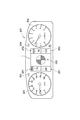
- FIG. 3 is a plan view illustrating a configuration example of an instrument panel 200 that includes the vehicle display device 1 according to the present embodiment and is disposed in front of a driver's seat of a vehicle such as an automobile.
- the vehicle display device 1 In the instrument panel 200 shown in FIG. 3, the vehicle display device 1 according to the present embodiment is disposed at the center, a circular speedometer (speedometer) 201 is disposed on the left side, and a circular tachometer is disposed on the right side. A (tachometer) 202 is arranged. Further, a turn L display unit 203, a turn R display unit 204, and the like are arranged.
- the vehicle display device 1 shown in FIG. 3 has a yaw moment display unit 300 indicating the state of the yaw moment of the vehicle at the center, and a display segment group 2A indicating the torque distribution state on the left and right of the yaw moment display unit 300. (2A1, 2A2), 2B (2B1, 2B2) are arranged.
- FIG 3 shows a state where the display segment 3a of the upper left display segment group 2A1 and the display segment 3b of the upper right display segment group 2A2 are lit.
- lighting modes (lighting patterns) of the display segments 3a to 3f and 4a to 4f in the display segment groups 2A (2A1, 2A2) and 2B (2B1, 2B2) will be described.
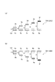
- FIG. 4A shows a transition state of the lighting positions of the display segments 3a to 3f in the display segment group 2A (2A1, 2A2).
- One display segment 3a-3f at a position corresponding to the quantity is selected and lit. In this case, as the amount of torque increases, the display segments 3a to 3f positioned in the upward direction are selected and turned on.
- the change amount V1 of the display segment 3a ⁇ 3b, the change amount V2 of the display segment 3a ⁇ 3c, the change amount V3 of the display segment 3a ⁇ 3d, and the change amount of the display segment 3a ⁇ 3e is V1 ⁇ V2 ⁇ V3 ⁇ V4 ⁇ V5.
- the display colors of the display segments 3b to 3f are changed so as to become darker as the change amounts V1 to V5 are larger. That is, as the amount of change in torque increases from 3b ⁇ 3c ⁇ 3d ⁇ 3e ⁇ 3f, for example, the display color is changed so as to gradually darken, such as light blue ⁇ blue ⁇ dark blue.
- the lighting color may be changed from a red system or the like to a cold system color such as a blue system or a green system in a gradation according to the amount of change in torque generated in the drive wheels.
- FIG. 4B shows a transition state of the lighting positions of the display segments 4a to 4f in the display segment group 2B (2B1, 2B2).
- One display segment 4a-4f at a position corresponding to the quantity is selected and lit.
- the display segments 4a to 4f positioned in the downward direction are selected and lighted as the minus amount of the torque amount increases.
- the change amount V1 of the display segment 4a ⁇ 4b, the change amount V2 of the display segment 4a ⁇ 4c, the change amount V3 of the display segment 4a ⁇ 4d, and the change amount of the display segment 4a ⁇ 4e is V1 ⁇ V2 ⁇ V3 ⁇ V4 ⁇ V5.
- the display colors of the display segments 4b to 4f are changed to become darker as the change amounts V1 to V5 are larger. That is, as the amount of change in torque increases from 4b ⁇ 4c ⁇ 4d ⁇ 4e ⁇ 4f, the display color is changed to gradually darken, for example, light red ⁇ red ⁇ dark red.
- the lighting color may be changed in gradation from a blue system or the like to an emphasized color (or warm color system) such as a red system or an orange system according to the amount of change in torque generated in the drive wheels.
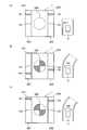
- FIG. 5 is an explanatory diagram showing a display example of torque and the like in the vehicle display device 1 according to the present embodiment.
- FIG. 5A is a display example of torque and the like when the vehicle C is traveling straight in the direction D1, as illustrated on the right side.
- the torque generated on the left wheel and the right wheel on the left and right of the moment display unit 300 indicating the state of the moment is the display segment 3b of the display segment group 2A1 on the drive side and the drive side. Is displayed by lighting the display segment 3b of the display segment group 2A2. That is, the torque difference between the left and right wheels when the vehicle C is traveling straight in the direction D1 is “0”, so the display mode is as described above.
- FIG. 5B is a display example of a torque amount or the like when a counterclockwise moment (in the direction of the arrow M1) is generated in the vehicle C as illustrated on the right side.
- the torques generated on the left and right wheels on the left and right of the moment display section 300 indicating the state of the moment are the display segment 4d of the display segment group 2B1 on the braking side and the braking side. Is displayed by lighting the display segment 4b of the display segment group 2B2. That is, for example, when the vehicle C is turning to the right while applying a brake, the braking force of the left wheel is greater than the braking force of the right wheel, so the display mode is as described above.
- FIG. 5C is a display example of the torque amount and the like when a clockwise (in the direction of arrow M2) moment is generated in the vehicle C, as shown on the right side.
- the torque generated on the left wheel and the right wheel on the left and right of the moment display section 300 indicating the state of the moment is the display segment 3a of the display segment group 2A1 on the driving side and the braking side. Is displayed by lighting the display segment 3b of the display segment group 2A2. That is, for example, when the vehicle C is turning right with the accelerator on, the torque of the left wheel is greater than the torque of the right wheel, so the display mode is as described above.
- the lighting positions of the display segments 3a to 3f and 4a to 4f in the display segment groups 2A (2A1, 2A2) and 2B (2B1, 2B2) transition in a straight line in the vertical direction.
- the present invention is not limited to this, and the lighting position may transition along an arc or a predetermined curve.
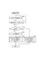
- This display control process is performed for each drive wheel (for example, left and right drive wheels in the case of two-wheel drive, and each drive wheel in the case of four-wheel drive).
- step S10 torque data is acquired from a predetermined sensor or the like provided in the vehicle, and the process proceeds to step S11.
- step S11 it is determined whether or not the vehicle is stopped based on the torque data. If “Yes”, the process returns to step S10, and if “No”, the process proceeds to step S12.
- step S12 it is determined whether or not the torque is on the drive side. If “Yes”, the process proceeds to step S13, and the position of the display segment group 2A (2A1, 2A2) on the drive side corresponds to the torque amount.
- the display segments 3a to 3f are selected and turned on, and the process ends.
- step S12 the process proceeds to step S14, and the process proceeds to step S15 assuming that the torque is on the braking side.
- step S15 in the display segment group 2B (2B1, 2B2) on the braking side, the display segments 4a to 4f at positions corresponding to the torque amount are selected and turned on, and the process is terminated.
- the torque amount is represented by a display area like a bar graph.
- the torque amount is represented by the number of display segments to be lit.
- the driver of the vehicle needs to recognize the area and the number of display segments in order to grasp the torque amount, and it takes some time to grasp the torque amount.
- the vehicle display device 1 as shown in FIG. 5, only the display segment corresponding to the peak position of the torque amount is lit, so that the driver of the vehicle There is an advantage that the amount can be grasped instantly. Further, when the color and density of the display segment are changed depending on the position of the display segment, it is further easy to grasp the torque amount.
- the vehicle display device of the present invention has been described based on the illustrated embodiment, but the present invention is not limited to this, and the configuration of each part is replaced with an arbitrary configuration having the same function. be able to.
Landscapes
- Engineering & Computer Science (AREA)
- Chemical & Material Sciences (AREA)
- Combustion & Propulsion (AREA)
- Transportation (AREA)
- Mechanical Engineering (AREA)
- Physics & Mathematics (AREA)
- General Physics & Mathematics (AREA)
- Instrument Panels (AREA)
- Indicating Measured Values (AREA)
- Arrangement And Driving Of Transmission Devices (AREA)
Abstract
車両用表示装置は車両の駆動輪に発生しているトルク量をグラフィック表示するトルク表示部(100)を備える。トルク表示部は、所定の基準部から上方向および下方向に配置され、表示制御部(5)の制御によって選択された位置の表示セグメントのみが点灯される表示セグメント群(2A、2B)を備える。駆動輪に発生しているトルク量がプラスの場合には、表示制御部(5)は所定の基準部(101)から上方向に配置された表示セグメント群のうち、トルク量に対応する表示セグメント(3a~4f)を選択して点灯させる。駆動輪に発生しているトルク量がマイナスの場合には、表示制御部(5)は所定の基準部から下方向に配置された表示セグメント群のうち、トルク量に対応する表示セグメント(4a~4f)を選択して点灯させる。
Description
本発明は、車両用表示装置に係り、特に、車輪トルク量を表示する車両用表示装置に関する。
従来から、自動車等の車両の運転席の前面に配置される計器盤において、スピードメータやタコメータ等の近傍に設置され、各車輪に現在配分されているトルクの大きさをグラフィック表示する表示装置が知られている。
実開昭63-42435号公報(特許文献1)に示すように、エンジンのトルクを前輪および後輪に配分可能な四輪駆動車両において、各車輪に現在配分されているトルクの大きさを、発光するLEDセグメントの数により表示する技術などが開示されている。
しかしながら、前記特許文献1に記載された技術では、トルク量を瞬時に判断できないという問題があった。
本発明は、上記課題に鑑みてなされたものであり、車輪のトルク状態及びその変化状態を視覚的に瞬時に把握することのできる車両用表示装置を提供することを目的とする。
上記目的を達成するため、本発明は第1のアスペクトより、車両の駆動輪に発生しているトルク量をグラフィック表示するトルク表示部であって、所定の基準部から上方向および下方向に配置された複数の表示セグメントを備えたものと、前記駆動輪に発生しているトルク量がプラスの場合には、前記所定の基準部から上方向に配置された複数の表示セグメントのうち、トルク量に対応する位置の表示セグメントを選択して点灯させ、前記駆動輪に発生しているトルク量がマイナスの場合には、前記所定の基準部から下方向に配置された複数の表示セグメントのうち、トルク量に対応する位置の表示セグメントを選択して点灯させるように制御する表示制御部と、を備えた車両用表示装置を提供する。
前記トルク表示部の前記表示セグメント群を構成する表示セグメントは、前記駆動輪に発生しているトルクの変化量が大きいほど表示色が濃くなるように構成してもよい。
本発明によれば、車輪のトルク状態及びその変化状態を視覚的に瞬時に把握することのできる車両用表示装置を提供することができる。
図1~図6を参照して、本発明の実施の形態について説明する。
(車両用表示装置の機能構成について)
図1は、本実施の形態に係る車両用表示装置1の機能構成を示す機能ブロック図である。
図1は、本実施の形態に係る車両用表示装置1の機能構成を示す機能ブロック図である。
本実施の形態に係る車両用表示装置1は、例えば四輪駆動車などのトルク配分を変更可能な車両の駆動輪に発生しているトルク量をグラフィック表示するトルク表示部100を備える。
トルク表示部100は、印刷あるいはLED等によって表示される基準部101から上方向および下方向に表示セグメント群2A、2Bがそれぞれ配置される。表示セグメント群2A、2Bは、それぞれ複数の表示セグメント3a~3f、4a~4fを備える。表示制御部5の制御によって選択された位置の表示セグメント3a~3f、4a~4fが点灯される。なお、表示セグメントの数は、図1に示すように6個ずつに限定されず、任意の数とすることができる。
表示制御部5は、駆動輪に発生しているトルク量がプラスの場合には、基準部101から上方向に配置された表示セグメント群2Aのうち、トルク量に対応する位置の表示セグメント3a~3fを選択して点灯させるように制御する。
また、駆動輪に発生しているトルク量がマイナスの場合には、基準部101から下方向に配置された前記表示セグメント群2Bのうち、トルク量に対応する位置の表示セグメント4a~4fを選択して点灯させるように制御する。
これにより、車輪のトルク状態を視覚的に瞬時に把握することが可能となる。
表示セグメント群2A、2Bは、例えばバックライトを備えたTFT方式の液晶表示器(TFT-LCD)で構成することができる。TFT-LCDを用いた表示セグメント群2A、2Bの構成例については後述する。また、具体的な表示態様についても後述する。
なお、表示セグメント群2A、2Bは、TFT方式の液晶表示器に限らず、LED表示器や面発光装置などで構成するようにしてもよい。
また、トルク表示部100の表示セグメント群2A、2Bを構成する表示セグメント3a~3f、4a~4fは、駆動輪に発生しているトルクの変化量に応じて表示色が変化するように構成してもよい。
また、トルク表示部100の表示セグメント群2A、2Bを構成する表示セグメント3a~3f、4a~4fは、駆動輪に発生しているトルクの変化量に応じて表示色の濃淡が変化するように構成してもよい。
例えば、駆動輪に発生しているトルク量の増減(プラスまたはマイナス)に関わりなく、表示セグメント3a~3fまたは4a~4fの点灯色について、トルクの変化量が大きいほど濃い色、トルクの変化量が小さいほど薄い色となるように変化させることができる。
これにより、視認性を一層向上させ、車輪のトルク状態を視覚的に瞬時に把握することが可能となる。
(車両用表示装置の回路構成について)
図2は、本実施の形態に係る車両用表示装置1の回路構成の例を示す回路図である。
図2は、本実施の形態に係る車両用表示装置1の回路構成の例を示す回路図である。
車両用表示装置1は、車両のメータパネルの一部を構成する表示パネル11、グラフィックコントローラ13、CPU15およびこのCPU15に接続される各種のI/Oインタフェース17、18を有する。
表示パネル11は、図1に示す表示セグメント群2A、2Bを構成し、グラフィック表示を行うカラーTFT液晶パネル(TFT-LCD)で構成される。また、グラフィックコントローラ13、Xドライバ21、Yドライバ23及びCPU15は、表示制御部5を構成する。
この表示パネル11は、水平同期信号に応じた電圧を印加するXドライバ21および垂直同期信号に応じた電圧を印加するYドライバ23によって駆動される。
また、表示パネル11には、LCD電源28からの印加電圧によって照度が調節されるバックライト11a(照明部)が設けられている。バックライト11aには、例えば、LED(Light Emitting Diode)、またはEL(Electro Luminescence)照明を用いることができる。このバックライト11aの照度を調節することで、表示パネル11に表示される画像(表示セグメント3a~3e、4a~4e)の輝度が変更される。
グラフィックコントローラ13は、表示セグメントのRGB画像データなど各種の画像データが格納されるフレームメモリ13aを有する。グラフィックコントローラ13は、このフレームメモリ13aに格納された画像データを表示パネル11に伝送する。また、グラフィックコントローラ13は、Xドライバ21に水平同期信号を出力し、Yドライバ23に垂直同期信号を出力する。
また、グラフィックコントローラ13は、CPU15からの指示に従って、画像データの値を変更することによりLCD透過率や色度を調節し、夜間点灯時、表示パネル11に表示される表示セグメント3a~3f、4a~4fの表示を調整する。LCD透過率や色度を用いることで各表示セグメントの表示色や濃淡の調整が容易となる。
CPU15には、EEPROM25が外付けされている。CPU15は、EEPROM25に格納された表示制御プログラムを実行し、表示パネル11に表示される表示セグメント3a~3e、4a~4e等の画像データを生成し、グラフィックコントローラ13に伝送する。
I/Oインタフェース17には、バッテリ(電源)51のプラス(+)に接続されたイグニッションスイッチ(IGN)52が接続され、イグニッションスイッチ52のON/OFFが入力される。
また、I/Oインタフェース18には、トルクデータ等が入力される。
また、CPU15には、バッテリ51に接続されたCPU電源27から電力が供給される。同様に、表示パネル11には、バッテリ51に接続されたLCD電源28から電力が供給される。LCD電源28は、TFT液晶11の各電極に電圧を印加するとともに、バックライト11aに電圧を印加する。
(計器盤の構成例)
図3は、本実施の形態に係る車両用表示装置1を備え、自動車等の車両の運転席の前面に配置される計器盤200の構成例を示す平面図である。
図3は、本実施の形態に係る車両用表示装置1を備え、自動車等の車両の運転席の前面に配置される計器盤200の構成例を示す平面図である。
図3に示す計器盤200においては、中央部に本実施の形態に係る車両用表示装置1が配置され、その左側に円形の速度計(スピードメータ)201が配置され、右側に円形の回転計(タコメータ)202が配置されている。また、ターンL表示部203、ターンR表示部204等が配置されている。
図3に示す車両用表示装置1は、中央部に車両のヨーモーメントの状態を示すヨーモーメント表示部300が配置され、このヨーモーメント表示部300の左右にトルクの配分状態を示す表示セグメント群2A(2A1、2A2)、2B(2B1、2B2)が配置されている。
図3に示す例では、左側の上方の表示セグメント群2A1の表示セグメント3aと、右側の上方の表示セグメント群2A2の表示セグメント3bとが点灯されている状態を示している。
ここで、図4を参照して、表示セグメント群2A(2A1、2A2)、2B(2B1、2B2)における表示セグメント3a~3f、4a~4fの点灯態様(点灯パターン)について説明する。
図4(a)は、表示セグメント群2A(2A1、2A2)における表示セグメント3a~3fの点灯位置の遷移状態を示す。
そして、図1に示す表示制御部5の制御により、駆動輪に発生しているトルク量がプラスの場合には、所定の基準部101から上方向に配置された表示セグメント群2Aのうち、トルク量に対応する位置の一つの表示セグメント3a~3fが選択されて点灯される。この場合、トルク量が大きいほど上方向に位置する表示セグメント3a~3fが選択されて点灯される。
そして、図4(a)に示す例において、表示セグメント3a→3bの変化量V1、表示セグメント3a→3cの変化量V2、表示セグメント3a→3dの変化量V3、表示セグメント3a→3eの変化量V4、表示セグメント3a→3fの変化量V5が、V1<V2<V3<V4<V5であるとする。この場合に、表示セグメント3b~3fの表示色は、変化量V1~V5が大きいほど濃くなるように変化される。即ち、3b→3c→3d→3e→3fとトルクの変化量が大きくなるにつれて、例えば、薄い青色→青色→濃い青色などというように表示色が徐々に濃くなるように変化される。
なお、駆動輪に発生しているトルクの変化量に応じて点灯色を赤系統などから青系統や緑系統等の寒色系の色にグラデーションで変化させるようにしてもよい。
図4(b)は、表示セグメント群2B(2B1、2B2)における表示セグメント4a~4fの点灯位置の遷移状態を示す。
そして、図1に示す表示制御部5の制御により、駆動輪に発生しているトルク量がマイナスの場合には、所定の基準部101から下方向に配置された表示セグメント群2Bのうち、トルク量に対応する位置の一つの表示セグメント4a~4fが選択されて点灯される。この場合、トルク量のマイナス量が大きいほど下方向に位置する表示セグメント4a~4fが選択されて点灯される。
そして、図4(b)に示す例において、表示セグメント4a→4bの変化量V1、表示セグメント4a→4cの変化量V2、表示セグメント4a→4dの変化量V3、表示セグメント4a→4eの変化量V4、表示セグメント4a→4fの変化量V5が、V1<V2<V3<V4<V5であるとする。この場合に、表示セグメント4b~4fの表示色は、変化量V1~V5が大きいほど濃くなるように変化される。即ち、4b→4c→4d→4e→4fとトルクの変化量が大きくなるにつれて、例えば、薄い赤色→赤色→濃い赤色などというように表示色が徐々に濃くなるように変化される。
なお、駆動輪に発生しているトルクの変化量に応じて点灯色を青系統などから赤系統や橙色系統等の強調色(あるいは暖色系の色)にグラデーションで変化させるようにしてもよい。
(トルク等の表示例)
図5は、本実施の形態に係る車両用表示装置1におけるトルク等の表示例を示す説明図である。
図5は、本実施の形態に係る車両用表示装置1におけるトルク等の表示例を示す説明図である。
図5(a)は、右側に図示するように、車両CがD1方向に直線走行している場合のトルク等の表示例である。
図5(a)に示す表示例では、モーメントの状態を示すモーメント表示部300の左右に、左車輪および右車輪に発生するトルクが、駆動側の表示セグメント群2A1の表示セグメント3bと、駆動側の表示セグメント群2A2の表示セグメント3bとの点灯によって表示されている。即ち、車両Cが駆動されるD1方向に直線走行している場合の左右車輪のトルク差は「0」となるので、上述のような表示態様となる。
図5(b)は、右側に図示するように、車両Cに反時計回り(矢印M1方向)のモーメントが生じた場合のトルク量等の表示例である。
図5(b)に示す表示例では、モーメントの状態を示すモーメント表示部300の左右に、左車輪および右車輪に発生するトルクが、制動側の表示セグメント群2B1の表示セグメント4dと、制動側の表示セグメント群2B2の表示セグメント4bとの点灯によって表示されている。即ち、例えば車両Cがブレーキをかけながら右方向に旋回している場合には、左車輪の制動力が右車輪の制動力より大きい状態となるので、上述のような表示態様となる。
図5(c)は、右側に図示するように、車両Cに時計回り(矢印M2方向)のモーメントが生じた場合のトルク量等の表示例である。
図5(c)に示す表示例では、モーメントの状態を示すモーメント表示部300の左右に、左車輪および右車輪に発生するトルクが、駆動側の表示セグメント群2A1の表示セグメント3aと、制動側の表示セグメント群2A2の表示セグメント3bとの点灯によって表示されている。即ち、例えば車両Cがアクセルオンの状態で右方向に旋回している場合には、左車輪のトルクが右車輪のトルクより大きい状態となるので、上述のような表示態様となる。
なお、図5における表示態様では、表示セグメント群2A(2A1、2A2)、2B(2B1、2B2)における表示セグメント3a~3fおよび4a~4fは、上下方向の直線状に点灯位置が遷移する。これに限らず、円弧状や所定の曲線に沿って点灯位置が遷移するようにしてもよい。
(表示処理制御)
図6に示すフローチャートを参照して、本実施の形態に係る車両用表示装置1で実行される表示制御処理の処理手順の例について説明する。
図6に示すフローチャートを参照して、本実施の形態に係る車両用表示装置1で実行される表示制御処理の処理手順の例について説明する。
なお、この表示制御処理は、駆動輪ごと(例えば、二輪駆動の場合には左右駆動輪、四輪駆動の場合には各駆動輪ごと)に行われる。
まず、ステップS10では、車両が備える所定のセンサ等からトルクデータを取得してステップS11に移行する。
ステップS11では、トルクデータに基いて車両が停止しているか否かが判定され、「Yes」の場合にはステップS10に戻り、「No」の場合にはステップS12に移行する。
ステップS12では、トルクは駆動側か否かが判定され、「Yes」の場合にはステップS13に移行して、駆動側の表示セグメント群2A(2A1、2A2)において、トルク量に対応する位置の表示セグメント3a~3fを選択して点灯し、処理を終了する。
一方、ステップS12で「No」の場合には、ステップS14に移行してトルクは制動側であるとしてステップS15に移行する。
ステップS15では、制動側の表示セグメント群2B(2B1、2B2)において、トルク量に対応する位置の表示セグメント4a~4fを選択して点灯し、処理を終了する。
以上の処理手順を各駆動輪ごとに行うことにより、図5に示すようなトルクの表示態様を実現することができる。
これにより、車輪のトルク状態を視覚的に瞬時に把握することが可能となる。
(比較例)
図7を参照して、比較例に係る車両用表示装置の表示態様の例について簡単に説明する。
図7を参照して、比較例に係る車両用表示装置の表示態様の例について簡単に説明する。
図7(a)に示す比較例では、トルク量を棒グラフのように表示面積で表している。また、図7(b)に示す比較例では、トルク量を点灯される表示セグメントの数で表している。
何れの比較例においても、車両の運転者は、トルク量を把握するために面積や表示セグメントの数を認識する必要があり、トルク量の把握に若干時間を要する。
これに対して、本実施の形態に係る車両用表示装置1では、図5に示すように、トルク量のピーク位置に相当する表示セグメントのみを点灯させているので、車両の運転者は、トルク量を瞬時に把握することができるというメリットがある。また、表示セグメントの色や濃度を表示セグメントの位置により変化させた場合には、さらに、トルク量の把握が容易になる。
以上、本発明の車両用表示装置を図示の実施形態に基づいて説明したが、本発明はこれに限定されるものではなく、各部の構成は、同様の機能を有する任意の構成のものに置き換えることができる。
Claims (3)
- 車両の駆動輪に発生しているトルク量をグラフィック表示するトルク表示部であって、所定の基準部から上方向および下方向に配置された複数の表示セグメントを備えたものと、
前記駆動輪に発生しているトルク量がプラスの場合には、前記所定の基準部から上方向に配置された複数の表示セグメントのうち、トルク量に対応する位置の表示セグメントを選択して点灯させ、前記駆動輪に発生しているトルク量がマイナスの場合には、前記所定の基準部から下方向に配置された複数の表示セグメントのうち、トルク量に対応する位置の表示セグメントを選択して点灯させるように制御する表示制御部と、
を備えた車両用表示装置。 - 前記トルク表示部の表示セグメントは、前記駆動輪に発生しているトルクの変化量が大きいほど表示色が濃くなるように構成されている請求項1に記載の車両用表示装置。
- 前記表示制御部は、トルク量がプラスの場合には、トルク量が大きいほど上方向に位置する表示セグメントを選択して点灯させ、トルク量がマイナスの場合には、トルク量のマイナス量が大きいほど下方向に位置する表示セグメントを選択して点灯させる請求項1又は2に記載の車両用表示装置。
Applications Claiming Priority (2)
| Application Number | Priority Date | Filing Date | Title |
|---|---|---|---|
| JP2014-002212 | 2014-01-09 | ||
| JP2014002212A JP2015129728A (ja) | 2014-01-09 | 2014-01-09 | 車両用表示装置 |
Publications (1)
| Publication Number | Publication Date |
|---|---|
| WO2015105018A1 true WO2015105018A1 (ja) | 2015-07-16 |
Family
ID=53523852
Family Applications (1)
| Application Number | Title | Priority Date | Filing Date |
|---|---|---|---|
| PCT/JP2014/084465 Ceased WO2015105018A1 (ja) | 2014-01-09 | 2014-12-26 | 車両用表示装置 |
Country Status (2)
| Country | Link |
|---|---|
| JP (1) | JP2015129728A (ja) |
| WO (1) | WO2015105018A1 (ja) |
Citations (7)
| Publication number | Priority date | Publication date | Assignee | Title |
|---|---|---|---|---|
| JPS6262215U (ja) * | 1985-10-08 | 1987-04-17 | ||
| JPS63189886A (ja) * | 1987-02-02 | 1988-08-05 | 株式会社日立製作所 | カラ−液晶表示装置 |
| JP2000136946A (ja) * | 1998-11-02 | 2000-05-16 | Harness Syst Tech Res Ltd | 車載用表示装置 |
| JP2005022627A (ja) * | 2003-06-10 | 2005-01-27 | Nissan Motor Co Ltd | 車両用運転操作補助装置および車両用運転操作補助装置を備えた車両 |
| JP2011046362A (ja) * | 2009-08-28 | 2011-03-10 | Honda Motor Co Ltd | 車両用トルク表示装置 |
| WO2011108091A1 (ja) * | 2010-03-03 | 2011-09-09 | 株式会社 東芝 | 車載用表示装置及び表示方法 |
| JP2012026759A (ja) * | 2010-07-20 | 2012-02-09 | Nippon Seiki Co Ltd | 車両用計器の照明装置 |
-
2014
- 2014-01-09 JP JP2014002212A patent/JP2015129728A/ja not_active Abandoned
- 2014-12-26 WO PCT/JP2014/084465 patent/WO2015105018A1/ja not_active Ceased
Patent Citations (7)
| Publication number | Priority date | Publication date | Assignee | Title |
|---|---|---|---|---|
| JPS6262215U (ja) * | 1985-10-08 | 1987-04-17 | ||
| JPS63189886A (ja) * | 1987-02-02 | 1988-08-05 | 株式会社日立製作所 | カラ−液晶表示装置 |
| JP2000136946A (ja) * | 1998-11-02 | 2000-05-16 | Harness Syst Tech Res Ltd | 車載用表示装置 |
| JP2005022627A (ja) * | 2003-06-10 | 2005-01-27 | Nissan Motor Co Ltd | 車両用運転操作補助装置および車両用運転操作補助装置を備えた車両 |
| JP2011046362A (ja) * | 2009-08-28 | 2011-03-10 | Honda Motor Co Ltd | 車両用トルク表示装置 |
| WO2011108091A1 (ja) * | 2010-03-03 | 2011-09-09 | 株式会社 東芝 | 車載用表示装置及び表示方法 |
| JP2012026759A (ja) * | 2010-07-20 | 2012-02-09 | Nippon Seiki Co Ltd | 車両用計器の照明装置 |
Also Published As
| Publication number | Publication date |
|---|---|
| JP2015129728A (ja) | 2015-07-16 |
Similar Documents
| Publication | Publication Date | Title |
|---|---|---|
| EP1870274B1 (en) | Display device, instrument panel, automotive vehicle and method for controlling instrument panel | |
| CN101051129B (zh) | 液晶显示装置 | |
| US11170722B2 (en) | Display device with a backlight | |
| CN105101529B (zh) | 用于车辆显示器照明的led驱动器 | |
| RU2010103674A (ru) | Способ и система для управления фоновой подсветкой в дисплее | |
| US20080185976A1 (en) | Display backlight system and method | |
| TW200632438A (en) | Monochromatic liquid crystal display for colors | |
| CN109986964B (zh) | 仪表显示装置 | |
| JP4229923B2 (ja) | 表示装置、インストルメントパネル、自動車両およびインストルメントパネルの制御方法 | |
| JP2013226984A (ja) | 車両用計器板装置 | |
| JP5909329B2 (ja) | 車両用表示装置 | |
| EP2483099B1 (en) | Display unit | |
| JP2019028102A (ja) | 画像表示装置および画像表示方法 | |
| CN109386811B (zh) | 车辆用灯具 | |
| WO2015105018A1 (ja) | 車両用表示装置 | |
| WO2013118549A1 (ja) | 車両用表示装置 | |
| WO2015105020A1 (ja) | 車両用表示装置 | |
| JP2010197931A (ja) | 液晶表示装置 | |
| JP2018159743A (ja) | 画像表示装置および画像表示装置の制御方法 | |
| CN109442342A (zh) | 车辆用灯具 | |
| KR101851320B1 (ko) | 점멸 신호등 및 그 제어방법 | |
| JP4966093B2 (ja) | 作業車輌 | |
| JP2017140983A (ja) | 車両用表示装置 | |
| EP2779149B1 (en) | Method and intensity adjustment system for intensity adjustment of a vehicle display | |
| KR20060035404A (ko) | 가변유리를 장착한 차량의 투명도 조절 장치 |
Legal Events
| Date | Code | Title | Description |
|---|---|---|---|
| 121 | Ep: the epo has been informed by wipo that ep was designated in this application |
Ref document number: 14877850 Country of ref document: EP Kind code of ref document: A1 |
|
| NENP | Non-entry into the national phase |
Ref country code: DE |
|
| 122 | Ep: pct application non-entry in european phase |
Ref document number: 14877850 Country of ref document: EP Kind code of ref document: A1 |