WO2015105111A1 - Chenille élastique - Google Patents
Chenille élastique Download PDFInfo
- Publication number
- WO2015105111A1 WO2015105111A1 PCT/JP2015/050207 JP2015050207W WO2015105111A1 WO 2015105111 A1 WO2015105111 A1 WO 2015105111A1 JP 2015050207 W JP2015050207 W JP 2015050207W WO 2015105111 A1 WO2015105111 A1 WO 2015105111A1
- Authority
- WO
- WIPO (PCT)
- Prior art keywords
- elastic crawler
- crawler
- reinforcing member
- wing
- elastic
- Prior art date
- Legal status (The legal status is an assumption and is not a legal conclusion. Google has not performed a legal analysis and makes no representation as to the accuracy of the status listed.)
- Ceased
Links
Images

Classifications
-
- B—PERFORMING OPERATIONS; TRANSPORTING
- B62—LAND VEHICLES FOR TRAVELLING OTHERWISE THAN ON RAILS
- B62D—MOTOR VEHICLES; TRAILERS
- B62D55/00—Endless track vehicles
- B62D55/08—Endless track units; Parts thereof
- B62D55/18—Tracks
- B62D55/24—Tracks of continuously flexible type, e.g. rubber belts
- B62D55/244—Moulded in one piece, with either smooth surfaces or surfaces having projections, e.g. incorporating reinforcing elements
Definitions
- the present invention relates to an elastic crawler that is attached to an agricultural machine such as a combine or tractor, or a crawler type traveling device of a construction machine such as a backhoe.
- An elastic crawler mounted on a crawler type traveling device such as an agricultural machine is provided with both sides in the width direction thereof.
- a crawler-type traveling device for a construction machine that often travels on rough and uneven ground tends to get scattered stones, building waste, etc. between the rollers and the elastic crawler.
- the total weight of the crawler type traveling device is added to the wheel running zone through the wheels, and stones, building waste, etc. sandwiched between the wheel and the elastic crawler damage the surface of the wheel running zone.
- scratches (wormworms, chip cuts) of the wheel running belt grow and reach the cored bar.
- rust is generated in the cored bar due to moisture that has entered after flaws, and eventually the cored bar and the crawler main body (rubber) are damaged and the cored bar is peeled off.
- Patent Document 1 a technique has been proposed in which the surface of the wheel running zone is configured with a rubber layer having high insect resistance and high hardness.
- Patent Document 1 Since the technique proposed in Patent Document 1 forms the wheel running zone with a rubber having high hardness, it can be expected that the occurrence of scratches on the wheel running zone is suppressed to a certain extent.
- the elastic crawler described in Patent Document 1 since the wheel runs on the wheel running zone where the rubber having high hardness and poor elasticity is exposed, vibration of the crawler type traveling device during running increases. There are concerns.
- the ground on which the crawler type traveling device travels has many stones with sharp corners and construction waste materials from which metal is exposed. It is likely to reach gold.
- the present invention has been made in view of the above-described problems, and there is no or little increase in vibration of the crawler type traveling device during traveling. It is an object of the present invention to provide an elastic crawler capable of preventing gold peeling.
- the elastic crawler according to the present invention is provided with a wheel running zone in which a mandrel is embedded in a crawler main body and a wheel of a crawler type traveling device to be attached runs on both sides in the width direction on the inner peripheral side.
- An elastic crawler has a wing
- the elastic crawler has a reinforcing member embedded between the wheel travel zone and the wings that overlap the wheel travel zone when viewed from the inner periphery.
- the reinforcing member is in the shape of a band between the wheel running zone and the wings that overlap the wheel running zone, and has higher tensile strength than rubber that is flexible and forms the crawler body.
- the “strip shape” refers to a form having a width larger than the thickness regardless of the magnitude relationship between the length and the width.
- One form of the reinforcing member has flexibility, and goes around the crawler body in the circumferential direction.
- Another form of the reinforcing member is cylindrical, and each wing is accommodated inside the wing to cover the wing.
- the size of the reinforcing member in the width direction of the elastic crawler is a size that can project the entire width of the wheel running zone when the elastic crawler is viewed from the inner peripheral side.
- the “width-wise dimension of the elastic crawler” is the width of the belt-shaped reinforcing member that goes around the crawler body in the circumferential direction, and the length of the cylinder of the cylindrical reinforcing member that covers the wing portion for each core metal. is there.
- the reinforcing member between the wheel travel zone and the wing portion overlapping the wheel travel zone is such that the distance between the surface facing the wing portion and the wing portion is It is less than half of the distance from the surface of the wheel running zone.
- the reinforcing member is formed of a synthetic fiber fabric, a metal wire knitted fabric, a canvas, or a rubber having a hardness higher than that of the rubber constituting the crawler body.
- a reinforcing member formed of a synthetic fiber fabric or a woven metal wire is embedded in the crawler body so that the synthetic fiber yarn or metal wire is inclined with respect to the circumferential direction of the crawler body. .
- a crawler there is no or little increase in vibration of the crawler type traveling device during traveling, and elasticity that can prevent the core metal from peeling by suppressing the ingress of scratches even if the rolling wheel traveling zone is damaged.
- a crawler can be provided.
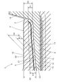
- FIG. 1 is a cross-sectional view of the elastic crawler in the width direction.
- FIG. 2 is an enlarged view around the wing portion of the cored bar in FIG.
- FIG. 3 is a view showing a relationship between the cored bar and the reinforcing member in the elastic crawler.
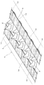
- FIG. 4 is a view showing the relationship between another reinforcing member in the elastic crawler and the cored bar.
- FIG. 1 is a cross-sectional view of the elastic crawler 1 in the width direction
- FIG. 2 is an enlarged view around the wing portion 14 of the core metal 2 in FIG. 1
- FIG. 3 shows the relationship between the core metal 2 in the elastic crawler 1 and the reinforcing member 3.
- the elastic crawler 1 includes a crawler body 4, a lug 5, a cored bar 2, a pair of tensile bodies 6 and 6, a pair of reinforcing members 3 and 3, and the like.
- the crawler body 4 is formed by forming a thick belt-like rubber into a ring with a direction perpendicular to the width direction and the thickness direction as a circumferential direction.
- width direction and circumferential direction refer to the width direction and the circumferential direction of the crawler body 4, respectively.
- the crawler body 4 has a plurality of drive holes 11 arranged at substantially equal intervals in the circumferential direction.
- the drive hole 11 is arranged at the approximate center in the width direction.
- the drive hole 11 is inserted into the claw of the drive sprocket of the crawler type travel device, and the elastic crawler 1 is circulated by the rotating drive sprocket to run the crawler type travel device.
- the driving hole 11 is closed on the outer peripheral side and is opened only on the inner peripheral side.
- the drive hole 11 may be penetrated in the thickness direction of the crawler body 4.
- the crawler main body 4 is provided with a pair of wheel running zones 12 and 12 for running the wheels of the crawler type traveling device at intervals on both sides in the width direction of the inner peripheral surface.
- the wheel running zone 12 makes one round of the crawler body 4 continuously or intermittently.
- the “rolling wheel traveling zone 12” refers to a portion having a certain thickness including rubber on the surface and in the vicinity of the surface.
- the lugs 5 extend in the width direction from the outer peripheral side of the crawler main body 4 that is a ring, protrude outward, and a plurality of lugs are arranged at intervals in the circumferential direction.
- the lug 5 is located between the adjacent drive holes 11 and 11 in the circumferential direction.
- the lug 5 in FIG. 1 continues without interruption between both ends in the width direction, but the shape of the lug can be arbitrarily selected depending on the use of the elastic crawler.
- the core metal 2 has a long and narrow plate shape as a whole.
- the cored bar 2 is embedded between adjacent drive holes 11 of the crawler body 4 so that the longitudinal direction thereof is the width direction of the crawler body 4.
- a pair of protrusions 13 and 13 are provided that protrude inward on the inner peripheral side with an interval in the width direction.
- the pair of protrusions 13, 13 are located between the pair of wheel travel zones 12, 12.
- a plate-like portion from the protruding portion 13 to the outer end in the width direction in the core metal 2 is referred to as a wing portion 14.
- the tensile body 6 is formed by arranging steel cords 15,.
- the tensile body 6 is embedded in the crawler body 4 in a state where the outer peripheral side of the wing portion 14 of the core metal 2 is made to make one round in the circumferential direction on both sides in the width direction.
- the reinforcing member 3 is formed by stacking one or a plurality of band-shaped materials having higher tensile strength than the rubber forming the crawler body 4.
- the band-shaped material is a woven fabric, a knitted fabric, a sheet or the like having flexibility.
- the reinforcing member 3 is embedded in the crawler body 4 with the inner peripheral side of the wing portion 14 of the cored bar 2 making one round in the circumferential direction on both sides in the width direction.
- the belt-like reinforcing member 3 embedded in the crawler body 4 may be an endless (endless) ring, or both ends thereof may not be connected.
- the reinforcing member 3 has a width capable of projecting at least the entire wheel travel zone 12 when the elastic crawler 1 is viewed from the inner peripheral side. Therefore, the reinforcing member 3 has a width W1 that is the same as or larger than the width W2 of the wheel travel zone 12 (W1 ⁇ W2). Further, in the portion of the reinforcing member 3 that overlaps with the wheel running zone 12, referring to FIG. 2, the distance D 1 between the inner peripheral surface 21 of the wing portion 14 of the core metal 2 and the reinforcing member 3 is the core metal 2.
- the distance D2 between the inner peripheral surface 21 of the wing portion 14 and the surface 22 of the wheel traveling zone 12 is 1 ⁇ 2 or less (D1 ⁇ D2 ⁇ 2), and 1 / or less (D1 ⁇ D2 ⁇ 3). More preferably it is.
- the distance D1 refers to the distance between the inner peripheral surface 21 of the wing part 14 and the surface of the reinforcing member 3 opposed to the inner peripheral surface 21.
- the reinforcing member 3 is made of a synthetic fiber (yarn) woven material such as nylon or polyester, a metal wire knitted fabric, a canvas (canvas), or an elastomer such as rubber having higher hardness than the rubber constituting the crawler body 4. Is done.
- both the warp and the weft are inclined with respect to the longitudinal direction (band-like).
- the fibers are inclined (bias cord) with respect to the circumferential direction in the elastic crawler 1.
- belt-like canvases 23 and 23 are embedded between the wing portion 14 of the core metal 2 and the tensile body 6 on both sides in the width direction. The canvas 23 prevents the tensile body 6 from contacting the wing part 14 of the core metal 2.
- the elastic crawler 1 has a reinforcing member 3 that is different from the rubber forming the crawler main body 4 between the wheel travel zone 12 and the wing portion 14 of the core metal 2. For this reason, even if a scratch generated on the surface 22 of the wheel running belt 12 grows and enters the crawler main body 4, the foreign reinforcing member 3 prevents further penetration of the scratch into the inside.
- the reinforcing member 3 blocks the entry of pebbles and the like that have entered the wound and prevents the pebbles and the like from reaching the cored bar 2.
- FIG. 4 is a view showing a relationship between another reinforcing member 3 ⁇ / b> B in the elastic crawler and the cored bar 2.
- the reinforcing member 3B is formed by forming a woven fabric, a knitted fabric, a sheet, or the like having a higher tensile strength than the rubber forming the crawler body 4 into a cylindrical shape. It can be said that the cylindrical reinforcing member 3B is obtained by connecting both ends of a band-shaped material.
- the reinforcing member 3B preferably has flexibility.
- the reinforcing member 3 ⁇ / b> B covers the two wing portions 14 for each core metal 2.
- the cylindrical reinforcing member 3B that covers the wing portion 14 of the core metal 2 has a length (cylinder) that can project at least the full width of the wheel running zone when the elastic crawler is viewed from the inner peripheral side. . Therefore, the length of the cylinder is the same as or larger than the width of the wheel travel zone.
- the reinforcing member 3B is the same material used for the reinforcing member 3 in the elastic crawler 1, that is, a woven fabric of synthetic fibers (yarns) such as nylon and polyester, a woven metal wire, a canvas (canvas), or a crawler It is made of an elastomer such as rubber having a higher hardness than the rubber constituting the main body 4.
- a woven fabric or a knitted fabric is used for the reinforcing member 3B, it is preferable that the reinforcing member 3B is a woven or knitted fabric so that the fibers are oblique to the length direction of the cylinder.
- the elastic crawlers in which the reinforcing members 3B,..., 3B cover the wings 14, 14 of the core bars 2,..., 2 are generated in the wheel running zone as in the elastic crawler 1 in which the reinforcing members 3 and 3 are embedded. It prevents the scratches from reaching the surface of the core metal 2 and prevents the core metal from rusting.
- the reinforcing member 3 ⁇ / b> B prevents the rubber from peeling from the cored bar 2 without increasing the vibration of the crawler type traveling device during traveling, and improves the durability of the elastic crawler 1.
- the configuration of the elastic crawler 1 and the elastic crawler 1 or the overall structure, shape, dimensions, number, material, and the like can be appropriately changed in accordance with the spirit of the present invention.
- the present invention can be used for an elastic crawler mounted on a crawler type traveling device of an agricultural machine such as a combine or tractor, or a construction machine such as a backhoe.
Landscapes
- Engineering & Computer Science (AREA)
- Chemical & Material Sciences (AREA)
- Combustion & Propulsion (AREA)
- Transportation (AREA)
- Mechanical Engineering (AREA)
- Tires In General (AREA)
- Woven Fabrics (AREA)
Abstract
L'invention porte sur une chenille élastique qui est configurée de telle sorte qu'une augmentation de la vibration d'un dispositif de déplacement du type à chenilles, pendant le déplacement, ne se produit pas ou est réduite à un minimum, et de sorte qu'il est possible d'empêcher une fissure de se propager à l'intérieur, même si une courroie de déplacement de roue est endommagée, empêchant ainsi la séparation d'un noyau métallique. Une chenille élastique (1) est configurée de telle manière que des noyaux métalliques (2) sont incorporés dans un corps de chenille (4), et que des courroies de déplacement de roues (12), sur lesquelles se déplacent les roues d'un dispositif de déplacement du type à chenilles ayant la chenille élastique (1) montée sur celui-ci, sont respectivement disposées des deux côtés du côté périphérique interne de la chenille élastique (1) dans la direction de la largeur de celle-ci. Dans la chenille élastique, les noyaux métalliques ont des sections aile (14) s'étendant vers les deux extrémités de la chenille élastique (1), les extrémités étant situées des deux côtés de la chenille élastique (1) dans la direction de la largeur de celle-ci. La chenille élastique possède des éléments de renfort (3) incorporés à l'intérieur de celle-ci, les éléments de renfort (3) étant disposés entre les courroies de déplacement des roues et les sections aile qui chevauchent les courroies de déplacement des roues quand la chenille élastique est vue du côté périphérique interne. Les éléments de renfort sont formés sous une forme du type courroie entre les courroies de déplacement des roues et les sections aile qui chevauchent les courroies de déplacement des roues. Les éléments de renfort sont souples et ont une résistance à la traction supérieure à celle du caoutchouc qui forme le corps de chenille.
Priority Applications (1)
| Application Number | Priority Date | Filing Date | Title |
|---|---|---|---|
| CN201580003975.2A CN105899426B (zh) | 2014-01-10 | 2015-01-07 | 弹性履带 |
Applications Claiming Priority (2)
| Application Number | Priority Date | Filing Date | Title |
|---|---|---|---|
| JP2014003343A JP2015131536A (ja) | 2014-01-10 | 2014-01-10 | 弾性クローラ |
| JP2014-003343 | 2014-01-10 |
Publications (1)
| Publication Number | Publication Date |
|---|---|
| WO2015105111A1 true WO2015105111A1 (fr) | 2015-07-16 |
Family
ID=53523936
Family Applications (1)
| Application Number | Title | Priority Date | Filing Date |
|---|---|---|---|
| PCT/JP2015/050207 Ceased WO2015105111A1 (fr) | 2014-01-10 | 2015-01-07 | Chenille élastique |
Country Status (3)
| Country | Link |
|---|---|
| JP (1) | JP2015131536A (fr) |
| CN (1) | CN105899426B (fr) |
| WO (1) | WO2015105111A1 (fr) |
Cited By (1)
| Publication number | Priority date | Publication date | Assignee | Title |
|---|---|---|---|---|
| CN110937039A (zh) * | 2018-09-21 | 2020-03-31 | 住友橡胶工业株式会社 | 弹性履带 |
Families Citing this family (3)
| Publication number | Priority date | Publication date | Assignee | Title |
|---|---|---|---|---|
| JP7060871B2 (ja) * | 2018-04-05 | 2022-04-27 | 福山ゴム工業株式会社 | クローラ |
| JP7346841B2 (ja) * | 2019-02-20 | 2023-09-20 | 住友ゴム工業株式会社 | 弾性クローラ |
| CN116176718B (zh) * | 2023-05-04 | 2024-03-26 | 中策橡胶集团股份有限公司 | 一种高性能大尺寸橡胶履带 |
Citations (9)
| Publication number | Priority date | Publication date | Assignee | Title |
|---|---|---|---|---|
| JPH0347895U (fr) * | 1989-09-19 | 1991-05-07 | ||
| JPH0411190U (fr) * | 1990-05-18 | 1992-01-30 | ||
| JPH0426892U (fr) * | 1990-06-29 | 1992-03-03 | ||
| JPH06144310A (ja) * | 1992-11-04 | 1994-05-24 | Bridgestone Corp | ゴムクローラ |
| JPH08133144A (ja) * | 1994-11-07 | 1996-05-28 | Bridgestone Corp | ゴムクロ−ラ |
| JPH08301156A (ja) * | 1995-05-12 | 1996-11-19 | Fukuyama Gomme Kogyo Kk | 連結リンク式ゴムクローラ及び連結リンク式ゴムクロ ーラ用芯金 |
| JP2005343273A (ja) * | 2004-06-02 | 2005-12-15 | Sumitomo Rubber Ind Ltd | 弾性クローラ |
| JP2006142928A (ja) * | 2004-11-18 | 2006-06-08 | Bridgestone Corp | ゴムクロ−ラのエンドレス構造 |
| JP2010132082A (ja) * | 2008-12-03 | 2010-06-17 | Sumitomo Rubber Ind Ltd | ゴムクローラ |
Family Cites Families (4)
| Publication number | Priority date | Publication date | Assignee | Title |
|---|---|---|---|---|
| JP4578550B2 (ja) * | 2008-11-10 | 2010-11-10 | 住友ゴム工業株式会社 | 弾性履帯 |
| CN103118930B (zh) * | 2010-09-21 | 2015-09-30 | 株式会社普利司通 | 弹性履带 |
| US9545964B2 (en) * | 2011-04-05 | 2017-01-17 | Bridgestone Corporation | Crawler traveling device and elastic crawler |
| JP5554744B2 (ja) * | 2011-04-12 | 2014-07-23 | 住友ゴム工業株式会社 | ゴムクローラ |
-
2014
- 2014-01-10 JP JP2014003343A patent/JP2015131536A/ja active Pending
-
2015
- 2015-01-07 CN CN201580003975.2A patent/CN105899426B/zh active Active
- 2015-01-07 WO PCT/JP2015/050207 patent/WO2015105111A1/fr not_active Ceased
Patent Citations (9)
| Publication number | Priority date | Publication date | Assignee | Title |
|---|---|---|---|---|
| JPH0347895U (fr) * | 1989-09-19 | 1991-05-07 | ||
| JPH0411190U (fr) * | 1990-05-18 | 1992-01-30 | ||
| JPH0426892U (fr) * | 1990-06-29 | 1992-03-03 | ||
| JPH06144310A (ja) * | 1992-11-04 | 1994-05-24 | Bridgestone Corp | ゴムクローラ |
| JPH08133144A (ja) * | 1994-11-07 | 1996-05-28 | Bridgestone Corp | ゴムクロ−ラ |
| JPH08301156A (ja) * | 1995-05-12 | 1996-11-19 | Fukuyama Gomme Kogyo Kk | 連結リンク式ゴムクローラ及び連結リンク式ゴムクロ ーラ用芯金 |
| JP2005343273A (ja) * | 2004-06-02 | 2005-12-15 | Sumitomo Rubber Ind Ltd | 弾性クローラ |
| JP2006142928A (ja) * | 2004-11-18 | 2006-06-08 | Bridgestone Corp | ゴムクロ−ラのエンドレス構造 |
| JP2010132082A (ja) * | 2008-12-03 | 2010-06-17 | Sumitomo Rubber Ind Ltd | ゴムクローラ |
Cited By (1)
| Publication number | Priority date | Publication date | Assignee | Title |
|---|---|---|---|---|
| CN110937039A (zh) * | 2018-09-21 | 2020-03-31 | 住友橡胶工业株式会社 | 弹性履带 |
Also Published As
| Publication number | Publication date |
|---|---|
| CN105899426B (zh) | 2018-05-18 |
| CN105899426A (zh) | 2016-08-24 |
| JP2015131536A (ja) | 2015-07-23 |
Similar Documents
| Publication | Publication Date | Title |
|---|---|---|
| JP4087619B2 (ja) | 弾性クローラ | |
| EP3133000B1 (fr) | Chenille | |
| CN102131693A (zh) | 橡胶履带及履带式行驶体 | |
| WO2015105111A1 (fr) | Chenille élastique | |
| JP2003089366A (ja) | 弾性クローラ | |
| JP5213377B2 (ja) | ゴムクローラ | |
| US3515443A (en) | Traction belt | |
| JP2013166475A (ja) | 弾性クローラ | |
| JP5554744B2 (ja) | ゴムクローラ | |
| JP4282553B2 (ja) | 弾性クローラ | |
| JP4675488B2 (ja) | 弾性クローラ | |
| AU2017256518B2 (en) | Vehicle track | |
| JP5213376B2 (ja) | 弾性クローラおよび弾性クローラの製造方法 | |
| US7063395B2 (en) | Laterally reinforced endless belt track | |
| JP2009090860A (ja) | ゴムクローラ | |
| JP5770560B2 (ja) | 弾性クローラ及びクローラ走行装置 | |
| US9902445B2 (en) | Crawler | |
| JP4423110B2 (ja) | 弾性クローラ | |
| JP2001114144A (ja) | 弾性クローラ及びその製造方法 | |
| JP3199025U (ja) | クローラ | |
| JP7204469B2 (ja) | クローラ | |
| JP2024116770A (ja) | 弾性クローラ | |
| JP2002321667A (ja) | 弾性クローラ | |
| JPH08192780A (ja) | 弾性クローラ | |
| WO2018190996A1 (fr) | Carcasse de chenille en caoutchouc renforcée de tissu pour une durabilité améliorée de charge/vitesse |
Legal Events
| Date | Code | Title | Description |
|---|---|---|---|
| 121 | Ep: the epo has been informed by wipo that ep was designated in this application |
Ref document number: 15734862 Country of ref document: EP Kind code of ref document: A1 |
|
| NENP | Non-entry into the national phase |
Ref country code: DE |
|
| 122 | Ep: pct application non-entry in european phase |
Ref document number: 15734862 Country of ref document: EP Kind code of ref document: A1 |