WO2015105178A1 - 自走式機器 - Google Patents
自走式機器 Download PDFInfo
- Publication number
- WO2015105178A1 WO2015105178A1 PCT/JP2015/050490 JP2015050490W WO2015105178A1 WO 2015105178 A1 WO2015105178 A1 WO 2015105178A1 JP 2015050490 W JP2015050490 W JP 2015050490W WO 2015105178 A1 WO2015105178 A1 WO 2015105178A1
- Authority
- WO
- WIPO (PCT)
- Prior art keywords
- unit
- traveling body
- signal
- main body
- identification information
- Prior art date
- Legal status (The legal status is an assumption and is not a legal conclusion. Google has not performed a legal analysis and makes no representation as to the accuracy of the status listed.)
- Ceased
Links
Images


Classifications
-
- G—PHYSICS
- G05—CONTROLLING; REGULATING
- G05D—SYSTEMS FOR CONTROLLING OR REGULATING NON-ELECTRIC VARIABLES
- G05D1/00—Control of position, course, altitude or attitude of land, water, air or space vehicles, e.g. using automatic pilots
- G05D1/02—Control of position or course in two dimensions
- G05D1/021—Control of position or course in two dimensions specially adapted to land vehicles
- G05D1/0212—Control of position or course in two dimensions specially adapted to land vehicles with means for defining a desired trajectory
- G05D1/0225—Control of position or course in two dimensions specially adapted to land vehicles with means for defining a desired trajectory involving docking at a fixed facility, e.g. base station or loading bay
-
- G—PHYSICS
- G05—CONTROLLING; REGULATING
- G05D—SYSTEMS FOR CONTROLLING OR REGULATING NON-ELECTRIC VARIABLES
- G05D1/00—Control of position, course, altitude or attitude of land, water, air or space vehicles, e.g. using automatic pilots
- G05D1/40—Control within particular dimensions
- G05D1/43—Control of position or course in two dimensions [2D]
-
- G—PHYSICS
- G05—CONTROLLING; REGULATING
- G05D—SYSTEMS FOR CONTROLLING OR REGULATING NON-ELECTRIC VARIABLES
- G05D1/00—Control of position, course, altitude or attitude of land, water, air or space vehicles, e.g. using automatic pilots
- G05D1/02—Control of position or course in two dimensions
- G05D1/021—Control of position or course in two dimensions specially adapted to land vehicles
- G05D1/0231—Control of position or course in two dimensions specially adapted to land vehicles using optical position detecting means
- G05D1/0242—Control of position or course in two dimensions specially adapted to land vehicles using optical position detecting means using non-visible light signals, e.g. IR or UV signals
-
- A—HUMAN NECESSITIES
- A47—FURNITURE; DOMESTIC ARTICLES OR APPLIANCES; COFFEE MILLS; SPICE MILLS; SUCTION CLEANERS IN GENERAL
- A47L—DOMESTIC WASHING OR CLEANING; SUCTION CLEANERS IN GENERAL
- A47L2201/00—Robotic cleaning machines, i.e. with automatic control of the travelling movement or the cleaning operation
- A47L2201/02—Docking stations; Docking operations
-
- G—PHYSICS
- G05—CONTROLLING; REGULATING
- G05D—SYSTEMS FOR CONTROLLING OR REGULATING NON-ELECTRIC VARIABLES
- G05D2111/00—Details of signals used for control of position, course, altitude or attitude of land, water, air or space vehicles
- G05D2111/10—Optical signals
- G05D2111/14—Non-visible signals, e.g. IR or UV signals
Definitions
- Embodiment of this invention is related with the self-propelled apparatus provided with the marker which guide
- a so-called self-propelled electric vacuum cleaner cleaning robot
- cleaning robot that cleans a floor surface while autonomously running on the floor surface as a surface to be cleaned while detecting an obstacle using a sensor or the like
- a driving wheel for traveling is arranged at the lower part of a main body case having a dust collecting portion and the like, and the driving wheel operates by power supply from a secondary battery housed in the main body case. It can run on the floor by being driven by a motor.
- Such a vacuum cleaner when cleaning is completed, returns to a predetermined charger that also serves as a marker for guiding the traveling body to charge the secondary battery. Therefore, a signal for guiding the vacuum cleaner to the charger is constantly transmitted from a charger also serving as a marker, for example, using a carrier such as infrared rays in a wide transmission range. Therefore, even when the vacuum cleaner is not cleaning, even when it is not returning to the charger, if it is located near the charger, the signal transmitted from the charger will be sent to the vacuum cleaner The vacuum cleaner may not be able to receive this signal due to interference with other signals transmitted from, for example.
- JP-A-6-125861 Japanese Unexamined Patent Publication No. 7-322977
- the problem to be solved by the present invention is to provide a self-propelled device that is difficult to block other signals transmitted to the traveling body by signals from the marker and that can reliably guide the traveling body with the marker.
- the self-propelled device of the embodiment has a traveling body. Moreover, this self-propelled apparatus has a marker for guiding the traveling body.
- the traveling body includes a main body case.
- the traveling body includes a drive wheel that is rotatably provided in the main body case and that allows the main body case to travel. Further, the traveling body includes a motor that rotationally drives the drive wheels.
- the traveling body includes a traveling body side transmission unit that transmits a signal including traveling body side identification information with directivity of a predetermined width.
- the traveling body includes a traveling body side receiving unit that can receive a signal with a directivity wider than the directivity of the traveling body side transmitting unit.
- the traveling body includes a transmission control unit that controls the traveling body side transmission unit to transmit signals in a plurality of directions. And this traveling body is provided with the motor control part which controls the drive of a motor.
- a marker is provided with the marker side receiving part which receives the signal containing traveling body side identification information.
- the marker includes a marker side transmission unit that transmits a signal including the marker side identification information when the marker side reception unit receives a signal including the traveling body side identification information.
- the motor control unit drives the motor so that the main body case travels based on the direction in which the signal including the traveling body identification information is transmitted when the traveling body side receiving unit receives the signal including the marker side identification information. Control.
- reference numeral 10 denotes a vacuum cleaner that is a self-propelled device.
- the vacuum cleaner 10 is a vacuum cleaner 11 that is a traveling body, and a marker that can guide the vacuum cleaner 11. And a charger 12.
- the vacuum cleaner 11 is a so-called self-propelled robot cleaner that cleans the floor F while autonomously running (self-propelled) on the floor F as a surface to be cleaned.
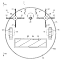
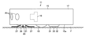
- the vacuum cleaner 11 includes a hollow main body case 15, an electric blower 16 that is an operation unit accommodated in the main body case 15, and a dust collecting portion 17 that communicates with the suction side of the electric blower 16.
- a side brush 21 as a pair of auxiliary cleaning parts (swivel cleaning part) attached so as to be turnable on the surface F
- a turning motor 22 as a turning drive means (swivel drive part) for driving the side brushes 21 respectively.
- Obstacle detection means for detecting obstacles such as walls and furniture, and first transmission as traveling body side transmission means (running body side transmission section) for transmitting signals to charger 12 by infrared rays or the like Part (vacuum side transmitter) 24, charger 12 and remote control (not shown)
- a first receiving unit (cleaner side receiving unit) 25 which is a traveling body side receiving means (running body side receiving unit) for receiving a signal transmitted by infrared rays, etc., a first transmitting unit 24, a first receiving unit 25,
- a first control unit (cleaner side control unit) 26 that is a motor control unit (motor control unit) as a transmission control unit (transmission control unit) that controls driving of the electric blower 16 and each motor 19 and the power supply unit
- a secondary battery 27 which is a constituent battery.
- the direction along the traveling direction of the vacuum cleaner 11 is the front-rear direction (arrows FR and RR shown in FIG. 2 and the like), and the left-right direction intersecting (orthogonal) with the front-rear direction. (Both sides direction) is described as the width direction.
- the main body case 15 is formed in a flat cylindrical shape (disk shape), for example, with synthetic resin, etc., and a suction port 31 as a dust collection port communicating with the dust collection unit 17 is provided on the floor surface of the circular lower surface 15a. An opening is formed facing F. Although not shown, various operation panels, a display unit, and the like are arranged on the upper portion of the main body case 15.
- the suction port 31 is formed in a longitudinal shape in the left-right direction, that is, in a horizontally long shape, and is opened at a position behind the center portion of the lower surface 15a of the main body case 15 and in the center portion in the left-right direction.
- the suction port 31 is surrounded by a nozzle portion 32 whose outer edge protrudes downward from the lower surface 15a of the main body case 15 on the floor surface F side.
- a rotary brush 33 as a rotary cleaning body is rotatably disposed in the suction port 31.
- the nozzle portion 32 is formed so that the opening area gradually becomes narrower toward the lower side (front end side), and the lower end (front end) defines the front portion and the rear portion of the suction port 31.
- the rotating brush 33 is configured, for example, by attaching a plurality of cleaning body portions protruding in a wall shape in a spiral manner on the outer peripheral surface of a long shaft portion.
- the rotating brush 33 protrudes downward from the suction port 31 to the lower surface 15a of the main body case 15, and the rotating brush 33 has a cleaning body portion positioned on the lower side with the vacuum cleaner 11 placed on the floor F.
- the tip is configured to contact the floor surface F.
- the rotary brush 33 is rotationally driven by a drive motor 34 as a rotary cleaning body drive means (rotary cleaning body drive unit).
- the drive motor 34 is housed inside the main body case 15 and is connected to the rotating brush 33 via a gear mechanism (not shown) as a mechanism portion.
- the electric blower 16 is housed inside the main body case 15 with the suction side facing rearward and the axial direction along the front-rear direction (horizontal direction), for example, and the suction side communicates with the dust collecting portion 17. Yes.
- the electric blower 16 may be unnecessary when dust on the floor surface F can be collected in the dust collecting portion 17 by, for example, rotational driving of the rotary brush 33.
- the dust collecting unit 17 collects dust sucked from the suction port 31 by driving the electric blower 16, and is located, for example, at the rear part of the main body case 15.
- Each drive wheel 18 travels (mainly travels) the main body case 15 (the vacuum cleaner 11) on the floor surface F, that is, for travel, and has a flat axis having a rotation axis (not shown) along the left-right width direction. It is formed in a disk shape. Further, these drive wheels 18 are arranged at positions near the center in the front-rear direction at the lower part of the main body case 15 and are spaced apart from each other in the width direction on both sides of the suction port 31. It has become.
- Each motor 19 is disposed, for example, corresponding to each of the driving wheels 18, and can drive each driving wheel 18 independently. These motors 19 may be directly connected to each driving wheel 18 or may be connected to each driving wheel 18 via transmission means (transmission unit) (not shown) such as a gear or a belt.
- transmission unit transmission unit
- the swivel wheel 20 is located at a substantially central portion in the width direction of the main body case 15 and in front of the front wheel, that is, the drive wheel 18, and can swivel along the floor surface F so as to be in contact with the floor surface F. Is a driven wheel that rotates in the advancing direction of the main body case 15.
- Each side brush 21 includes a hub part 36 that is a cleaning part main body as a swivel main part, and brush hairs 37 as a plurality of cleaning bodies that protrude radially from the hub part 36 and come into contact with the floor surface F. Respectively.
- the side brushes 21 and 21 are arranged at positions on both sides of the lower part of the main body case 15 in front of the drive wheels 18 and 18 and behind the swivel wheel 20.
- the hub portion 36 is a pivot shaft whose central portion is pivotally supported on the lower surface 15a of the main body case 15 so as to be pivotable.
- each brush bristle 37 is formed in a linear shape by a member such as a synthetic resin having flexibility (elasticity), for example, protrudes radially from the outside of the hub part 36, and by rotation (turning) of the hub part 36 It rotates integrally with the hub portion 36 to scrape off dust on the floor surface F.
- a member such as a synthetic resin having flexibility (elasticity), for example, protrudes radially from the outside of the hub part 36, and by rotation (turning) of the hub part 36 It rotates integrally with the hub portion 36 to scrape off dust on the floor surface F.
- Each turning motor 22 has a rotating shaft (not shown) projecting downward connected to each hub portion 36, and each side brush 21 is moved to the center side in the width direction of the main body case 15, in other words, the right side brush 21. To the left side, and the left side brush 21 to the right side, that is, each side brush 21 can rotate so as to scrape dust to the suction port 31 side.
- the obstacle detection means 23 is a non-contact sensor such as an ultrasonic sensor, an infrared sensor, or an image sensor, for example, and is disposed over the front or both sides of the outer periphery of the main body case 15, for example. The presence or absence of obstacles (walls) and side obstacles (walls), the distance between them and the main body case 15 can be detected.
- the first transmitting unit 24 is a light emitting unit (light emitting unit) that is a transmitting unit (transmitting unit) such as an infrared light emitting diode, and a transmission directivity setting unit such as a lens that sets the directivity width of light emitted from the light emitting unit. (Transmission directivity setting unit). And this 1st transmission part 24 is electrically connected with the 1st control part 26, for example, the 1st identification information (vacuum cleaner side identification) which is the traveling body side identification information produced
- a directivity D1 having a relatively narrow predetermined width (for example, an acute angle range).
- the signal including the first identification information is, for example, a signal obtained by modulating and superimposing the first identification information on infrared rays, and the first identification information is that a signal including the information is transmitted from the vacuum cleaner 11. Is the ID of the electric vacuum cleaner 11.
- the 1st transmission part 24 can transmit a signal toward the front from the upper part of the main body case 15, not only the structure arrange
- the first receiving unit 25 is, for example, a light receiving unit (light receiving unit) such as a phototransistor or a photocoupler, and a reception directivity setting unit (reception directivity setting unit) such as a lens for setting a directivity width of light reception by the light receiving unit. And.
- the first receiving unit 25 is electrically connected to the first control unit 26.
- the first receiving unit 25 has a directivity D2 having a wider width (eg, an obtuse angle range) than the directivity D1 of the first transmitting unit 24. Signal from.
- a signal from the charger 12 or a signal from an operation means (remote controller) (not shown) for operating the vacuum cleaner 11 can be received from the front at the upper part of the main body case 15, and the received signal Is output to the first control unit 26.
- the 1st receiving part 25 can receive a signal from the front in the upper part of the main body case 15, not only the structure arrange
- the first control unit 26 includes, for example, a timer (timer) such as a timer, a storage unit (storage unit) such as a memory, and a control unit body such as a microcomputer.
- the electric blower 16, each motor 19, and obstacle detection Means 23, first transmitter 24, first receiver 25, drive motor 34, etc. are electrically connected to the detection result by obstacle detector 23 and the analysis result of the signal received by first receiver 25. Based on this, it is possible to control the driving of the electric blower 16, each motor 19, and the like.
- the secondary battery 27 supplies power to the first control unit 26, the electric blower 16, each motor 19, the obstacle detection means 23, the first transmission unit 24, the first reception unit 25, the drive motor 34, and the like. .
- the secondary battery 27 is electrically connected to, for example, charging terminals 39 and 39 located on the lower surface 15a of the main body case 15, and the charging terminals 39 and 39 are electrically connected to the charger 12.
- the secondary battery 27 can be charged by being connected.
- the charger 12 includes a charger main body 41 which is a marker main body, connection terminals 42 and 42 provided in the charger main body 41, a charging circuit 43 for charging the secondary battery 27, and the vacuum cleaner 11.
- Marker receiving means (marker side receiving section) 44 for receiving signals transmitted by infrared rays from the second receiving section (charger side receiving section) 44, marker for transmitting signals to the vacuum cleaner 11 by infrared rays, etc.
- Second transmission unit (charger side transmission unit) 45 which is a side transmission unit (marker side transmission unit), and marker side control unit (marker side control unit) which controls driving of the second transmission unit 45 and the like.
- 2 control unit (charger side control unit) 46 which is a side transmission unit (marker side transmission unit), and marker side control unit (marker side control unit) which controls driving of the second transmission unit 45 and the like.
- connection terminals 42 and 42 are electrically connected to the charging circuit 43, exposed to the outside of the charger body 41, and can be mechanically and electrically connected to the charging terminals 39 and 39 of the vacuum cleaner 11. ing.
- the charging circuit 43 is accommodated in the charger main body 41, and is electrically connected to, for example, a commercial AC power source e that is an external power source, and is connected to the secondary battery 27 through the connection terminals 42 and 42. Is a constant current circuit for charging the secondary battery 27 with a constant current.
- the second receiving unit 44 includes, for example, a light receiving unit (light receiving unit) such as a phototransistor or a photocoupler, and a reception directivity setting unit (reception directivity setting unit) such as a lens for setting a directivity width of light received by the light receiving unit. And.
- the second receiving unit 44 is electrically connected to the second control unit 46.
- the second receiving unit 44 has a wider directivity D3 than the directivity D1 of the first transmission unit 24 (for example, an obtuse angle range). Can be received at a position above the charger main body 41, and the received signal is output to the second control unit 46.
- the 2nd receiving part 44 can receive a signal from the front in the upper part of the charger main body 41, it will receive not only the structure arrange
- the second transmitting unit 45 includes a light emitting unit (light emitting unit) that is a transmitting unit (transmitting unit) such as an infrared light emitting diode, and a transmission directivity setting unit such as a lens that sets the directivity width of light emitted from the light emitting unit. (Transmission directivity setting unit).
- the second transmission unit 45 is electrically connected to the second control unit 46.
- second identification information charger side identification
- marker side identification information generated by the second control unit 46 is used.
- Signal can be transmitted from the upper part of the charger main body 41 in the front direction with the directivity D4 having a width (for example, an obtuse angle range) wider than the directivity D1 of the first transmission unit 24.
- the signal including the second identification information is, for example, a signal obtained by modulating and superimposing the second identification information on infrared rays.
- the second identification information indicates that the signal including this information is transmitted from the charger 12. In other words, the ID of the charger 12 is shown.
- the second transmission unit 45 and the first transmission unit 24 are configured to transmit signals in a time-division manner to each other so that these signals can be separated and identified without interference.
- the 2nd transmission part 45 can transmit a signal toward the front from the upper part of the charger main body 41, not only the structure by which the whole is arrange
- the directivity D3 of the second receiver 44 and the directivity D4 of the second transmitter 45 may be the same width or different widths, and the directivity D2 of the first receiver 25 of the vacuum cleaner 11 Wide or narrow.
- the second control unit 46 includes, for example, a clocking means (timer unit) such as a timer, a storage unit (storage unit) such as a memory, and a control unit main body such as a microcomputer, and includes a charging circuit 43, a second receiving unit 44, and Based on the analysis result of the signal received by the second receiver 44 and electrically connected to the second transmitter 45 and the like, the driving of the second transmitter 45 and the like can be controlled.
- a clocking means timer unit
- storage unit storage unit
- control unit main body such as a microcomputer
- the first control unit 26 operates the electric blower 16, each turning motor 22 (each side brush 21), and the drive motor 34 (rotating brush). 33) is driven, and cleaning is started from the charger 12, for example.
- the cleaning start position can be set at an arbitrary place such as the travel start position of the electric vacuum cleaner 11 or the entrance / exit of the room.
- the first control unit 26 drives the motors 19 and 19 to rotate and autonomously travels on the floor surface F by the drive wheels 18 and 18.
- the first control unit 26 detects, for example, a distance from the wall surrounding the periphery of the cleaning region or an obstacle in the cleaning region via the obstacle detection means 23, or via a step sensor (not shown).
- the position and running state of the vacuum cleaner 11 are monitored, and in response to detection from the obstacle detection means 23 and the step sensor, obstacles can be avoided and steps Run on the floor F while getting over.
- the vacuum cleaner 11 causes the dust on the floor F collected by the side brushes 21 together with the air through the suction port 31 through which the negative pressure generated by the driving of the electric blower 16 acts via the dust collecting unit 17. Suction and scrape up to the dust collecting unit 17 by the rotating brush 33. The dust is separated and collected by the dust collecting unit 17, and the air from which the dust has been separated is sucked into the electric blower 16, and after cooling the electric blower 16, it becomes exhaust air and enters the main body case 15. The air is exhausted from an exhaust port (not shown) provided.
- the first control unit 26 causes the electric vacuum cleaner 11 to autonomously travel to the position of the charger 12. At this time, the first control unit 26 controls the driving of the motors 19 and 19 to turn the body case 15 by a predetermined angle (super turning) to change the direction and to transmit the signal by the first transmission unit 24.
- the first receiving unit 25 sequentially receives signals in a plurality of directions and makes one turn, thereby identifying the direction of the charger 12 with respect to the current position of the vacuum cleaner 11 (main body case 15).
- the main body case 15 (the electric vacuum cleaner 11) is caused to travel based on the direction in which the signal including the identification information is transmitted.
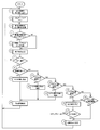
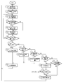
- the first control unit 26 sets the output intensity (signal level) of the signal transmitted from the first transmission unit 24 to a predetermined value, for example, 3 (step 1).
- the first control unit 26 clears the stored reception table (step 2), and transmits a signal including the first identification information from the first transmission unit 24 (step 3).
- the reception table refers to the second identification information transmitted from the second transmitter 45 of the charger 12 at a predetermined angle, for example, in a clockwise direction with respect to the front of the vacuum cleaner 11, for example, in a clockwise direction.
- 6 is a table that stores whether or not a signal including the signal is received by the first receiving unit 25; In this embodiment, it is determined whether or not the signal is received by the first receiver 25 while turning the vacuum cleaner 11 by 10 ° clockwise, so that the reception table is 10 °, 20 °,. This is a table for storing results (numerical values) corresponding to 36 angles of 360 ° (0 °) independently.
- the 1st control part 26 judges whether the signal containing the 2nd identification information transmitted from the 2nd transmission part 45 of the charger 12 by the 1st receiving part 25 was received (step 4). That is, the charger 12 transmits the signal including the second identification information from the second transmission unit 45 only when the signal including the first identification information is received by the second reception unit 44.
- the vacuum cleaner 11 It is possible to determine whether or not the charger 12 is positioned approximately in front of (a direction in which a signal including the first identification information is substantially transmitted).
- Step 4 If it is determined in step 4 that a signal has been received, the first control unit 26 records that the signal has been received as a numerical value in the reception table corresponding to the current turning angle of the vacuum cleaner 11 (Ste 5 (hereinafter referred to as reception recording) proceeds to Step 6. If the first control unit 26 determines in step 4 that no signal has been received, the process proceeds to step 6 as it is.
- the first control unit 26 controls the driving of the motors 19 and 19 to turn the main body case 15 in a predetermined direction, for example, rightward (clockwise direction), by a predetermined angle, for example, 10 ° (step 6).
- the first control unit 26 determines whether or not the main body case 15 has turned 360 ° (step 7). If the first control unit 26 determines in step 7 that the vehicle has not turned 360 °, the process returns to step 3. If it is determined in step 7 that the vehicle has made a 360 ° turn, the first control unit 26 refers to the reception table and determines whether the reception record corresponding to each turn angle is recorded in only one turn angle. (Step 8). In Step 8, when it is determined that the reception record is only one turning angle, it is determined that the charger 12 is positioned in that direction, and the first control unit 26 determines that the main body case 15 Is turned to the angle (step 9), moved forward in that direction by a predetermined distance (step 10), and the process returns to step 1.
- step 8 determines whether the reception record is not only one turning angle. If it is determined in step 8 that the reception record is not only one turning angle, the first control unit 26 determines whether the reception record is continuous at two turning angles in the reception table ( Step 11). If it is determined in step 11 that the reception record is continuous at two turning angles, it is determined that the charger 12 is positioned in the middle of those directions, and the first control unit 26 The main body case 15 is turned to an intermediate angle between the turning angles (step 12), and the process proceeds to step 10.
- step 11 determines whether the reception record is continuous at two turning angles. Judgment is made (step 13). In this step 13, when it is determined that the reception records are continuous at three turning angles, it is determined that the charger 12 is located in the middle of those directions, and the first control unit 26 The main body case 15 is turned to an intermediate angle between the turning angles (step 14), and the process proceeds to step 10.
- the first control unit 26 determines whether the reception record is continuous at four or more turning angles in the reception table. Judgment is made (step 15). If it is determined in step 15 that the reception record is continuous at four or more turning angles, the signal transmitted from the first transmitter 24 of the vacuum cleaner 11 is used as the second receiver of the charger 12. The first control unit 26 determines that the first control unit 26 includes the case where the second reception unit 44 receives the signal directly received by the second reception unit 44 and the signal reflected by a wall or an obstacle disposed in the cleaning area. Decreases the output intensity of the signal transmitted from the first transmitter 24 by a predetermined amount, for example, 1 (step 16).
- the process of step 16 reduces the output intensity of the signal transmitted from the first transmission unit 24, so that the signal intensity when the signal is reflected by a wall or an obstacle is reflected by the second reception unit 44.
- the signal is not limited to a wall or an obstacle. It is intended that the relative positional relationship between the vacuum cleaner 11 and the charger 12 is made clearer by suppressing reflection by the second receiving unit 44 and indirect reception by the second receiving unit 44.
- the first control unit 26 determines whether or not the output intensity of the signal transmitted from the first transmission unit 24 has become 0 (step 17). If the first control unit 26 determines in step 17 that the signal output intensity is not 0, the process returns to step 2. In step 17, when the first control unit 26 determines that the output intensity of the signal has become 0, the specification of the direction of the charger 12 with respect to the vacuum cleaner 11 is temporarily suspended, and the main body is moved to an arbitrary direction. After running the case 15 (step 18), the process returns to step 1.
- Step 19 it is determined whether the reception record exists at a plurality of discontinuous turning angles in the reception table. If it is determined in step 19 that the reception records exist at a plurality of discontinuous turning angles, the signal transmitted from the first transmission unit 24 of the vacuum cleaner 11 is received by the second reception of the charger 12. It is determined that the signal is received directly by the unit 44 and the case where the second receiver 44 receives a signal reflected by a wall or an obstacle arranged in the cleaning area, and the process proceeds to step 16 . If it is determined in step 19 that reception records do not exist at a plurality of discontinuous turning angles, the process proceeds to step 18.
- the electric vacuum cleaner 11 returns to the charger 12 in a stepwise manner by alternately repeating transmission / reception of signals and traveling in this manner.
- the vacuum cleaner 11 that has returned to the position of the charger 12 stops the electric blower 16 and the like, and connects the charging terminals 39 and 39 (mechanically and electrically) to the connection terminals 42 and 42 of the charger 12. Then, the motors 19 and 19 are stopped, the operation is terminated, and the secondary battery 27 is charged.
- the first controller 26 controls the driving of the motors 19 and 19 to change the direction of the main body case 15 (turn the main body case 15).
- the first controller 26 controls the driving of the motors 19 and 19 to change the direction of the main body case 15 (turn the main body case 15).
- the vacuum cleaner 11 when the vacuum cleaner 11 travels a predetermined distance based on the signal transmitted from the second transmitter 45 of the charger 12, the signal is transmitted from the first transmitter 24 again.
- the main body case 15 is not turned around the entire circumference and a signal is transmitted from the first transmission unit 24 at each turning angle, but the main body case 15 is set only at an angle located in the vicinity of the traveling direction including the traveling direction. You may make it transmit by turning. That is, when the electric vacuum cleaner 11 is caused to travel back to the charger 12, when the electric vacuum cleaner 11 has traveled once by receiving a signal transmitted from the second transmitter 45 of the charger 12, the travel is performed.
- the main body case 15 Since it is determined that the charger 12 exists on the direction side and the charger 12 does not exist on the opposite side or the like, the main body case 15 is swung only to the side where the charger 12 is determined to exist and the first case is turned. By transmitting a signal from the transmission unit 24, unnecessary signal transmission and traveling control (turning) of the main body case 15 can be omitted, and the battery 12 can be returned to the charger 12 in a shorter time.
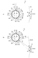
- a plurality of first transmission units 24 and a plurality of first reception units 25 of the first embodiment are arranged in the main body case 15, and the first control unit 26 includes the first transmission unit 24.
- the first receiver 25 sequentially transmits and receives signals around the body case 15 in a plurality of directions.
- the first transmission unit 24 can transmit a signal from a position around the upper part of the main body case 15, that is, at a predetermined angle in the circumferential direction, for example, every 10 °.
- the first receiving unit 25 can receive signals at the periphery of the upper portion of the main body case 15, that is, at a position spaced apart by a predetermined angle in the circumferential direction.
- the first receiving unit 25 may receive signals from the entire circumference of the main body case 15. That is, the directivity D2 of the first receiving unit 25 has a wider range of directivity than the directivity D1 of the first transmitting unit 24. Therefore, the number of the arranged directing units D2 may be smaller than that of the first transmitting unit 24. Therefore, the reception table stored in the first control unit 26 is set so as to cover 360 ° for the plurality of first reception units 25 as a whole.
- the first control unit 26 transmits a signal including the first identification information from any of the first transmission units 24 (step 21), and is transmitted from the second transmission unit 45 of the charger 12 by the first reception unit 25. It is determined whether or not a signal including the second identification information is received (step 22). If it is determined in step 22 that the signal has been received, the first control unit 26 sends the signal to the reception table corresponding to the angle of the first transmission unit 24 that transmitted the signal with respect to the front of the vacuum cleaner 11. The fact that it has been received is recorded (step 23, reception recording), and the process proceeds to step 24. If the first control unit 26 determines in step 22 that no signal has been received, the process proceeds to step 24 as it is.
- the first control unit 26 causes the first transmission unit 24 that transmits a signal next to the first transmission unit 24 that transmitted the signal in step 21 to be adjacent to the first transmission unit 24 in the predetermined direction, for example, the clockwise direction. Switch to the transmitter 24 (step 24).
- the first control unit 26 has returned to the first transmission unit 24 that transmitted the signal first, or in other words, transmitted signals from all the first transmission units 24. It is determined whether or not (whether or not the first transmission unit 24 that transmits a signal makes one round) (step 25). If the first control unit 26 determines in step 25 that signals are not transmitted from all the first transmission units 24, the process returns to step 21. In step 25, if the first control unit 26 determines that signals have been transmitted from all the first transmission units 24, the process proceeds to step 8.
- a plurality of the first transmission units 24 and the first reception units 25 are arranged in the main body case 15, and the first control unit 26 is arranged around the main body case 15 by the first transmission unit 24 and the first reception unit 25.
- the signal when the vacuum cleaner 11 travels a predetermined distance based on the signal transmitted from the second transmitter 45 of the charger 12, the signal is transmitted from the first transmitter 24 again.
- the signal may be transmitted not only from all the first transmission units 24 but only from the first transmission unit 24 located in the vicinity of the traveling direction including the traveling direction. That is, when the electric vacuum cleaner 11 is caused to travel back to the charger 12, when the electric vacuum cleaner 11 has traveled once by receiving a signal transmitted from the second transmitter 45 of the charger 12, the travel is performed. Since it is determined that the charger 12 is present on the direction side and the charger 12 is not present on the opposite side, the signal is transmitted only from the first transmitter 24 located on the side where the charger 12 is determined to be present. Thus, unnecessary signal transmission and control can be omitted, and the battery 12 can be returned to the charger 12 in a shorter time.
- the output intensity of the signal transmitted from the first transmission unit 24 is reduced to suppress indirect reception of this signal by the second reception unit 44.
- the signal is received by the second reception unit 44. Even if the signal reception sensitivity is lowered, the same effect can be obtained.
- the reception sensitivity of the signal received by the first receiving unit 25 is reduced or the second transmitting unit 45 transmits the signal so that indirect reception by the first receiving unit 25 of the signal transmitted from the second transmitting unit 45 is suppressed. Even if the output intensity of the signal is reduced, the same effect can be obtained.
- the transmission units 24 and 45 and the reception units 25 and 44 may transmit and receive signals using wireless media such as ultrasonic waves and laser beams, for example, other than infrared rays.
- the vacuum cleaner 11 basically travels in the direction in which the signal from the second transmitter 45 is received.
- the traveling direction is a direction at a predetermined angle with respect to the reception direction. As long as the traveling direction has a predetermined relationship, the receiving direction and the traveling direction do not necessarily match.
- the present invention can also be applied to a self-propelled device configured as described above.
- a self-propelled device configured as described above.
- a vehicle equipped with an imaging means (camera) as a traveling body
- a user issues a command to the marker from a portable terminal or the like from outside, and the traveling body is guided to a predetermined position by the marker.
- It can also be used as a self-propelled device for indoor monitoring, such as for taking pictures of the camera.
- transmission control means transmission control section
- motor control means motor control section
- the signal including the first identification information is transmitted by the first transmission unit 24 of the vacuum cleaner 11 with the directivity D1 having a predetermined width, and this signal is transmitted to the second of the charger 12. Only when the signal is received by the receiver 44, the signal including the second identification information is transmitted from the second transmitter 45, so that the signal including the second identification information is constantly transmitted from the second transmitter 45. Thus, it is difficult to block other signals from the operation means (remote controller) received by the first receiver 25 by the signal transmitted from the second transmitter 45, for example. That is, signal interference to the vacuum cleaner 11 is unlikely to occur due to the signal transmitted from the second transmitter 45.
- the signal including the second identification information is received by the first receiving unit 25 having the directivity D2 wider than the directivity D1 of the first transmitting unit 24, the signal including the first identification information is transmitted.
- the first control unit 26 controls the driving of the motors 19 and 19 so that the main body case 15 travels based on the direction, so that the electric vacuum cleaner 11 can be reliably guided by the charger 12, for example, electric The vacuum cleaner 11 and the like can be reliably returned to the charger 12.
- the vacuum cleaner 11 travels in the direction in which the signal including the second identification information transmitted from the second transmission unit 25 is basically received, when returning to the charger 12 There is little useless travel, the capacity of the secondary battery 27 can be used more effectively, and the cleaning time can be taken longer.
- the output intensity of the first transmitting unit 24 is reduced to reduce the vacuum cleaner. It is possible to suppress the second receiver 44 from indirectly receiving the signal transmitted from the first transmitter 24 of 11 and to clarify the relative positional relationship between the vacuum cleaner 11 and the charger 12.
- the transmission units 24 and 45 and the reception units 25 and 44 can be configured with inexpensive parts and the directivities D1 and D4 of the transmission units 24 and 45 can be easily controlled.
- the first transmitter 24 can easily set the narrow directivity D1 using a simple configuration such as a slit.
- the vacuum cleaner 11 can be reliably returned to the charger 12 in order to charge the secondary battery 27 when cleaning is completed.
Landscapes
- Engineering & Computer Science (AREA)
- Physics & Mathematics (AREA)
- Aviation & Aerospace Engineering (AREA)
- Radar, Positioning & Navigation (AREA)
- Remote Sensing (AREA)
- General Physics & Mathematics (AREA)
- Automation & Control Theory (AREA)
- Electromagnetism (AREA)
- Control Of Position, Course, Altitude, Or Attitude Of Moving Bodies (AREA)
- Electric Vacuum Cleaner (AREA)
Abstract
Description
Claims (5)
- 走行体と、
この走行体を誘導するマーカとを具備し、
前記走行体は、
本体ケースと、
この本体ケースに回転可能に設けられ、この本体ケースを走行可能とする駆動輪と、
この駆動輪を回転駆動させるモータと、
走行体側識別情報を含む信号を所定幅の指向性で送信する走行体側送信部と、
信号を前記走行体側送信部の指向性よりも広い指向性で受信可能な走行体側受信部と、
前記走行体側送信部を制御して複数の方向に向けて信号を送信させる送信制御部と、
前記モータの駆動を制御するモータ制御部とを備え、
前記マーカは、
前記走行体側識別情報を含む信号を受信するマーカ側受信部と、
このマーカ側受信部により前記走行体側識別情報を含む信号を受信したときに、マーカ側識別情報を含む信号を送信するマーカ側送信部とを備え、
前記モータ制御部は、前記走行体側受信部により前記マーカ側識別情報を含む信号を受信したときに、前記走行体識別情報を含む信号を送信した方向に基づいて前記本体ケースを走行させるように前記モータの駆動を制御する
ことを特徴とした自走式機器。 - 送信制御部は、モータ制御部であり、モータの駆動を制御して本体ケースの方向を変えることにより走行体側送信部による信号の送信と走行体側受信部による信号の受信とを複数の方向で順次行わせる
ことを特徴とした請求項1記載の自走式機器。 - 走行体側送信部および走行体側受信部は、本体ケースにそれぞれ複数配置され、
送信制御部は、前記走行体側送信部および前記走行体側受信部により前記本体ケースの周囲に複数の方向へと信号の送受信を順次行わせる
ことを特徴とした請求項1記載の自走式機器。 - マーカ側識別情報を含む信号を走行体側受信部が所定以上の複数の方向から受信したときに、走行体側送信部の出力強度と前記走行体側受信部の受信感度との少なくともいずれか一方を低下させる
ことを特徴とした請求項2または3記載の自走式機器。 - 走行体は、二次電池を備えた電気掃除機であり、
マーカは、前記電気掃除機が接続可能で、接続された前記電気掃除機の前記二次電池を充電する充電器である
ことを特徴とした請求項1ないし4いずれか一記載の自走式機器。
Priority Applications (5)
| Application Number | Priority Date | Filing Date | Title |
|---|---|---|---|
| US15/109,354 US10048694B2 (en) | 2014-01-09 | 2015-01-09 | Self-propelled device |
| KR1020167009274A KR101910164B1 (ko) | 2014-01-09 | 2015-01-09 | 자율 주행식 기기 |
| CA2935641A CA2935641C (en) | 2014-01-09 | 2015-01-09 | Self-propelled device |
| EP15735283.2A EP3093728B1 (en) | 2014-01-09 | 2015-01-09 | Self-propelled device |
| CN201580004031.7A CN105900032B (zh) | 2014-01-09 | 2015-01-09 | 自走式设备 |
Applications Claiming Priority (2)
| Application Number | Priority Date | Filing Date | Title |
|---|---|---|---|
| JP2014-002707 | 2014-01-09 | ||
| JP2014002707A JP6453539B2 (ja) | 2014-01-09 | 2014-01-09 | 自走式機器 |
Publications (1)
| Publication Number | Publication Date |
|---|---|
| WO2015105178A1 true WO2015105178A1 (ja) | 2015-07-16 |
Family
ID=53524001
Family Applications (1)
| Application Number | Title | Priority Date | Filing Date |
|---|---|---|---|
| PCT/JP2015/050490 Ceased WO2015105178A1 (ja) | 2014-01-09 | 2015-01-09 | 自走式機器 |
Country Status (7)
| Country | Link |
|---|---|
| US (1) | US10048694B2 (ja) |
| EP (1) | EP3093728B1 (ja) |
| JP (1) | JP6453539B2 (ja) |
| KR (1) | KR101910164B1 (ja) |
| CN (1) | CN105900032B (ja) |
| CA (1) | CA2935641C (ja) |
| WO (1) | WO2015105178A1 (ja) |
Families Citing this family (8)
| Publication number | Priority date | Publication date | Assignee | Title |
|---|---|---|---|---|
| KR101473870B1 (ko) * | 2009-06-19 | 2014-12-18 | 삼성전자 주식회사 | 청소장치 |
| WO2015169382A1 (de) * | 2014-05-08 | 2015-11-12 | Alfred Kärcher Gmbh & Co. Kg | Selbstfahrendes und selbstlenkendes bodenreinigungsgerät und verfahren zum reinigen einer bodenfläche |
| TWM521997U (zh) * | 2015-10-13 | 2016-05-21 | Lumiplus Technology Suzhou Co Ltd | 自走裝置之防掉落系統 |
| CN115089055B (zh) | 2018-07-20 | 2024-02-13 | 尚科宁家运营有限公司 | 用于机器人清洁器的对接站和清洁系统 |
| CN109445429A (zh) * | 2018-10-15 | 2019-03-08 | 电子科技大学 | 自动行驶设备的窄通道进入控制方法 |
| JP7851100B2 (ja) * | 2021-10-19 | 2026-04-24 | Seqsense株式会社 | 移動体装置、移動体装置システム、移動体装置システムの制御方法及びプログラム |
| CN116919264B (zh) * | 2022-03-31 | 2026-02-13 | 深圳银星智能集团股份有限公司 | 清洁机器人和清洁系统 |
| CN115969287B (zh) * | 2023-03-21 | 2023-09-26 | 科大讯飞股份有限公司 | 清洁机器人及其电量管理方法、装置及存储介质 |
Citations (8)
| Publication number | Priority date | Publication date | Assignee | Title |
|---|---|---|---|---|
| JPH06125861A (ja) | 1992-10-20 | 1994-05-10 | Matsushita Electric Ind Co Ltd | 自走式掃除機 |
| JPH07322977A (ja) | 1994-06-01 | 1995-12-12 | Matsushita Electric Ind Co Ltd | 自走式掃除機 |
| JP2000299364A (ja) * | 1999-04-12 | 2000-10-24 | Murata Mach Ltd | 光データ伝送装置及びこれを用いた光データ伝送システム |
| JP2006236109A (ja) * | 2005-02-25 | 2006-09-07 | Sanyo Electric Co Ltd | ロボットの自動充電システム。 |
| JP2006244020A (ja) * | 2005-03-02 | 2006-09-14 | Sanyo Electric Co Ltd | ロボット充電誘導システム |
| JP2007213180A (ja) * | 2006-02-08 | 2007-08-23 | Figla Co Ltd | 移動体システム |
| JP2008102698A (ja) * | 2006-10-18 | 2008-05-01 | Funai Electric Co Ltd | 自走式装置充電システム |
| JP2008181177A (ja) * | 2007-01-23 | 2008-08-07 | Matsushita Electric Ind Co Ltd | 充電池搭載移動体の充電装置 |
Family Cites Families (11)
| Publication number | Priority date | Publication date | Assignee | Title |
|---|---|---|---|---|
| US4679152A (en) * | 1985-02-20 | 1987-07-07 | Heath Company | Navigation system and method for a mobile robot |
| US5165064A (en) * | 1991-03-22 | 1992-11-17 | Cyberotics, Inc. | Mobile robot guidance and navigation system |
| US6532404B2 (en) * | 1997-11-27 | 2003-03-11 | Colens Andre | Mobile robots and their control system |
| WO2004025947A2 (en) * | 2002-09-13 | 2004-03-25 | Irobot Corporation | A navigational control system for a robotic device |
| US7320149B1 (en) | 2002-11-22 | 2008-01-22 | Bissell Homecare, Inc. | Robotic extraction cleaner with dusting pad |
| KR100492590B1 (ko) * | 2003-03-14 | 2005-06-03 | 엘지전자 주식회사 | 로봇의 자동충전 시스템 및 복귀방법 |
| KR100544480B1 (ko) * | 2004-05-12 | 2006-01-24 | 삼성광주전자 주식회사 | 로봇 청소기 |
| KR100738890B1 (ko) * | 2005-07-22 | 2007-07-12 | 엘지전자 주식회사 | 이동로봇을 이용한 홈 네트워킹 시스템 |
| KR20070099359A (ko) * | 2006-04-04 | 2007-10-09 | 삼성전자주식회사 | 로봇청소기와 도킹 스테이션을 구비하는 로봇청소기 시스템 |
| US20080004751A1 (en) * | 2006-06-28 | 2008-01-03 | Samsung Electronics Co., Ltd. | Robot cleaner system and method of controlling the same |
| GB0909148D0 (en) * | 2009-05-28 | 2009-07-01 | F Robotics Acquisitions Ltd | Localisation system |
-
2014
- 2014-01-09 JP JP2014002707A patent/JP6453539B2/ja active Active
-
2015
- 2015-01-09 CA CA2935641A patent/CA2935641C/en not_active Expired - Fee Related
- 2015-01-09 WO PCT/JP2015/050490 patent/WO2015105178A1/ja not_active Ceased
- 2015-01-09 EP EP15735283.2A patent/EP3093728B1/en not_active Not-in-force
- 2015-01-09 CN CN201580004031.7A patent/CN105900032B/zh active Active
- 2015-01-09 US US15/109,354 patent/US10048694B2/en not_active Expired - Fee Related
- 2015-01-09 KR KR1020167009274A patent/KR101910164B1/ko not_active Expired - Fee Related
Patent Citations (8)
| Publication number | Priority date | Publication date | Assignee | Title |
|---|---|---|---|---|
| JPH06125861A (ja) | 1992-10-20 | 1994-05-10 | Matsushita Electric Ind Co Ltd | 自走式掃除機 |
| JPH07322977A (ja) | 1994-06-01 | 1995-12-12 | Matsushita Electric Ind Co Ltd | 自走式掃除機 |
| JP2000299364A (ja) * | 1999-04-12 | 2000-10-24 | Murata Mach Ltd | 光データ伝送装置及びこれを用いた光データ伝送システム |
| JP2006236109A (ja) * | 2005-02-25 | 2006-09-07 | Sanyo Electric Co Ltd | ロボットの自動充電システム。 |
| JP2006244020A (ja) * | 2005-03-02 | 2006-09-14 | Sanyo Electric Co Ltd | ロボット充電誘導システム |
| JP2007213180A (ja) * | 2006-02-08 | 2007-08-23 | Figla Co Ltd | 移動体システム |
| JP2008102698A (ja) * | 2006-10-18 | 2008-05-01 | Funai Electric Co Ltd | 自走式装置充電システム |
| JP2008181177A (ja) * | 2007-01-23 | 2008-08-07 | Matsushita Electric Ind Co Ltd | 充電池搭載移動体の充電装置 |
Non-Patent Citations (1)
| Title |
|---|
| See also references of EP3093728A4 |
Also Published As
| Publication number | Publication date |
|---|---|
| JP2015132892A (ja) | 2015-07-23 |
| JP6453539B2 (ja) | 2019-01-16 |
| CN105900032A (zh) | 2016-08-24 |
| CA2935641A1 (en) | 2015-07-16 |
| US20160324386A1 (en) | 2016-11-10 |
| CA2935641C (en) | 2020-06-02 |
| EP3093728A1 (en) | 2016-11-16 |
| KR20160053997A (ko) | 2016-05-13 |
| KR101910164B1 (ko) | 2018-10-19 |
| EP3093728A4 (en) | 2017-10-11 |
| US10048694B2 (en) | 2018-08-14 |
| CN105900032B (zh) | 2019-06-28 |
| EP3093728B1 (en) | 2020-07-01 |
Similar Documents
| Publication | Publication Date | Title |
|---|---|---|
| JP6453539B2 (ja) | 自走式機器 | |
| KR101939671B1 (ko) | 주행체 장치 | |
| KR101771869B1 (ko) | 주행체 장치 | |
| CN111315275B (zh) | 机器人清洁器及其控制方法 | |
| KR102070066B1 (ko) | 로봇 청소기 및 그 제어 방법 | |
| US10542858B2 (en) | Self-propelled electronic device and travel method for self-propelled electronic device | |
| JP2014226266A (ja) | 電気掃除機 | |
| JP6636289B2 (ja) | 走行体装置 | |
| CN211862703U (zh) | 人工障碍物生成器和自主清洁系统 | |
| JP6382634B2 (ja) | 自律走行体装置 | |
| JP6266331B2 (ja) | 走行体装置 | |
| JP6633152B2 (ja) | 自走式機器 | |
| JP6261977B2 (ja) | 走行体装置 | |
| JP6239971B2 (ja) | 走行体および走行体装置 | |
| JP2016051913A (ja) | 自律走行体装置 | |
| JP2020099461A (ja) | 自律走行型掃除機 | |
| KR100619727B1 (ko) | 로봇 청소기의 주행장치 | |
| JP2017216022A (ja) | 走行体および走行体装置 | |
| JP2017216021A (ja) | 走行体および走行体装置 | |
| JP2017064065A (ja) | ビーコン装置および走行体装置 |
Legal Events
| Date | Code | Title | Description |
|---|---|---|---|
| 121 | Ep: the epo has been informed by wipo that ep was designated in this application |
Ref document number: 15735283 Country of ref document: EP Kind code of ref document: A1 |
|
| ENP | Entry into the national phase |
Ref document number: 20167009274 Country of ref document: KR Kind code of ref document: A |
|
| REEP | Request for entry into the european phase |
Ref document number: 2015735283 Country of ref document: EP |
|
| WWE | Wipo information: entry into national phase |
Ref document number: 2015735283 Country of ref document: EP |
|
| ENP | Entry into the national phase |
Ref document number: 2935641 Country of ref document: CA |
|
| WWE | Wipo information: entry into national phase |
Ref document number: 15109354 Country of ref document: US |
|
| NENP | Non-entry into the national phase |
Ref country code: DE |
|
| REG | Reference to national code |
Ref country code: BR Ref legal event code: B01A Ref document number: 112016015669 Country of ref document: BR |
|
| ENP | Entry into the national phase |
Ref document number: 112016015669 Country of ref document: BR Kind code of ref document: A2 Effective date: 20160705 |