WO2015107572A1 - Dispositif de lecture et d'enregistrement d'informations, et procédé de lecture et d'enregistrement d'informations - Google Patents
Dispositif de lecture et d'enregistrement d'informations, et procédé de lecture et d'enregistrement d'informations Download PDFInfo
- Publication number
- WO2015107572A1 WO2015107572A1 PCT/JP2014/004543 JP2014004543W WO2015107572A1 WO 2015107572 A1 WO2015107572 A1 WO 2015107572A1 JP 2014004543 W JP2014004543 W JP 2014004543W WO 2015107572 A1 WO2015107572 A1 WO 2015107572A1
- Authority
- WO
- WIPO (PCT)
- Prior art keywords
- recording
- signal
- mark
- information
- compensation
- Prior art date
- Legal status (The legal status is an assumption and is not a legal conclusion. Google has not performed a legal analysis and makes no representation as to the accuracy of the status listed.)
- Ceased
Links
Images








Classifications
-
- G—PHYSICS
- G11—INFORMATION STORAGE
- G11B—INFORMATION STORAGE BASED ON RELATIVE MOVEMENT BETWEEN RECORD CARRIER AND TRANSDUCER
- G11B7/00—Recording or reproducing by optical means, e.g. recording using a thermal beam of optical radiation by modifying optical properties or the physical structure, reproducing using an optical beam at lower power by sensing optical properties; Record carriers therefor
- G11B7/004—Recording, reproducing or erasing methods; Read, write or erase circuits therefor
- G11B7/0045—Recording
- G11B7/00456—Recording strategies, e.g. pulse sequences
-
- G—PHYSICS
- G11—INFORMATION STORAGE
- G11B—INFORMATION STORAGE BASED ON RELATIVE MOVEMENT BETWEEN RECORD CARRIER AND TRANSDUCER
- G11B20/00—Signal processing not specific to the method of recording or reproducing; Circuits therefor
- G11B20/10—Digital recording or reproducing
- G11B20/10009—Improvement or modification of read or write signals
-
- G—PHYSICS
- G11—INFORMATION STORAGE
- G11B—INFORMATION STORAGE BASED ON RELATIVE MOVEMENT BETWEEN RECORD CARRIER AND TRANSDUCER
- G11B20/00—Signal processing not specific to the method of recording or reproducing; Circuits therefor
- G11B20/10—Digital recording or reproducing
- G11B20/10009—Improvement or modification of read or write signals
- G11B20/10037—A/D conversion, D/A conversion, sampling, slicing and digital quantisation or adjusting parameters thereof
-
- G—PHYSICS
- G11—INFORMATION STORAGE
- G11B—INFORMATION STORAGE BASED ON RELATIVE MOVEMENT BETWEEN RECORD CARRIER AND TRANSDUCER
- G11B20/00—Signal processing not specific to the method of recording or reproducing; Circuits therefor
- G11B20/10—Digital recording or reproducing
- G11B20/10009—Improvement or modification of read or write signals
- G11B20/10046—Improvement or modification of read or write signals filtering or equalising, e.g. setting the tap weights of an FIR filter
- G11B20/10194—Improvement or modification of read or write signals filtering or equalising, e.g. setting the tap weights of an FIR filter using predistortion during writing
-
- G—PHYSICS
- G11—INFORMATION STORAGE
- G11B—INFORMATION STORAGE BASED ON RELATIVE MOVEMENT BETWEEN RECORD CARRIER AND TRANSDUCER
- G11B7/00—Recording or reproducing by optical means, e.g. recording using a thermal beam of optical radiation by modifying optical properties or the physical structure, reproducing using an optical beam at lower power by sensing optical properties; Record carriers therefor
- G11B7/004—Recording, reproducing or erasing methods; Read, write or erase circuits therefor
- G11B7/0045—Recording
-
- G—PHYSICS
- G11—INFORMATION STORAGE
- G11B—INFORMATION STORAGE BASED ON RELATIVE MOVEMENT BETWEEN RECORD CARRIER AND TRANSDUCER
- G11B7/00—Recording or reproducing by optical means, e.g. recording using a thermal beam of optical radiation by modifying optical properties or the physical structure, reproducing using an optical beam at lower power by sensing optical properties; Record carriers therefor
- G11B7/004—Recording, reproducing or erasing methods; Read, write or erase circuits therefor
- G11B7/006—Overwriting
- G11B7/0062—Overwriting strategies, e.g. recording pulse sequences with erasing level used for phase-change media
-
- G—PHYSICS
- G11—INFORMATION STORAGE
- G11B—INFORMATION STORAGE BASED ON RELATIVE MOVEMENT BETWEEN RECORD CARRIER AND TRANSDUCER
- G11B7/00—Recording or reproducing by optical means, e.g. recording using a thermal beam of optical radiation by modifying optical properties or the physical structure, reproducing using an optical beam at lower power by sensing optical properties; Record carriers therefor
- G11B7/12—Heads, e.g. forming of the optical beam spot or modulation of the optical beam
- G11B7/125—Optical beam sources therefor, e.g. laser control circuitry specially adapted for optical storage devices; Modulators, e.g. means for controlling the size or intensity of optical spots or optical traces
- G11B7/126—Circuits, methods or arrangements for laser control or stabilisation
- G11B7/1263—Power control during transducing, e.g. by monitoring
-
- G—PHYSICS
- G11—INFORMATION STORAGE
- G11B—INFORMATION STORAGE BASED ON RELATIVE MOVEMENT BETWEEN RECORD CARRIER AND TRANSDUCER
- G11B7/00—Recording or reproducing by optical means, e.g. recording using a thermal beam of optical radiation by modifying optical properties or the physical structure, reproducing using an optical beam at lower power by sensing optical properties; Record carriers therefor
- G11B7/12—Heads, e.g. forming of the optical beam spot or modulation of the optical beam
- G11B7/125—Optical beam sources therefor, e.g. laser control circuitry specially adapted for optical storage devices; Modulators, e.g. means for controlling the size or intensity of optical spots or optical traces
- G11B7/126—Circuits, methods or arrangements for laser control or stabilisation
- G11B7/1267—Power calibration
Definitions
- the present disclosure relates to an information recording / reproducing apparatus that performs recording compensation for realizing high-density recording more stably with respect to an information recording medium having an information recording surface on which information can be optically recorded, and information
- the present invention relates to a recording / reproducing method.
- BD Blu-ray (registered trademark) Disc
- the data archiver is a product that is mainly sold for business use, and it is necessary to further increase the density so that more data can be stored.
- the information recording medium records information by forming recording marks and spaces in the recording layer of the information recording medium.
- Reproduction of the information recording medium irradiates the recording mark and space formed on the recording layer with laser light having low output power, and obtains a reproduction signal from the difference between the optical characteristics of the recording mark and space, for example, the reflectance.
- the recorded information is reproduced by processing the reproduction signal.
- Recording on the information recording medium is performed by irradiating the recording layer with a recording pulse obtained by modulating the intensity of laser light based on information to be recorded, thereby recording a recording mark.
- An information recording / reproducing apparatus that performs recording / reproduction of an information recording medium performs recording compensation that adjusts the start edge position and the end edge position of the record mark so as to reduce errors in a reproduction signal obtained by reproducing the recorded record mark.
- Recording compensation is particularly required at recording densities where the length of the space between recording marks is short.
- the heat at the time of forming the recording mark is not sufficiently reduced in the space portion, which affects the temperature rise at the starting edge of the rear recording mark.
- the heat at the beginning of the rear recording mark affects the cooling of the heat at the end edge of the front recording mark.
- thermal interference which depends on the length of the space.
- the pulse shape of the recording laser is finely adjusted according to the length of the space in order to correct the edge position of the recording mark that fluctuates due to thermal interference.
- the amplitude of the reproduction signal becomes small, and further, due to the influence of code interference, a difference occurs in the reproduction signal depending on the combination of the recording mark and space. For example, even with the same recording mark length, the reproduction signal at the edge portion of the recording mark is detected differently due to the difference in the front and back space lengths. Therefore, it is effective to apply a PRML (Partial Response Maximum Likelihood) method or the like as a reproduction signal processing method. Recording compensation can be performed more accurately by equalizing the waveform of the reproduced signal by the PRML method and reducing the influence of intersymbol interference.
- PRML Physical Response Maximum Likelihood
- Patent Document 1 discloses an example of a method for detecting an edge shift, which is a shift in the edge position of a recording mark, in order to perform recording compensation by equalizing a reproduced signal in the PRML method.
- Patent Document 1 attention is paid to the edge of the recording mark in the maximum likelihood bit string obtained by decoding the reproduction signal by the PRML method, and the bit of the maximum likelihood bit string is shifted at the edge portion, or the maximum likelihood bit string of the entire recording mark including the edge portion is changed.
- An error bit string which is the most error-prone bit string in which bits are shifted, is generated, and edge shift is evaluated based on the maximum likelihood bit string and the difference in Euclidean distance between each target signal corresponding to the error bit string and the reproduced signal.
- recording compensation at a recording density of about 31 GB in BD is performed by using a reproduction signal at the edge portion of the own mark, which is a recording mark to be recorded, or a reproduction signal up to a space length adjacent to the recording mark. It is possible to directly detect the edge shift of the edge portion.
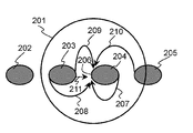
- FIG. 2 is a diagram for explaining the interference of the edge shift of the edge portion of the recording mark.
- the recording marks 203, 204, and 205 exist within the laser light spot 201.
- the edge 206 of the recording mark 203 is a target for which edge shift detection is desired.
- each recording mark includes an edge shift at each edge, and recording is performed as intersymbol interference of other edge shifts with respect to the edge portion 206 of the recording mark 204.
- intersymbol interference 207 of the mark 204 intersymbol interference 208 and 209 of the recording mark 203, and intersymbol interference 210 of the recording mark 205.
- the thermal interference 211 of the recording mark 203 exists as thermal interference with the edge portion 206 of the recording mark 204.
- the edge shift detection range is a range up to the front and rear spaces.
- the edge shift of the recording mark to be detected is related to the length of the front and rear spaces, but is not related to the length of the front and rear recording marks.
- recording compensation can be appropriately performed by detecting an edge shift as in Patent Document 1.
- the conventional edge shift detection cannot be detected with high accuracy. This is because the range of the intersymbol interference and the thermal interference is widened and the signal band of the reproduction signal is used in a range exceeding the optical resolution.
- the amplitude of the reproduced signal decreases as the length of the space between the recording marks and the recording marks decreases, and the optical resolution When the value exceeds, the amplitude of the reproduction signal becomes zero.
- the reciprocal of the repetition period of the space between recording marks corresponding to the same channel clock length is called the spatial frequency.
- the transfer function of the spatial frequency is called OTF (Optical Transfer Function).
- a function representing the amplitude dependence of the OTF on the spatial frequency is referred to as MTF (Modulation Transfer Function).
- the condition that the amplitude of the reproduction signal becomes zero is that when the laser wavelength ⁇ and the numerical aperture NA (Numerical Aperture) of the objective lens are set, the length L of the space between the recording marks and the recording marks is ⁇ / (4 ⁇ NA) is the case below.
- NA numerical aperture
- the length L is about 119.1 nm. This corresponds to a recording density of about 31 GB when the disk structure is the same. Therefore, in recording with a recording density of about 31 GB, the amplitude of the continuous signal with the shortest run length is zero.
- the spatial frequency of the MTF shifts to a lower frequency side than the signal band, so that there is a spatial frequency with no signal amplitude.
- Patent Document 1 when “011000” is included in the maximum likelihood bit string in one of the edge detections, a right-shifted bit string bit-shifted to the right is generated from the mask bit string “000100” and the maximum likelihood bit string, and is reproduced. An edge shift with respect to the bit string “011000” is detected based on the Euclidean distance difference between the signal, the maximum likelihood bit string, and the right shift bit string.
- one of the edge detections includes “1110001000” in the maximum likelihood bit string
- a right-shifted bit string that is bit-shifted to the right is generated from the mask bit string “0000010100” and the maximum likelihood bit string, and the reproduced signal
- an edge shift with respect to the bit string “111001000” is detected.
- bit string “011000” exists as a common bit string in the bit string “011000” and the bit string “111001000”. That is, two edge shifts are detected for one edge.
- the recording compensation is executed only for the recording condition for one edge, for example, the pulse position and width of the recording pulse. Therefore, it is very difficult to reduce two edge shifts simultaneously by recording compensation.
- the edge shift cannot be properly detected by the conventional method in which the edge shift is detected from the reproduction signal near the edge portion as the recording density exceeds the optical resolution and the recording density becomes higher.
- an object of the present disclosure is to provide an information recording / reproducing apparatus and an information recording / reproducing method for performing appropriate recording compensation.
- an information recording / reproducing apparatus of the present disclosure includes a reproducing unit that generates a digital signal from an analog signal that is information recorded on an information recording medium, and a binary signal that is decoded from the digital signal.
- a recording compensation unit that generates an expected value signal based on the binarized signal, detects a signal difference between the digital signal and the expected value signal, and adjusts a recording condition for recording information on the information recording medium based on the signal difference
- a recording unit for recording information on the information recording medium based on the recording conditions.
- the recording condition is adjusted by using the first recording data in which the length of the space before and after the first recording mark and the length of the space before and after the second recording mark are such that there is no intersymbol interference.
- the first recording compensation for adjusting the condition is executed, and the second recording mark for which the first recording compensation has been executed is arranged in front of or behind the first recording mark for which the first recording compensation has been executed, The length of the space between the first recording mark and the second recording mark is made constant, and the second recording data that changes the length of the second recording mark is used to Second recording compensation is performed to adjust the recording conditions.
- FIG. 1 is a diagram showing an information recording / reproducing apparatus according to the first embodiment.
- FIG. 2 is a diagram for explaining the interference of the edge shift at the edge portion of the recording mark.
- FIG. 3 is a diagram for explaining the recording pulse waveform and the recording power.
- FIG. 4A is a diagram showing recording pulses having a monopulse waveform.
- FIG. 4B is a diagram showing a recording pulse having an L-shaped pulse waveform.
- FIG. 4C is a diagram showing a recording pulse having a Castle-type pulse waveform.
- FIG. 5 is a diagram for explaining an isolated mark and a reproduction signal for performing recording compensation in the first embodiment.
- FIG. 6 is a diagram for explaining an isolated mark whose length is changed and a reproduction signal thereof in the first embodiment.
- FIG. 7A is a diagram for explaining a reproduction signal and an expected value signal when the recording mark in the first embodiment is an isolated mark.
- FIG. 7B is a diagram for explaining a reproduction signal and an expected value signal when there is a recording mark affected by intersymbol interference in front of the recording mark in the first embodiment.
- FIG. 7C is a diagram for explaining a reproduction signal and an expected value signal when the recording mark in Embodiment 1 is further affected by the thermal interference of the front recording mark.
- FIG. 8 is a diagram for explaining recording marks recorded for detecting the influence of thermal interference in the first embodiment.
- FIG. 9 is a diagram for explaining a signal difference with respect to the front recording mark length in the first embodiment.
- FIG. 10A is a diagram showing a recording pulse for performing recording compensation for a recording mark 2T according to the first embodiment.
- FIG. 10B is a diagram showing a recording pulse for performing recording compensation for a recording mark of 4T in the first embodiment.
- FIG. 11 is a diagram showing an example of recording data used for recording compensation in the first embodiment.
- FIG. 12A is a diagram showing a binary signal when the 2T recording mark in the recording pattern B of FIG. 11 is an isolated mark.
- 12B is a diagram illustrating a binary signal when a 4T recording mark is arranged in front of a 2T recording mark in the recording pattern B of FIG.
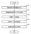
- FIG. 13 is a flowchart for performing recording compensation in the first embodiment.
- FIG. 14 is a flowchart for performing recording compensation at each step in FIG. FIG.
- FIG. 15 shows an information recording / reproducing apparatus according to the second embodiment.
- FIG. 16A is a diagram for explaining the edge shift X of the starting edge in the detection pattern according to the second embodiment.
- FIG. 16B is a diagram for explaining the edge shift X of the terminal edge in the detection pattern according to the second embodiment.
- FIG. 17A is a diagram for explaining the signal difference Y of the start edge in the detection pattern in the second embodiment.
- FIG. 17B is a diagram for explaining the signal difference Y of the trailing edge in the detection pattern in the second embodiment.
- FIG. 18 is a diagram for explaining the addition of the change amount of the isolated waveform at the specific edge portion in the reproduction signal according to the second embodiment.
- FIG. 19 is a flowchart for executing recording compensation of the recording pulse condition in the second embodiment.
- FIG. 20 is a flowchart for explaining the operation of the edge shift detector in the second embodiment.
- the information recording medium according to the embodiment is an information recording medium that performs recording with a BD as a basic configuration and a high recording density.
- the recording density exceeding the optical resolution is about 31 GB or more, but the present disclosure is not limited to the recording density of about 31 GB or more, and can be applied to a recording density less than the optical resolution.
- an RLL (Run Length Limited) code such as an RLL (1, 7) code is used.
- the description will be made assuming that the shortest run length of the modulation code is 2T and the longest run length is 8T. Therefore, the length of 2T, which is the shortest mark and space, is about 119.1 nm or less.
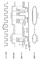
- FIG. 3 is a diagram for explaining the recording pulse waveform and the recording power.
- FIG. 3 a clock signal, an NRZI (Non Return to Zero Inverting) signal, a multi-pass train recording pulse, and a recording mark are shown from the top.
- NRZI Non Return to Zero Inverting
- the clock signal is a cycle Tw of a channel clock that becomes a reference signal when recording data is created, and a time interval between a recording mark and a space of the NRZI signal that is a recording signal is determined by the cycle Tw.
- the NRZI signal indicates a recording pattern of 2T mark-2T space-4T mark as a partial example.
- the multi-pass train is a multi-pulse train of laser light for forming recording marks.
- the recording power Pw of the multi-pulse train is composed of a peak power Pp301 having a heating effect, a bottom power Pb302 having a cooling effect and a cooling power Pc303 necessary for forming a recording mark, and a space power Ps304 which is a recording power in the space portion.
- the peak power Pp301, the bottom power Pb302, the cooling power Pc303, and the space power Ps304 are set with respect to the extinction level 305 detected when the laser beam is extinguished.
- the level of each recording power may be set according to the recording mark length.
- the leading pulse width Ttop is set for recording signals of 2T, 3T, 4T, and 5T or more.
- the pulse width Tmp after Ttop existing in a multi-pulse train of 3T or more is set to be the same, and the final pulse width Tmp is set as the last pulse width Tlp.
- the last pulse width Tlp is set for recording signals of 3T, 4T, and 5T or more.
- a recording start position offset dTtop for adjusting the start position of the recording mark and a recording end position offset dTs for adjusting the end position are set.
- Recording compensation in the embodiment means that the recording parameters (Ttop, dTtop, etc.) of the recording pulse are adjusted to the optimum recording conditions for each recording mark.
- changing the recording parameter of the recording pulse in accordance with the length of the front space or the rear space in the recording mark for recording compensation is called space compensation.
- the recording conditions which are recording parameters such as each value of the recording power of the multi-pulse train and the pulse width, are described inside the information recording medium.
- the recording apparatus that records the information recording medium may acquire the unique information of the information recording medium and record it using the recording conditions stored in advance in the recording apparatus.
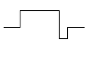
- FIG. 4A As the recording pulse shape, there are recording pulse shapes as shown in FIG. 4A, FIG. 4B, and FIG. 4C in addition to the waveform of the multi-pulse train of FIG. 4A shows a monopulse waveform
- FIG. 4B shows an L-shaped pulse waveform
- FIG. 4C shows a recording pulse of a Castle-type pulse waveform.
- Each recording pulse waveform has a different amount of heat accumulated in the recording layer of the information recording medium. Therefore, in order to form an optimum recording mark, a recording pulse shape corresponding to the film characteristics of the recording layer is selected.
- the length of the space is a length that does not affect the intersymbol interference of the preceding and following recording marks.
- the space length ( ⁇ / (4 ⁇ NA)) ⁇ N that is N times the space length ⁇ / (4 ⁇ NA), where N is a condition that makes the amplitude of the reproduced signal zero.
- a recording mark positioned between the front and rear spaces set so as not to interfere with the edge shift of other recording marks is defined as an isolated mark.
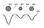
- FIG. 5 is a diagram for explaining an isolated mark for performing recording compensation and a reproduction signal.
- a front recording mark 502, a front space 503, a rear space 504, and a rear recording mark 505 are arranged with respect to the isolated mark 501.
- the reproduction signal 506 is a signal obtained by reproducing the isolated mark 501, the front recording mark 502, the front space 503, the rear space 504, and the rear recording mark 505.
- the front space 503 and the rear space 504 are set to such a length that the front recording mark 502 and the rear recording mark 505 do not interfere with the isolated mark 501.
- the reproduction signal 506 has a level at which the reproduction signal 506 surrounded by the dotted line in FIG. 5 is constant in the front space 503 and the rear space 504.
- This constant level is the same as the level of the reproduction signal when there is no recording mark. More precisely, it is a level of a signal obtained by reproducing a track in a recording area (not shown) after irradiation with the space power Ps304 of the recording power. This means that there is no code interference between the front and rear recording marks. Also, the section at a certain level depends on the length of the space. The longer the space length, the longer the section at a certain level.
- the recording compensation for the isolated mark 501 can be performed without receiving the interference of the edge shift of other recording marks. That is, the edge shift or length and phase with respect to the isolated mark 501 can be detected.
- the front recording mark 502 may interfere with an intersymbol with a further front recording mark (not shown).
- the rear recording mark 505 may have intersymbol interference with a further rear recording mark (not shown).
- the recording data excluding the isolated mark 501 and the space before and after the recording pattern is set as a recording pattern that is easy to perform PLL (Phase Locked Loop) or DC (Direct Current) control.
- the recording pattern is, for example, a single signal or special recording data whose appearance length is limited. This makes it possible to detect the timing of recording compensation, the reproduction signal level, and the like with higher accuracy.
- FIG. 6 is a diagram for explaining an isolated mark whose length is changed and a reproduction signal thereof.
- the isolated marks are arranged with three marks having different lengths.
- the reproduction signal 601 is a signal for these recording data
- the expected value signal 602 is a target signal of the reproduction signal 601 when there is no edge shift of the isolated mark. If the reproduction signal 601 can be matched with the expected value signal 602, it can be decoded as error-free recording data by reproduction signal processing.
- the expected value signal in the present embodiment is a linear signal, and assumes a signal obtained by convolution of a binary signal that is recording data and a response characteristic per 1T (hereinafter referred to as an isolated waveform).
- the isolated waveform is, for example, an MTF characteristic expressed on the time axis, or an equalization coefficient when the reproduction signal is adaptively equalized, for example, PR equalization characteristic in the PRML system. Therefore, the isolated waveform corresponds to a reproduction signal for the recording data 1T.
- the edge of the isolated mark is changed so that the reproduction signal 601 matches the expected value signal 602.
- the edge shift can be detected by, for example, the edge position of the isolated mark or a signal difference such as the difference between the reproduction signal and the expected value signal near the edge position, the Euclidean distance, and the like. Further, the edge shift may be detected as a length shift or a phase shift.
- the difference in length is, for example, the difference between the bottom point of the reproduction signal and the bottom point of the expected value signal at the center position of the isolated mark, or the square sum of the energy of the reproduction signal from a certain level and the expected value signal. It can be detected by energy difference.
- the phase shift can be detected by a shift in the time axis direction between the bottom point of the reproduction signal and the bottom point of the expected value signal, or a cross-correlation that is a value obtained by integrating the reproduction signal and the expected value signal.
- the front space 503 and the rear space 504 have a length that does not appear in the modulation code.
- the effect of thermal interference occurs due to the short space length.
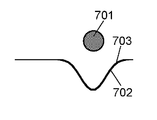
- FIG. 7A shows a reproduction signal 702 and an expected value signal 703 when the recording mark 701 is an isolated mark.
- FIG. 7B shows a reproduction signal 702 and an expected value signal 703 in the case where a recording mark 704 is present in front of the recording mark 701 subjected to recording compensation as an isolated mark.
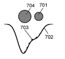
- FIG. 7C shows a reproduction signal 702 and an expected value signal 703 when the recording mark 701 subjected to recording compensation is further affected by the thermal interference of the front recording mark 704.
- the reproduction signal 702 is a solid line, and the expected value signal 703 is a broken line.
- 7B and 7C are diagrams for explaining the influence of optical interference and thermal interference. Since the recording marks 701 and 704 have the same arrangement, the waveforms of the expected value signal 703 in FIGS. 7B and 7C are the same. It is.
- Recording marks 701 and 704 are compensated for recording as isolated marks. That is, the edge shift of the recording marks 701 and 704 is very small. The influence that the edge shift of the recording mark 701 interferes with the recording mark 704 is very small. Conversely, the influence of the edge shift of the recording mark 704 interfering with the recording mark 701 is very small.
- a recording mark 701 is an isolated mark and is compensated for recording. Therefore, the reproduction signal 702 overlaps with the expected value signal 703 almost equally.
- Optical interference refers to a reproduction signal that is reproduced when a recording mark that has been compensated for recording as at least two or more isolated marks is placed within a range where intersymbol interference occurs, and the recorded mark is an isolated mark. This is a phenomenon that does not match the signal obtained by adding the reproduction signal. This is distortion of a reproduction signal generated in a system that irradiates a recording layer with a laser beam through a lens and detects the reproduction signal based on a difference in reflectance. Optical interference was negligible because it had little effect at recording densities with long spaces. Here, there is an influence because of high-density recording.
- the reproduction signal 702 does not match the expected value signal 703. Recording compensation is performed to adjust the edge of the recording mark so that the reproduction signal 702 matches the expected value signal 703.
- Recording compensation is performed by separating optical interference and thermal interference.
- recording compensation for thermal interference which is greatly influenced by distortion of the reproduction signal, is executed with priority.
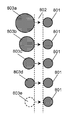
- FIG. 8 is a diagram for explaining recording marks recorded for detecting the influence of thermal interference.
- the recording compensation of the recording mark 801 that is the target of the recording compensation is executed for the recording condition of the recording mark 801 with respect to the front space 802. Therefore, the length of the recording mark 801 and the length of the front space 802 are constant.
- the front recording marks are recording marks 803a, 803b, 803c, 803d, and 803e having different lengths.
- the recording mark 803e indicates a state in which no front recording mark exists, and the recording mark 801 is an isolated mark. It is.
- the recording mark 801 is an isolated mark, it is assumed that the edge of the recording mark 801 is shifted due to the influence of thermal interference. If the state where the edge is shifted can be detected, the influence of optical interference can be removed and only the influence of thermal interference can be detected.
- the length of the space 802 in front of the recording mark 801 and the length of the space behind the recording mark 801 are such that the intersymbol interference of the recording mark ahead of each space does not affect. Is set. Further, it is more desirable to set the recording pattern of FIG. 5 in a range other than a part of the recording data of FIG.
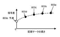
- FIG. 9 is a diagram showing a signal difference with respect to the front recording mark length.
- the horizontal axis represents the length of the front recording mark in FIG. 8, and the vertical axis represents the signal difference between the expected value signal and the reproduction signal for the recording mark 801.
- the length of the recording mark in the case of the front recording mark 803e is 0
- Signal difference that is, the signal difference when the horizontal axis is 0 can be predicted. If the change in the signal difference is small with respect to the length of the front recording mark, it means that there is little optical interference.
- the start edge of the recording mark 801 is changed so that the influence of thermal interference is eliminated. This is because the start edge of the recording mark 801 changes most due to the amount of heat of the front recording marks 803a, 803b, 803c, and 803d. Therefore, the recording compensation for changing the starting edge of the recording mark 801 is the most efficient. However, if the recording mark 801 is very small, the end edge also changes due to the change of the start edge, and therefore it is more desirable for the recording compensation to change the start edge and the end edge, respectively.
- the edges are adjusted so that the signal difference is minimized while changing the front recording marks 803a, 803b, 803c, 803d, and the recording marks 801, respectively.
- Optical interference is more affected when the length of the space between the front recording mark and the recording mark is short. Therefore, the most efficient recording compensation is to change the trailing edge of the front recording marks 803a, 803b, 803c, and 803d and the starting edge of the recording mark 801 at the same time so that the signal difference is minimized.
- the recording compensation for the recording marks 801 with respect to the front recording marks 803a, 803b, 803c, 803d and the front space 802 is performed. Furthermore, by applying the change amount of the recording condition changed by the recording compensation of the front recording marks 803a, 803b, 803c, and 803d to the recording mark 801 having the same length as the recording mark 801, the accuracy can be improved. Recording compensation allows recording conditions to be set.
- the interference such as intersymbol interference, optical interference, and thermal interference and perform recording compensation for the edge shift of the recording mark.
- the recording compensation of the recording mark 801 is performed on the front space 802.
- the recording compensation may be performed on the rear space by arranging a recording mark on the rear. Further, recording compensation may be performed for both the front space and the rear space.
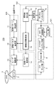
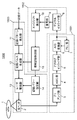
- FIG. 1 is a diagram showing an information recording / reproducing apparatus 100 according to the first embodiment.
- the information recording / reproducing apparatus 100 includes a reproducing unit 101, a recording compensation unit 102, and a recording unit 103.
- the reproduction unit 101 includes a preamplifier unit 3, an AGC unit 4, an analog equalizer unit 5, an A / D (Analog / Digital) conversion unit 6, and a PLL unit 7.
- the recording compensation unit 102 includes a digital equalizer unit 8, a decoding unit 9, a signal difference detection unit 10, and an information recording control unit 15.
- the recording unit 103 includes an optical head 2, a recording pattern generation unit 11, a recording pulse generation unit 12, a laser driving unit 13, and a recording power setting unit 14.
- the information recording / reproducing apparatus 100 records information on the information recording medium 1 and reproduces it.
- the information recording medium 1 is an information recording medium on which information is recorded and reproduced optically, for example, an optical disk.
- the optical head 2 converges laser light that has passed through an objective lens (not shown) on the recording layer of the information recording medium 1, receives the reflected light, and generates a reproduction signal indicating information recorded on the information recording medium 1.
- the numerical aperture NA of the objective lens is 0.84 to 0.86, more preferably 0.85.
- the wavelength of the laser light is 400 nm to 410 nm, and more preferably 405 nm.
- the preamplifier unit 3 amplifies the reproduction signal with a predetermined gain and outputs the amplified signal to the AGC unit 4.
- the AGC unit 4 amplifies the reproduction signal so that the level of the reproduction signal output from the A / D conversion unit 6 becomes a constant level using a preset target gain, and outputs the amplified signal to the analog equalizer unit 5 To do.
- the analog equalizer unit 5 has an LPF (Low-Pass Filter) characteristic that cuts off the high frequency range of the reproduction signal and a filter characteristic that amplifies a predetermined frequency band of the reproduction signal, and the reproduction waveform has a desired characteristic. Equalized and output to the A / D converter 6.
- LPF Low-Pass Filter
- the PLL unit 7 generates a reproduction clock synchronized with the reproduction signal after waveform equalization, and outputs it to the A / D conversion unit 6.
- the A / D conversion unit 6 samples the reproduction signal in synchronization with the reproduction clock output from the PLL unit 7, converts the analog signal into a digital signal, and outputs the analog signal to the PLL unit 7 and the digital equalizer unit 8.
- the digital equalizer section 8 reproduces the reproduction signal so that the frequency characteristic of the reproduction signal at the time of recording and reproduction becomes a preset frequency characteristic, for example, an MTF characteristic according to the recording density, a PR equalization characteristic, or the like. Adjust the frequency.
- the decoding unit 9 decodes the waveform equalized reproduction signal output from the digital equalizer unit 8 to generate a binarized signal.
- the decoding unit 9 performs, for example, decoding using a Viterbi algorithm, decoding using a BCJR (Bahl-Cocke-Jelinek-Raviv) algorithm, and the like.
- the signal difference detection unit 10 receives the waveform equalized reproduction signal output from the digital equalizer unit 8 and the binarized signal output from the decoding unit 9.
- the signal difference detection unit 10 generates an expected value signal from the binarized signal and the frequency characteristic targeted by the waveform equalization of the digital equalizer unit 8.
- the signal difference detection unit 10 detects a signal difference between the reproduction signal and the expected value signal.
- the information recording control unit 15 controls each unit in the information recording / reproducing apparatus such as the reproducing unit 101, the recording compensation unit 102, the recording unit 103, and a servo control unit (not shown) in order to adjust the recording pulse condition. Further, the information recording control unit 15 controls the selection of the recording pattern and the recording / reproducing operation when adjusting the recording pulse condition.
- the information recording control unit 15 records data including at least one recording mark or space having a recording density exceeding the optical resolution determined by the wavelength of the laser beam and the numerical aperture NA, which are optical conditions of the optical head 2. Is recorded on the information recording medium 1 to control the recording unit 103. For example, when the wavelength of the laser beam is 405 nm and the numerical aperture NA is 0.85, the length of the shortest mark or the shortest space is less than 119.1 nm.
- the information recording control unit 15 sets an optimum equalization characteristic corresponding to the set recording mark length, for example, a PR equalization characteristic, for the digital equalizer unit 8.
- the information recording control unit 15 receives the signal difference output from the signal difference detection unit 10.
- the information recording control unit 15 performs recording / reproducing operation of recording data on the information recording medium 1 under a plurality of recording conditions. Further, the information recording control unit 15 compares the signal difference measured for each recording condition with the target value stored in the information recording control unit 15 to determine the recording condition closest to the target value. .
- the target value is 0, for example.
- the information recording control unit 15 is, for example, an optical disk controller.
- the recording pattern generator 11 generates an NRZI signal that becomes a recording pattern from the input recording data.
- the recording pulse generator 12 generates a recording pulse train according to the NRZI signal based on the recording parameters changed by the information recording controller 15.
- the recording power setting unit 14 sets each recording power such as peak power Pp and bottom power Pb.
- the laser driving unit 13 controls the laser light emission operation of the optical head 2 according to the recording pulse train generated by the recording pulse generating unit 12 and the recording power set by the recording power setting unit 14.
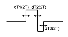
- FIG. 10A shows a recording pulse in which the recording mark in this embodiment performs recording compensation for 2T
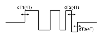
- FIG. 10B shows a recording pulse in which the recording mark in this embodiment performs recording compensation for 4T.
- dT1 (2T) is a parameter for changing the start edge of the recording mark
- dT2 (2T) and dT3 (2T) are parameters for changing the end edge of the recording mark.
- dT1 (4T) of the leading pulse is a parameter for changing the starting edge of the recording mark
- dT2 (4T) and dT3 (4T) of the last pulse are parameters for changing the trailing edge of the recording mark.
- FIG. 10B when changing the length of the recording mark with respect to the recording mark of 4T, the direction of changing dT1 (4T) and the direction of changing dT2 (4T) and dT3 (4T) are reversed. Set. Thereby, since the length of the recording pulse changes, the length of the recording mark to be recorded changes. Since the recording pulse of FIG. 10B is set by the recording pulse of dT1 (4T) and the recording pulse of dT2 (4T), dT1 (4T), dT2 (4T) and dT3 (4T) are set. And may be changed individually. In addition, when changing the phase of the recording mark with respect to the 4T recording mark in FIG.
- FIG. 10B the direction in which dT1 (4T) is changed and the direction in which dT2 (4T) and dT3 (4T) are changed are the same direction.
- FIG. 10B only sets the recording pulse of the first pulse and the last pulse, so the entire recording pulse including the intermediate pulse cannot be changed in the same direction, but the start edge of the recording mark to be recorded Since the end edges are changed in the same direction, the phase changes. If it is possible to set all the recording pulses as hardware of the information recording / reproducing apparatus 100, it is more desirable to change all the recording pulses in FIG. 10B in the same direction.
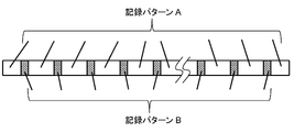
- FIG. 11 is a diagram showing an example of recording data used for recording compensation in the first embodiment.
- FIG. 11 includes a recording pattern A and a recording pattern B.
- the recording pattern A is set as a recording pattern that facilitates PLL control and DC control.
- the recording pattern A is, for example, a single signal or special recording data with a limited appearance length, such as a random signal composed of 5T to 8T.
- the recording pattern A may be a different recording pattern each time.
- Recording pattern B is set as a special recording pattern for recording compensation. Therefore, the recording pattern B is not continuously arranged so that PLL control, DC control, and the like do not become unstable, but the recording pattern A and the recording pattern B are alternately set as shown in FIG. Is desirable. In addition, the same recording pattern is set for each recording pattern B. When recording compensation is performed for a plurality of recording marks simultaneously, the recording pattern B may be a different recording pattern each time.
- FIGS. 12A and 12B show binary signals of the NRZI signal of the recording pattern B, and the recording mark for recording compensation is 2T.
- FIG. 12A is a diagram showing a binary signal when the 2T recording mark is an isolated mark.
- the recording pattern of FIG. 12A is used when recording compensation is executed for the recording condition of 2T recording marks. If the recording pattern of FIG. 12A is recorded, the recording mark described in FIG. 5 can be formed.
- a space having a space length LS is set before and after the 2T recording mark.
- the space length LS is a length that the 2T mark does not affect the intersymbol interference of the preceding and following recording marks.
- the space length LS as the recording pattern is calculated from the physical length per 1T set by the recording density. For example, if the recording density is set so that the physical length per 1T is 24 nm, the space length LS as the recording pattern is 50T. In this way, the space length LS in the recording pattern can be determined.
- the space length LS in the recording pattern may be obtained from a reproduction signal obtained by actually recording and reproducing the recording data.
- the space length LS in the recording pattern is set to such a length that the reproduction signals in the front space 503 and the rear space 504 have a constant signal level in FIG.
- FIG. 12B is a diagram illustrating a binary signal when a 4T recording mark is arranged in front of a 2T recording mark.
- the space in front of the 2T recording mark is 2T.
- the recording pattern in FIG. 12B is used when recording compensation is performed for the recording condition of a 2T recording mark having a 2T space in front. If the length 4T of the recording mark in front of the 2T recording mark in FIG. 12B is changed, the recording mark described in FIG. 8 can be formed.
- a space having a space length LS is set in front of the 4T recording mark and behind the 2T recording mark, as in FIG. 12A.
- the lengths of the front and rear space lengths LS may be different as long as there is no intersymbol interference.
- the binary signal of the start position and the end position in the recording pattern B in FIGS. 12A and 12B may be determined by the connection relationship with the recording pattern A. For example, if the start position and end position of the recording pattern B are 3T recording marks as shown in FIGS. 12A and 12B and the start position and end position of the recording pattern A are set as spaces, the recording pattern A and the recording pattern At the boundary of B, the recording mark is 3T.
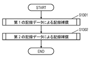
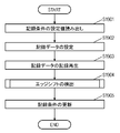
- FIG. 13 is a flowchart for executing recording compensation in the first embodiment.
- the first recording compensation is executed using the first recording data (S1301), and then the second recording compensation is executed using the second recording data (S1302).
- S1301 the first recording data
- S1302 the second recording compensation
- the recording mark for executing the recording compensation is an isolated mark, and the length of the space before and after the recording mark is set to a length that does not cause intersymbol interference. Recorded data.
- the second recording data includes a second recording mark arranged in front of or behind the first recording mark for executing the recording compensation, and the first recording mark and the second recording mark.
- This is recording data that changes the length of the second recording mark while keeping the length of the space between them constant.
- the length of the space adjacent to the first recording mark on the side opposite to the second recording mark, and adjacent to the second recording mark on the side opposite to the first recording mark. The length of the space to be set is set so as not to cause intersymbol interference.
- the recording compensation of the recording pulse condition of each recording mark is performed without being affected by other recording marks. Then, by executing the processing of S1302 after the processing of S1301, even if the first recording mark and the second recording mark interfere with each other, the recording compensation of the recording pulse of each recording mark has already been performed. .
- the recording compensation of the recording pulse condition of the first recording mark can be performed against the influence of the thermal interference generated by the second recording mark.
- the recording pulse condition of the recording mark is also determined for the length of the short space included in the modulation code when information is actually recorded. That is, in the case where the recording data is in FIG. 12B, the recording pulse condition of the 2T recording mark having a 2T space ahead is determined.
- the recording pulse condition is similarly determined for a recording mark other than the 2T recording mark or a combination of spaces other than the 2T space.
- the recording pulse conditions of the first recording mark and the second recording mark are further changed. It is desirable to select a recording condition in which the signal difference is closest to the index target value. Thereby, the influence by optical interference can be reduced.
- the recording compensation for the edge shift of the recording mark can be performed.
- recording with a reduced error rate of recorded information can be realized under appropriate recording conditions, and a more stable high-density recording / reproducing system can be realized.
- FIG. 14 is a flowchart for performing recording compensation in each step of FIG. This recording compensation is performed on the information recording medium 1 by the information recording / reproducing apparatus 100.
- the setting value of the recording condition is read.
- the information recording / reproducing apparatus 100 reads information on the recording power and recording pulse conditions stored in the information recording medium 1 or the information recording / reproducing apparatus 100, for example, in a memory, as a recording parameter of the initial recording conditions.
- the information stored in the information recording medium 1 is a value in which a recording condition is designated in advance based on a result of evaluation of the recording characteristics of the information recording medium 1 by the manufacturer when the information recording medium 1 is manufactured. It is. Further, as information stored in the information recording medium 1, the information recording / reproducing apparatus 100 for the information recording medium 1 records a recording condition in the past in an area for recording information unique to the apparatus. There is. Further, the information recorded in the information recording / reproducing apparatus 100 is a value for which a recording condition is designated in advance based on a result of the manufacturer evaluating the recording characteristics of the apparatus at the time of manufacturing the apparatus.
- the recording power and the recording pulse condition are the set values related to the recording power and the recording pulse described in FIG.
- the information recording control unit 15 generates a recording condition setting table used when recording predetermined recording data under a plurality of recording conditions.
- the recording condition setting table is a table for changing recording parameters. For example, when adjusting the length of the 2T recording mark, the information recording control unit 15 sets the recording parameter dT1 (2T) of the start edge to the range from ⁇ 4 step to +4 step and the recording parameter dT2 of the end edge according to the recording condition table. (2T) and dT3 (2T) are offset-changed in a range from +4 step to ⁇ 4 step at intervals of 1 step.
- the information recording control unit 15 sets the recording parameters dT1 (2T), dT2 (2T), and dT3 (2T) of the starting edge and the ending edge according to the recording condition table.
- the offset of the range from 8step to + 8step is changed at intervals of 2step.
- the start edge or the end edge may be individually changed.
- 1 step is, for example, a unit obtained by dividing the recording clock period T by 32.
- 1 step is about 237 ps.
- 1step may be set as a fixed value, for example, 250 ps.
- the information recording control unit 15 designates recording data to be recorded on the information recording medium 1 to the recording pattern generation unit 11. Note that the recording data may be generated for each recording operation. In order to shorten the generation time of the recording data, it is more preferable that the recording data generated in advance is stored in the information recording / reproducing apparatus 100.
- the recording data is the recording data described with reference to FIG.
- the recording pattern generator 11 generates an NRZI signal based on the designated recording data.
- the recording pulse generation unit 12 generates a recording pulse train of a laser emission waveform based on the recording pulse shape of the recording parameter output from the information recording control unit 15 and the NRZI signal output from the recording pattern generation unit 11.
- the recording power setting unit 14 sets each recording power such as the peak power Pp and the bottom power Pb according to the initial recording condition of the information recording control unit 15.
- the information recording control unit 15 moves the optical head 2 to a recording area for adjusting a recording parameter.
- the recording area is, for example, a recording area for adjusting recording power and recording pulse provided on the innermost circumference of the information recording medium 1, and is called a PCA (Power Calibration Area) area in the DVD.
- PCA Power Calibration Area
- the laser driving unit 13 controls the laser light emission operation of the optical head 2 according to the recording pulse train generated by the recording pulse generating unit 12 and the recording power set by the recording power setting unit 14, and the information recording medium Recording data is recorded on a track in a recording area (not shown) with a predetermined recording length, for example, a length in a minimum recording unit, an address unit, and the like.
- the information recording control unit 15 refers to the recording condition table generated in S1402 and controls the laser driving unit 13 to change the recording condition and record the recording data.
- the information recording / reproducing apparatus 100 reproduces a track in which recording data is recorded under a plurality of recording conditions.
- the optical head 2 generates a reproduction signal indicating information read from the information recording medium 1.
- the reproduction signal is amplified by the preamplifier unit 3 and AC coupled, and then input to the AGC unit 4.
- the gain is adjusted so that the output of the subsequent analog equalizer unit 5 has a constant amplitude.
- the reproduction signal output from the AGC unit 4 is waveform-equalized by the analog equalizer unit 5.
- the waveform-equalized reproduction signal is output to the A / D converter 6.
- the A / D converter 6 samples the reproduction signal in synchronization with the reproduction clock output from the PLL unit 7.
- the PLL unit 7 extracts a reproduction clock from the reproduction signal sampled by the A / D conversion unit 6.
- the reproduction signal generated by the sampling of the A / D conversion unit 6 is input to the digital equalizer unit 8.
- the digital equalizer unit 8 equalizes the waveform of the reproduction signal.
- the decoding unit 9 decodes the waveform equalized reproduction signal output from the digital equalizer unit 8 to generate a binarized signal.
- the signal difference detection unit 10 receives the waveform equalized reproduction signal output from the digital equalizer unit 8 and the binarized signal output from the decoding unit 9.
- the signal difference detection unit 10 obtains a signal difference between the reproduction signal and the expected value signal.
- the signal difference is output to the information recording control unit 15.
- the information recording control unit 15 compares the signal difference for the plurality of recording conditions detected in S1404 with the index target value stored in the information recording control unit 15, and determines the recording condition closest to the index target value. select.
- the code interference is removed and an edge shift that can directly determine the optimum recording condition is detected.
- Detecting an edge shift requires a binary signal that is recording data, a reproduction signal when the binary signal is recorded and reproduced, and an expected value signal.
- the expected value signal is a convolution of a binary signal and an isolated waveform, as in the first embodiment.
- the notation of each signal is a binary signal b (t), a reproduction signal r (t), an expected value signal e (t), an isolated waveform f (t), and a correction signal rr (t).
- the detection pattern is a combination of the preceding space and the recording mark that is the self mark.
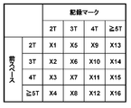
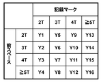
- the length of the previous space is “2T”, “3T”, “4T”, “5T or more”
- the length of the own mark is “2T”, “3T”, “4T” ”,“ 5T or more ”, and 16 combinations. Since there are two types of edges, the start edge and the end edge, respectively, the total number of detection patterns is 32.
- the detection pattern of the second embodiment is not limited to the combination of the previous space and the self mark.
- the detection pattern may be a combination of a self mark and a rear space.
- the detection pattern may be a combination of the front space, the self mark, and the rear space.
- the detection pattern may be a combination of the previous mark, the previous space, and the self mark.
- the length of the front space or the self mark is not limited to four types of “2T”, “3T”, “4T”, and “5T or more”. Further, the length of the front space and the self mark may be different.
- the length of the front space is “2T”, “3T”, “4T”, “5T”, “6T or more”, and the length of the own mark is “2T”, “3T”, “ It is possible to use 7 types of “4T”, “5T”, “6T”, “7T”, and “8T”.
- the signal difference between the reproduced signal r (t) at the edge portion and the expected value signal e (t) with respect to the detection pattern is totaled to detect an average signal difference.
- the signal difference can be averaged to suppress variation in detection.
- the signal difference is detected for all detection patterns.
- FIG. 16A shows the edge shift X of the starting edge in the detection pattern.
- FIG. 16B shows the edge shift X of the terminal edge in the detection pattern.
- the total number of detection patterns is 32, and edge shifts X1 to X16 of the start edge in the detection pattern and edge shifts X17 to X32 of the end edge in the detection pattern are detected.
- FIG. 17A shows the signal difference Y at the start edge in the detection pattern.
- FIG. 17B shows the signal difference Y at the end edge in the detection pattern. Since the total number of detection patterns is 32, signal differences Y1 to Y16 at the start edge in the detection pattern and signal differences Y17 to Y32 at the end edge in the detection pattern are detected.
- (Expression 1) is expressed by an edge shift X matrix, a signal difference Y matrix, and a conversion coefficient A matrix.
- the matrix of transform coefficients A expresses the degree of influence that each edge shift interferes with other edges. Therefore, the matrix of the conversion coefficient A is a square matrix with respect to the total number of combinations of detection patterns.
- the signal difference can be obtained from the reproduction signal and the expected value signal. Therefore, if a matrix of conversion coefficients A can be obtained, an edge shift X matrix can be obtained.
- a method for obtaining the matrix of the conversion coefficient A will be described.
- a binary signal corresponding to an edge portion for one detection pattern is intentionally changed by a predetermined amount ⁇ T. That is, the edge shift X changes by ⁇ T.
- the predetermined amount ⁇ T is, for example, 0.2T, but may be a longer change amount or a shorter change amount.
- the change amount ⁇ f (t) of the isolated waveform with respect to the change of the predetermined amount ⁇ T is calculated.
- the change amount ⁇ f (t) of the isolated waveform is calculated by f (t) ⁇ ⁇ T.
- the change amount ⁇ f (t) of the isolated waveform is added to the detection pattern in the reproduction signal r (t), and the signal difference YY is detected again from the added signal and the expected value signal. From the difference between the signal difference YY and the signal difference Y and a predetermined amount ⁇ T, the conversion coefficient A related to the edge portion for one detection pattern can be obtained. The conversion coefficient A related to other detection patterns can be obtained in the same manner.
- a matrix of the conversion coefficient A related to the edge shift X1 can be obtained. That is, by dividing the difference between the signal difference Y matrix and the signal difference YY matrix by a predetermined amount ⁇ T, a matrix of the conversion coefficient A related to the edge shift X1 can be obtained.
- Matrix elements of the conversion coefficient A relating to the edge shift X1 are A (1,1) to A (1,32) shown in (Equation 3).
- the matrix elements of the conversion coefficient A related to the edge shifts X2 to X32 can be obtained. As described above, all matrix elements of the conversion coefficient A can be obtained.
- the matrix of the edge shift X can be obtained from the inverse matrix of the conversion coefficient A in (Equation 1).
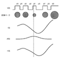
- FIG. 18 is a diagram for explaining the addition of the variation ⁇ f (t) of the isolated waveform at the specific edge portion in the reproduction signal r (t).
- the recording signal when the binary signal b (t) of the NRZI signal, which is a recording signal, and the binary signal b (t) are recorded on the information recording medium 1, and the reproduction signal reproducing the recording mark.
- reproduction signal r (t), the change amount ⁇ f (t) of the isolated waveform, and the correction signal rr (t) are assumed to change upward due to the recording mark.
- a broken line indicates a specific edge portion to be detected by the recording mark, and the front space is 3T and the recording mark is the starting edge of 2T.
- the start edge of a 2T recording mark whose front space is 3T changes by a predetermined amount ⁇ T in the direction in which the recording mark becomes larger.
- the change amount ⁇ f (t) of the isolated waveform in FIG. 18 is calculated as f (t) ⁇ ⁇ T.
- the isolated waveform change amount ⁇ f (t) is an estimated amount by which the reproduction signal r (t) changes when the start edge is changed by ⁇ T.
- the matrix element of the conversion coefficient A can be obtained for a detection pattern other than the start edge of a 2T recording mark whose front space is 3T.
- the change amount ⁇ f (t) of the isolated waveform was calculated as f (t) ⁇ ⁇ T. This obtains the variation ⁇ f (t) of the isolated waveform with respect to the center of 1T.
- the edge of the recording mark is changed, the starting point of the recording mark changes. Therefore, it is more desirable to perform the calculation by changing the phase of the change amount ⁇ f (t) of the isolated waveform by ⁇ T corresponding to the change ⁇ T of the edge of the recording mark.
- the correction signal rr (t) can be obtained with higher accuracy.
- correction signal rr (t) may be a reproduction signal that is actually recorded and reproduced by changing the recording pulse condition by ⁇ T instead of the calculation based on the change amount ⁇ f (t) of the isolated waveform.
- FIG. 15 is a diagram showing an information recording / reproducing apparatus 1500 according to the second embodiment.
- the information recording / reproducing apparatus 1500 includes a reproducing unit 1501, a recording compensation unit 1502, and a recording unit 1503.
- the reproduction unit 1501 includes a preamplifier unit 3, an AGC unit 4, an analog equalizer unit 5, an A / D conversion unit 6, and a PLL unit 7.
- the recording compensation unit 1502 includes a digital equalizer unit 8, a decoding unit 9, an edge shift detection unit 16, and an information recording control unit 15.
- the recording unit 1503 includes an optical head 2, a recording pattern generation unit 11, a recording pulse generation unit 12, a laser driving unit 13, and a recording power setting unit 14.
- the playback unit 1501 is the same as the playback unit 101 of the information recording / playback apparatus 100. Further, in the recording compensation unit 1502, the signal difference detection unit 10 is changed to the edge shift detection unit 16 with respect to the recording compensation unit 102 of the information recording / reproducing apparatus 100.
- the recording unit 1503 is the same as the recording unit 103 of the information recording / reproducing apparatus 100. Therefore, in Embodiment 2, the edge shift detection unit 16 will be described.
- FIG. 19 is a flowchart for performing recording compensation of recording pulse conditions in the information recording / reproducing apparatus 1500.
- S1901 First, the setting value of the recording condition is read. S1901 is the same as S1401 of FIG. 14 in the first embodiment.
- S1902 Next, recording data for recording compensation is set.
- S1902 is the same as S1403 of FIG. 14 in the first embodiment. However, the recording data to be used is different.
- recording compensation is executed using different recording data.
- the recording compensation is for directly obtaining the optimum recording condition by using one recording data. Therefore, the recording compensation in the second embodiment needs to use recording data including all detection patterns.
- the recording data in the second embodiment is a random signal including all detection patterns. Further, in order to eliminate the unevenness in the number of appearances of the detection patterns, it is more desirable that the recorded data has substantially the same number of appearances of the detection patterns.
- recording data corresponding to the detection pattern may be used, and a plurality of recording data corresponding to the detection pattern change may be used.
- the recording / reproducing operation of the recording data is executed on the information recording medium 1.
- the information recording control unit 15 moves the optical head 2 to a recording area for adjusting a recording parameter.
- the laser driving unit 13 controls the laser light emission operation of the optical head 2 according to the recording pulse train generated by the recording pulse generating unit 12 and the recording power set by the recording power setting unit 14, thereby displaying the information recording medium 1.
- Recording data is recorded on a track in a recording area not to be recorded with a predetermined recording length, for example, a length in a minimum recording unit, an address unit, or the like.
- the information recording / reproducing apparatus 1500 reproduces the track on which the recording data is recorded.
- the optical head 2 generates a reproduction signal indicating information read from the information recording medium 1.
- the playback unit 1501 outputs a playback signal as a playback signal.
- the recording compensation unit 1502 receives a reproduction signal.
- the digital equalizer unit 8 equalizes the waveform of the reproduction signal.
- the decoding unit 9 decodes the waveform-equalized reproduction signal output from the digital equalizer unit 8 to generate a binarized signal.
- the edge shift detection unit 16 receives the waveform-equalized reproduction signal output from the digital equalizer unit 8 and the binarized signal output from the decoding unit 9.
- the edge shift detection unit 16 detects an edge shift, which is an edge shift, from the reproduction signal and the binarized signal, and outputs the detected edge shift to the information recording control unit 15. Details of the operation of the edge shift detector 16 will be described later.
- the recording condition is updated.
- the information recording control unit 15 updates the recording conditions based on the edge shift output from the edge shift detection unit 16.
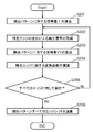
- FIG. 20 is a flowchart of the operation of the edge shift detection unit 16.
- the edge shift detection unit 16 receives the waveform-equalized reproduction signal output from the digital equalizer unit 8 and the binarized signal output from the decoding unit 9.
- the edge shift detection unit 16 generates an expected value signal from the binarized signal and the frequency characteristic targeted by the waveform equalization of the digital equalizer unit 8.
- the edge shift detection unit 16 detects a signal difference between the reproduction signal and the expected value signal.
- the signal difference Y in the second embodiment is the difference between the reproduction signal and the expected value signal at the edge portion of the recording mark.
- the edge shift detection unit 16 calculates a signal difference for each detection pattern. At this time, since a matrix operation is required in the arithmetic processing described later, the signal difference Y calculated for each detection pattern is represented by a matrix. Thereby, a matrix corresponding to the left side in (Equation 1) is obtained. Note that the reproduction signal in S2001 is the first reproduction signal. The matrix obtained in S2001 is the first matrix.
- a reproduction signal is acquired by changing a specific edge.
- the edge shift detection unit 16 obtains a reproduction signal when the edge for one detection pattern is changed by a predetermined amount.
- the reproduction signal in S2002 can be obtained by adding the change amount of the isolated waveform to the first reproduction signal.
- the position where the change amount of the isolated waveform is added to the first reproduction signal is the edge portion changed by a predetermined amount.
- the isolated waveform is a response characteristic per 1T and is equal to the frequency characteristic targeted by the waveform equalization of the digital equalizer unit 8.
- the reproduction signal in S2002 may be a reproduction signal that is actually reproduced by executing the recording / reproduction of S1903 in FIG. 19 by changing the recording pulse condition by a predetermined amount.
- the reproduction signal in S2002 is a second reproduction signal.
- a signal difference YY with respect to the detection pattern is calculated.
- the edge shift detection unit 16 detects a signal difference YY between the second reproduction signal obtained in S2002 and the expected value signal.
- the edge shift detection unit 16 calculates a signal difference for each detection pattern.
- the signal difference YY calculated for each detection pattern is represented by a matrix.
- a matrix corresponding to the left side in (Expression 2) is obtained. Note that the matrix obtained in S2003 is the second matrix.
- the edge shift detection unit 16 calculates a conversion coefficient related to the specific edge changed in S2002 from the first matrix obtained in S2001, the second matrix obtained in S2003, and the predetermined change amount in S2002.
- the edge shift detection unit 16 calculates the matrix element of the transform coefficient using (Equation 3). That is, the matrix of transform coefficients for a specific edge is calculated by dividing the difference between the first matrix and the second matrix by a predetermined amount. In (Equation 3), matrix elements A (1, 1) to A (1, 32) are obtained. Thereby, the conversion coefficient regarding a specific edge can be obtained.
- S2002 to S2004 may be a flowchart for sequentially executing all the edges of the detection pattern.
- the edge shift of all detection patterns is calculated.
- the edge shift detection unit 16 calculates the edge shift edge shift of all the detection patterns using the first matrix obtained in S2001 and the matrix of transform coefficients obtained in S2002 to S2005.
- the edge shift can be calculated from the first matrix and the inverse matrix of the transform coefficient, as shown in (Equation 1).
- the edge shift detection unit 16 can detect an edge shift which is an edge shift.
- the interference relationship of the edge shift can be estimated, and finally each detection Edge shift detection for the pattern can be performed. That is, the recording compensation for the edge shift of the recording mark can be performed. As a result, recording marks without edge shift can be formed, and recording with few errors can be performed as a whole reproduction signal.
- the information recording / reproducing apparatus 1500 including the reproducing unit 1501 and the recording unit 1503 has been described.
- a configuration having only the recording compensation unit 1502 may be used.
- the recording compensation unit 1502 is applied as an edge shift detection device that detects an edge shift from a digitized reproduction signal, and can be used as an apparatus for evaluating the edge shift of the reproduction signal.
- the lengths of recording marks and spaces of 5T or more are combined into one, but they may be set respectively for recording marks and spaces from 5T to the longest mark.
- the numerical values such as the wavelength of the laser beam and the numerical aperture NA of the objective lens are not limited to the above.
- the processing procedure in the present embodiment may have any procedure as long as the above steps can be executed.
- the present disclosure may be a recording / reproducing program for executing the functions of the information recording / reproducing apparatus according to the embodiment.
- the recording / reproducing program may be stored in a memory inside the information recording / reproducing apparatus in the present embodiment.
- the recording / reproducing program may be stored in a memory inside the information recording / reproducing apparatus after the information recording / reproducing apparatus is shipped.
- the memory in the information recording / reproducing apparatus may be accessed via the Internet, and the recording / reproducing program may be stored in the memory in the information recording / reproducing apparatus.
- the information recording / reproducing apparatus may reproduce the information recording medium on which the information of the recording / reproducing program is recorded, and the recording / reproducing program may be stored in a memory inside the information recording / reproducing apparatus.
- the present disclosure can be applied to an information recording / reproducing apparatus for recording / reproducing information with respect to various information recording media for recording data signals by laser light, electromagnetic force, or the like.
- the present invention can be applied to a recorder using an optical disk device, a data archiver device, and the like.
Landscapes
- Engineering & Computer Science (AREA)
- Signal Processing (AREA)
- Optical Recording Or Reproduction (AREA)
- Optical Head (AREA)
Abstract
La présente invention concerne un dispositif de lecture et d'enregistrement d'informations qui comprend : une unité de lecture qui génère un signal numérique à partir d'un signal analogique qui a été enregistré sur un support d'enregistrement d'informations ; une unité de compensation d'enregistrement qui génère un signal de valeur attendue à partir du signal numérique, détecte la différence entre le signal numérique et le signal de valeur attendue, et ajuste les conditions d'enregistrement pour enregistrer des informations sur le support d'enregistrement d'informations ; et une unité d'enregistrement qui enregistre des informations sur la base des conditions d'enregistrement. Le dispositif de lecture et d'enregistrement d'informations effectue une première compensation d'enregistrement qui ajuste les conditions d'enregistrement à l'aide de premières données d'enregistrement d'une certaine longueur, les longueurs des espaces avant et après des premières marques d'enregistrement et les longueurs des espaces avant et après des secondes marques d'enregistrement ne provoquant pas d'interférence inter-symboles ; place les secondes marques d'enregistrement, sur lesquelles a été effectuée la première compensation d'enregistrement, soit avant, soit après les premières marques d'enregistrement sur lesquelles a été effectuée la première compensation d'enregistrement ; garde constantes les longueurs des espaces qui sont pris en sandwich entre les premières marques d'enregistrement et les secondes marques d'enregistrement ; et, à l'aide de secondes données d'enregistrement qui changent les longueurs des secondes marques d'enregistrement, effectue une seconde compensation d'enregistrement qui ajuste les conditions d'enregistrement pour les premières marques d'enregistrement.
Priority Applications (2)
| Application Number | Priority Date | Filing Date | Title |
|---|---|---|---|
| JP2015557583A JPWO2015107572A1 (ja) | 2014-01-17 | 2014-09-04 | 情報記録再生装置、及び情報記録再生方法 |
| US15/166,112 US9570102B2 (en) | 2014-01-17 | 2016-05-26 | Information recording and reproducing apparatus and information recording and reproducing method |
Applications Claiming Priority (2)
| Application Number | Priority Date | Filing Date | Title |
|---|---|---|---|
| JP2014006554 | 2014-01-17 | ||
| JP2014-006554 | 2014-01-17 |
Related Child Applications (1)
| Application Number | Title | Priority Date | Filing Date |
|---|---|---|---|
| US15/166,112 Continuation US9570102B2 (en) | 2014-01-17 | 2016-05-26 | Information recording and reproducing apparatus and information recording and reproducing method |
Publications (1)
| Publication Number | Publication Date |
|---|---|
| WO2015107572A1 true WO2015107572A1 (fr) | 2015-07-23 |
Family
ID=53542501
Family Applications (1)
| Application Number | Title | Priority Date | Filing Date |
|---|---|---|---|
| PCT/JP2014/004543 Ceased WO2015107572A1 (fr) | 2014-01-17 | 2014-09-04 | Dispositif de lecture et d'enregistrement d'informations, et procédé de lecture et d'enregistrement d'informations |
Country Status (3)
| Country | Link |
|---|---|
| US (1) | US9570102B2 (fr) |
| JP (1) | JPWO2015107572A1 (fr) |
| WO (1) | WO2015107572A1 (fr) |
Cited By (2)
| Publication number | Priority date | Publication date | Assignee | Title |
|---|---|---|---|---|
| JP2019160370A (ja) * | 2018-03-14 | 2019-09-19 | パナソニックIpマネジメント株式会社 | 情報記録再生装置及び情報記録再生方法 |
| WO2020100777A1 (fr) * | 2018-11-15 | 2020-05-22 | パナソニックIpマネジメント株式会社 | Dispositif de disque optique |
Families Citing this family (1)
| Publication number | Priority date | Publication date | Assignee | Title |
|---|---|---|---|---|
| WO2017126330A1 (fr) * | 2016-01-21 | 2017-07-27 | ソニー株式会社 | Dispositif de réglage d'enregistrement, procédé de réglage d'enregistrement, et programme |
Citations (5)
| Publication number | Priority date | Publication date | Assignee | Title |
|---|---|---|---|---|
| JP2000231719A (ja) * | 1998-09-14 | 2000-08-22 | Matsushita Electric Ind Co Ltd | 光学情報の記録再生装置および情報記録媒体 |
| JP2007213731A (ja) * | 2006-02-10 | 2007-08-23 | Samsung Electronics Co Ltd | 光情報記録装置および光情報記録方法 |
| JP2008112509A (ja) * | 2006-10-31 | 2008-05-15 | Sanyo Electric Co Ltd | 光ディスク記録装置 |
| JP2010003328A (ja) * | 2008-06-18 | 2010-01-07 | Hitachi Ltd | 光学的情報記録方法、光学的情報再生方法、および光ディスク装置 |
| JP2011081901A (ja) * | 2008-10-09 | 2011-04-21 | Panasonic Corp | 光記録方法、光記録装置、原盤露光装置、光学的情報記録媒体および再生方法 |
Family Cites Families (5)
| Publication number | Priority date | Publication date | Assignee | Title |
|---|---|---|---|---|
| JP2005092942A (ja) * | 2003-09-16 | 2005-04-07 | Hitachi Ltd | 光ディスク記録方法、光ディスク装置、及び光ディスク |
| JP4049147B2 (ja) * | 2004-11-05 | 2008-02-20 | 船井電機株式会社 | 光ディスク装置 |
| US20070008850A1 (en) | 2005-07-06 | 2007-01-11 | Yukihisa Nakajo | Apparatus and method of optically recording data |
| JP4274183B2 (ja) * | 2005-11-24 | 2009-06-03 | ソニー株式会社 | 記録再生装置、レーザ駆動パルス調整方法 |
| JP5469390B2 (ja) | 2009-07-15 | 2014-04-16 | 日立コンシューマエレクトロニクス株式会社 | 再生信号評価方法及び記録調整方法 |
-
2014
- 2014-09-04 WO PCT/JP2014/004543 patent/WO2015107572A1/fr not_active Ceased
- 2014-09-04 JP JP2015557583A patent/JPWO2015107572A1/ja active Pending
-
2016
- 2016-05-26 US US15/166,112 patent/US9570102B2/en not_active Expired - Fee Related
Patent Citations (5)
| Publication number | Priority date | Publication date | Assignee | Title |
|---|---|---|---|---|
| JP2000231719A (ja) * | 1998-09-14 | 2000-08-22 | Matsushita Electric Ind Co Ltd | 光学情報の記録再生装置および情報記録媒体 |
| JP2007213731A (ja) * | 2006-02-10 | 2007-08-23 | Samsung Electronics Co Ltd | 光情報記録装置および光情報記録方法 |
| JP2008112509A (ja) * | 2006-10-31 | 2008-05-15 | Sanyo Electric Co Ltd | 光ディスク記録装置 |
| JP2010003328A (ja) * | 2008-06-18 | 2010-01-07 | Hitachi Ltd | 光学的情報記録方法、光学的情報再生方法、および光ディスク装置 |
| JP2011081901A (ja) * | 2008-10-09 | 2011-04-21 | Panasonic Corp | 光記録方法、光記録装置、原盤露光装置、光学的情報記録媒体および再生方法 |
Cited By (5)
| Publication number | Priority date | Publication date | Assignee | Title |
|---|---|---|---|---|
| JP2019160370A (ja) * | 2018-03-14 | 2019-09-19 | パナソニックIpマネジメント株式会社 | 情報記録再生装置及び情報記録再生方法 |
| WO2020100777A1 (fr) * | 2018-11-15 | 2020-05-22 | パナソニックIpマネジメント株式会社 | Dispositif de disque optique |
| JPWO2020100777A1 (ja) * | 2018-11-15 | 2021-10-14 | パナソニックIpマネジメント株式会社 | 光ディスク装置 |
| US11295779B2 (en) | 2018-11-15 | 2022-04-05 | Panasonic Intellectual Property Management Co., Ltd. | Optical disk device |
| JP7316587B2 (ja) | 2018-11-15 | 2023-07-28 | パナソニックIpマネジメント株式会社 | 光ディスク装置 |
Also Published As
| Publication number | Publication date |
|---|---|
| US20160275981A1 (en) | 2016-09-22 |
| US9570102B2 (en) | 2017-02-14 |
| JPWO2015107572A1 (ja) | 2017-03-23 |
Similar Documents
| Publication | Publication Date | Title |
|---|---|---|
| US8743671B2 (en) | Method for adjusting recording condition, optical disc device, and information recording method | |
| WO2015107572A1 (fr) | Dispositif de lecture et d'enregistrement d'informations, et procédé de lecture et d'enregistrement d'informations | |
| TW201732787A (zh) | 記錄調整裝置、記錄調整方法、及程式 | |
| JP4597911B2 (ja) | 光記録再生方法および装置および信号処理回路および光記録再生プログラムおよび情報記録媒体 | |
| JP4395455B2 (ja) | 光情報記録装置および方法および信号処理回路 | |
| WO2006112277A1 (fr) | Procede d’optimisation du mode d’impulsions d’enregistrement dans l’enregistrement de donnees sur support d’enregistrement d’informations | |
| JP7442100B2 (ja) | 記録状態評価方法、記録補償方法及び情報記録再生装置 | |
| JP5607148B2 (ja) | 情報再生方法、情報記録方法および情報記録媒体 | |
| JP2008112509A (ja) | 光ディスク記録装置 | |
| JP4988901B2 (ja) | 記録条件の調整方法、光ディスク装置及び情報記録方法 | |
| JPWO2010092821A1 (ja) | 情報記録再生装置および情報記録再生方法 | |
| JP2019160370A (ja) | 情報記録再生装置及び情報記録再生方法 | |
| JP2009266277A (ja) | 情報記録装置及び記録条件調整方法 | |
| JP4911224B2 (ja) | 光学的情報記録媒体への信号記録条件調整方法、情報記録再生装置 | |
| US20080151716A1 (en) | Optical disc recording and reproducing apparatus and optical disc recording and reproducing method | |
| JP4868172B2 (ja) | 光学的情報記録再生装置、および光学的情報記録再生装置の記録ストラテジ調整方法 | |
| JP5309197B2 (ja) | 記録条件の調整方法及び光ディスク装置 | |
| JP5427903B2 (ja) | 記録条件の調整方法及び光ディスク装置 | |
| JP2007280492A (ja) | 記録再生装置、記録再生方法、記録再生プログラム、記録信号調整装置、記録信号調整方法及び記録信号調整プログラム | |
| JP2009116977A (ja) | 光ディスク記録再生装置及び光ディスク記録再生方法 | |
| WO2014054275A1 (fr) | Support d'enregistrement d'informations optiques et dispositif d'enregistrement d'informations optiques | |
| JP2009140566A (ja) | 記録ストラテジ調整方法、および情報記録再生装置 |
Legal Events
| Date | Code | Title | Description |
|---|---|---|---|
| 121 | Ep: the epo has been informed by wipo that ep was designated in this application |
Ref document number: 14878527 Country of ref document: EP Kind code of ref document: A1 |
|
| ENP | Entry into the national phase |
Ref document number: 2015557583 Country of ref document: JP Kind code of ref document: A |
|
| NENP | Non-entry into the national phase |
Ref country code: DE |
|
| 122 | Ep: pct application non-entry in european phase |
Ref document number: 14878527 Country of ref document: EP Kind code of ref document: A1 |