WO2015107687A1 - 電源制御システム、電源制御装置及び方法 - Google Patents
電源制御システム、電源制御装置及び方法 Download PDFInfo
- Publication number
- WO2015107687A1 WO2015107687A1 PCT/JP2014/050919 JP2014050919W WO2015107687A1 WO 2015107687 A1 WO2015107687 A1 WO 2015107687A1 JP 2014050919 W JP2014050919 W JP 2014050919W WO 2015107687 A1 WO2015107687 A1 WO 2015107687A1
- Authority
- WO
- WIPO (PCT)
- Prior art keywords
- signal
- power supply
- unit
- power
- wireless
- Prior art date
- Legal status (The legal status is an assumption and is not a legal conclusion. Google has not performed a legal analysis and makes no representation as to the accuracy of the status listed.)
- Ceased
Links
Images




Classifications
-
- G—PHYSICS
- G01—MEASURING; TESTING
- G01R—MEASURING ELECTRIC VARIABLES; MEASURING MAGNETIC VARIABLES
- G01R31/00—Arrangements for testing electric properties; Arrangements for locating electric faults; Arrangements for electrical testing characterised by what is being tested not provided for elsewhere
- G01R31/36—Arrangements for testing, measuring or monitoring the electrical condition of accumulators or electric batteries, e.g. capacity or state of charge [SoC]
- G01R31/371—Arrangements for testing, measuring or monitoring the electrical condition of accumulators or electric batteries, e.g. capacity or state of charge [SoC] with remote indication, e.g. on external chargers
-
- G—PHYSICS
- G01—MEASURING; TESTING
- G01R—MEASURING ELECTRIC VARIABLES; MEASURING MAGNETIC VARIABLES
- G01R31/00—Arrangements for testing electric properties; Arrangements for locating electric faults; Arrangements for electrical testing characterised by what is being tested not provided for elsewhere
- G01R31/36—Arrangements for testing, measuring or monitoring the electrical condition of accumulators or electric batteries, e.g. capacity or state of charge [SoC]
- G01R31/382—Arrangements for monitoring battery or accumulator variables, e.g. SoC
-
- G—PHYSICS
- G01—MEASURING; TESTING
- G01R—MEASURING ELECTRIC VARIABLES; MEASURING MAGNETIC VARIABLES
- G01R31/00—Arrangements for testing electric properties; Arrangements for locating electric faults; Arrangements for electrical testing characterised by what is being tested not provided for elsewhere
- G01R31/36—Arrangements for testing, measuring or monitoring the electrical condition of accumulators or electric batteries, e.g. capacity or state of charge [SoC]
- G01R31/396—Acquisition or processing of data for testing or for monitoring individual cells or groups of cells within a battery
-
- G—PHYSICS
- G08—SIGNALLING
- G08B—SIGNALLING SYSTEMS, e.g. PERSONAL CALLING SYSTEMS; ORDER TELEGRAPHS; ALARM SYSTEMS
- G08B21/00—Alarms responsive to a single specified undesired or abnormal condition and not otherwise provided for
- G08B21/18—Status alarms
- G08B21/182—Level alarms, e.g. alarms responsive to variables exceeding a threshold
-
- H—ELECTRICITY
- H01—ELECTRIC ELEMENTS
- H01M—PROCESSES OR MEANS, e.g. BATTERIES, FOR THE DIRECT CONVERSION OF CHEMICAL ENERGY INTO ELECTRICAL ENERGY
- H01M10/00—Secondary cells; Manufacture thereof
- H01M10/42—Methods or arrangements for servicing or maintenance of secondary cells or secondary half-cells
- H01M10/48—Accumulators combined with arrangements for measuring, testing or indicating the condition of cells, e.g. the level or density of the electrolyte
-
- H—ELECTRICITY
- H02—GENERATION; CONVERSION OR DISTRIBUTION OF ELECTRIC POWER
- H02J—ELECTRIC POWER NETWORKS; CIRCUIT ARRANGEMENTS OR SYSTEMS FOR SUPPLYING OR DISTRIBUTING ELECTRIC POWER; SYSTEMS FOR STORING ELECTRIC ENERGY
- H02J50/00—Circuit arrangements or systems for wireless supply or distribution of electric power
- H02J50/10—Circuit arrangements or systems for wireless supply or distribution of electric power using inductive coupling
-
- H—ELECTRICITY
- H02—GENERATION; CONVERSION OR DISTRIBUTION OF ELECTRIC POWER
- H02J—ELECTRIC POWER NETWORKS; CIRCUIT ARRANGEMENTS OR SYSTEMS FOR SUPPLYING OR DISTRIBUTING ELECTRIC POWER; SYSTEMS FOR STORING ELECTRIC ENERGY
- H02J50/00—Circuit arrangements or systems for wireless supply or distribution of electric power
- H02J50/80—Circuit arrangements or systems for wireless supply or distribution of electric power involving the exchange of data, concerning supply or distribution of electric power, between transmitting devices and receiving devices
-
- H—ELECTRICITY
- H02—GENERATION; CONVERSION OR DISTRIBUTION OF ELECTRIC POWER
- H02J—ELECTRIC POWER NETWORKS; CIRCUIT ARRANGEMENTS OR SYSTEMS FOR SUPPLYING OR DISTRIBUTING ELECTRIC POWER; SYSTEMS FOR STORING ELECTRIC ENERGY
- H02J7/00—Circuit arrangements for charging or discharging batteries or for supplying loads from batteries
- H02J7/50—Circuit arrangements for charging or discharging batteries or for supplying loads from batteries acting upon multiple batteries simultaneously or sequentially
-
- H—ELECTRICITY
- H04—ELECTRIC COMMUNICATION TECHNIQUE
- H04Q—SELECTING
- H04Q9/00—Arrangements in telecontrol or telemetry systems for selectively calling a substation from a main station, in which substation desired apparatus is selected for applying a control signal thereto or for obtaining measured values therefrom
-
- H—ELECTRICITY
- H01—ELECTRIC ELEMENTS
- H01M—PROCESSES OR MEANS, e.g. BATTERIES, FOR THE DIRECT CONVERSION OF CHEMICAL ENERGY INTO ELECTRICAL ENERGY
- H01M10/00—Secondary cells; Manufacture thereof
- H01M10/42—Methods or arrangements for servicing or maintenance of secondary cells or secondary half-cells
- H01M10/425—Structural combination with electronic components, e.g. electronic circuits integrated to the outside of the casing
- H01M2010/4278—Systems for data transfer from batteries, e.g. transfer of battery parameters to a controller, data transferred between battery controller and main controller
-
- H—ELECTRICITY
- H02—GENERATION; CONVERSION OR DISTRIBUTION OF ELECTRIC POWER
- H02J—ELECTRIC POWER NETWORKS; CIRCUIT ARRANGEMENTS OR SYSTEMS FOR SUPPLYING OR DISTRIBUTING ELECTRIC POWER; SYSTEMS FOR STORING ELECTRIC ENERGY
- H02J7/00—Circuit arrangements for charging or discharging batteries or for supplying loads from batteries
- H02J7/80—Circuit arrangements for charging or discharging batteries or for supplying loads from batteries including monitoring or indicating arrangements
- H02J7/82—Control of state of charge [SOC]
-
- H—ELECTRICITY
- H02—GENERATION; CONVERSION OR DISTRIBUTION OF ELECTRIC POWER
- H02J—ELECTRIC POWER NETWORKS; CIRCUIT ARRANGEMENTS OR SYSTEMS FOR SUPPLYING OR DISTRIBUTING ELECTRIC POWER; SYSTEMS FOR STORING ELECTRIC ENERGY
- H02J7/00—Circuit arrangements for charging or discharging batteries or for supplying loads from batteries
- H02J7/80—Circuit arrangements for charging or discharging batteries or for supplying loads from batteries including monitoring or indicating arrangements
- H02J7/84—Control of state of health [SOH]
-
- H—ELECTRICITY
- H04—ELECTRIC COMMUNICATION TECHNIQUE
- H04Q—SELECTING
- H04Q2209/00—Arrangements in telecontrol or telemetry systems
- H04Q2209/40—Arrangements in telecontrol or telemetry systems using a wireless architecture
-
- H—ELECTRICITY
- H04—ELECTRIC COMMUNICATION TECHNIQUE
- H04Q—SELECTING
- H04Q2209/00—Arrangements in telecontrol or telemetry systems
- H04Q2209/80—Arrangements in the sub-station, i.e. sensing device
- H04Q2209/88—Providing power supply at the sub-station
-
- H—ELECTRICITY
- H04—ELECTRIC COMMUNICATION TECHNIQUE
- H04Q—SELECTING
- H04Q2209/00—Arrangements in telecontrol or telemetry systems
- H04Q2209/80—Arrangements in the sub-station, i.e. sensing device
- H04Q2209/88—Providing power supply at the sub-station
- H04Q2209/883—Providing power supply at the sub-station where the sensing device enters an active or inactive mode
-
- Y—GENERAL TAGGING OF NEW TECHNOLOGICAL DEVELOPMENTS; GENERAL TAGGING OF CROSS-SECTIONAL TECHNOLOGIES SPANNING OVER SEVERAL SECTIONS OF THE IPC; TECHNICAL SUBJECTS COVERED BY FORMER USPC CROSS-REFERENCE ART COLLECTIONS [XRACs] AND DIGESTS
- Y02—TECHNOLOGIES OR APPLICATIONS FOR MITIGATION OR ADAPTATION AGAINST CLIMATE CHANGE
- Y02E—REDUCTION OF GREENHOUSE GAS [GHG] EMISSIONS, RELATED TO ENERGY GENERATION, TRANSMISSION OR DISTRIBUTION
- Y02E60/00—Enabling technologies; Technologies with a potential or indirect contribution to GHG emissions mitigation
- Y02E60/10—Energy storage using batteries
Definitions
- the present invention relates to a power supply control system, a power supply control apparatus, and a method, and more particularly, to a power supply control technique using a radio signal of an apparatus including a battery or another power supply.
- a receiver that receives a radio signal transmitted from a host controller and outputs power and a demodulated signal based on the radio signal, and an activation signal and a command that operate based on the demodulated signal are operated based on the power.
- a battery monitoring device includes an output decoding circuit, a power supply circuit that is activated based on the activation signal, and a transmission unit that operates by receiving power supply from the power supply circuit and wirelessly transmits a monitoring result.
- the power supply circuit stops its operation when a start signal is not output again from the decode circuit until a predetermined timeout time elapses after the start. It is written.
- the reception timing of the wireless signal including the activation signal cannot be arbitrarily set regardless of the reception timing of the wireless signal including the battery monitoring command and the transmission timing of the monitoring result wireless signal.
- the decoding circuit cannot always output the start signal before the timeout time elapses. In particular, it is difficult to continue the operation in a flexible manner when the wireless transmission timing or wireless transmission time of the monitoring result varies depending on the content of the command, or when there are a plurality of battery monitoring devices.
- An object of the present invention is to provide a power supply control system, a power supply control apparatus, and a method for controlling a power supply of a device including a battery or the like with a radio signal with high reliability.
- a power control system One or more power supply control devices that are powered by a battery; A controller for wirelessly communicating signals with the power supply control device; Each of the power control devices An activation unit that receives a wireless activation signal transmitted by the controller and supplies power from the battery to the communication unit while receiving the wireless activation signal; While power is supplied from the battery, a monitoring control instruction is received from the controller, and a monitoring control result obtained by monitoring and / or controlling the battery is obtained, and monitoring is performed as required by the monitoring control instruction.
- a power supply control system including a communication unit that transmits a control result to the controller is provided.
- a power control device An activation unit that receives a wireless activation signal transmitted by a controller and supplies power from the battery to the communication unit while receiving the wireless activation signal; While power is supplied from the battery, a monitoring control instruction is received from the controller, and a monitoring control result obtained by monitoring and / or controlling the battery is obtained, and monitoring is performed as required by the monitoring control instruction.
- a power supply control device including a communication unit that transmits a control result to the controller.
- a power control method in a power control system includes: One or more power supply control devices that are powered by a battery; A controller for wirelessly communicating signals with the power supply control device; Each of the power control devices Receiving the wireless activation signal transmitted by the controller, supplying power from the battery to the communication unit while receiving the wireless activation signal, While power is supplied from the battery, a monitoring control instruction is received from the controller, and a monitoring control result obtained by monitoring and / or controlling the battery is obtained, and monitoring is performed as required by the monitoring control instruction.
- a power control method is provided, wherein a control result is transmitted to the controller.
- the power source of a device equipped with a battery or the like can be controlled with high reliability by a radio signal.
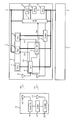
- FIG. It is a block diagram which shows the structural example of the power supply control system by Example 1.
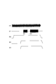
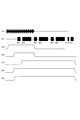
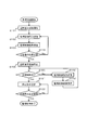
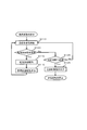
- FIG. It is an example of a signal waveform for demonstrating the operation example of a power supply control apparatus. It is a flowchart for demonstrating the operation example of a master controller. It is a flowchart for demonstrating the operation example of a radio signal detection part. It is a flowchart for demonstrating the operation example of a starting signal determination part. It is a flowchart for demonstrating the operation example of a communication part.
- FIG. 2 It is a block diagram which shows the structural example of the power supply control system by Example 2.
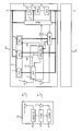
- FIG. It is a circuit diagram which shows the circuit structural example of a radio signal detection part, a starting signal determination part, and a power supply part.
- FIG. It is an example of a signal waveform for demonstrating the operation example of a power supply control apparatus. It is a flowchart for demonstrating the operation example of a communication part. It is an example of a signal waveform for demonstrating the operation example of a power supply control apparatus. It is a flowchart for demonstrating the operation example of a master controller.
- FIG. 4 shows the structural example of the power supply control system by Example 4.
- a power supply control system includes a battery, a power supply control device supplied with power from the battery, and a controller that communicates wirelessly with the power supply control device, and the power supply control device transmits a wireless activation signal transmitted by the controller. And a communication unit that wirelessly communicates with the controller, while the activation unit is receiving a wireless activation signal, the communication unit wirelessly Communication is carried out.
- a power control device includes a battery, an activation unit that receives a wireless activation signal, and a communication unit that transmits and receives a wireless communication signal, and the activation unit receives the wireless activation signal. Accordingly, the power supply from the battery to the communication unit is controlled, and the wireless communication signal is transmitted and received by the communication unit while the starting unit receives the wireless start signal.
- the battery may be provided outside the power supply control device.
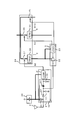
- FIG. 1 is a block diagram of a power supply control system for a device including a battery.
- the power control system includes one or a plurality of power control devices 1 and a master controller 15.
- the master controller 15 controls the operation of the power supply control device 1 using the wireless activation signal s0, and uses the wireless communication signal s1 to supply the power supply control device 1 to the battery cell 12 (BC1), the battery cell 13 (BC2), and the battery cell.
- 14 (BCn) is given a monitoring control instruction, and monitoring control results are collected.
- the number of battery cells is not limited to three, and may be any number as long as it is one or more.
- the battery cells included in them may be connected in series to each other, may be connected in parallel, or may not be connected.
- the master controller 15 transmits an antenna 16 for transmitting the wireless activation signal s0, an activation signal transmitter 18 for transmitting the wireless activation signal s0, an antenna 17 for transmitting and receiving the wireless communication signal s1, and the wireless communication signal s1.
- the communication part 20 which transmits / receives, the starting signal transmission part 18, and the control part 19 which controls the communication part 20 are provided.
- the master controller 15 is supplied with power from a higher system and operates. Therefore, the operation control of the master controller 15 is performed by a host system.
- the monitoring control results collected by the master controller 15 are transferred as they are to a higher-level system (not shown), or are processed into different information and transferred. Data transfer to the host system may be wired communication or wireless communication.
- the power supply control device 1 transmits / receives a wireless communication signal s1 to an antenna 2 for receiving a wireless activation signal s0, an activation unit 37 for receiving the wireless activation signal s0, an antenna 3 for transmitting / receiving the wireless communication signal s1.
- a communication unit 10 is provided.
- the power supply control device 1 includes a battery cell 12, a battery cell 13, a battery cell 14, a battery cell 12, the battery cell 13, and a battery cell monitoring control unit 11 that monitors and controls the battery cell 14, and a battery cell.
- a power supply unit 6 that supplies power to the wireless signal detection unit 4, the activation signal determination unit 5, and the communication unit 10 is provided.
- the activation unit 37 detects the signal strength of the received radio signal, demodulates the radio signal and outputs a baseband signal, and determines the data pattern of the baseband signal output from the radio signal detection unit 4 An activation signal determination unit 5 is provided.
- the battery cell 12, the battery cell 13, and the battery cell 14 are secondary batteries, such as a lithium ion battery, a sodium sulfur battery, or a lead battery, for example. When charging / discharging these secondary batteries, it may be assumed that if an excessive current is passed or if excessive charging or discharging is performed, the characteristics of the battery will deteriorate. Therefore, it is necessary for the master controller 15 to monitor the state of the battery cell and control it as necessary.
- the battery cell 12, the battery cell 13, and the battery cell 14 may be provided outside the power supply control device 1.
- the master controller 15 stops the transmission of the wireless activation signal s0 and the transmission of the monitoring control instruction by the wireless communication signal s1, changes the transmission cycle, or changes the monitoring control instruction according to the monitoring control result of the power supply control device 1.
- the power supply control device 1 is controlled to a suitable state by changing the contents.
- the wireless communication signal s1 transmitted by the power supply control device 1 cannot be received over a predetermined period or fails to be received at a predetermined rate, a sufficient monitoring control result cannot be obtained.
- connection switch (not shown) provided between the positive electrode of the battery cell 12 or the negative electrode of the battery cell 14 of the power supply control device 1 and the other power supply control device 1 or another device is disconnected, It is good to control so that each battery cell of the said power supply control apparatus 1 may not be charged / discharged.
- the battery cell monitoring control unit 11 operates with power supplied from the battery cell 12, the battery cell 13, and the battery cell 14. Further, based on the instruction of the master controller 15, for example, the voltage of each battery cell is measured, the battery cell having a high voltage is discharged in order to equalize the voltage of the battery cell, the voltage measuring function of the battery cell, Diagnose the discharge function. Therefore, the battery cell monitoring controller 11 is electrically connected to the positive electrode and the negative electrode of the battery cell 12, the battery cell 13, and the battery cell 14, and an AD for measuring voltage is connected to the connection location. A converter, a resistor for discharging, a reference voltage for diagnosis, and the like are provided.
- the power supply unit 6 includes a power supply circuit 7 that supplies power to the wireless signal detection unit 4, a power supply circuit 8 that supplies power to the activation signal determination unit 5, and a power supply circuit 9 that supplies power to the communication unit 10.
- the power supply circuit 7, the power supply circuit 8, and the power supply circuit 9 are preferably composed of regulators that step down the voltage. For example, a linear regulator, a switching regulator, a DC / DC converter, or the like.
- the wireless signal detection unit 4 Upon receiving the wireless activation signal s0 transmitted from the master controller 15, the wireless signal detection unit 4 detects the signal power of the wireless activation signal s0. When the detected signal power is larger than the predetermined power, the power supply unit control signal s2 is output and the power supply circuit 8 is operated. Since the power supply circuit 8 operates only when the power supply unit control signal s2 is input and supplies power to the activation signal determination unit 5, the activation signal determination unit 5 does not operate when the power supply unit control signal s2 is not output. Does not consume battery cell power.
- the wireless signal detection unit 4 that has received the wireless activation signal s0 that is larger than the predetermined power outputs the power supply unit control signal s2 and the baseband signal obtained by demodulating the wireless activation signal s0 to the activation signal determination unit 5. Output.
- the wireless activation signal s0 is, for example, an amplitude-modulated signal and has a predetermined data pattern.
- the power wireless signal detection unit 4 may operate using the power of the wireless activation signal s0 instead of the power supplied from the power supply circuit 7. Or you may operate
- the activation signal determination unit 5 starts operating when the power supply circuit 8 operates and starts supplying power.
- the baseband signal output from the wireless signal detection unit 4 is processed to restore the data pattern of the wireless activation signal s0. It is determined whether or not the data pattern matches a predetermined data pattern. If the data pattern matches, the power supply unit control signal s3 is output and the power supply circuit 9 is operated. Since the power supply circuit 9 operates only when the power supply unit control signal s3 is input and supplies power to the communication unit 10, the communication unit 10 does not operate when the power supply unit control signal s3 is not output, and the battery cell Does not consume power.
- the activation signal determination unit 5 to which a baseband signal matching a predetermined data pattern is input outputs a power supply unit control signal s3 and outputs a battery cell monitoring control unit control signal s4 to the battery cell monitoring control unit 11. Since the battery cell monitoring control unit 11 operates only when the battery cell monitoring control unit control signal s4 is input, the activation signal determining unit 5 outputs the battery cell monitoring control unit control signal s4 without receiving the wireless activation signal s0. If not, the battery cell power is not consumed.
- the predetermined data pattern includes, for example, an ID of the power supply control device 1 or an ID of a group composed of a plurality of power supply control devices 1.
- a data pattern may be encoded instead of the ID, and the code may be made unique for each power supply control device 1 or for each group.
- the activation signal determination unit 5 may be activated by receiving a power supply from the power supply circuit 8 at the same time as being reset so that the data pattern determination logic is initialized. For example, as in a POWER ON RESET function generally installed in a micro control unit, an internal register is initialized when a power supply is received, and the state is changed to a predetermined state. Alternatively, the power supply circuit 8 and the wireless signal detection unit 4 may output a reset signal to the activation signal determination unit 5.
- the communication unit 10 starts operating when the power supply circuit 9 operates and starts supplying power.
- a wireless communication signal is received via the antenna 3 and a monitoring control instruction is received from the master controller 15.
- the battery cell monitoring control unit 11 monitors and controls each battery cell, and receives the result from the battery cell monitoring control unit 11.
- a wireless communication signal (monitoring control result) is transmitted via the antenna 3, and the battery cell monitoring control result received from the battery cell monitoring control unit 11 is transmitted to the master controller 15.
- the received monitoring control result may be recorded in a memory, and may be transmitted to the master controller 15 together with a small number of wireless communication signals.
- the monitoring control instruction when the monitoring control instruction is composed of a plurality of monitoring control commands, the monitoring control instruction may be recorded in a memory, and the monitoring control command may be individually transmitted to the battery cell monitoring control unit 11.
- the communication unit 10 wirelessly communicates with the master controller 15 and also controls the battery cell monitoring control unit 11, it can be configured by a micro control unit equipped with a wireless communication function.
- the communication unit 10 may receive power supply from the power supply circuit 9 and may be activated at the same time as the power supply circuit 9 to transition to a predetermined state. For example, as in a POWER ON RESET function generally mounted on a micro control unit, an internal register is initialized when a power supply is received, and a transition to a reception standby state is made. Alternatively, the power supply circuit 9 and the activation signal determination unit 5 may output a reset signal to the communication unit 10. The communication unit 10 may output the battery cell monitoring control unit control signal s4 instead of the activation signal determination unit 5. In this way, when the content of the monitoring control instruction is only communication, it is sufficient that only the communication unit 10 is operating, so that the operation of the battery cell monitoring control unit 11 can be stopped.
- the monitoring control instruction transmitted from the master controller 15 includes the ID of the power supply control device 1 or includes the ID of a group composed of a plurality of power supply control devices 1. By doing so, only one specific power control device 1 or a specific group of power control devices 1 can be monitored and controlled. Thereby, it is possible to cause the power supply control device 1 that does not require monitoring control to perform monitoring control, and to reduce unnecessary power consumption and communication.
- a data pattern may be encoded instead of the ID, and the code may be made unique for each power supply control device 1 or for each group. By encoding, even when a plurality of power supply control devices 1 and master controller 15 communicate simultaneously, interference of wireless communication signals can be reduced.
- the supervisory control instruction wireless communication signal s1 is periodically transmitted from the master controller 15, or is transmitted irregularly when a specific condition is satisfied.
- the power supply control device 1 is also periodically monitored and controlled or irregularly monitored and controlled.
- the monitoring control instruction transmitted from the master controller 15 does not necessarily include transmitting the monitoring control result to the master controller 15.
- the monitoring control result may be recorded in a memory included in the communication unit 10 or the battery cell monitoring control unit 11, and the monitoring control result may be transmitted once for a plurality of monitoring control instructions.
- the power supply control device 1 can reduce the number of transmissions of the wireless communication signal s1, and can reduce power consumption.
- the transmission timing of the wireless communication signal s1 and the monitoring control content can be flexibly changed in accordance with the installation environment, usage status, and the like of the power supply control device 1.
- the wireless communication signal s1 as the monitoring control result is periodically transmitted from the power supply control device 1, or is transmitted irregularly when a specific condition is satisfied.
- transmission is performed at a timing predetermined by an ID or the like, transmission is performed at a timing instructed by a supervisory control instruction, or transmission is performed so that transmission signals do not collide with each other. It transmits after confirming whether the other power supply control apparatus 1 has not transmitted before.
- the antenna 2 is preferably installed in the null point direction of the antenna 3.
- a radio wave propagation loss from the antenna 3 to the antenna 2 may be increased by installing a conductor plate between the antenna 2 and the antenna 3.
- the wireless communication signal s1 transmitted from the antenna 3 is received by the antenna 2 installed at a short distance, there is a possibility that the wireless activation signal s0 interferes with the data pattern of the wireless activation signal s0.
- the antenna 2 is installed in a direction in which the radio communication signal s1 transmitted from the antenna 3 is greatly attenuated and propagates.
- the antenna 17 is preferably installed in the null point direction of the antenna 16.
- a radio wave propagation loss from the antenna 16 to the antenna 17 may be increased, for example, by installing a conductor plate between the antenna 17 and the antenna 16.
- the antenna 17 is installed in a direction in which the radio activation signal s0 transmitted from the antenna 16 is greatly attenuated and propagates.
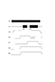
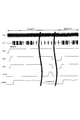
- FIG. 2 is a signal waveform example for explaining an operation example of the power supply control device 1.
- the time series of the wireless activation signal s0, the wireless communication signal s1, the power supply unit control signal s2, the power supply unit control signal s3, and the battery cell monitoring control unit control signal s4 is shown.
- the wireless activation signal s0 is a signal obtained by amplitude-modulating a predetermined data pattern, for example.
- the wireless communication signal s1 includes a monitoring control instruction signal s5 and a monitoring control result signal s6, and is, for example, a frequency-modulated signal.
- the power supply unit control signal s2, the power supply unit control signal s3, and the battery cell monitoring control unit control signal s4 are all preferably digital signals.
- the wireless activation signal s0 and the wireless communication signal s1 can be transmitted and received simultaneously.
- the data pattern of the monitoring control instruction and the monitoring control result is set so that the signal waveform of the radio communication signal s1 is not determined to be the same data pattern as the radio activation signal s0. It is advisable to set restrictions on signal length, signal interval, etc. Further, in order to reduce the possibility that the wireless signal detection unit 4 detects the wireless communication signal s1 and operates the activation signal determination unit 5, the transmission power of the wireless communication signal s1 should be sufficiently smaller than the wireless activation signal s0. .
- the wireless activation signal s0 and the wireless communication signal s1 are probabilities that the received power is lowered or the data pattern is wrong due to the influence of the radio wave propagation environment between the master controller 15 and the power supply control device 1, for example, fading or interference. In order to reduce this, it is preferable to change the modulation method, frequency, code, etc. used. These changes are performed by instructing the power supply control device 1 from the master controller 15 by the wireless activation signal s0 or the wireless communication signal s1, or are performed according to a predetermined sequence.
- the power supply unit control signal s2, the power supply unit control signal s3, and the battery cell monitoring control unit control signal s4 may be used, for example, such that the target is stopped when the level is Low and the target is operated when the level is High. In this way, the activation signal determination unit 5 and the communication unit 10 to which no power is supplied from the power supply unit 6 do not output a high level signal, and thus the activation signal is received in a state where the wireless activation signal s0 is not received. It can prevent that the determination part 5, the communication part 10, and the battery cell monitoring control part 11 operate
- the wireless signal detection unit 4 detects the wireless activation signal s0 and outputs a high-level power supply unit control signal s2.
- the activation signal determination unit 5 starts its operation.
- the activation signal determination unit 5 determines the data pattern of the wireless activation signal s0 and outputs a high-level power supply unit control signal s3 and a battery cell monitoring control unit control signal s4. By outputting the high-level power supply unit control signal s3 and the battery cell monitoring control unit control signal s4, the communication unit 10 and the battery cell monitoring control unit 11 start operation.
- the communication unit 10 receives the monitoring control instruction signal s5, and the battery cell monitoring control unit 11 performs predetermined monitoring control. Then, the communication unit 10 transmits a monitoring control result signal s6.
- the master controller 15 stops the transmission of the wireless activation signal s0.
- the wireless activation signal s0 is no longer received by the power supply control device 1, the activation signal determination unit 5 cannot determine the data pattern of the wireless activation signal s0, and outputs the high-level power supply unit control signal s3 and the monitoring control unit control signal s4. Stop and set to Low level. Thereby, the communication part 10 and the battery cell monitoring control part 11 stop operation
- the wireless signal detection unit 4 cannot detect the wireless activation signal s0, stops the output of the high-level power supply unit control signal s2, and sets it to the Low level. Thereby, the activation signal determination unit 5 stops the operation. As described above, when the transmission of the wireless activation signal s0 is stopped, the activation signal determination unit 5, the communication unit 10, and the battery cell monitoring control unit 11 of the power supply control device 1 stop operating.
- the wireless activation signal s 0 is common to all power control devices 1, common to some power control devices 1, or individual power control devices 1. Or individual. If the wireless activation signal s0 is common to all the power supply control devices 1, all the power supply control devices 1 can be activated with one wireless activation signal s0. At this time, the activation determination units 5 included in all the power supply control devices 1 have a common predetermined data pattern. Further, if the wireless activation signal s0 is common to some of the plurality of power supply control devices 1, it is selectively activated for each group of several power supply control devices 1 according to the application, installation environment, use environment, and the like. be able to.
- the activation determination unit 5 provided in all the power supply control devices 1 has a predetermined data pattern common to each group. Further, when the wireless activation signal s0 is individually provided for each power supply control device 1, each power supply control device 1 can be selectively activated. At this time, the activation determination units 5 included in all the power supply control devices 1 have individual predetermined data patterns. These predetermined data patterns may have only one, but if the above three patterns are provided, activation according to the situation becomes possible.
- the monitoring control instruction signal s5 is common to all the power supply control devices 1 or common to some of the plurality of power supply control devices 1, like the wireless activation signal s0. Or individual power supply control devices 1.
- an ID of the communication partner may be included in a signal and transmitted.
- the ID included in the monitoring control instruction signal s5 is an ID common to all the power supply control devices 1, an ID common to some of the power supply control devices 1, or an individual ID for each power supply control device 1.
- the monitoring control result signal s6 may be transmitted using TDMA, CSMA / CA, etc., which are general multiple access technologies. Since the monitoring control result signal s6 is received by the same master controller 15, it is controlled so that the signals do not collide with each other.
- the wireless signal detection unit 4 may output a high-level power supply unit control signal s2 when the detected signal power is larger than the predetermined power over a predetermined time. By doing so, even if high power noise is instantaneously generated from an inverter or the like, there is no false detection. In addition, when the detected signal power is smaller than the predetermined power over a predetermined time, the output of the high-level power source control signal s2 may be stopped and set to the Low level. By doing so, the operation of the activation determination unit 5 can be continued even if the reception power of the wireless activation signal s0 is instantaneously reduced without intention.
- the predetermined time set in the wireless signal detection unit 4 may be determined in advance, but is changed according to the situation of the power supply control device 1, and the power is supplied from the master controller 15 by the wireless activation signal s0 or the wireless communication signal s1. It may be set by instructing the control device 1.
- the status of the power supply control device 1 includes, for example, a difference in status such as operation, storage and maintenance of the power supply control device 1, a difference in radio wave propagation environment between the master controller 15 and the power supply control device 1, monitoring control This is due to a difference in the number of power supply control devices 1 to be operated. For a predetermined time, it is preferable to output a setting signal from the activation signal determination unit 5 or the communication unit 10 to the wireless signal detection unit 4 so as to be held in the wireless signal detection unit 4.
- the activation signal determination unit 5 determines that the baseband signal input from the wireless signal detection unit 4 matches a predetermined data pattern for a predetermined time
- the monitoring control unit control signal s4 may be output.
- the high-level power source control signal s3 and the battery cell monitoring control unit control signal s4 may be output. By doing so, noise is not erroneously detected.
- the output of the high-level power supply unit control signal s3 and the battery cell monitoring control unit control signal s4 may be stopped and set to the low level. Alternatively, when it is determined that the data pattern of the wireless activation signal s0 does not match the predetermined data pattern more than a predetermined number of times, the output of the high-level power source control signal s3 and the battery cell monitoring control unit control signal s4 is stopped. , Low level is good.
- the operation of the communication unit 10 and the battery cell monitoring control unit 11 is continued even if the reception power of the wireless activation signal s0 is instantaneously reduced or the data pattern is erroneous due to noise. be able to. Or even if the radio
- the predetermined time or the predetermined number of times set in the activation signal determination unit 5 may be determined in advance, but is changed according to the situation of the power supply control device 1, and is mastered by the wireless activation signal s0 or the wireless communication signal s1.
- the status of the power supply control device 1 includes, for example, a difference in status such as operation, storage and maintenance of the power supply control device 1, a difference in radio wave propagation environment between the master controller 15 and the power supply control device 1, monitoring control This is due to a difference in the number of power supply control devices 1 to be operated.
- a setting signal is output from the communication unit 10 to the activation signal determination unit 5 and held in the activation signal determination unit 5.
- the activation signal determination unit 5 may detect and hold the setting from the data pattern included in the wireless activation signal s0.
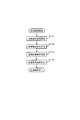
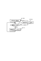
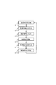
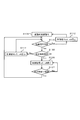
- FIG. 3 is a flowchart for explaining an operation example of the master controller 15.
- the master controller 15 starts predetermined monitoring control according to an instruction from the host system, the status of the power supply control device 1, and the status of the master controller 15.
- the master controller 15 starts transmitting a wireless activation signal (S101).
- the master controller 15 transmits a monitoring control instruction to the power supply control apparatus 1 after a time when the communication unit 10 of the power supply control apparatus 1 is expected to start operating (S102).
- the master controller 15 receives the monitoring control result from the power supply control apparatus 1 which implemented the monitoring control of the battery cell (S103).
- the master controller 15 that has received the monitoring control result and completed the predetermined monitoring control stops the transmission of the activation signal (S104). Thus, the monitoring control is finished.
- the supervisory control instruction transmission S102 and the supervisory control result reception S103 may be performed a plurality of times.
- the supervisory control instruction transmission S102 is omitted. It is also possible.
- the monitoring control result reception S103 does not necessarily have to be performed, and the power supply control device 1 may only store the monitoring control result in the memory of the communication unit 10.
- the start and end of the monitoring control may be determined by the master controller 15 such that a predetermined condition is satisfied, or the monitoring control is started or ended by a signal input from another system (not shown) to the control unit 19. May be.
- the predetermined condition is, for example, that a predetermined period has elapsed or that a predetermined monitoring control result has been obtained.
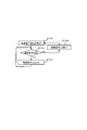
- FIG. 4 is a flowchart for explaining an operation example of the wireless signal detection unit 4.
- the wireless signal detector 4 is always operating so that the wireless activation signal s0 can be detected at any time (S105).
- the wireless signal detection unit 4 detects whether a wireless signal is received with a predetermined signal power or higher (S106). If a wireless signal is detected, the wireless signal may be the wireless activation signal s0, and therefore it is necessary to cause the activation signal determination unit 5 to determine whether the wireless signal is the wireless activation signal s0. Therefore, the wireless signal detection unit 4 outputs the power supply unit control signal s2 to the high level (S107). The wireless signal detection unit 4 outputs the power supply unit control signal s2 and performs the wireless signal detection S106 again.
- the wireless signal detection unit 4 sets the power supply unit control signal s2 to the Low level (S108).
- the radio signal detection unit 4 sets the power supply unit control signal s2 to the low level, returns to the radio signal detection unit operation S105 again, and proceeds to the radio signal detection S106.
- the wireless signal detection unit 4 continues to detect the presence or absence of a wireless signal, and changes the power supply unit control signal s2 to a high level or a low level according to the result.
- the power of the radio signal may be leveled at a predetermined time, the radio signal detection S106 may be performed at a predetermined time interval, or the result of the radio signal detection S106 may be held for a predetermined time.
- the time constant of the input or output of the circuit for detecting the radio signal power is set low, and the change in the signal power of the input radio signal or the signal of the detection result is moderated.
- the time constant may be a fixed value, but may be configured so that the setting can be changed according to the situation of the power supply control device 1.
- the time constant is preferably set according to an instruction from the master controller 15 while the activation signal determination unit 5 and the communication unit 10 are operating.
- FIG. 5 is a flowchart for explaining an operation example of the activation signal determination unit 5.
- the activation signal determination unit 5 operates while power is supplied from the power supply circuit 8 (S109). First, the activation signal determination unit 5 determines whether the data pattern of the wireless signal detected by the wireless signal detection unit 4 matches a predetermined data pattern (S110). If the data patterns match, the radio signal is an activation signal. Therefore, the activation signal determination unit 5 outputs the power supply unit control signal s3 and the battery cell monitoring control unit control signal s4 to the high level in order to activate the communication unit 10 and the battery cell monitoring control unit 11 (S111).
- the activation signal determination unit 5 outputs the power supply unit control signal s3 and the battery cell monitoring control unit control signal s4, and performs the activation signal determination S110 again. If the data patterns do not match in the activation signal determination S110, the activation signal determination unit 5 sets the power supply unit control signal s3 and the battery cell monitoring control unit control signal s4 to the low level (S112). The activation signal determination unit 5 sets the power supply unit control signal s3 and the battery cell monitoring control unit control signal s4 to the Low level, returns to the activation determination unit operation S109 again, and proceeds to the activation signal determination S110.
- the power supply unit control signal s3 and the battery cell monitoring control unit control signal s4 are changed to a high level or a low level.
- the result of the activation signal determination S110 is not determined by a single determination result, but may be determined by a predetermined time or number of determination results. For example, if the data pattern continuously matches for a predetermined time or number of times, it is determined that the data pattern matches, if it does not match continuously, it is determined that it does not match, or if it matches at a predetermined rate It is determined that they match.
- the determination threshold value may be a fixed value, but may be configured so that the setting can be changed according to the state of the power supply control device 1.
- the determination threshold value may be set according to an instruction from the master controller 15 while the activation signal determination unit 5 and the communication unit 10 are operating.
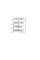
- FIG. 6 is a flowchart for explaining an operation example of the communication unit 10.
- the communication unit 10 operates while power is supplied from the power supply circuit 9.
- the communication unit 10 transitions to a reception standby state in order to receive a monitoring control instruction from the master controller 15 (S113).
- the communication unit 10 receives the monitoring control instruction transmitted from the master controller 15 (S114).
- the communication unit 10 performs battery cell monitoring control by the battery cell monitoring control unit 11 according to the instruction (S115), and transmits the result to the master controller 15 (116). Thereafter, the process returns to the reception standby S113 again to wait for the next monitoring control instruction.
- the communication unit 10 receives the monitoring control instruction from the master controller 15, performs the monitoring control, and transmits the monitoring control result while power is supplied. Further, the monitoring control instruction received by the monitoring control instruction reception S114 may be recorded in the memory, and the monitoring control may be performed S115 based on the recorded instruction. Further, the result of the monitoring control execution S115 may be recorded in a memory, and the monitoring control result may be transmitted S116 at a predetermined timing or a timing instructed by a monitoring control instruction.
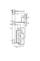
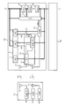
- FIG. 7 is a circuit diagram illustrating a circuit configuration example of the wireless signal detection unit 4 and the activation signal determination unit 5.
- the wireless signal detection unit 4 includes a rectifier circuit 32 and a comparator 21.
- the rectifier circuit 32 includes diodes D1 and D2, capacitors C1 and C2, and a resistor R1.
- the wireless activation signal s0 is rectified by the diodes D1 and D2, and charges are stored in the capacitors C1 and C2.
- the capacitor C1 is smaller than the capacitor C2, and the carrier component of the wireless activation signal s0 is rectified at the terminal of the capacitor C1 by being connected via the resistor R1, but the component is much lower in frequency than the carrier component.
- the baseband component is configured to remain somewhat.
- All of the terminals including the baseband component are rectified at the terminal of the capacitor C2, and a DC voltage corresponding to the signal power of the wireless activation signal s0 is generated. In this way, the signal power and baseband signal of the wireless activation signal s0 are obtained.
- the baseband signal is output to the activation signal determination unit 5.
- the DC voltage corresponding to the signal power of the wireless activation signal s0 generated at the terminal of the capacitor C2 is compared with a predetermined threshold voltage by the comparator 21.
- the comparator 21 When the DC voltage is higher than the threshold voltage, that is, when the signal power of the wireless activation signal s0 is larger than the predetermined power, the comparator 21 outputs the high-level power source control signal s2, and the DC voltage is higher than the threshold voltage. Is lower, that is, when the signal power of the wireless activation signal s0 is smaller than the predetermined power, the comparator 21 outputs the power supply unit control signal s2 of Low level.
- the output of the comparator 21 may be frequently inverted due to the influence of noise.
- the threshold value of the comparator 21 should have a hysteresis characteristic. Further, by sufficiently increasing the resistance R1 and the capacitance C2, the influence of noise can be leveled, and the possibility that the output of the comparator 21 is frequently inverted can be reduced.
- the hysteresis characteristic, the resistor R1, and the capacitor C2 may be changed by arranging elements in an array and connecting them with a switch.
- the power supply circuit 7 supplies power to the comparator 21 and applies a bias voltage to the diode D1. By doing so, the detection sensitivity of the wireless activation signal s0 can be increased.
- the power supply voltage of the comparator 21 may be a DC voltage generated at the terminal of the capacitor C2, or the application of the bias voltage to the diode D1 may be stopped.
- the activation signal determination unit 5 includes an amplifier 22 and a logic circuit 23.
- the baseband signal output from the rectifier circuit 32 is amplified by the amplifier 22 to a signal level that can be processed by the logic circuit 23.
- a predetermined data pattern is recorded in the logic circuit 23 in advance, and determination is made based on whether or not it matches the data pattern. Note that a plurality of data patterns may be recorded and it may be determined which one matches. For example, in addition to the self ID, the ID of the group including the self, the ID corresponding to the priority of the monitoring control, and the like.
- the amplitude of the baseband signal varies depending on the signal power of the wireless activation signal s0. Therefore, the amplifier 22 may have a variable amplification factor.
- the logic circuit 23 determines the levels of the power supply unit control signal s3 and the battery cell monitoring control unit control signal s4 through the determination of the data pattern a plurality of times. It is good to do.
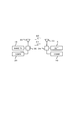
- FIG. 8 is a block diagram illustrating a configuration example of the antenna and its peripheral portion of the master controller 15 and the power supply control device 1.
- the wireless signal detection unit 4 and the communication unit 10 are connected to the antenna 33 via the signal separation unit 34.
- the activation signal transmission unit 18 and the communication unit 20 are connected to the antenna 35 via the signal separation unit 36.
- the antenna 33 and the antenna 35 are antennas capable of transmitting and receiving the wireless activation signal s0 and the wireless communication signal s1. When the frequencies of the wireless activation signal s0 and the wireless communication signal s1 are different, the antenna 33 and the antenna 35 are antennas having good propagation characteristics at these frequencies.
- the signal separation unit 34 passes the wireless activation signal s0 received by the antenna 33 to the wireless signal detection unit 4, passes the wireless communication signal s1 received by the antenna 33 to the communication unit 10, and is transmitted from the communication unit 10.
- the result signal s6 is passed through the antenna 33, and the monitoring control result signal s6 transmitted from the communication unit 10 is not allowed to pass through the radio signal detection unit 4 so much.
- the signal separation unit 34 includes, for example, a circulator, a duplexer, a filter, and the like. Alternatively, the same function can also be realized by means such as a modulation method or encoding instead of being configured as a part. These functions may be realized as part of the functions of the wireless signal detection unit 4 and the communication unit 10.
- the signal separation unit 36 separates the wireless activation signal s0 and the wireless communication signal s1.
- the activation signal transmitted from the activation signal transmitting unit 18 is passed through the antenna 35, and the activation signal transmitted from the activation signal transmitting unit 18 is not allowed to pass through the communication unit 20 and the radio communication signal s1 received by the antenna 35 is communicated.
- the signal separation unit 36 includes, for example, a circulator, a duplexer, a filter, and the like. Alternatively, the same function can also be realized by means such as a modulation method or encoding instead of being configured as a part. These functions may be realized as part of the functions of the activation signal transmission unit 18 and the communication unit 20.
- the power supply control device 1 is configured to operate while receiving the wireless activation signal s0 and stop when not receiving, but reverses the logic and stops while receiving the wireless activation signal s0 and does not receive it. It is also possible to have a configuration that operates inside.
- the logic of the power supply unit control signal s2, the power supply unit control signal s3, and the battery cell monitoring control unit control signal s4 may be inverted.
- the configuration of the power supply control system according to the present embodiment when the configuration of the power supply control system according to the present embodiment is applied, it is possible to simultaneously perform start / stop control by radio signals and battery cell monitoring control.
- the start / stop control can be stably performed without depending on the monitoring control content, the execution time, the execution cycle, and the like of the battery cell.
- the activation determination circuit, the communication unit, and the battery cell monitoring control unit can be stopped, and the power consumed from the battery cell can be reduced.
- the wireless activation signal and the wireless communication signal include the ID of the power supply control device, it is possible to perform start / stop control and battery cell monitoring control for any power supply control device.
- the determination threshold of the activation signal is set to the number of receptions at a predetermined number of times or the number of receptions within a predetermined period, it is possible to prevent erroneous activation and erroneous stop.
- the radio activation signal and the radio communication signal by a circulator or modulation method, it is possible to perform activation / stop control by radio signal and battery cell monitoring control simultaneously even if one antenna is shared. become.
- FIG. 9 is a block diagram illustrating a configuration example of a power supply control system of a device including a battery.
- the power supply control device 38 includes a power supply unit 24, a power supply circuit 25, and a power supply unit 26.
- the wireless signal detection unit 4 operates with power supplied from the power supply unit 26, and the battery cell monitoring control unit 11 operates with power supplied from the power supply circuit 25.
- the activation signal determination unit 5 outputs the power supply unit control signal s3 and the power supply unit control signal s13 to operate the power supply circuit 9 and the power supply circuit 25.
- the power supply circuit 25 Since the power supply circuit 25 operates only when the power supply unit control signal s13 is input and supplies power to the battery cell monitoring control unit 11, the battery cell monitoring control unit 11 operates when the power supply unit control signal s13 is not output. And does not consume battery cell power.
- the power supply unit 26 supplies power from a power source different from that of the battery cells 12, 13, and 14. For example, a coin-type primary battery or a small secondary battery is used as a power source. Alternatively, a power generation element such as a solar power generation element, a vibration power generation element, or a thermoelectric conversion element may be used as the power source.
- the power supply unit 26 may be configured to supply power not only to the wireless signal detection unit 4 but also to the activation signal determination unit 5 and the communication unit 10.
- the starting unit 37, the communication unit 10, the battery cell monitoring control unit 11, and the like may be configured to use power supply from the power supply unit 26 and the power supply unit 24 in combination.
- the part that operates at a high voltage of the battery cell monitoring control unit 11 operates with power supplied from the battery cells 12, 13, and 14, and the part that operates at a low voltage of the battery cell monitoring control unit 11 and the communication unit 10
- it operates with power supplied from the power supply unit 26. By doing so, the power supplied from the battery cells 12, 13, and 14 can be reduced.
- FIG. 10 is a circuit diagram showing a circuit configuration example of the wireless signal detection unit 4, the activation signal determination unit 5, the power supply unit 24, and the power supply unit 26.
- the power supply unit 26 includes a coin-type primary battery, applies a bias voltage to the diode D1, and applies a power supply voltage to the comparator 21.
- a regulator for adjusting the voltage may be provided between the coin-type primary battery and the diode D1 or the comparator 21. By providing the regulator, it is possible to keep the bias voltage and the power supply voltage constant even if the voltage of the primary battery changes according to the amount of remaining charge.
- the power circuit 8 includes a switch 27 and a regulator 28, the power circuit 9 includes a switch 29 and a regulator 30, and the power circuit 25 is a switch.
- the power supply unit control signal s2 output from the wireless signal detection unit 4 controls on / off of the switch 27.
- the switch 27 When the signal power of the radio signal is larger than the predetermined power, the high-level power source control signal s2 is output and the switch 27 is turned on.
- the switch 27 is turned off by the low-level power source control signal s2.
- the switch 27 When the switch 27 is turned on, power is supplied to the regulator 28 and the regulator 28 starts to operate.
- the regulator 28 that has started operation starts supplying power to the activation signal determination unit 5, and the activation signal determination unit 5 starts operation.
- the switch 27 is preferably installed between the regulator 28 and the battery cell 12. When the switch 27 is off, power is not supplied to the regulator 28, so that the regulator 28 does not consume standby current or the like, and the current consumption during standby for receiving the wireless activation signal s0 can be kept low.
- the power supply unit control signal s3 output from the activation signal determination unit 5 controls on / off of the switch 29.
- a high-level power source control signal s3 is output and the switch 29 is turned on.
- the switch 29 is turned off by the low-level power source control signal s3.
- the switch 29 is turned on, power is supplied to the regulator 30 and the regulator 30 starts operating.
- the regulator 30 that has started operation starts supplying power to the communication unit 10, and the communication unit 10 starts operation.
- the switch 29 is preferably installed between the regulator 30 and the battery cell 12. When the switch 29 is turned off, power is not supplied to the regulator 30, so that the regulator 30 does not consume standby current or the like, and current consumption during reception standby of the wireless activation signal s0 can be kept low.
- the power supply unit control signal s13 output from the activation signal determination unit 5 controls on / off of the power supply circuit (switch) 25.
- a high-level power supply control signal s13 is output and the power supply circuit 25 is turned on.
- the power supply circuit 25 is turned off by the low-level power supply control signal s13.
- the power supply circuit 25 is turned on, power is supplied to the battery cell monitoring control unit 11 and the battery cell monitoring control unit 11 starts operating. If the power supply circuit 25 is installed between the battery cell monitoring control unit 11 and the battery cell 12, power is not supplied to the battery cell monitoring control unit 11 when the power supply circuit 25 is off. Does not consume standby current or the like, and current consumption during reception standby of the wireless activation signal s0 can be kept low.
- the power supply circuit 25 may also be configured with a switch and a regulator, like the power supply circuits 8 and 9.
- the radio signal detection unit 4 may be operated by the power obtained by rectifying the received radio signal by the rectifier circuit 32 in addition to the operation by the power of the power supply unit 26.
- the power supply unit 26 is not necessary, and the bias voltage applied to the diode D1 is preferably set to the same potential as the negative terminals of the capacitors C1 and C2 (the terminal not connected to the resistor R1).
- the comparator 21 may operate using the DC voltage generated by the rectifier circuit 32 as a power supply voltage. Further, the comparator 21 may operate using both the power obtained by the rectifier circuit 32 and the power of the power supply unit 26.
- the bias voltage of the diode D1 may be applied from the power supply unit 26, and the power supply voltage of the comparator 21 may be applied from the rectifier circuit 32.
- the start / stop control can be stably performed without depending on the monitoring control content, the execution time, the execution cycle, and the like of the battery cell.
- the activation determination circuit, the communication unit, and the battery cell monitoring control unit can be stopped, and the power consumed from the battery cell can be reduced.
- the power consumption of the wireless signal detection unit can be supplied from a power source different from the battery cell, and the power consumed from the battery cell can be further reduced.
- the wireless activation signal and the wireless communication signal include the ID of the power supply control device, it is possible to perform start / stop control and battery cell monitoring control for any power supply control device.
- the determination threshold of the activation signal is set to the number of receptions at a predetermined number of times or the number of receptions within a predetermined period, it is possible to prevent erroneous activation and erroneous stop.
- by separating the radio activation signal and the radio communication signal by a circulator or modulation method it is possible to perform activation / stop control by radio signal and battery cell monitoring control simultaneously even if one antenna is shared. become. It is also possible to implement in combination with the first embodiment.
- FIG. 11 is a block diagram illustrating a configuration example of a power supply control system of a device including a battery.
- the power supply control device 39 includes a control signal synthesis unit 31.
- the control signal combining unit 31 is configured by, for example, OR logic, and outputs a high level power supply unit control signal s8 when either the power supply unit control signal s3 or the power supply unit control signal s7 is at a high level. 9 is operated. Since the power supply circuit 9 operates only when a high-level power supply unit control signal s8 is input and supplies power to the communication unit 10, the communication unit 10 operates in a state where the high-level power supply unit control signal s8 is not output. And does not consume battery cell power.
- the control signal combining unit 31 is preferably supplied with power from the power supply circuit 7 or the power supply circuit 8. Alternatively, power may be supplied using the power supply circuit 8 and the power supply circuit 9 in combination. Alternatively, power may be supplied from both the power supply unit control signal s3 and the power supply unit control signal s7.
- the activation signal determination unit 5 outputs a high-level power supply unit control signal s3.
- the communication unit 10 outputs a high-level power supply unit control signal s7 for a predetermined period during which the power supply circuit 9 is not desired to be stopped.
- the predetermined period in which the power supply circuit 9 is not desired to be stopped is, for example, being in communication with the master controller 15, or being monitored or controlled by the battery cell monitoring controller 11, or instructed by the master controller 15. Other operations are in progress.
- the power supply unit control signals s3 and s7 are at the low level.
- FIG. 12 is a signal waveform example for explaining an operation example of the power supply control device 39.
- a time series of the wireless activation signal s0, the wireless communication signal s1, the power supply unit control signals s2, s3, s7, s8, and the battery cell monitoring control unit control signal s9 is shown.
- the wireless communication signal s1 includes a monitoring control instruction signal s5 and a monitoring control result signal s6.
- the power supply unit control signals s2, s3, s7, s8 and the battery cell monitoring control unit control signal s9 are all digital signals.
- the wireless signal detection unit 4 detects the wireless activation signal s0 and outputs a high-level power supply unit control signal s2.
- the activation signal determination unit 5 starts its operation.
- the activation signal determination unit 5 determines the data pattern of the wireless activation signal s0 and outputs a high-level power supply unit control signal s3.
- the control signal synthesizer 31 takes the OR logic of the high-level power supply control signal s3 and the low-level power supply control signal s7, and outputs a high-level power supply control signal s8.
- the communication unit 10 starts operating.
- the communication unit 10 outputs a high-level battery cell monitoring control unit control signal s9.
- the high level battery cell monitoring control unit control signal s9 is output, the battery cell monitoring control unit 11 starts its operation. Thereafter, the communication unit 10 receives the monitoring control instruction signal s5.
- the communication unit 10 outputs a high-level power supply unit control signal s7.
- the power supply unit control signal s7 is set to the high level until the battery cell monitoring control by the battery cell monitoring control unit 11 and the transmission of the monitoring control result signal s6 by the communication unit 10 are completed.
- the power source control signal s3 changes to the low level.
- the control signal synthesizer 31 continues to output the high-level power supply unit control signal s8 because the power supply unit control signal s7 is at the high level. As a result, the power supply to the communication unit 10 is continued and the monitoring control result signal s6 can be transmitted.
- the master controller 15 stops transmitting the wireless activation signal s0 when the monitoring control is completed.
- the activation signal determination unit 5 cannot determine the data pattern of the wireless activation signal s0, stops the output of the high-level power supply unit control signal s3, and sets it to the Low level.
- the control signal synthesis unit 31 also stops the output of the high level power supply unit control signal s8 and sets it to the low level. Then, the operation of the communication unit 10 stops, and the battery cell monitoring control unit control signal s9 becomes a low level.
- the operation of the battery cell monitoring control unit 11 is also stopped. Further, the wireless signal detection unit 4 cannot detect the wireless activation signal s0, stops the output of the high-level power supply unit control signal s2, and sets it to the Low level. As a result, the operation of the activation signal determination unit 5 is stopped. As described above, when the transmission of the wireless activation signal s0 is stopped, the activation signal determination unit 5, the communication unit 10, and the battery cell monitoring control unit 11 of the power supply control device 39 stop operating.
- FIG. 13 is a flowchart for explaining an operation example of the communication unit 10.
- the communication unit 10 operates while power is supplied from the power supply circuit 9.
- the communication unit 10 transitions to a reception standby state in order to receive a monitoring control instruction from the master controller 15 (S113).
- the communication unit 10 receives the monitoring control instruction transmitted from the master controller 15 (S114).
- the communication unit 10 outputs the high-level power supply unit control signal s7, and operates the power supply circuit 9 regardless of the determination result of the activation signal determination unit 5 (S117).
- the potential level of the power supply unit control signal s7 may be determined according to a monitoring control instruction from the master controller 15.
- the communication unit 10 performs battery cell monitoring control according to the received monitoring control instruction (S115), and transmits the result to the master controller 15 (116). Thereafter, the communication unit 10 returns the power supply unit control signal s7 to the low level, and leaves the operation control of the power supply circuit 9 to the activation signal determination unit 5 (S118). Then, the process returns to the reception standby S113 again, and the communication unit 10 waits for the next monitoring control instruction. As described above, while the power is supplied, the monitoring control instruction is received from the master controller 15, the power supply unit control signal s7 is output, the monitoring control is performed, and the monitoring control result is transmitted.
- FIG. 14 is a signal waveform example for explaining an operation example of the power supply control device 39.
- a time series of the wireless activation signal s0, the wireless communication signal s1, the power supply unit control signals s2, s3, s7, s8, and the battery cell monitoring control unit control signal s9 is shown.
- the wireless communication signal s1 includes a monitoring control instruction signal s5, a monitoring control result signal s6, a wireless stop signal s10, and a delivery confirmation signal s11.
- the power supply unit control signals s2, s3, s7, s8 and the battery cell monitoring control unit control signal s9 are all digital signals in this example.
- the wireless signal detection unit 4 detects the wireless activation signal s0 and outputs a high-level power supply unit control signal s2.
- the activation signal determination unit 5 which has started the operation determines the data pattern of the wireless activation signal s0 and outputs a high-level power supply unit control signal s3.
- the control signal synthesizer 31 takes the OR logic of the high-level power supply control signal s3 and the low-level power supply control signal s7, and outputs a high-level power supply control signal s8.
- the communication unit 10 that has started the operation outputs a high-level battery cell monitoring control unit control signal s9. Thereafter, the communication unit 10 receives the monitoring control instruction signal s5.
- the communication unit 10 outputs a high-level power supply unit control signal s7.
- the power supply unit control signal s7 is set to the high level until the wireless stop signal s10 is received from the master controller 15 and the delivery confirmation signal s11 is transmitted to the master controller 15. Then, even if the master controller 15 stops the transmission of the wireless activation signal s0 and the power supply unit control signals s2 and s3 are at the low level, the control signal synthesis unit 31 has the high level because the power supply unit control signal s7 is at the high level.
- the power supply unit control signal s8 is continuously output.
- the master controller 15 can stop the transmission of the wireless activation signal s0, and can reduce power consumption or increase the frequency at which the wireless communication signal s1 can be used.
- the master controller 15 transmits a wireless stop signal s10.
- the power supply control device 39 that has received the wireless stop signal s10 transmits a delivery confirmation signal s11, and sets the power supply unit control signal s7 and the battery monitoring control unit control signal s9 to the low level.
- the power supply unit control signal s8 output from the control signal synthesis unit 31 is also set to the low level.
- the communication unit 10 and the battery cell monitoring control unit 11 also stop operating.
- the operation stop mode based on the wireless start signal s0 can be switched to the operation stop mode based on the wireless stop signal s10.
- the switching of the operation stop mode may be performed according to the communication failure probability of the wireless communication signal s1 and the status of the power supply control device 39.
- the status of the power supply control device 39 includes, for example, a difference in status such as operation, storage, and maintenance of the power supply control device 39, a difference in radio wave propagation environment between the master controller 15 and the power supply control device 39, monitoring control, and the like. This is due to a difference in the number of power supply control devices 39 to be operated.
- the operation stop mode is not limited to the above, but a mode that stops when the wireless communication signal s1 cannot be received for a predetermined time, and a mode that stops when the communication failure probability of the wireless communication signal s1 exceeds the predetermined probability. Various conditions can be considered. It is also conceivable to change the transmission interval of the wireless activation signal s0. As a result, optimal operation management and battery cell monitoring control can be performed according to the status of the master controller 15 and the power supply control device 39.
- FIG. 15 is a flowchart for explaining an operation example of the master controller 15.
- the master controller 15 starts predetermined monitoring control in accordance with an instruction from the host system, the status of the power supply control device 39, and the status of the master controller 15.
- the master controller 15 starts transmitting a wireless activation signal (S101).
- the master controller 15 transmits a monitoring control instruction to the power supply control device 39 after the time when the communication unit 10 of the power supply control device 39 is expected to start operating has elapsed (S102).
- the master controller 15 receives the monitoring control result from the power supply control apparatus 39 which implemented monitoring control of the battery cell (S103).
- the master controller 15 determines whether or not the monitoring control results have been received from all the power supply control devices 39 (S119).
- the master controller 15 When the master controller 15 receives the monitoring control result from the all power control device 39, the master controller 15 stops the transmission of the wireless activation signal (S104). When the monitoring control result cannot be received from some of the power supply control devices 39, the master controller 15 continues the transmission of the wireless activation signal, and transmits the monitoring control instruction S102 again.
- the master controller 15 determines whether or not the predetermined monitoring control has ended after the wireless activation signal transmission stop S104 (S120). Whether or not the predetermined monitoring control is completed may be determined by the master controller 15 such that a predetermined condition is satisfied, or when a signal is input to the control unit 19 from another system (not shown). May be controlled.
- the predetermined condition is, for example, that a predetermined period has elapsed or that a predetermined monitoring control result has been obtained.
- the master controller 15 continues the monitoring control instruction transmission S102 'and the monitoring control result reception S103'.
- the master controller 15 transmits a radio stop signal when the predetermined monitoring control is completed (S121).
- the master controller 15 determines whether or not a delivery confirmation has been received from all the power supply control devices 39 in order to confirm whether or not the wireless stop signal has been received by the power supply control device 39 (S122).
- the master controller 15 ends the monitoring control.
- the master controller 15 performs a radio stop signal transmission S121.
- the master controller 15 repeats the transmission S121 of the radio stop signal until the delivery confirmation of all the power supply control devices 39 is received. Thereby, all the power supply control apparatuses 39 can be stopped reliably. Further, the delivery confirmation S122 of the all power control device 39 may be stopped after a predetermined time has elapsed, and the monitoring control may be terminated as it is. In this case, the power supply control device 39 stops the operation when the wireless communication signal s1 cannot be received for a predetermined time or when the communication failure probability of the wireless communication signal s1 is equal to or higher than the predetermined probability. By doing so, the operations can be stopped even in a state where the radio wave propagation environment between the master controller 15 and the power supply control device 39 is bad.
- the configuration of the power supply control system according to the present embodiment when the configuration of the power supply control system according to the present embodiment is applied, it is possible to simultaneously perform start / stop control by radio signals and battery cell monitoring control.
- the start / stop control can be stably performed without depending on the monitoring control content, the execution time, the execution cycle, and the like of the battery cell.
- the communication unit controls the power supply circuit, so that it is possible to further stabilize the power supply during communication and battery cell monitoring control.
- the master controller can stop the transmission of the wireless activation signal or increase the transmission interval.
- the wireless activation signal and the wireless communication signal include the ID of the power supply control device, it is possible to perform start / stop control and battery cell monitoring control for any power supply control device.
- FIG. 16 is a block diagram illustrating a configuration example of a power supply control system of a device including a battery.
- the power supply control instruction signal s 12 is output from the communication unit 10 to the activation signal determination unit 5.
- the activation signal determination unit 5 changes the potential levels of the power source control signal s3 and the battery cell monitoring control unit control signal s4 in accordance with the input power control instruction signal s12 until a predetermined condition is satisfied.
- the power supply unit control signal s3 and the battery cell monitoring control unit control signal s4 are changed to a low level until a predetermined time elapses, A predetermined data pattern for determining whether or not they match is changed to another data pattern, or these are combined.
- the power supply unit control signal s3 and the battery cell monitoring control unit control signal s4 are changed to a high level.
- the power supply unit control signal s3 and the battery cell monitoring control unit control signal s4 need not always be controlled to the same potential level.
- the power supply unit control signal s3 is set to the high level and the battery cell monitoring control unit control signal s4 is set to the low level.
- the power supply unit control signal s3 is set to the low level, and the battery cell monitoring control unit control signal s4 is set to the high level.
- FIG. 17 is a signal waveform example for explaining an operation example 1 of the power supply control device 40.
- the time series of the wireless activation signal s0, the wireless communication signal s1, the power supply unit control signals s2, s3, the battery cell monitoring control unit control signal s4, and the power supply control instruction signal s12 is shown.
- the wireless communication signal s1 includes a monitoring control instruction signal s5 and a monitoring control result signal s6.
- the power supply unit control signals s2 and s3, the battery cell monitoring control unit control signal s4, and the power supply control instruction signal s12 are all digital signals in this example.
- the wireless signal detection unit 4 detects the wireless activation signal s0 and outputs a high-level power supply unit control signal s2.
- the activation signal determination unit 5 that has started the operation determines the data pattern of the wireless activation signal s0, and outputs a high-level power supply unit control signal s3 and a battery cell monitoring control unit control signal s4.
- the communication unit 10 that has started the operation receives the monitoring control instruction signal s5, and the battery cell monitoring control unit 11 performs monitoring control of the battery cell. Then, after transmitting the monitoring control result signal s6, the communication unit 10 again waits to receive the monitoring control instruction signal s5.
- the communication unit 10 outputs a power control instruction signal s12 at a high level, and the activation signal determination unit 5 changes the power supply unit control signal s3 and the battery cell monitoring control unit control signal s4 to a low level. Then, the communication unit 10 and the battery cell monitoring control unit 11 stop operating, and the power control instruction signal s12 also goes to the low level.
- the activation signal determination unit 5 maintains the power supply unit control signal s3 and the battery cell monitoring control unit control signal s4 at the low level for a predetermined time T2 after the high level power supply control instruction signal s12 is output. Return to the original judgment operation. That is, when the data pattern of the wireless activation signal s0 coincides with the predetermined data pattern after the predetermined time T2, the High-level power source control signal s3 and the battery cell monitoring control unit control signal s4 are output.
- the condition for the activation signal determination unit 5 to return to the original determination operation after the high-level power control instruction signal s12 is output is not limited to the predetermined time T2.
- the determination data pattern of the wireless activation signal s0 may be used as a condition instead of time, or the reception success probability of the wireless activation signal s0 may be used as a condition.
- FIG. 18 is a flowchart for explaining an operation example 1 of the communication unit 10.
- the communication unit 10 operates while power is supplied from the power supply circuit 9.
- the communication unit 10 transitions to a reception standby state in order to receive a monitoring control instruction from the master controller 15 (S113).
- the communication unit 10 determines whether the monitoring control instruction transmitted from the master controller 15 has been received (S123). If the monitoring control instruction can be received, the communication unit 10 performs battery cell monitoring control according to the received monitoring control instruction (S115), transmits the result to the master controller 15 (S116), and transitions to the reception standby S113 again. To do.
- the communication unit 10 determines whether or not the predetermined time T1 has passed while the monitoring control instruction cannot be received (S124).
- the communication unit 10 is in reception standby S113 until a predetermined time T1 elapses, and outputs a high-level power control instruction signal s12 when the predetermined time T1 elapses. And the communication part 10 stops operation
- FIG. 19 is a flowchart for explaining an operation example 1 of the activation signal determination unit 5.
- the activation signal determination unit 5 operates while power is supplied from the power supply circuit 8 (S109). First, the activation signal determination unit 5 determines whether the data pattern of the wireless signal detected by the wireless signal detection unit 4 matches a predetermined data pattern (S110). If the data patterns do not match, the activation signal determination unit 5 sets the power supply unit control signal s3 and the battery cell monitoring control unit control signal s4 to the low level (S112). Then, the activation signal determination unit 5 proceeds to activation signal determination S110 again. If the data patterns match, the activation signal determination unit 5 determines the power control instruction signal s12 output from the communication unit 10 (S130).
- the activation signal determination unit 5 sets the power supply unit control signal s3 and the battery cell monitoring control unit control signal s4 to the high level to activate the communication unit 10 and the battery cell monitoring control unit 11. (S111), and the process proceeds to the activation signal determination S110 again.
- the activation signal determination unit 5 sets the power supply unit control signal s3 and the battery cell monitoring control unit control signal s4 to a low level (S126). Thereby, the communication part 10 and the battery cell monitoring control part 11 stop.
- the activation signal determination unit 5 determines whether or not a predetermined time T2 has elapsed (S127).
- the activation signal determination unit 5 continues the state of S126 until the predetermined time T2 elapses, and proceeds to the activation signal determination S110 again when the predetermined time T2 elapses.
- the high-level power supply control instruction signal s12 is input from the communication unit 10, the communication unit 10 and the battery cell monitoring control unit 11 are stopped.
- FIG. 20 is a signal waveform example for explaining an operation example 2 of the power supply control device 40.
- the time series of the wireless activation signal s0, the wireless communication signal s1, the power supply unit control signals s2, s3, the battery cell monitoring control unit control signal s4, and the power supply control instruction signal s12 is shown.
- the wireless communication signal s1 includes a monitoring control instruction signal s5 and a monitoring control result signal s6.
- the power supply unit control signals s2, s3, the battery cell monitoring control unit control signal s4, and the power supply control instruction signal s12 are all digital signals in this example.
- the communication quality of the wireless communication signal s1 is also shown.
- the wireless signal detection unit 4 detects the wireless activation signal s0 and outputs a high-level power supply unit control signal s2.
- the activation signal determination unit 5 that has started the operation determines that the data pattern of the wireless activation signal s0 matches a predetermined data pattern (pattern 1), and thus the high-level power supply unit control signal s3 and the battery cell monitoring control unit control signal s4. Is output.
- the communication unit 10 that has started the operation receives the monitoring control instruction signal s5, and the battery cell monitoring control unit 11 performs monitoring control of the battery cell. Then, after transmitting the monitoring control result signal s6, the communication unit 10 receives the monitoring control instruction signal s5 again.
- reception of the monitoring control instruction signal s5 and transmission of the monitoring control result signal s6 are repeated, there is a certain probability according to the radio wave propagation environment between the master controller 15 and the power supply control device 40, interference waves, and the like.
- the communication quality is a parameter that decreases when reception of the monitoring control instruction signal s5 fails, and increases when reception of the monitoring control instruction signal s5 is successful, for example, a packet error rate.
- the received signal strength of the monitoring control instruction signal may be used as the communication quality. If the received signal strength is low, the probability of reception failure increases.
- Information regarding the communication quality based on the monitoring control instruction signal s5 is obtained when the power supply control device 40 receives the monitoring control instruction signal s5.
- the fact that the reception has failed is also recognized by the reception of the preceding and following monitoring control instruction signals s5. For example, if a packet ID that increases by 1 is assigned to the monitoring control instruction signal s5, the packet ID of the received monitoring control instruction signal s5 is checked, so that the two monitoring control instruction signals s5 that have been successfully received are displayed. It can be ascertained how many supervisory control instruction signals s5 have failed to be received.
- the success or failure of reception of the monitoring control result signal s6 and the received signal strength of the master controller 15 may be taken into consideration in communication quality by notifying the power supply control device 40 by the monitoring control instruction signal s5.
- the communication quality may be notified from the master controller 15 to the power supply control device 40 by the monitoring control instruction signal s5.
- the communication unit 10 When the communication quality falls below a predetermined threshold, the communication unit 10 outputs a high level power control instruction signal s12, and the activation signal determination unit 5 sets the power unit control signal s3 and the battery cell monitoring control unit control signal s4 to a low level. Change to Then, the communication unit 10 and the battery cell monitoring control unit 11 stop operating, and the power control instruction signal s12 also goes to the low level.
- the activation signal determination unit 5 changes the predetermined data pattern used for the activation determination to another data pattern (pattern 2) after the high-level power control instruction signal s12 is output.
- the activation signal determination unit 5 determines that the data pattern of the wireless activation signal s0 matches the data pattern of pattern 2. Then, a high level power source control signal s3 and a battery cell monitoring control signal s4 are output.
- the master controller 15 transmits the wireless activation signal s0 having the data pattern of pattern 2. Then, the power supply unit control signal s3 and the battery cell monitoring control unit control signal s4 can be set to the High level again to perform the battery cell monitoring control.
- the condition under which the activation signal determination unit 5 performs the determination operation after the high-level power control instruction signal s12 is output is not limited to the determination data pattern change. For example, the determination operation may be stopped until a predetermined time elapses, or the reception success probability of the wireless activation signal s0 may be used as a condition.
- the master controller 15 changes the data pattern when it is determined that the monitoring control result cannot be received within a predetermined time after the monitoring control instruction, or when an instruction from another device is received. It can be constituted as follows.
- FIG. 21 is a flowchart for explaining an operation example 2 of the communication unit 10.
- the communication unit 10 operates while power is supplied from the power supply circuit 9.
- the communication unit 10 transitions to a reception standby state in order to receive a monitoring control instruction from the master controller 15 (S113).
- the communication unit 10 receives the monitoring control instruction transmitted from the master controller 15 (S114).
- the communication unit 10 performs monitoring control of the battery cell according to the received monitoring control instruction (S115), and transmits the result to the master controller 15 (S116).
- the communication unit 10 determines whether or not the communication quality has decreased below a predetermined value (S128). When the communication quality has not decreased below the predetermined value, the communication unit 10 enters the reception standby state S113 again.
- the communication unit 10 When the communication quality falls below a predetermined value, the communication unit 10 outputs a high-level power supply control instruction signal s12. And the communication part 10 stops operation
- FIG. 22 is a flowchart for explaining an operation example 2 of the activation signal determination unit 5.
- the activation signal determination unit 5 operates while power is supplied from the power supply circuit 8 (S109). First, the activation signal determination unit 5 determines whether the data pattern of the wireless signal detected by the wireless signal detection unit 4 matches a predetermined data pattern (S110). If the data patterns do not match, the activation signal determination unit 5 sets the power supply unit control signal s3 and the battery cell monitoring control unit control signal s4 to the low level (S112). Then, the activation signal determination unit 5 proceeds to activation signal determination S110 again. When the data patterns match, the activation signal determination unit 5 determines the power control instruction signal s12 output from the communication unit 10 (S123).
- the activation signal determination unit 5 sets the power supply unit control signal s3 and the battery cell monitoring control unit control signal s4 to the high level to activate the communication unit 10 and the battery cell monitoring control unit 11. (S111), and the process proceeds to the activation signal determination S110 again.
- the activation signal determination unit 5 sets the power supply unit control signal s3 and the battery cell monitoring control unit control signal s4 to a low level (S126). Thereby, the communication part 10 and the battery cell monitoring control part 11 stop. Thereafter, the activation signal determination unit 5 changes the activation determination data pattern (S129), and proceeds to activation signal determination S110 again.
- the activation signal determination unit 5 can store, for example, a plurality of data patterns in advance and change them in a predetermined order. Thus, when the high-level power supply control instruction signal s12 is input from the communication unit 10, the communication unit 10 and the battery cell monitoring control unit 11 are stopped.
- condition for outputting the power control instruction signal s12 at the high level is not limited to the time and communication quality, but may depend on the state of charge of the battery cells 12, 13, and 14 and the status of the power supply control device 40.
- the condition for outputting the high-level power control instruction signal s12 may be instructed from the master controller 15 to the power control device 40 by the data pattern of the wireless activation signal s0 or the wireless communication signal s1.
- the communication unit controls the activation signal determination unit, whereby the power consumption of the power supply control device can be made efficient according to the communication environment, the battery cell status, and the power supply control device status.
- the wireless activation signal and the wireless communication signal include the ID of the power supply control device, it is possible to perform start / stop control and battery cell monitoring control for any power supply control device.
- the determination threshold of the activation signal is set to the number of receptions at a predetermined number of times or the number of receptions within a predetermined period, it is possible to prevent erroneous activation and erroneous stop.
- the radio activation signal and the radio communication signal by a circulator or modulation method, it is possible to perform activation / stop control by radio signal and battery cell monitoring control simultaneously even if one antenna is shared. become. It is also possible to implement in combination with the first embodiment, the second embodiment, and the third embodiment.
- the present invention can be applied to a power supply control system using a device including a battery or the like.
- this invention is not limited to an above-described Example, Various modifications are included.
- the above-described embodiments have been described in detail for easy understanding of the present invention, and are not necessarily limited to those having all the configurations described.
- a part of the configuration of one embodiment can be replaced with the configuration of another embodiment, and the configuration of another embodiment can be added to the configuration of one embodiment.
- Each of the above-described configurations, functions, processing units, processing means, and the like may be realized by hardware by designing a part or all of them with, for example, an integrated circuit.
- Each of the above-described configurations, functions, and the like may be realized by software by interpreting and executing a program that realizes each function by the processor.
- Information such as programs, tables, and files for realizing each function can be stored in a memory, a hard disk, a recording device such as an SSD (Solid State Drive), or a recording medium such as an IC card, an SD card, or a DVD.
- the control lines and information lines indicate what is considered necessary for the explanation, and not all the control lines and information lines on the product are necessarily shown. Actually, it may be considered that almost all the components are connected to each other.
Landscapes
- Engineering & Computer Science (AREA)
- General Physics & Mathematics (AREA)
- Physics & Mathematics (AREA)
- Power Engineering (AREA)
- Computer Networks & Wireless Communication (AREA)
- Manufacturing & Machinery (AREA)
- Chemical & Material Sciences (AREA)
- Chemical Kinetics & Catalysis (AREA)
- Electrochemistry (AREA)
- General Chemical & Material Sciences (AREA)
- Emergency Management (AREA)
- Business, Economics & Management (AREA)
- Charge And Discharge Circuits For Batteries Or The Like (AREA)
- Tests Of Electric Status Of Batteries (AREA)
- Secondary Cells (AREA)
- Mobile Radio Communication Systems (AREA)
Priority Applications (5)
| Application Number | Priority Date | Filing Date | Title |
|---|---|---|---|
| PCT/JP2014/050919 WO2015107687A1 (ja) | 2014-01-20 | 2014-01-20 | 電源制御システム、電源制御装置及び方法 |
| JP2015557665A JP6181211B2 (ja) | 2014-01-20 | 2014-01-20 | 電源制御システム及び電源制御装置 |
| CN201480073567.XA CN106415916B (zh) | 2014-01-20 | 2014-01-20 | 电源控制系统、电源控制装置及方法 |
| EP14878518.1A EP3098895B1 (de) | 2014-01-20 | 2014-01-20 | Stromversorgungssteuerungssystem, stromversorgungssteuerungsvorrichtung und stromversorgungssteuerungsverfahren |
| US15/105,944 US10094879B2 (en) | 2014-01-20 | 2014-01-20 | Power supply control system, power supply control device and method |
Applications Claiming Priority (1)
| Application Number | Priority Date | Filing Date | Title |
|---|---|---|---|
| PCT/JP2014/050919 WO2015107687A1 (ja) | 2014-01-20 | 2014-01-20 | 電源制御システム、電源制御装置及び方法 |
Publications (1)
| Publication Number | Publication Date |
|---|---|
| WO2015107687A1 true WO2015107687A1 (ja) | 2015-07-23 |
Family
ID=53542605
Family Applications (1)
| Application Number | Title | Priority Date | Filing Date |
|---|---|---|---|
| PCT/JP2014/050919 Ceased WO2015107687A1 (ja) | 2014-01-20 | 2014-01-20 | 電源制御システム、電源制御装置及び方法 |
Country Status (5)
| Country | Link |
|---|---|
| US (1) | US10094879B2 (de) |
| EP (1) | EP3098895B1 (de) |
| JP (1) | JP6181211B2 (de) |
| CN (1) | CN106415916B (de) |
| WO (1) | WO2015107687A1 (de) |
Cited By (8)
| Publication number | Priority date | Publication date | Assignee | Title |
|---|---|---|---|---|
| WO2018061459A1 (ja) * | 2016-09-30 | 2018-04-05 | 株式会社日立製作所 | 無線電池システム |
| JP2018098902A (ja) * | 2016-12-13 | 2018-06-21 | 住友電気工業株式会社 | 監視システムおよび監視装置 |
| JP2018189466A (ja) * | 2017-05-01 | 2018-11-29 | ラピスセミコンダクタ株式会社 | 半導体装置、電池監視システム、および半導体装置の起動方法 |
| JP2019023600A (ja) * | 2017-07-25 | 2019-02-14 | 株式会社Jvcケンウッド | 管理装置、端末装置および通信システム |
| JP2021516945A (ja) * | 2018-12-07 | 2021-07-08 | エルジー・ケム・リミテッド | バッテリー管理装置及び方法 |
| WO2022201251A1 (ja) * | 2021-03-22 | 2022-09-29 | 株式会社 東芝 | 蓄電池モジュールおよび蓄電池システム |
| JP2023033813A (ja) * | 2021-08-30 | 2023-03-13 | 株式会社デンソー | 電池管理システムおよび電池管理方法 |
| WO2023210648A1 (ja) * | 2022-04-27 | 2023-11-02 | ヌヴォトンテクノロジージャパン株式会社 | バッテリマネジメントシステム |
Families Citing this family (8)
| Publication number | Priority date | Publication date | Assignee | Title |
|---|---|---|---|---|
| KR20160063086A (ko) * | 2014-11-26 | 2016-06-03 | 주식회사 서연전자 | 스마트 충전 시스템 및 그 동작방법 |
| CN105870986A (zh) * | 2015-12-09 | 2016-08-17 | 乐视移动智能信息技术(北京)有限公司 | 电池断电方法、装置及移动终端 |
| JP6183446B2 (ja) * | 2015-12-25 | 2017-08-23 | マツダ株式会社 | リチウムイオン電池充放電制御装置 |
| KR102202615B1 (ko) * | 2017-09-25 | 2021-01-12 | 주식회사 엘지화학 | 복수의 슬레이브 배터리 관리 유닛들에게 식별 정보를 할당하기 위한 장치 |
| JP7049900B2 (ja) * | 2018-04-18 | 2022-04-07 | 株式会社日立製作所 | ソフトウェア管理システム、ゲートウェイ装置、保守装置、サーバ装置、及びソフトウェア管理システムの制御方法 |
| US11071385B2 (en) * | 2019-04-01 | 2021-07-27 | La-Z-Boy Incorporated | Motorized furniture control system and method |
| EP4092863A1 (de) * | 2021-05-17 | 2022-11-23 | Nxp B.V. | Verstärkungsregelung für ein paketbasiertes drahtloses batteriemanagementsystem |
| KR20250070381A (ko) * | 2023-11-13 | 2025-05-20 | 삼성에스디아이 주식회사 | 무선 배터리 관리 시스템의 웨이크-업 장치 및 방법 |
Citations (3)
| Publication number | Priority date | Publication date | Assignee | Title |
|---|---|---|---|---|
| JP2002324687A (ja) * | 2001-04-25 | 2002-11-08 | Kinki Regional Development Bureau Ministry Of Land Infrastructure & Transport | 照明灯の点灯/不点灯情報収集方法及び照明灯動作情報収集装置 |
| JP2010081716A (ja) * | 2008-09-25 | 2010-04-08 | Toshiba Corp | 電池情報取得装置 |
| WO2013051156A1 (ja) | 2011-10-07 | 2013-04-11 | 日立ビークルエナジー株式会社 | 電池監視装置、電池監視システム |
Family Cites Families (7)
| Publication number | Priority date | Publication date | Assignee | Title |
|---|---|---|---|---|
| US6744698B2 (en) * | 2001-03-08 | 2004-06-01 | Seiko Epson Corporation | Battery powered electronic device and control method therefor |
| CN101326537B (zh) * | 2005-10-18 | 2010-10-13 | 松下电器产业株式会社 | 非接触数据载体 |
| JP5195902B2 (ja) * | 2008-03-28 | 2013-05-15 | 富士通株式会社 | 携帯端末装置および携帯端末装置の省電力制御方法 |
| JP4725604B2 (ja) * | 2008-06-25 | 2011-07-13 | セイコーエプソン株式会社 | 送電制御装置、送電装置、受電制御装置、受電装置及び電子機器 |
| JP6027726B2 (ja) | 2011-06-07 | 2016-11-16 | オリンパス株式会社 | 無線通信端末 |
| US9379571B2 (en) * | 2011-07-11 | 2016-06-28 | Delphi Technologies, Inc. | Electrical charging system having energy coupling arrangement for wireless energy transmission therebetween |
| JP6171027B2 (ja) * | 2013-12-16 | 2017-07-26 | 株式会社日立製作所 | 電池システム |
-
2014
- 2014-01-20 EP EP14878518.1A patent/EP3098895B1/de active Active
- 2014-01-20 WO PCT/JP2014/050919 patent/WO2015107687A1/ja not_active Ceased
- 2014-01-20 JP JP2015557665A patent/JP6181211B2/ja active Active
- 2014-01-20 CN CN201480073567.XA patent/CN106415916B/zh active Active
- 2014-01-20 US US15/105,944 patent/US10094879B2/en active Active
Patent Citations (3)
| Publication number | Priority date | Publication date | Assignee | Title |
|---|---|---|---|---|
| JP2002324687A (ja) * | 2001-04-25 | 2002-11-08 | Kinki Regional Development Bureau Ministry Of Land Infrastructure & Transport | 照明灯の点灯/不点灯情報収集方法及び照明灯動作情報収集装置 |
| JP2010081716A (ja) * | 2008-09-25 | 2010-04-08 | Toshiba Corp | 電池情報取得装置 |
| WO2013051156A1 (ja) | 2011-10-07 | 2013-04-11 | 日立ビークルエナジー株式会社 | 電池監視装置、電池監視システム |
Non-Patent Citations (1)
| Title |
|---|
| See also references of EP3098895A4 |
Cited By (13)
| Publication number | Priority date | Publication date | Assignee | Title |
|---|---|---|---|---|
| WO2018061459A1 (ja) * | 2016-09-30 | 2018-04-05 | 株式会社日立製作所 | 無線電池システム |
| JPWO2018061459A1 (ja) * | 2016-09-30 | 2019-07-25 | 株式会社日立製作所 | 無線電池システム |
| JP2018098902A (ja) * | 2016-12-13 | 2018-06-21 | 住友電気工業株式会社 | 監視システムおよび監視装置 |
| JP7006876B2 (ja) | 2017-05-01 | 2022-01-24 | ラピスセミコンダクタ株式会社 | 半導体装置、電池監視システム、および半導体装置の起動方法 |
| JP2018189466A (ja) * | 2017-05-01 | 2018-11-29 | ラピスセミコンダクタ株式会社 | 半導体装置、電池監視システム、および半導体装置の起動方法 |
| JP2019023600A (ja) * | 2017-07-25 | 2019-02-14 | 株式会社Jvcケンウッド | 管理装置、端末装置および通信システム |
| JP2021516945A (ja) * | 2018-12-07 | 2021-07-08 | エルジー・ケム・リミテッド | バッテリー管理装置及び方法 |
| US11296514B2 (en) | 2018-12-07 | 2022-04-05 | Lg Energy Solution, Ltd. | Apparatus and method for managing battery |
| JP7107487B2 (ja) | 2018-12-07 | 2022-07-27 | エルジー エナジー ソリューション リミテッド | バッテリー管理装置及び方法 |
| WO2022201251A1 (ja) * | 2021-03-22 | 2022-09-29 | 株式会社 東芝 | 蓄電池モジュールおよび蓄電池システム |
| JP2023033813A (ja) * | 2021-08-30 | 2023-03-13 | 株式会社デンソー | 電池管理システムおよび電池管理方法 |
| JP7666237B2 (ja) | 2021-08-30 | 2025-04-22 | 株式会社デンソー | 電池管理システムおよび電池管理方法 |
| WO2023210648A1 (ja) * | 2022-04-27 | 2023-11-02 | ヌヴォトンテクノロジージャパン株式会社 | バッテリマネジメントシステム |
Also Published As
| Publication number | Publication date |
|---|---|
| US10094879B2 (en) | 2018-10-09 |
| CN106415916A (zh) | 2017-02-15 |
| EP3098895A4 (de) | 2017-08-16 |
| JP6181211B2 (ja) | 2017-08-16 |
| EP3098895B1 (de) | 2019-12-25 |
| EP3098895A1 (de) | 2016-11-30 |
| CN106415916B (zh) | 2019-05-14 |
| US20160327612A1 (en) | 2016-11-10 |
| JPWO2015107687A1 (ja) | 2017-03-23 |
Similar Documents
| Publication | Publication Date | Title |
|---|---|---|
| JP6181211B2 (ja) | 電源制御システム及び電源制御装置 | |
| KR102157882B1 (ko) | 무선 배터리 관리 시스템 및 이를 포함하는 배터리팩 | |
| KR101966302B1 (ko) | 무선 충전 시스템의 통신 방법 및 장치 | |
| JP6996065B2 (ja) | バッテリー管理ユニット及びこれを含むバッテリーパック | |
| KR102155331B1 (ko) | 무선 배터리 관리 시스템 및 이를 포함하는 배터리팩 | |
| JP6884965B2 (ja) | マスターバッテリー管理ユニット及びこれを含むバッテリーパック | |
| CN104838599B (zh) | 解析具有位于同一地点的发射器的无线电力系统中的通信 | |
| EP2984734B1 (de) | Fremdkörpererkennung für ein resonantes drahtloses stromsystem | |
| US20120280650A1 (en) | Wireless Power Transfer System and Methods | |
| CA2868547C (en) | Power delivery including out-of-band communication | |
| KR20190010032A (ko) | 무선 배터리 관리 시스템 및 이를 포함하는 배터리팩 | |
| US12341355B2 (en) | Mixed analog front-end for wireless charging | |
| CN111712987A (zh) | 电池管理设备和方法 | |
| JP2021119738A (ja) | 無線受電装置、及び無線給電システム | |
| JP7307115B2 (ja) | 電池制御システム | |
| US20260081481A1 (en) | Receiver, circuit, and wireless power transmission method | |
| US9024577B2 (en) | Non-contact and contact power charging device and controlling method thereof |
Legal Events
| Date | Code | Title | Description |
|---|---|---|---|
| 121 | Ep: the epo has been informed by wipo that ep was designated in this application |
Ref document number: 14878518 Country of ref document: EP Kind code of ref document: A1 |
|
| ENP | Entry into the national phase |
Ref document number: 2015557665 Country of ref document: JP Kind code of ref document: A |
|
| WWE | Wipo information: entry into national phase |
Ref document number: 15105944 Country of ref document: US |
|
| REEP | Request for entry into the european phase |
Ref document number: 2014878518 Country of ref document: EP |
|
| WWE | Wipo information: entry into national phase |
Ref document number: 2014878518 Country of ref document: EP |
|
| NENP | Non-entry into the national phase |
Ref country code: DE |