WO2015107965A1 - Corps poreux d'aluminium, électrode pour dispositif condensateur et dispositif condensateur associé - Google Patents
Corps poreux d'aluminium, électrode pour dispositif condensateur et dispositif condensateur associé Download PDFInfo
- Publication number
- WO2015107965A1 WO2015107965A1 PCT/JP2015/050308 JP2015050308W WO2015107965A1 WO 2015107965 A1 WO2015107965 A1 WO 2015107965A1 JP 2015050308 W JP2015050308 W JP 2015050308W WO 2015107965 A1 WO2015107965 A1 WO 2015107965A1
- Authority
- WO
- WIPO (PCT)
- Prior art keywords
- electrode
- aluminum
- active material
- porous body
- electrode active
- Prior art date
- Legal status (The legal status is an assumption and is not a legal conclusion. Google has not performed a legal analysis and makes no representation as to the accuracy of the status listed.)
- Ceased
Links
Images
Classifications
-
- H—ELECTRICITY
- H01—ELECTRIC ELEMENTS
- H01M—PROCESSES OR MEANS, e.g. BATTERIES, FOR THE DIRECT CONVERSION OF CHEMICAL ENERGY INTO ELECTRICAL ENERGY
- H01M4/00—Electrodes
- H01M4/02—Electrodes composed of, or comprising, active material
- H01M4/64—Carriers or collectors
- H01M4/70—Carriers or collectors characterised by shape or form
- H01M4/80—Porous plates, e.g. sintered carriers
- H01M4/806—Nonwoven fibrous fabric containing only fibres
-
- H—ELECTRICITY
- H01—ELECTRIC ELEMENTS
- H01G—CAPACITORS; CAPACITORS, RECTIFIERS, DETECTORS, SWITCHING DEVICES, LIGHT-SENSITIVE OR TEMPERATURE-SENSITIVE DEVICES OF THE ELECTROLYTIC TYPE
- H01G11/00—Hybrid capacitors, i.e. capacitors having different positive and negative electrodes; Electric double-layer [EDL] capacitors; Processes for the manufacture thereof or of parts thereof
- H01G11/04—Hybrid capacitors
- H01G11/06—Hybrid capacitors with one of the electrodes allowing ions to be reversibly doped thereinto, e.g. lithium ion capacitors [LIC]
-
- H—ELECTRICITY
- H01—ELECTRIC ELEMENTS
- H01G—CAPACITORS; CAPACITORS, RECTIFIERS, DETECTORS, SWITCHING DEVICES, LIGHT-SENSITIVE OR TEMPERATURE-SENSITIVE DEVICES OF THE ELECTROLYTIC TYPE
- H01G11/00—Hybrid capacitors, i.e. capacitors having different positive and negative electrodes; Electric double-layer [EDL] capacitors; Processes for the manufacture thereof or of parts thereof
- H01G11/22—Electrodes
- H01G11/24—Electrodes characterised by structural features of the materials making up or comprised in the electrodes, e.g. form, surface area or porosity; characterised by the structural features of powders or particles used therefor
-
- H—ELECTRICITY
- H01—ELECTRIC ELEMENTS
- H01G—CAPACITORS; CAPACITORS, RECTIFIERS, DETECTORS, SWITCHING DEVICES, LIGHT-SENSITIVE OR TEMPERATURE-SENSITIVE DEVICES OF THE ELECTROLYTIC TYPE
- H01G11/00—Hybrid capacitors, i.e. capacitors having different positive and negative electrodes; Electric double-layer [EDL] capacitors; Processes for the manufacture thereof or of parts thereof
- H01G11/22—Electrodes
- H01G11/30—Electrodes characterised by their material
- H01G11/50—Electrodes characterised by their material specially adapted for lithium-ion capacitors, e.g. for lithium-doping or for intercalation
-
- H—ELECTRICITY
- H01—ELECTRIC ELEMENTS
- H01M—PROCESSES OR MEANS, e.g. BATTERIES, FOR THE DIRECT CONVERSION OF CHEMICAL ENERGY INTO ELECTRICAL ENERGY
- H01M4/00—Electrodes
- H01M4/02—Electrodes composed of, or comprising, active material
- H01M4/64—Carriers or collectors
- H01M4/66—Selection of materials
- H01M4/661—Metal or alloys, e.g. alloy coatings
-
- Y—GENERAL TAGGING OF NEW TECHNOLOGICAL DEVELOPMENTS; GENERAL TAGGING OF CROSS-SECTIONAL TECHNOLOGIES SPANNING OVER SEVERAL SECTIONS OF THE IPC; TECHNICAL SUBJECTS COVERED BY FORMER USPC CROSS-REFERENCE ART COLLECTIONS [XRACs] AND DIGESTS
- Y02—TECHNOLOGIES OR APPLICATIONS FOR MITIGATION OR ADAPTATION AGAINST CLIMATE CHANGE
- Y02E—REDUCTION OF GREENHOUSE GAS [GHG] EMISSIONS, RELATED TO ENERGY GENERATION, TRANSMISSION OR DISTRIBUTION
- Y02E60/00—Enabling technologies; Technologies with a potential or indirect contribution to GHG emissions mitigation
- Y02E60/10—Energy storage using batteries
Definitions
- the present invention relates to an aluminum porous body, an electrode for an electricity storage device obtained using the aluminum porous body, and an electricity storage device.
- Metal porous bodies are used in various fields such as filters, catalyst carriers, and current collectors for electricity storage devices.
- Examples of the metal porous body include those having a three-dimensional network structure in addition to those having a two-dimensional structure such as a punching metal sheet or a metal mesh.
- Patent Document 1 proposes an aluminum porous material having a three-dimensional network structure.
- Patent Document 2 proposes to use a porous metal body having a foam shape and containing aluminum and titanium as a positive electrode current collector of a lithium ion secondary battery.
- a positive electrode for a lithium ion secondary battery is produced by filling a porous metal body containing aluminum with a positive electrode active material, drying, and compression molding.
- the three-dimensional network structure is bulky and the porosity is high.
- an electrode mixture or a catalyst composition is placed inside the network structure. A large amount can be filled.
- the metal porous body has a high porosity, the mass ratio of the metal contained in the metal porous body is small. Therefore, in the metal porous body having a three-dimensional network structure, the conductivity is likely to be lowered, which may cause a problem in applications where high conductivity is required.
- An object of the present invention is to provide an aluminum porous body having high conductivity, an electrode for an electricity storage device and an electricity storage device obtained using the aluminum porous body.
- One aspect of the present invention is an aluminum porous body having a three-dimensional network skeleton in which a plurality of fiber parts including aluminum or an aluminum alloy are three-dimensionally connected, and the mass per unit volume is 30 to 1100 mg / Cm 3 , the number F t of the fiber portions per unit length in the thickness direction in the cross section in the thickness direction of the aluminum porous body, and the unit length in the surface direction on the surface of the aluminum porous body
- the ratio F t / F p to the number F p of fiber parts relates to a porous aluminum body having a ratio of 1.4 or more.
- Another aspect of the present invention is formed by filling the aluminum porous body as an electrode current collector with an electrode mixture containing a first electrode active material and compressing the aluminum porous body in the thickness direction of the aluminum porous body.
- the present invention relates to an electrode for an electricity storage device.
- Still another aspect of the present invention includes a first electrode, a second electrode having a polarity opposite to that of the first electrode, a separator interposed between the first electrode and the second electrode, and an electrolyte.
- At least the first electrode is an electrode for the electricity storage device, and the second electrode relates to an electricity storage device containing a second electrode active material.
- the aluminum porous body has a low resistance, that is, a high conductivity despite having a three-dimensional network structure.
- the output of the electrode and the electricity storage device can be increased.
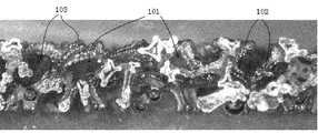
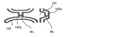
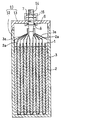
- FIG. 1 It is an optical microscope photograph of the section in the thickness direction of the aluminum porous body concerning one embodiment of the present invention. It is a cross-sectional schematic diagram of the aluminum porous body of FIG. 1 is a longitudinal sectional view schematically showing an electricity storage device according to an embodiment of the present invention.
- One embodiment of the present invention is (1) an aluminum porous body having a three-dimensional network skeleton in which a plurality of fiber parts including aluminum or an aluminum alloy are three-dimensionally connected, and the mass per unit volume is 30 to 1100 mg / cm 3 , the number F t of fiber portions per unit length in the thickness direction in the cross section in the thickness direction of the porous aluminum body, and the unit length in the surface direction on the surface of the porous aluminum body
- the ratio F t / F p with respect to the number F p of fiber portions per thickness relates to a porous aluminum body having a ratio of 1.4 or more.
- the conventional metal porous body having a three-dimensional network structure it is possible to reduce the weight by increasing the porosity and / or to fill a large amount of the electrode mixture or the catalyst composition. An effect is obtained.
- the porosity of the metal porous body is increased, the mass ratio of the metal contained in the metal porous body is decreased, so that the conductivity is easily lowered. Therefore, depending on the application, a decrease in conductivity may be a problem.
- the electrode is obtained by filling the metal porous body with an electrode mixture and then compressing the metal porous body in the thickness direction. It is done.
- the metal porous body is compressed after filling the electrode mixture into the metal porous body, it is difficult to increase the compression rate. If the compression ratio is low, the density of the part that forms the skeleton of the three-dimensional network structure of the metal porous body, that is, the fiber part (or rod-like part) cannot be increased, and it is difficult to be close to each other. Hateful.
- the mass (or apparent density) per unit volume is 30 to 1100 mg / cm 3 , and the ratio F t / F p is 1.4 or more. To do. With such a configuration, since the fiber parts forming the skeleton of the porous aluminum body can be brought close to each other, the conductivity can be increased.
- the aluminum porous body has a shape of a porous sheet having a predetermined thickness.
- the aluminum porous body is filled from the surface (specifically, one or both main surfaces) of the aluminum porous body.
- the surface (and the surface direction of the aluminum porous body) has a large distance between the fiber parts, and therefore it is easy to fill the electrode mixture or the catalyst composition. Accordingly, even when the apparent density of the porous aluminum body is high, the electrode mixture or the catalyst composition can be filled more uniformly.
- the three-dimensional network skeleton has a fiber part (or rod-like part) formed of aluminum or an aluminum alloy, or a skeleton in which the fiber parts are connected three-dimensionally to form a network. Refers to the structure.
- Number F t of the fiber portion in the thickness direction of the cross section of the porous aluminum, a predetermined length (e.g., 0.1 mm) when drawn a line segment having a parallel to the thickness direction, the fibrous portion intersecting the segment This means that the number is converted per unit length (for example, 1 mm).
- the number of fiber portions F p is a fiber that intersects a line segment having a predetermined length (for example, 0.1 mm) on the surface of the aluminum porous body in parallel with the surface direction of the aluminum porous body. This means that the number of parts is converted per unit length (for example, 1 mm).
- the fiber portions of the aluminum porous body are more densely distributed in the thickness direction than in the plane direction.
- the number of fiber parts can be measured using, for example, a cross section in the thickness direction of the porous aluminum body or an optical micrograph of the surface.
- the surface of the aluminum porous body refers to one main surface of the porous sheet in the aluminum porous body having the shape of the porous sheet having a predetermined thickness.
- the skeleton of the porous aluminum body is hollow.
- Such an aluminum porous body is advantageous because it is lightweight. Since the hollow skeleton of the porous aluminum body has a tunnel shape or a tube shape, when it is used for producing an electrode of an electricity storage device, the electrolyte is more easily distributed in the electricity storage device.
- the ratio F t / F p is preferably 1.4 to 10. When the ratio F t / F p is in such a range, the conductivity can be further enhanced while ensuring high filling properties.
- the number F t of the fiber unit is preferably 2 to 50 lines / mm. When Ft is in such a range, it is easy to improve conductivity while ensuring high filling properties.
- the porous aluminum body preferably has a thickness of 0.1 to 0.65 mm.
- the conductivity can be further increased.
- the aluminum porous body as an electrode current collector is filled with an electrode mixture containing a first electrode active material, and compressed in the thickness direction of the aluminum porous body. It relates to an electrode for an electricity storage device formed by the above.
- the porous aluminum body has high conductivity because the fiber parts are close to each other before filling the electrode mixture. After filling the electrode mixture, the conductivity of the obtained electrode can be further increased by further compressing the porous aluminum body. By increasing the conductivity of the electrode, the power storage device can have high output. Moreover, since the distance between fiber parts is large in the surface direction compared to the thickness direction of the aluminum porous body, it is easy to uniformly fill the electrode mixture.
- Still another embodiment of the present invention includes (7) a first electrode, a second electrode having a polarity opposite to that of the first electrode, a separator interposed between the first electrode and the second electrode, and
- the electrical storage device contains an electrolyte, at least the first electrode is the electrode described in (6) above, and the second electrode contains a second electrode active material.
- the electricity storage device is a lithium ion capacitor
- the electrolyte contains lithium ions and anions
- the first electrode active material is made of a material that reversibly carries at least the anions.
- the second electrode active material includes a material that reversibly carries the lithium ions.
- the electricity storage device is an electric double layer capacitor (EDLC)
- the electrolyte includes a cation and an anion
- the first electrode active material is at least
- the second electrode active material includes a material that reversibly supports the anion
- the second electrode active material includes a material that reversibly supports the cation.
- the power storage device is EDLC
- the electrolyte includes a cation and an anion
- the first electrode active material includes a material that reversibly supports the cation
- the second electrode active It is also preferable that the substance includes at least a material that reversibly carries the anion.
- a high-power EDLC can be obtained by using the electrode as at least the first electrode.
- the electricity storage device is a non-aqueous electrolyte secondary battery
- the electrolyte includes an alkali metal ion and an anion
- the first electrode active material is the alkali metal ion
- the second electrode active material includes a material that reversibly supports the alkali metal ions.
- the aluminum porous body contains aluminum or an aluminum alloy.
- the aluminum content in the aluminum porous body is, for example, 80% by mass or more, preferably 90% by mass or more, and more preferably 95% by mass or more or 98% by mass or more.
- the aluminum content in the aluminum porous body is 100% by mass or less, and may be 99.9% by mass or less. These lower limit values and upper limit values can be arbitrarily combined.
- the aluminum content in the aluminum porous body may be, for example, 80 to 100% by mass, or 95 to 100% by mass.
- the aluminum porous body may contain impurities inevitably mixed.
- Examples of the aluminum alloy contained in the porous aluminum body include an aluminum-iron alloy, an aluminum-copper alloy, an aluminum-manganese alloy, an aluminum-silicon alloy, an aluminum-magnesium alloy, an aluminum-magnesium-silicon alloy, an aluminum-zinc alloy, Examples include aluminum-nickel alloys.
- the aluminum porous body includes a plurality of fiber parts (or rod-like parts).
- the plurality of fiber portions are three-dimensionally connected to form a three-dimensional network skeleton.
- the three-dimensional network skeleton of the porous aluminum body has a cavity inside (that is, is hollow). Since the cavity in the skeleton of the aluminum porous body has a communication hole shape, the skeleton of the aluminum porous body has a tunnel shape or a tube shape.
- a porous aluminum body having a hollow skeleton is extremely lightweight while having a bulky three-dimensional structure.
- the apparent density of the aluminum porous body is 30 mg / cm 3 or more, preferably 50 mg / cm 3 or more, or 100 mg / cm 3 or more, more preferably 150 mg / cm 3 or more, or 175 mg / cm 3 or more.
- the apparent density of the aluminum porous body is 1100 mg / cm 3 or less, preferably 1000 mg / cm 3 or less, more preferably 700 mg / cm 3 or less. These lower limit values and upper limit values can be arbitrarily combined.
- the apparent density of the aluminum porous body may be, for example, 30 to 1100 mg / cm 3 , 50 to 1000 mg / cm 3, or 150 to 1000 mg / cm 3 .
- the porosity (or porosity) of the aluminum porous body is 50% by volume or more, preferably 55% by volume or more, and more preferably 60% by volume or more.
- the porosity is less than 100% by volume, preferably 99.5% by volume or less, more preferably 99% by volume or less. These lower limit values and upper limit values can be arbitrarily combined.
- the porosity may be, for example, 50 volume% or more and less than 100 volume%, 50 to 99 volume%, or 60 to 99 volume%.
- Ratio F t of the number F t of fiber parts per unit length in the thickness direction in the cross section in the thickness direction of the porous aluminum body and the number F p of fiber parts per unit length in the surface direction on the surface of the aluminum porous body / Fp is 1.4 or more, preferably 1.6 or more, more preferably 1.9 or more, or 2.3 or more.
- the ratio F t / F p is, for example, 10 or less, preferably 9 or less, more preferably 8 or less or 6 or less. These lower limit values and upper limit values can be arbitrarily combined.
- the ratio F t / F p may be, for example, 1.4 to 10, 1.6 to 9, or 1.9 to 8.
- the aluminum porous body according to the embodiment of the present invention has a high apparent density while having a somewhat high porosity.
- the porosity is high, the distance between the fiber portions of the aluminum porous body tends to be large, and the conductivity is likely to decrease.
- the mass ratio of aluminum or aluminum alloy in the aluminum porous body can be increased, so that the conductivity of the aluminum porous body can be increased.
- these components cannot be filled sufficiently.
- the ratio F t / F p of the number of fiber parts to the above values, even in applications such as filling an electrode mixture or a catalyst composition, A decrease in filling property can be suppressed.
- the ratio F t / F p is in the above range, when the electrode mixture is filled, the distance between the electrode active material particles contained in the electrode mixture and the fiber portion can be easily reduced. Therefore, even in such applications, the conductivity can be effectively increased, and the output of the electrode obtained using the aluminum porous body can be improved.
- the number F t of fiber parts is, for example, 2 to 50 / mm, preferably 2.5 to 45 / mm or 3 to 40 / mm, more preferably 5 to 30 / mm or 6 to 25 / mm. mm.
- the number F t of fiber parts is, for example, 2 to 50 / mm, preferably 2.5 to 45 / mm or 3 to 40 / mm, more preferably 5 to 30 / mm or 6 to 25 / mm. mm.
- the thickness of the aluminum porous body is, for example, 0.65 mm or less, preferably 0.63 mm or less, and more preferably 0.62 mm or less.
- the thickness of the aluminum porous body is, for example, 0.10 mm or more, preferably 0.13 mm or more. These lower limit values and upper limit values can be arbitrarily combined.
- the thickness of the aluminum porous body may be, for example, 0.10 to 0.65 mm or 0.13 to 0.62 mm. When the thickness of the porous aluminum body is in such a range, it is more advantageous in increasing the conductivity.
- the aluminum porous body can be formed, for example, by coating a resin porous body having continuous voids with a metal (specifically, aluminum and / or an aluminum alloy). After coating with a metal, it may be compressed in the thickness direction as necessary.
- the mass per unit volume, porosity, ratio F t / F p, etc. of the aluminum porous body can be adjusted by controlling the structure of the resin porous body and / or the degree of compression after coating. From the viewpoint of easily controlling the ratio F t / F p , it is preferable to use compression in the thickness direction.
- the coating with metal can be performed by, for example, plating, vapor phase method (evaporation, plasma chemical vapor deposition, sputtering, etc.), application of metal paste, or the like.
- a three-dimensional network skeleton is formed by coating with metal. Of these coating methods, plating is preferred.
- the plating treatment it is only necessary to form a layer of aluminum or an aluminum alloy on the surface of the resin porous body (including the surface in the continuous void), and a known plating treatment method such as an electrolytic plating method, a molten salt plating method, etc. Can be adopted. By the plating process, a three-dimensional mesh-like aluminum porous body corresponding to the shape of the resin porous body is formed.
- a conductive layer prior to electrolytic plating.
- the conductive layer may be formed on the surface of the resin porous body by electroless plating, vapor deposition, sputtering, or by applying a conductive agent.
- the resin porous body is immersed in a dispersion containing the conductive agent. May be formed.
- the resin porous body is not particularly limited as long as it has continuous voids, and a resin foam, a resin nonwoven fabric, or the like can be used.
- a resin foam, a resin nonwoven fabric, or the like As the resin constituting these porous bodies, those capable of making the inside of the skeleton hollow by decomposition or dissolution while maintaining the shape of the metal three-dimensional network skeleton after the metal coating treatment are preferable.
- the resin in the skeleton is desirably decomposed or dissolved and removed by heat treatment or the like. After the heat treatment, components (resin, decomposition product, unreacted monomer, additive contained in the resin, etc.) remaining in the skeleton may be removed by washing or the like.
- the resin may be removed by performing a heat treatment while appropriately applying a voltage as necessary.
- this heat treatment may be performed while applying a voltage in a state where the plated porous body is immersed in a molten salt plating bath.
- a cavity such as a communication hole-like cavity
- the metal porous body that is, the aluminum porous body
- thermosetting resins such as thermosetting polyurethane and melamine resin
- thermoplastic resins such as olefin resin (polyethylene, polypropylene and the like) and thermoplastic polyurethane.
- resin foam depending on the type of resin and / or the method of producing the foam, each pore formed inside the foam becomes a cellular shape, and these are connected in series, and continuous voids. Is formed.
- a current collector using a resin foam.
- thermosetting polyurethane etc. from a viewpoint that a void
- the porous metal body thus obtained has a three-dimensional network structure skeleton corresponding to the shape of the resin foam.
- each porous aluminum body has a large number of cell-like pores, and has continuous voids (that is, communication holes) in which these cell-like pores communicate with each other.
- an opening (or window) is formed between the adjacent cell-shaped holes and the openings are in communication with each other.
- the shape of the opening (or window) is not particularly limited, and is, for example, a substantially polygonal shape (such as a substantially triangular shape, a substantially square shape, a substantially pentagonal shape, and / or a substantially hexagonal shape).
- the substantially polygonal shape is used in the meaning including a polygon and a shape similar to the polygon (for example, a shape in which the corners of the polygon are rounded or a shape in which the sides of the polygon are curved).
- the metal porous body can be compressed in the thickness direction after the metal coating process or after the metal coating process is performed to remove the internal resin.
- the degree of compression can be adjusted so that the apparent density, porosity, and ratio F t / F p of the aluminum porous body after compression are in the above ranges.
- FIG. 1 shows an optical micrograph of a cross section in the thickness direction of a porous aluminum body according to an embodiment of the present invention.
- the porous aluminum body has a plurality of fiber portions 102, and the fiber portions 102 form a cell-like pore 101 and are three-dimensionally connected to form a three-dimensional network skeleton.
- This skeleton has a plurality of cellular holes 101 surrounded by connected fiber portions 102, and a substantially polygonal opening (or window) 103 is formed between adjacent holes 101.
- the adjacent air holes 101 communicate with each other through the opening 103, whereby the aluminum porous body has continuous voids.
- the fiber portion 102 includes aluminum or an aluminum alloy.
- FIG. 2 is a cross-sectional view schematically showing a part of the porous aluminum body of FIG.
- the aluminum porous body has a plurality of fiber portions 102 and cell-like pores 101 surrounded by the plurality of fiber portions 102.
- An opening (not shown) is formed between the adjacent holes 101, and the adjacent holes communicate with each other to form a continuous gap.
- Porous aluminum skeleton i.e., fiber section 102 that forms a skeleton
- W f width
- the average pore diameter of the three-dimensional network skeleton (average diameter of cellular pores communicating with each other) is, for example, 50 to 1000 ⁇ m, preferably 100 to 100 ⁇ m.
- the thickness is 900 ⁇ m, more preferably 350 to 900 ⁇ m.
- the average pore diameter is preferably smaller than the thickness of the aluminum porous body before compression.
- Aluminum porous body has a large specific surface area. Therefore, when an aluminum porous body is used as a carrier, a large amount of a support (electrode mixture, catalyst composition, etc.) can be attached to a wide area of the surface of the aluminum porous body including the surface in the voids of the aluminum porous body. Moreover, since the contact area between the porous aluminum body and the support is large and a high porosity can be maintained while the support is filled in the voids, it is easy to increase the utilization rate of the support.
- a support electrode mixture, catalyst composition, etc.
- the conductivity of the electrode is usually increased by adding a conductive additive to the electrode mixture, but by using the aluminum porous body as described above, Even if the addition amount of the conductive assistant is reduced, it is easy to ensure high conductivity. Therefore, when it uses for an electrode, an output and / or energy density (and capacity
- the specific surface area of the porous aluminum is, for example, 100 ⁇ 700cm 2 / g, preferably 150 ⁇ 650cm 2 / g, more preferably 200 ⁇ 600cm 2 / g.
- the width of the cavity inside the skeleton of the porous aluminum body before compression (specifically, the width W f of the cavity in FIG. 2) is an average value, for example, 0.5 to 5 ⁇ m, preferably 1 to 4 ⁇ m, or 2 to 3 ⁇ m.
- an electrode is formed by compressing in the thickness direction after filling the electrode mixture with the aluminum mixture.
- the skeleton of the porous aluminum body is slightly crushed in the thickness direction, and the cavities in the skeleton are also crushed.
- the electrolyte can circulate through the cavity in the skeleton in the electricity storage device.
- the porous aluminum body according to the embodiment of the present invention has a high porosity and a bulky three-dimensional network skeleton, the fiber parts forming the skeleton are close to each other in the thickness direction.
- High conductivity Such a porous aluminum body can be used in various applications such as filters, various carriers or substrates, and current collectors for power storage devices, using its special structure. In particular, it is useful in applications where high conductivity is required, such as current collectors for power storage devices.
- the above-mentioned aluminum porous body according to the embodiment of the present invention assumes a state where no electrode active material is attached. That is, the aluminum porous body can be used as an electrode current collector in the electrode of the electricity storage device, but preferably has the above-described characteristics before the electrode active material is attached.
- An electrode for an electricity storage device is formed by filling the aluminum porous body as an electrode current collector with an electrode mixture and further compressing (or rolling) the aluminum porous body in the thickness direction. The Due to the compression, the apparent density, porosity, ratio F t / F p , average pore diameter, etc. of the current collector in the electrode change as compared with those of the aluminum porous body.
- the aluminum porous body is further compressed in the thickness direction in addition to the three-dimensional network of porous aluminum bodies.
- the fiber parts of the aluminum porous body are closer to each other, and the distance between the fiber part and the electrode active material particles is further reduced. Therefore, the electrode has high conductivity.
- the electrolyte can be sufficiently retained in the vicinity of the electrode active material. By using such an electrode, the output of the electricity storage device can be increased.
- the electrode mixture is usually used in the form of a slurry containing the components of the electrode mixture (electrode active material, conductive additive, binder, etc.).
- the electrode mixture slurry is obtained by dispersing the components of the electrode mixture in a dispersion medium.
- the dispersion medium for example, water or the like is used in addition to an organic solvent such as N-methyl-2-pyrrolidone (NMP).
- NMP N-methyl-2-pyrrolidone
- the dispersion medium is removed by drying during the manufacturing process of the electrode (for example, after the slurry is filled in the current collector and / or after rolling).
- the electrode mixture can be filled in the aluminum porous body by a known method.
- the electrode mixture includes an electrode active material as an essential component, and can include a conductive additive and / or a binder as an optional component.
- the conductivity of the electrode can be further improved.
- a binder in the electrode mixture, the space between the electrode active material particles, between the electrode active material particles and the conductive auxiliary agent, and between the electrode active material particles or the conductive auxiliary agent and the current collector are further strengthened. Can be bound.
- the electrode active material can be appropriately selected according to the polarity of the electrode, the type of the electricity storage device, and the like.
- the electricity storage device includes a first electrode, a second electrode having a polarity opposite to that of the first electrode, a separator interposed therebetween, and an electrolyte, and at least the first electrode is used as the first electrode.
- a well-known thing can be used as a 2nd electrode according to the kind of electrical storage device, you may use said electrode.
- the second electrode includes a second electrode active material.
- the power storage device is not particularly limited as long as an aluminum current collector can be used.
- a capacitor such as a lithium ion capacitor or EDLC; a nonaqueous electrolyte such as a lithium ion secondary battery or a sodium ion secondary battery A secondary battery etc. can be illustrated.
- the separator included in the electricity storage device can be appropriately selected according to the type of the electricity storage device.
- the separator has ion permeability and is interposed between the first electrode and the second electrode, and physically separates them to prevent a short circuit.
- the separator has a porous structure and allows ions to pass through by holding an electrolyte in the pores.
- a material of the separator for example, polyolefin such as polyethylene and polypropylene; polyester such as polyethylene terephthalate; polyamide; polyimide; cellulose; glass fiber and the like can be used.
- the average pore diameter of the separator is not particularly limited and is, for example, about 0.01 to 5 ⁇ m.
- the thickness of the separator is not particularly limited, and is about 10 to 100 ⁇ m, for example.
- the configuration of the electrode and the electricity storage device will be described in more detail by taking a lithium ion capacitor, an EDLC, and a nonaqueous electrolyte secondary battery as examples.
- the first electrode is a positive electrode.
- the electrode according to the embodiment of the present invention is used as a positive electrode.
- the first electrode active material (that is, the positive electrode active material) contained in the positive electrode that is the first electrode includes at least a material that reversibly carries an anion.
- the positive electrode active material may include a material that reversibly supports anions and cations.
- the positive electrode active material reversibly carry anions and lithium ions.
- Materials that reversibly carry anions (and cations) include materials that adsorb and desorb anions (and cations) and materials that occlude and release (or insert and desorb) anions (and cations). .
- the former is a material that causes a non-Faraday reaction during charging and discharging
- the latter is a material that causes a Faraday reaction during charging and discharging.
- porous carbon materials such as activated carbon, nanoporous carbon, mesoporous carbon, microporous carbon, and carbon nanotube.
- the first porous carbon material may be activated or may not be activated.
- These 1st porous carbon materials can be used individually by 1 type or in combination of 2 or more types.
- activated carbon, nanoporous carbon, and the like are preferable. Note that porous carbon having fine pores on the order of sub nm to sub ⁇ m is referred to as nanoporous carbon.
- the first electrode active material can further contain other active materials as required in addition to the first porous carbon material.
- the content of the first porous carbon material in the first electrode active material is preferably more than 50% by mass, and may be 80% by mass or more or 90% by mass or more.
- the content of the first porous carbon material in the first electrode active material is 100% by mass or less.
- the content of activated carbon and nanoporous carbon in the first electrode active material is preferably in such a range. It is also preferable that the first electrode active material contains only the first porous carbon material (particularly activated carbon and / or nanoporous carbon).
- nanoporous carbon known ones used for lithium ion capacitors can be used, for example, those obtained by heating metal carbides such as silicon carbide and titanium carbide in an atmosphere containing chlorine gas. Also good.
- the activated carbon known ones used for lithium ion capacitors can be used.
- the raw material of activated carbon include wood; coconut shells; pulp waste liquid; coal or coal-based pitch obtained by thermal decomposition thereof; heavy oil or petroleum-based pitch obtained by thermal decomposition thereof; phenol resin and the like.
- the carbonized material is generally then activated.
- the activation method include a gas activation method and a chemical activation method.
- the average particle diameter of the activated carbon is not particularly limited, but is preferably 20 ⁇ m or less.
- the specific surface area is not particularly limited, but is preferably about 800 to 3000 m 2 / g. When the specific surface area is in such a range, it is advantageous for increasing the capacitance of the lithium ion capacitor, and the internal resistance can be reduced.
- the type of the conductive auxiliary agent is not particularly limited, and carbon black such as acetylene black and ketjen black; graphite (natural graphite such as flake graphite and earthy graphite; artificial graphite and the like); conductive compound such as ruthenium oxide A conductive fiber such as carbon fiber and metal fiber.
- the amount of the conductive assistant is, for example, 0 to 30 parts by mass, preferably 0 to 20 parts by mass with respect to 100 parts by mass of the first electrode active material. When the amount of the conductive auxiliary is within such a range, it is easy to increase the density of the electrode active material while ensuring the conductivity of the electrode mixture.
- the amount of the conductive auxiliary is 5 parts by mass or less (for example, 0 to 5 parts by mass), or 3 parts by mass or less (for example, 0 to 3 parts by mass) with respect to 100 parts by mass of the first electrode active material. You can also
- the type of the binder is not particularly limited.
- a fluorine resin such as polyvinylidene fluoride (PVDF) or polytetrafluoroethylene
- a chlorine-containing vinyl resin such as polyvinyl chloride
- a polyolefin resin such as polyethylene
- a rubbery heavy material such as styrene butadiene rubber.
- Polyvinyl pyrrolidone polyvinyl alcohol
- cellulose derivatives [cellulose ethers such as carboxymethyl cellulose (carboxyalkyl cellulose and the like)] and the like can be used.
- the amount of the binder is not particularly limited, and can be selected from the range of, for example, about 0.5 to 15 parts by mass, preferably 1 to 12 parts by mass, more preferably 1 to 10 parts per 100 parts by mass of the first electrode active material. A mass part may be sufficient. In the embodiment of the present invention, since a three-dimensional network current collector is used, even if the amount of the binder is small, a large amount of electrode mixture can be held on the current collector.
- the amount of the binder can be 5 parts by mass or less (for example, 1 to 5 parts by mass) with respect to 100 parts by mass of the first electrode active material, and may be 2 to 4 parts by mass.
- the thickness of the positive electrode can be appropriately selected from the range of 50 to 2000 ⁇ m, for example.
- the negative electrode that is the second electrode includes a second electrode active material (that is, a negative electrode active material) and can include a second electrode current collector (that is, a negative electrode current collector) that holds the second electrode active material.
- the negative electrode current collector may be a metal foil, but is preferably a metal porous body from the viewpoint of increasing the capacity of the lithium ion capacitor.
- the porous metal body may have an aluminum porous body or a three-dimensional network skeleton (particularly, a hollow skeleton) similar to the state before the aluminum porous body is compressed.
- the material for the negative electrode current collector is preferably copper, copper alloy, nickel, nickel alloy, stainless steel, or the like.
- the negative electrode current collector can be produced according to the case of an aluminum porous body using these materials instead of aluminum or an aluminum alloy when the resin porous body is metal-coated.
- the obtained metal porous body may be compressed as in the case of the aluminum porous body, or may be used as a negative electrode current collector without being compressed.
- the negative electrode active material includes a material that reversibly carries lithium ions (specifically, occlusion and release, or insertion and desorption).
- materials that cause a Faraday reaction during charge and discharge for example, a carbon material that absorbs and releases lithium ions (also referred to as a second carbon material), and lithium titanium oxide (such as lithium titanate). Spinel type lithium titanium oxide etc.), silicon oxide, silicon alloy, tin oxide and tin alloy.
- the second carbon material include graphitizable carbon (soft carbon), non-graphitizable carbon (hard carbon), graphite (carbon materials having a graphite-type crystal structure such as artificial graphite and natural graphite), and the like. .
- a negative electrode active material may be used individually by 1 type, and may be used in combination of 2 or more type.
- the negative electrode active material preferably has a theoretical capacity of 300 mAh / g or more.
- the second carbon material is preferable, and graphite and / or hard carbon is particularly preferable.
- the content of the second carbon material in the negative electrode active material is preferably more than 50% by mass, and may be 80% by mass or more or 90% by mass or more. Content of the 2nd carbon material in a negative electrode active material is 100 mass% or less. In particular, the content of graphite and / or hard carbon in the negative electrode active material is preferably within such a range. It is also preferable that the negative electrode active material contains only the second carbon material (particularly graphite and / or hard carbon).
- the negative electrode active material is preferably doped with lithium in advance (hereinafter referred to as pre-doping). This increases the voltage of the capacitor, which is further advantageous for increasing the capacity of the lithium ion capacitor. Note that the negative electrode capacity is preferably larger than the positive electrode capacity in order to suppress lithium deposition.
- Lithium doping can be performed by a known method.
- the doping of lithium may be performed when the capacitor is assembled.
- lithium metal foil is housed in a capacitor container together with a positive electrode, a negative electrode, and an electrolyte, and the assembled capacitor is kept warm in a constant temperature room at around 60 ° C., thereby elution of lithium ions from the lithium metal foil and The material can be doped.
- the negative electrode is, for example, coated or filled with a negative electrode mixture slurry containing a negative electrode active material on a negative electrode current collector, and then the dispersion medium contained in the negative electrode mixture slurry is removed, and further, if necessary, the negative electrode active material It can be obtained by compressing (or rolling) the current collector holding the. Moreover, as a negative electrode, you may use what is obtained by forming the deposit film of a negative electrode active material on the surface of a negative electrode collector by vapor phase methods, such as vapor deposition and sputtering.
- the negative electrode mixture slurry may contain a binder, a conductive aid and the like in addition to the negative electrode active material.
- a dispersion medium and a binder it can select suitably from what was illustrated about the electrode mixture of the 1st electrode.
- the amount of the binder with respect to 100 parts by mass of the negative electrode active material can be appropriately selected from the range of the amount of the binder with respect to 100 parts by mass of the first electrode active material.
- the conductive assistant is not particularly limited, and examples thereof include carbon black such as acetylene black and ketjen black; conductive compound such as ruthenium oxide; conductive fiber such as carbon fiber and metal fiber.
- the amount of the conductive auxiliary is, for example, 1 to 20 parts by mass, preferably 4 to 10 parts by mass with respect to 100 parts by mass of the negative electrode active material.
- the thickness of the negative electrode can be appropriately selected from the range of 50 to 2000 ⁇ m, for example.
- the thickness of the negative electrode is, for example, 100 to 2000 ⁇ m, preferably 200 to 1500 ⁇ m.
- the electrolyte includes cations and anions.
- the electrolyte of the lithium ion capacitor is preferably a non-aqueous electrolyte having lithium ion conductivity.
- a non-aqueous electrolyte contains lithium ions and anions.
- an electrolyte in which a salt (lithium salt) of lithium ions and anions is dissolved in a non-aqueous solvent (or an organic solvent), an ionic liquid containing lithium ions and anions, and the like are used.
- an ionic liquid is synonymous with the salt (molten salt) of a molten state, and is a liquid ionic substance comprised with an anion and a cation.
- the electrolyte can contain a nonaqueous solvent and / or an additive in addition to the ionic liquid, and the content of the ionic liquid in the electrolyte may be 60% by mass or more. Preferably, it is 80 mass% or more or 90 mass% or more.
- the concentration of the lithium salt or lithium ion in the electrolyte can be appropriately selected from the range of 0.3 to 5 mol / L, for example.
- the kind of the anion (first anion) constituting the lithium salt is not particularly limited.
- anion of fluorine-containing acid anion of fluorine-containing phosphate such as hexafluorophosphate ion (PF 6 ⁇ ); tetrafluoroboric acid Anion of fluorine-containing boric acid such as ion (BF 4 ⁇ )], anion of chlorine-containing acid [perchlorate ion (ClO 4 ⁇ ), etc.], anion of oxyacid having an oxalate group [bis (oxalato) borate ion Oxalatoborate ion such as (B (C 2 O 4 ) 2 ⁇ ); Oxalatophosphate ion such as tris (oxalato) phosphate ion (P (C 2 O 4 ) 3 ⁇ )], anion of fluoroalkanesulfonic acid [trifluoromethanesulfonate ion (CF 3 SO
- bissulfonylamide anion examples include bis (fluorosulfonyl) amide anion [bis (fluorosulfonyl) amide anion (N (SO 2 F) 2 ⁇ ) and the like], (fluorosulfonyl) (perfluoroalkylsulfonyl) amide Anion [(fluorosulfonyl) (trifluoromethylsulfonyl) amide anion ((FSO 2 ) (CF 3 SO 2 ) N ⁇ , etc.)], bis (perfluoroalkylsulfonyl) amide anion [bis (trifluoromethylsulfonyl) amide anion (N (SO 2 CF 3 ) 2 ⁇ ), bis (pentafluoroethylsulfonyl) amide anion (N (SO 2 C 2 F 5 ) 2 ⁇ ) and the like].
- the carbon number of the perfluoroalkyl group is preferably
- bis (fluorosulfonyl) amide anion FSA ⁇ : bis (fluorosulfonyl) amide anion
- bis (trifluoromethylsulfonyl) amide anion TFSA ⁇ : bis (trifluoromethylsulfonyl) amide anion
- bis ( A bis (perfluoroalkylsulfonyl) amide anion PFSA ⁇ : bis (perfluoroalkylsulfonyl) amide anion
- PFSA ⁇ bis (perfluoroalkylsulfonyl) amide anion
- the non-aqueous solvent contained in the electrolyte is not particularly limited, and known non-aqueous solvents used for lithium ion capacitors can be used.
- Non-aqueous solvents include, for example, cyclic carbonates such as ethylene carbonate, propylene carbonate, and butylene carbonate; chain carbonates such as dimethyl carbonate, diethyl carbonate, and ethyl methyl carbonate; cyclic carbonates such as ⁇ -butyrolactone. Etc. can be preferably used.
- a non-aqueous solvent may be used individually by 1 type, and may be used in combination of 2 or more type.
- the ionic liquid containing lithium ions contains lithium ions and anions (second anions).
- second anion various anions exemplified for the first anion, specifically, a bissulfonylamide anion, an anion of a fluorine-containing acid, an anion of a chlorine-containing acid, an anion of an oxyacid having an oxalate group, a fluoroalkanesulfonic acid Can be used.
- a 2nd anion can be used individually by 1 type or in combination of 2 or more types.
- the second anion preferably contains at least a bissulfonylamide anion.
- the content of the bissulfonylamide anion in the second anion is, for example, 80 to 100 mol%, preferably 90 to 100 mol%.
- the ionic liquid containing lithium ions may further contain a second cation in addition to the lithium ions (first cation).
- a second cation an inorganic cation other than lithium, for example, sodium ion, magnesium ion, calcium ion, ammonium cation or the like may be used, but an organic cation is preferable.
- a 2nd cation can be used individually by 1 type or in combination of 2 or more types.
- Examples of the organic cation used as the second cation include a cation derived from an aliphatic amine, an alicyclic amine, or an aromatic amine (for example, a quaternary ammonium cation), and a cation having a nitrogen-containing heterocycle ( That is, nitrogen-containing organic onium cations such as cations derived from cyclic amines; sulfur-containing onium cations; phosphorus-containing onium cations, and the like.
- nitrogen-containing organic onium cations those having pyrrolidine, pyridine, or imidazole as the nitrogen-containing heterocyclic skeleton are preferable.
- the quaternary ammonium cation include tetraalkylammonium cation, ethyltrimethylammonium cation, hexyltrimethylammonium cation, tetraethylammonium cation (TEA + : tetraethylammonium cation), and methyltriethylammonium cation (TEMA + : methyltriethylammonium cation).
- TAA + tetraethylammonium cation
- TEMA + methyltriethylammonium cation
- the organic onium cation having a pyrrolidine skeleton preferably has two alkyl groups on one nitrogen atom constituting the pyrrolidine ring.
- Examples of such organic onium cations include 1,1-dimethylpyrrolidinium cation, 1,1-diethylpyrrolidinium cation, 1-ethyl-1-methylpyrrolidinium cation, and 1-methyl-1-propyl.
- Pyrrolidinium cation (MPPY + : 1-methyl-1-pyrrolidinium cation), 1-butyl-1-methylpyrrolidinium cation (MBPY + : 1-butyl-1-methylpyrrolidinium cation), 1-ethyl-1-propyl Examples include pyrrolidinium cation.
- the organic onium cation having a pyridine skeleton preferably has one alkyl group on one nitrogen atom constituting the pyridine ring.
- Examples of such organic onium cations include 1-alkylpyridinium cations such as 1-methylpyridinium cation, 1-ethylpyridinium cation, and 1-propylpyridinium cation.
- the organic onium cation having an imidazole skeleton preferably has one alkyl group on each of two nitrogen atoms constituting the imidazole ring.
- organic onium cations include 1,3-dimethylimidazolium cation, 1-ethyl-3-methylimidazolium cation (EMI + : 1-ethyl-3-methylimidazolium cation), 1-methyl-3- Propylimidazolium cation, 1-butyl-3-methylimidazolium cation (BMI + : 1-butyl-3-methylimidazolium cation), 1-ethyl-3-propylimidazolium cation, 1-butyl-3-ethylimidazolium cation Etc.
- imidazolium cations having a methyl group and an alkyl group having 2 to 4 carbon atoms such as EMI + and BMI + are preferable.
- the 1st electrode active material (or positive electrode active material) contained in a positive electrode contains the material which carry
- the first electrode active material preferably includes a material that reversibly supports anions and cations.
- a porous carbon material (third porous carbon material) is preferable as the material that reversibly supports at least anions.
- the second electrode active material (or negative electrode active material) included in the second electrode (or negative electrode) includes a material (for example, a porous carbon material (fourth porous carbon material)) that reversibly supports cations.
- the first electrode active material (or negative electrode active material) included in the negative electrode includes a material (for example, a porous carbon material (fifth porous carbon material)) that reversibly supports cations, and the second electrode active material ( Alternatively, the positive electrode active material) includes at least a material that reversibly supports an anion.
- the second electrode active material may include a material that reversibly carries anions and cations. As such a material, a porous carbon material (sixth porous carbon material) is preferable.
- Examples of the material that reversibly supports cations and / or anions include materials that adsorb and desorb cations and / or anions, and materials that occlude and release (or insert and desorb) cations and / or anions. It can be illustrated.
- the former is a material that causes a non-Faraday reaction during charging and discharging
- the latter is a material that causes a Faraday reaction during charging and discharging.
- the porous carbon materials exemplified as the first porous carbon material of the lithium ion capacitor can be used.
- the porous carbon materials activated carbon, nanoporous carbon, and the like are preferable.
- the third porous carbon material and the fourth porous carbon material may be the same or different.
- the fifth porous carbon material and the sixth porous carbon material may be the same or different.
- Each of the positive electrode active material and the negative electrode active material can further contain other active materials as necessary in addition to the porous carbon material.
- Content of the said porous carbon material in a positive electrode active material or a negative electrode active material can be suitably selected from the range similar to content of the porous carbon material in the 1st electrode active material described about the lithium ion capacitor.
- the types of the conductive auxiliary agent and binder and the amounts of these components relative to the electrode active material can also be appropriately selected from the ranges described for the first electrode of the lithium ion capacitor.
- the second electrode can be produced according to the case of the positive electrode of the lithium ion capacitor.
- the thickness of the second electrode can be selected from the same range as the positive electrode of the lithium ion capacitor.
- the electrolyte used for EDLC may contain water or a non-aqueous electrolyte.
- the electrolyte includes a cation and an anion.
- As an electrolyte in addition to an electrolyte in which a salt of a cation (third cation) and an anion (third anion) is dissolved in a non-aqueous solvent (or an organic solvent), a cation (fourth cation) and an anion (fourth anion)
- a non-aqueous electrolyte such as an ionic liquid containing is preferably used.
- the concentration of the cation in the electrolyte can be appropriately selected from the range of 0.3 to 5 mol / L, for example.
- Examples of the third cation include inorganic cations such as lithium ion, sodium ion, magnesium ion, calcium ion, and ammonium cation; and the same organic cation exemplified as the second cation of the lithium ion capacitor.
- the third cation may contain one kind of cation or may contain two or more kinds of anions.
- the third cation preferably contains at least an organic cation. Of the organic cations, quaternary ammonium cations such as TEA + and TEMA + are preferable.
- the third anion can be appropriately selected from those exemplified as the first anion of the lithium ion capacitor.
- the third anion may include one kind of anion or two or more kinds of anions.
- As a nonaqueous solvent it can select suitably from what was illustrated about the lithium ion capacitor.
- the fourth cation contained in the ionic liquid can be appropriately selected from those exemplified for the third cation.
- the fourth cation may contain one kind of cation or may contain two or more kinds of cations.
- the fourth cation preferably contains at least an organic cation.
- imidazolium cations such as EMI + and BMI + are preferred.
- the fourth anion contained in the ionic liquid can be appropriately selected from those exemplified as the second anion of the lithium ion capacitor.
- the fourth anion may include one kind of anion or two or more kinds of anions.
- the fourth anion preferably includes at least a bissulfonylamide anion.
- the content of the bissulfonylamide anion in the fourth anion can be selected from the same range as in the case of the second anion.
- Content of the ionic liquid in electrolyte can be suitably selected from the range illustrated about the lithium ion capacitor.
- the electrode according to the embodiment of the present invention may be used for the second electrode (negative electrode), but is preferably used for the first electrode (positive electrode).
- the first electrode active material (positive electrode active material) included in the first electrode (positive electrode) includes a material that reversibly carries (specifically, occludes and releases, or inserts and desorbs) alkali metal ions. . Such a material is a material that causes a Faraday reaction during charging and discharging.
- Such materials include metal chalcogen compounds (sulfides, oxides, etc.), alkali metal-containing transition metal oxides (lithium-containing transition metal oxides, sodium-containing transition metal oxides), alkali metal-containing transition metal phosphates. (Such as iron phosphate having an olivine structure). These materials can be used singly or in combination of two or more.
- the second electrode active material (negative electrode active material) included in the second electrode (negative electrode) includes a material that reversibly carries (specifically, occludes and releases) the alkali metal ions. Such a material is a material that causes a Faraday reaction during charging and discharging.
- the negative electrode active material include sodium titanium oxide (such as spinel sodium titanium oxide such as sodium titanate) in addition to those exemplified as the negative electrode active material of the lithium ion capacitor.
- a negative electrode active material can be suitably selected according to the kind of alkali metal ion.
- the negative electrode active material may be doped with alkali metal ions such as lithium according to the case of the lithium ion capacitor.
- the negative electrode as the second electrode includes a negative electrode active material and can include an electrode current collector (that is, a negative electrode current collector) that holds the negative electrode active material.
- an electrode current collector that is, a negative electrode current collector
- the same as the negative electrode current collector of the lithium ion capacitor can be used.
- the negative electrode can be produced according to the case of the negative electrode of a lithium ion capacitor.
- the thickness of the negative electrode can be selected from the same range as the negative electrode of the lithium ion capacitor.
- the electrode mixture (negative electrode mixture) used for the negative electrode can contain a conductive additive and / or a binder.
- a binder it can select suitably from what was illustrated about the positive electrode of the lithium ion capacitor.
- the conductive assistant include those exemplified for the negative electrode of the lithium ion capacitor, and nanocarbons such as carbon nanotubes.
- a conductive support agent can be used individually by 1 type or in combination of 2 or more types. The amounts of the conductive agent and the binder with respect to the negative electrode active material are the same as in the case of the lithium ion capacitor.
- the electrolyte used for the nonaqueous electrolyte secondary battery includes an alkali metal ion and an anion.
- a non-aqueous electrolyte can be used.
- an electrolyte in which a salt (alkali metal salt) of an alkali metal ion and an anion (fifth anion) is dissolved in a non-aqueous solvent (or an organic solvent) is used.
- an ionic liquid containing an alkali metal ion and an anion (sixth anion) is used.
- concentration of the alkali metal salt or alkali metal ion in the electrolyte can be appropriately selected from the range of 0.5 to 3 mol / L, for example.
- the alkali metal ion can be appropriately selected from lithium ion, sodium ion, potassium ion, rubidium ion, cesium ion, and the like according to the type of the nonaqueous electrolyte secondary battery.
- the electrolyte in a lithium ion secondary battery, the electrolyte includes lithium ions as alkali metal ions, and in a sodium ion secondary battery, the electrolyte includes sodium ions as alkali metal ions.
- the electrolyte may contain other alkali metal ions in addition to lithium ions and / or sodium ions.
- the fifth anion constituting the alkali metal salt can be appropriately selected from those exemplified as the first anion of the lithium ion capacitor.
- One alkali metal salt may be used alone, or two or more alkali metal salts having different types of fifth anions may be used in combination.
- As a nonaqueous solvent it can select suitably from what was illustrated about the lithium ion capacitor.
- the sixth anion contained in the ionic liquid can be appropriately selected from those exemplified as the second anion of the lithium ion capacitor.
- the sixth anion may include one kind of anion or two or more kinds of anions.
- the sixth anion preferably contains at least a bissulfonylamide anion.
- the content of the bissulfonylamide anion in the sixth anion can be selected from the same range as in the second anion.
- Content of the ionic liquid in electrolyte can be suitably selected from the range illustrated about the lithium ion capacitor.
- the power storage device includes, for example, (a) a step of forming an electrode group with a first electrode, a second electrode, and a separator interposed between the first electrode and the second electrode, and (b) an electrode group and an electrolyte. It can manufacture by passing through the process of accommodating in a cell case.
- FIG. 3 is a longitudinal sectional view schematically showing an electricity storage device according to an embodiment of the present invention.
- the power storage device includes a stacked electrode group, an electrolyte (not shown), and a rectangular aluminum case 10 for housing them.
- the case 10 includes a bottomed container body 12 having an upper opening and a lid 13 that closes the upper opening.
- an electrode group When assembling an electricity storage device, first, an electrode group is configured by laminating a positive electrode (first electrode) 2 and a negative electrode (second electrode) 3 with a separator 1 interposed between them. The electrode group thus formed is inserted into the container body 12 of the case 10. Thereafter, a step of injecting an electrolyte into the container body 12 and impregnating the electrolyte in the gaps of the separator 1, the positive electrode 2 and the negative electrode 3 constituting the electrode group is performed.
- the electrolyte includes an ionic liquid
- the electrode group may be impregnated in the electrolyte, and then the electrode group including the electrolyte may be accommodated in the container body 12.
- a safety valve 16 is provided for releasing gas generated inside when the internal pressure of the case 10 rises.
- An external positive terminal 14 that penetrates the lid 13 is provided near the one side of the lid 13 with the safety valve 16 in the center, and an external that penetrates the lid 13 is located near the other side of the lid 13.
- a negative terminal (not shown) is provided.
- the stacked electrode group is composed of a plurality of positive electrodes 2, a plurality of negative electrodes 3, and a plurality of separators 1 interposed therebetween, all in the form of a rectangular sheet.
- the separator 1 is formed in a bag shape so as to surround the positive electrode 2, but the form of the separator is not particularly limited.
- the plurality of positive electrodes 2 and the plurality of negative electrodes 3 are alternately arranged in the stacking direction within the electrode group.
- a positive electrode lead piece 2 a may be formed at one end of each positive electrode 2.
- the plurality of positive electrodes 2 are connected in parallel by bundling the positive electrode lead pieces 2 a of the plurality of positive electrodes 2 and connecting them to the external positive terminal 14 provided on the lid 13 of the case 10.
- a negative electrode lead piece 3 a may be formed at one end of each negative electrode 3.
- a plurality of negative electrodes 3 are connected in parallel by bundling the negative electrode lead pieces 3a of the plurality of negative electrodes 3 and connecting them to an external negative terminal provided on the lid 13 of the case 10.
- the bundle of the positive electrode lead pieces 2a and the bundle of the negative electrode lead pieces 3a are desirably arranged on the left and right sides of one end face of the electrode group with an interval so as to avoid mutual contact.
- the external positive terminal 14 and the external negative terminal are both columnar, and at least a portion exposed to the outside has a thread groove.
- a nut 7 is fitted in the screw groove of each terminal, and the nut 7 is fixed to the lid 13 by rotating the nut 7.
- a flange 8 is provided in a portion of each terminal accommodated in the case 10, and the flange 8 is fixed to the inner surface of the lid 13 through a washer 9 by the rotation of the nut 7.
- the electrode group is not limited to a laminated type, and may be formed by winding a positive electrode and a negative electrode through a separator.
- the dimension of the negative electrode may be made larger than that of the positive electrode from the viewpoint of preventing lithium from being deposited on the negative electrode.
- a plurality of fiber parts containing aluminum or an aluminum alloy is a porous aluminum body having a three-dimensionally linked three-dimensional network skeleton, and the mass per unit volume is 30 to 1100 mg / cm 3 , and the number F t of the fiber portions per unit length of the thickness direction in the thickness direction of the cross section of the aluminum porous body, and the number F p of the fiber portion of the per unit length in the plane direction at the surface of the porous aluminum
- the aluminum porous body has a ratio F t / F p of 1.4 or more.
- an aluminum porous body has high conductivity, when it is used as an electrode current collector of an electricity storage device, the output of the electrode and the electricity storage device can be increased.
- Appendix 2 The skeleton of the aluminum porous body of Appendix 1 is hollow, the mass per unit volume is 175 to 1000 mg / cm 3 , the porosity is 50 to 99% by volume, and the ratio F t / F p It is 1.9 to 10 and the number F t of the fiber unit is a 6 to 25 present / mm, preferably has a thickness of 0.10 ⁇ 0.65 mm.
- Such an aluminum porous body can further improve electrical conductivity.
- the foam having the conductive layer formed on the surface was immersed in a molten salt aluminum plating bath, and a direct current having a current density of 3.6 A / dm 2 was applied for 90 minutes to form an aluminum layer.
- the mass of the aluminum layer per apparent area of the foam was 150 g / m 2 .
- the molten salt aluminum plating bath contained 33 mol% 1-ethyl-3-methylimidazolium chloride and 67 mol% aluminum chloride, and the temperature was 40 ° C.
- the foam with the aluminum layer formed on the surface was immersed in a lithium chloride-potassium chloride eutectic molten salt at 500 ° C., and a negative potential of ⁇ 1 V was applied for 30 minutes to decompose the foam.
- the obtained aluminum porous body was taken out from the molten salt, cooled, washed with water, and dried. The dried product was further compressed in the thickness direction to obtain a porous aluminum body (a1).
- the obtained aluminum porous body (a1) has a three-dimensional network-like porous structure in which the pores communicate with each other, reflecting the pore shape of the foam, and the apparent density (mass per unit volume) is 210 mg. / Cm 3 , the porosity was 92% by volume, the average pore diameter was 400 ⁇ m, the specific surface area (BET specific surface area) by the BET method was 400 cm 2 / g, and the thickness was 0.6 mm. . Further, the three-dimensional network skeleton of the aluminum porous body had a communication hole-like cavity formed by removing the foam inside.
- a photomicrograph of one main surface of the aluminum porous body and a cross section in the thickness direction was taken, the number of fiber portions F t and F p per unit length was determined, and the ratio F t / F p was calculated. 6.
- the resistivity of the obtained aluminum porous body was measured as follows. The resistance was measured by a four-terminal method while pressing a test piece having a width of 1 cm against the terminal with a load of 100 g / cm 2 . The distance between the terminals was 3.3 cm.
- Examples 2 to 6 and Comparative Examples 1 to 3 The porous aluminum bodies (a2) to (a6) and (b1) were prepared in the same manner as in Example 1 except that the porosity, the number of cells, and the compression ratio when the dried product was compressed were appropriately adjusted. ) To (b3) were prepared, and the resistivity was measured. Table 1 shows the resistivity of the porous aluminum body together with the apparent density and porosity of the porous aluminum bodies of Examples 1 to 6 and Comparative Examples 1 to 3, along with the number F t of fibers and the ratio F t / F p .
- (A1) to (a6) are the aluminum porous bodies of Examples 1 to 6, respectively
- (b1) to (b3) are the aluminum porous bodies of Comparative Examples 1 to 3, respectively.
- the ratio F t / F p is less than 1.4 and 1.4 or more, the behavior of the resistivity is different, and the ratio F t / F p is 1.4 or more. It can be seen that the resistivity is particularly small. From the viewpoint of reducing the resistivity, the ratio F t / F p is more preferably 1.9 or more.
- Examples 7-12 and Comparative Examples 4-6 Using the aluminum porous bodies of Examples 1 to 6 and Comparative Examples 1 to 3 as current collectors, lithium ion capacitors were produced by the following procedure, and the output was evaluated.
- the obtained positive electrode mixture slurry was filled in a porous aluminum body using a die coater and dried at 100 ° C. for 30 minutes.
- the dried product was rolled using a pair of rolls to produce a positive electrode having a thickness of 160 ⁇ m.
- the foam with the Cu layer formed on the surface is heat-treated at 700 ° C. in an air atmosphere to decompose the foam, and then fired in a hydrogen atmosphere to reduce the oxide film formed on the surface.
- a copper porous body (negative electrode current collector) was obtained.
- the obtained negative electrode current collector has a three-dimensional network-like porous structure in which the pores communicate with each other, reflecting the pore shape of the foam, the porosity is 92% by volume, and the average pore diameter is 550 ⁇ m.
- the BET specific surface area was 200 cm 2 / g.
- the three-dimensional network copper skeleton had a communication hole-like cavity formed by removing the foam.
- the obtained negative electrode mixture slurry was filled into the current collector obtained in the step (a) using a die coater and dried at 100 ° C. for 30 minutes.
- the dried product was rolled using a pair of rolls to produce a negative electrode having a thickness of 120 ⁇ m.
- a single-cell electrode group was formed by laminating a positive electrode and a negative electrode with a cellulose separator (thickness: 60 ⁇ m) interposed between the positive electrode and the negative electrode. Further, a lithium separator is disposed on the negative electrode side of the electrode group with a polyolefin separator (a laminate of a polyethylene microporous membrane and a polypropylene microporous membrane), and the obtained laminate is made of an aluminum laminate sheet. It accommodated in the produced cell case.
- a nonaqueous electrolyte was injected into the cell case, and impregnated into the positive electrode, the negative electrode, and the separator.
- a solution in which LiPF 6 as a lithium salt was dissolved in a mixed solvent containing ethylene carbonate and diethyl carbonate at a mass ratio of 1: 1 so as to have a concentration of 1.0 mol / L was used.
- the cell case was sealed while reducing the pressure with a vacuum sealer.
- the negative electrode lead wire and the lithium electrode lead wire are connected to a power source outside the cell case, and charged with a current of 0.2 mA / cm 2 to a potential of 0 V with respect to metallic lithium.
- a lithium ion capacitor (A1) was produced by pre-doping. Then, it charged / discharged with the electric current of 1 mA / cm ⁇ 2 >, and the discharge capacity (initial capacity) at this time was measured.
- the discharge capacity was measured by the following procedure using the obtained lithium ion capacitor.
- the battery was charged to 3.8V at a current of 2C with respect to the initial capacity, and discharged at a current of 2C or 50C until the voltage reached 2.2V.
- the discharge capacity (mAh) at this time was determined.
- the discharge capacity when discharged at a current of 2 C was “discharge capacity A”, and the discharge capacity when discharged at a current of 50 C was “discharge capacity B”.
- the output characteristics of the lithium ion capacitor were evaluated.
- Table 2 shows the results of Examples and Comparative Examples.
- the lithium ion capacitors of Examples 7 to 12 using the aluminum porous bodies (a1) to (a6) were designated as (A1) to (A6), respectively, and the aluminum porous bodies (b1) to (b3) were used.
- the lithium ion capacitors of Comparative Examples 4 to 6 were designated as (B1) to (B3), respectively.
- the lithium ion capacitors (A1) to (A6) using the aluminum porous bodies (a1) to (a6) show output characteristics of 82% or more, and the aluminum porous bodies (b1) to (b3 High output characteristics were obtained as compared with lithium ion capacitors (B1) to (B3) using
- the porous aluminum body according to the embodiment of the present invention can be used for various applications such as filters, various carriers or substrates, and current collectors for power storage devices. Since the aluminum porous body has high conductivity, it is particularly useful in applications where high conductivity is required, such as a current collector of an electricity storage device.
Landscapes
- Engineering & Computer Science (AREA)
- Chemical & Material Sciences (AREA)
- Power Engineering (AREA)
- Materials Engineering (AREA)
- Microelectronics & Electronic Packaging (AREA)
- Chemical Kinetics & Catalysis (AREA)
- Electrochemistry (AREA)
- General Chemical & Material Sciences (AREA)
- Electric Double-Layer Capacitors Or The Like (AREA)
- Cell Electrode Carriers And Collectors (AREA)
Abstract
L'invention concerne un corps poreux d'aluminium dans lequel plusieurs parties fibres contenant de l'aluminium ou un alliage d'aluminium possèdent un squelette en réseau tridimensionnel relié en trois dimensions. Dans ce corps poreux d'aluminium, la masse par unité de volume est de 30 à 110 mg / cm3, et le rapport Ft / Fp entre le nombre (Ft) de fibres d'une partie fibres correspondant à l'unité de longueur dans le sens de l'épaisseur dans une section transversale dans le sens de l'épaisseur de ce corps poreux et le nombre (Fp) de fibres d'une partie fibres correspondant à l'unité de longueur en direction de surface de la surface du corps poreux d'aluminium est supérieur ou égal à 1,4.
Applications Claiming Priority (2)
| Application Number | Priority Date | Filing Date | Title |
|---|---|---|---|
| JP2014004190A JP2017041462A (ja) | 2014-01-14 | 2014-01-14 | アルミニウム多孔体、蓄電デバイス用電極および蓄電デバイス |
| JP2014-004190 | 2014-01-14 |
Publications (1)
| Publication Number | Publication Date |
|---|---|
| WO2015107965A1 true WO2015107965A1 (fr) | 2015-07-23 |
Family
ID=53542855
Family Applications (1)
| Application Number | Title | Priority Date | Filing Date |
|---|---|---|---|
| PCT/JP2015/050308 Ceased WO2015107965A1 (fr) | 2014-01-14 | 2015-01-08 | Corps poreux d'aluminium, électrode pour dispositif condensateur et dispositif condensateur associé |
Country Status (2)
| Country | Link |
|---|---|
| JP (1) | JP2017041462A (fr) |
| WO (1) | WO2015107965A1 (fr) |
Families Citing this family (2)
| Publication number | Priority date | Publication date | Assignee | Title |
|---|---|---|---|---|
| GB2562064A (en) * | 2017-05-02 | 2018-11-07 | Zapgo Ltd | Supercapacitor device |
| JP2024516898A (ja) * | 2021-05-11 | 2024-04-17 | マックス-プランク-ゲゼルシャフト ツア フェーデルンク デア ヴィッセンシャフテン エー.ファオ. | 電極及び電池 |
Citations (2)
| Publication number | Priority date | Publication date | Assignee | Title |
|---|---|---|---|---|
| JP2012256583A (ja) * | 2011-02-18 | 2012-12-27 | Sumitomo Electric Ind Ltd | 電気化学素子用電極の製造方法 |
| JP2012256582A (ja) * | 2011-02-18 | 2012-12-27 | Sumitomo Electric Ind Ltd | 電気化学素子用電極の製造方法 |
-
2014
- 2014-01-14 JP JP2014004190A patent/JP2017041462A/ja active Pending
-
2015
- 2015-01-08 WO PCT/JP2015/050308 patent/WO2015107965A1/fr not_active Ceased
Patent Citations (2)
| Publication number | Priority date | Publication date | Assignee | Title |
|---|---|---|---|---|
| JP2012256583A (ja) * | 2011-02-18 | 2012-12-27 | Sumitomo Electric Ind Ltd | 電気化学素子用電極の製造方法 |
| JP2012256582A (ja) * | 2011-02-18 | 2012-12-27 | Sumitomo Electric Ind Ltd | 電気化学素子用電極の製造方法 |
Also Published As
| Publication number | Publication date |
|---|---|
| JP2017041462A (ja) | 2017-02-23 |
Similar Documents
| Publication | Publication Date | Title |
|---|---|---|
| JPWO2015098903A1 (ja) | アルカリ金属イオンキャパシタ | |
| CN105340120A (zh) | 锂电池 | |
| JPWO2015105136A1 (ja) | リチウムイオンキャパシタ用正極およびそれを用いたリチウムイオンキャパシタ | |
| JP2015154003A (ja) | 蓄電デバイスおよび充放電システム | |
| WO2014007188A1 (fr) | Condensateur à ion lithium | |
| EP3073500A1 (fr) | Condensateur et son procédé de fabrication | |
| JP6260209B2 (ja) | アルカリ金属イオンキャパシタ、その製造方法および充放電方法 | |
| JP2015153700A (ja) | 蓄電デバイス | |
| JP2013143422A (ja) | リチウムイオンキャパシタ | |
| WO2015107965A1 (fr) | Corps poreux d'aluminium, électrode pour dispositif condensateur et dispositif condensateur associé | |
| WO2015107800A1 (fr) | Corps poreux de cuivre, électrode pour dispositif condensateur et dispositif condensateur associé | |
| JP2015095634A (ja) | 蓄電デバイスおよびその製造方法 | |
| EP3109877A1 (fr) | Condensateur et son procédé de charge et de décharge | |
| JP2015135947A (ja) | リチウムイオンキャパシタ | |
| JP2016164948A (ja) | キャパシタ用正極およびキャパシタの製造方法ならびにキャパシタ | |
| JP2016171239A (ja) | リチウムイオンキャパシタの製造方法およびリチウムイオンキャパシタ | |
| JP2015204437A (ja) | リチウムイオンキャパシタ | |
| JP2015115336A (ja) | キャパシタおよびその充放電方法 | |
| JP2016181603A (ja) | リチウムイオンキャパシタ | |
| JP2017098365A (ja) | リチウムイオンキャパシタおよびリチウムイオンキャパシタが装着された電子機器 | |
| JP2017098363A (ja) | リチウムイオンキャパシタおよびリチウムイオンキャパシタが装着された電子機器 |
Legal Events
| Date | Code | Title | Description |
|---|---|---|---|
| 121 | Ep: the epo has been informed by wipo that ep was designated in this application |
Ref document number: 15737849 Country of ref document: EP Kind code of ref document: A1 |
|
| NENP | Non-entry into the national phase |
Ref country code: DE |
|
| NENP | Non-entry into the national phase |
Ref country code: JP |
|
| 122 | Ep: pct application non-entry in european phase |
Ref document number: 15737849 Country of ref document: EP Kind code of ref document: A1 |