WO2015108031A1 - すべり軸受 - Google Patents
すべり軸受 Download PDFInfo
- Publication number
- WO2015108031A1 WO2015108031A1 PCT/JP2015/050659 JP2015050659W WO2015108031A1 WO 2015108031 A1 WO2015108031 A1 WO 2015108031A1 JP 2015050659 W JP2015050659 W JP 2015050659W WO 2015108031 A1 WO2015108031 A1 WO 2015108031A1
- Authority
- WO
- WIPO (PCT)
- Prior art keywords
- bearing
- resin
- overlay layer
- inner peripheral
- solid lubricant
- Prior art date
- Legal status (The legal status is an assumption and is not a legal conclusion. Google has not performed a legal analysis and makes no representation as to the accuracy of the status listed.)
- Ceased
Links
Images

Classifications
-
- F—MECHANICAL ENGINEERING; LIGHTING; HEATING; WEAPONS; BLASTING
- F16—ENGINEERING ELEMENTS AND UNITS; GENERAL MEASURES FOR PRODUCING AND MAINTAINING EFFECTIVE FUNCTIONING OF MACHINES OR INSTALLATIONS; THERMAL INSULATION IN GENERAL
- F16C—SHAFTS; FLEXIBLE SHAFTS; ELEMENTS OR CRANKSHAFT MECHANISMS; ROTARY BODIES OTHER THAN GEARING ELEMENTS; BEARINGS
- F16C9/00—Bearings for crankshafts or connecting-rods; Attachment of connecting-rods
- F16C9/02—Crankshaft bearings
-
- F—MECHANICAL ENGINEERING; LIGHTING; HEATING; WEAPONS; BLASTING
- F16—ENGINEERING ELEMENTS AND UNITS; GENERAL MEASURES FOR PRODUCING AND MAINTAINING EFFECTIVE FUNCTIONING OF MACHINES OR INSTALLATIONS; THERMAL INSULATION IN GENERAL
- F16C—SHAFTS; FLEXIBLE SHAFTS; ELEMENTS OR CRANKSHAFT MECHANISMS; ROTARY BODIES OTHER THAN GEARING ELEMENTS; BEARINGS
- F16C17/00—Sliding-contact bearings for exclusively rotary movement
- F16C17/02—Sliding-contact bearings for exclusively rotary movement for radial load only
- F16C17/022—Sliding-contact bearings for exclusively rotary movement for radial load only with a pair of essentially semicircular bearing sleeves
-
- F—MECHANICAL ENGINEERING; LIGHTING; HEATING; WEAPONS; BLASTING
- F16—ENGINEERING ELEMENTS AND UNITS; GENERAL MEASURES FOR PRODUCING AND MAINTAINING EFFECTIVE FUNCTIONING OF MACHINES OR INSTALLATIONS; THERMAL INSULATION IN GENERAL
- F16C—SHAFTS; FLEXIBLE SHAFTS; ELEMENTS OR CRANKSHAFT MECHANISMS; ROTARY BODIES OTHER THAN GEARING ELEMENTS; BEARINGS
- F16C33/00—Parts of bearings; Special methods for making bearings or parts thereof
- F16C33/02—Parts of sliding-contact bearings
- F16C33/04—Brasses; Bushes; Linings
- F16C33/06—Sliding surface mainly made of metal
- F16C33/10—Construction relative to lubrication
- F16C33/1025—Construction relative to lubrication with liquid, e.g. oil, as lubricant
- F16C33/106—Details of distribution or circulation inside the bearings, e.g. details of the bearing surfaces to affect flow or pressure of the liquid
- F16C33/1065—Grooves on a bearing surface for distributing or collecting the liquid
-
- F—MECHANICAL ENGINEERING; LIGHTING; HEATING; WEAPONS; BLASTING
- F16—ENGINEERING ELEMENTS AND UNITS; GENERAL MEASURES FOR PRODUCING AND MAINTAINING EFFECTIVE FUNCTIONING OF MACHINES OR INSTALLATIONS; THERMAL INSULATION IN GENERAL
- F16C—SHAFTS; FLEXIBLE SHAFTS; ELEMENTS OR CRANKSHAFT MECHANISMS; ROTARY BODIES OTHER THAN GEARING ELEMENTS; BEARINGS
- F16C33/00—Parts of bearings; Special methods for making bearings or parts thereof
- F16C33/02—Parts of sliding-contact bearings
- F16C33/04—Brasses; Bushes; Linings
- F16C33/06—Sliding surface mainly made of metal
- F16C33/10—Construction relative to lubrication
- F16C33/1095—Construction relative to lubrication with solids as lubricant, e.g. dry coatings, powder
-
- F—MECHANICAL ENGINEERING; LIGHTING; HEATING; WEAPONS; BLASTING
- F16—ENGINEERING ELEMENTS AND UNITS; GENERAL MEASURES FOR PRODUCING AND MAINTAINING EFFECTIVE FUNCTIONING OF MACHINES OR INSTALLATIONS; THERMAL INSULATION IN GENERAL
- F16C—SHAFTS; FLEXIBLE SHAFTS; ELEMENTS OR CRANKSHAFT MECHANISMS; ROTARY BODIES OTHER THAN GEARING ELEMENTS; BEARINGS
- F16C33/00—Parts of bearings; Special methods for making bearings or parts thereof
- F16C33/02—Parts of sliding-contact bearings
- F16C33/04—Brasses; Bushes; Linings
- F16C33/20—Sliding surface consisting mainly of plastics
- F16C33/201—Composition of the plastic
Definitions
- the present invention relates to a slide bearing technique, and more particularly to a slide bearing technique in which a half member in which a cylinder is divided into two in parallel to the axial direction is arranged vertically.
- a bearing for supporting an engine crankshaft and having a half crack structure in which two members divided into two cylindrical shapes are combined is known (for example, see Patent Document 1).
- a bearing in which the inner peripheral surface of the bearing is covered with a resin overlay layer composed of a binder resin and at least one of a solid lubricant and a hard material is known.
- a resin overlay layer composed of a binder resin and at least one of solid lubricant and hard material By covering the inner peripheral surface of the bearing with a resin overlay layer composed of a binder resin and at least one of solid lubricant and hard material, friction caused by contact between the bearing and the crankshaft is reduced, and wear resistance is improved. Is to improve.
- the present invention is a plain bearing in which the inner peripheral surface of the bearing is covered with a resin overlay layer composed of a binder resin and at least one of a solid lubricant and a hard material.
- a plain bearing capable of shortening the conforming time and obtaining an effect of reducing friction and improving wear resistance.
- the half member which divided the cylinder into two parallel to the axial direction is arranged up and down, and the inner peripheral surface of the upper and lower half members is made of at least a binder resin, a solid lubricant and a hard material.
- the provision of the narrow groove reduces the sliding area that requires the conforming process, shortens the conforming time at the start of operation, and enables early transition to fluid lubrication operation. Further, even during fluid lubrication operation, the effect of reducing friction can be obtained by reducing the sliding area, and the effect of improving wear resistance can be obtained.
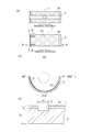
- A The top view which shows the half member which comprises the slide bearing which concerns on one Embodiment.
- B A sectional view taken along the line AA.
- C Similarly, a cross-sectional view along the line BB.
- FIG. 1 is a front view of a plain bearing 1 according to an embodiment of the present invention.
- the vertical direction of the screen in FIG. 1 is the vertical direction of the bearing 1
- the front and back directions of the screen are the axial directions of the bearing 1
- the horizontal direction of the screen is the horizontal direction of the bearing 1.
- the slide bearing 1 is a cylindrical member and is applied to a slide bearing structure of an engine crankshaft 11 as shown in FIG.
- the plain bearing 1 is composed of two halved members 2 and 2.
- Each of the two halved members 2 and 2 has a shape obtained by dividing a cylinder into two in parallel to the axial direction, and is formed so that a cross-sectional shape by a plane orthogonal to the front-rear direction is a semicircular shape.
- the half members 2 and 2 are arranged up and down, and mating surfaces are arranged on the left and right.
- FIG. 2A shows the upper and lower half members 2.
- the rotation direction of the crankshaft 11 is the clockwise direction when viewed from the front as shown by the arrows in FIGS. 1 and 2A and 2B.
- the bearing angle is 0 degree at the right end position in FIG. 2B, and the counterclockwise direction in FIG. 2B is positive. That is, in FIG. 2B, the bearing angle at the left end position is defined as 180 degrees and the bearing angle at the lower end position is defined as 270 degrees.
- the plain bearing 1 is composed of a binder resin and at least one of a solid lubricant and a hard material on the inner peripheral surfaces of the upper and lower halved members 2 and 2. It is covered with a resin overlay layer 2a (the shaded portion in FIGS. 2A to 2C).
- the resin overlay layer 2a is used to prevent damage to the inner peripheral surface of the slide bearing 1 and to reduce friction and wear.
- the binder resin is an adhesive layer for firmly bonding at least one of the solid lubricant and the hard material and the half members 2 and 2.
- a polyamideimide (PAI) resin or a polyimide resin is used.
- PAI polyamideimide
- a phenol resin, a polyacetal resin, a polyether ether ketone resin, and a polyphenylene sulfide resin is used.
- a solid lubricant is a substance that reduces friction and wear by being applied to a friction surface.
- MoS 2 polytetrafluoroethylene (PTFE), graphite, WS 2 , and hexagonal crystals are used. It is composed of at least one of boron nitride (h-BN) and SB 2 O 3 .
- the hard material is a substance that reduces friction and wear by being applied to the friction surface.
- the resin overlay layer 2a may be composed of a binder resin and a solid lubricant, may be composed of a binder resin and a hard material, or is composed of a composite of a binder resin, a solid lubricant, and a hard material. May be.
- a groove is provided in the circumferential direction on the inner periphery of the upper half member 2, and a circular hole is provided in the center.
- mating surfaces are arranged on the left and right of the upper half member 2.
- the inner peripheral surface of the upper half member 2 is coated with a resin overlay layer 2a at portions other than the groove.
- the axial end is circular from the downstream-side mating surface (bearing angle is 180 degrees) toward the direction in which the bearing angle is positive (counterclockwise direction).
- a narrow groove 3 is provided in the circumferential direction.
- the inner peripheral surface of the upper half member 2 is coated with a resin overlay layer 2a except for the narrow grooves 3.
- the narrow groove 3 is provided in the lower half member 2.
- two narrow grooves 3 are provided in parallel in the axial direction.
- the narrow groove 3 is provided in a circumferential direction from the mating surface on the downstream side in the rotation direction of the crankshaft 11 (bearing angle ⁇ is 180 degrees) toward the direction in which the bearing angle ⁇ is positive (counterclockwise direction). It is done. That is, in the lower half member 2, the right mating surface in FIG. 2B is the upstream mating surface in the rotational direction, and the left mating surface in FIG. 2B is the downstream mating surface in the rotational direction.
- the narrow groove 3 is formed to have a depth d shallower than the bearing thickness D, as shown in FIG.
- the narrow groove 3 is formed to have a width of w.
- the sliding area required for the conforming process is reduced, the conforming time at the start of operation is shortened, and the fluid lubrication operation can be shifted to early.
- the narrow groove 3 is provided, the sliding area is reduced, so that the friction can be reduced.
- the pressure gradient at the axial end of the slide bearing 1 can be changed. That is, with the increase in the pressure gradient descending from the bearing end toward the center in the narrow groove 3, the amount of oil sucked back increases and the total amount of spilled oil is suppressed.
- the resin overlay layer 2a by covering with the resin overlay layer 2a, it is possible to prevent the load capacity and the oil film thickness from being reduced by providing the narrow groove 3. That is, by coating with the resin overlay layer 2a, the friction is reduced and the wear resistance is improved as compared with the case where it is not coated, so that the load capacity can be increased and the oil film thickness can be maintained. Therefore, it is possible to prevent the load capacity and the oil film thickness from being reduced by providing the narrow groove 3.
- the half members 2 and 2 which are divided into two cylinders in parallel with the axial direction are arranged vertically, and the inner peripheral surfaces of the upper and lower half members 2 are made of a binder resin, a solid lubricant and a hard material.
- a sliding bearing 1 covered with a resin overlay layer 2a composed of at least one of the lower half member 2 and the axial end of the lower half member 2 from a downstream facing surface in a rotational direction to a predetermined bearing angle.
- the narrow grooves 3 are provided in the circumferential direction.
Landscapes
- Engineering & Computer Science (AREA)
- General Engineering & Computer Science (AREA)
- Mechanical Engineering (AREA)
- Chemical & Material Sciences (AREA)
- Oil, Petroleum & Natural Gas (AREA)
- Sliding-Contact Bearings (AREA)
- Shafts, Cranks, Connecting Bars, And Related Bearings (AREA)
Abstract
軸受の内周面をバインダー樹脂と、固体潤滑剤及び硬質物の少なくとも一つと、から構成される樹脂オーバレイ層で被覆したすべり軸受であって、運転開始時のなじみ時間を短縮し、フリクション低減の効果や耐摩耗性向上の効果を得ることができるすべり軸受を提供する。すべり軸受1は、円筒を軸方向と平行に二分割した半割部材2・2を上下に配置し、前記上下の半割部材2の内周面をバインダー樹脂と、固体潤滑剤及び硬質物の少なくとも一つと、から構成される樹脂オーバレイ層2aで被覆しているすべり軸受であって、前記下側の半割部材2の軸方向端部に回転方向下流側合わせ面から所定の軸受角度まで円周方向に細溝3を設けた。
Description
本発明は、すべり軸受の技術に関し、円筒を軸方向と平行に二分割した半割部材を上下に配置したすべり軸受の技術に関する。
従来、エンジンのクランクシャフトを軸支するための軸受であって、円筒形状を二分割した二つの部材を合わせる半割れ構造のすべり軸受が公知となっている(例えば、特許文献1参照)。また、従来、軸受の内周面をバインダー樹脂と、固体潤滑剤及び硬質物の少なくとも一方と、から構成される樹脂オーバレイ層で被覆した軸受が公知となっている。軸受の内周面をバインダー樹脂と、固体潤滑剤及び硬質物の少なくとも一方と、から構成される樹脂オーバレイ層で被覆したことにより、軸受とクランクシャフトとの接触によるフリクションを低減し、耐摩耗性を向上させるものである。
しかし、従来技術の如く、軸受の内周面をバインダー樹脂と、固体潤滑剤及び硬質物の少なくとも一方と、から構成される樹脂オーバレイ層で被覆した場合、なじみ性が低下するため運転開始時のなじみ時間が長くかかってしまっていた。また、樹脂オーバレイ層で被覆したことによるフリクション低減の効果や耐摩耗性向上の効果は混合、境界潤滑領域においてのみ発揮され、流体潤滑領域においては効果が無かった。
そこで、本発明は係る課題に鑑み、軸受の内周面をバインダー樹脂と、固体潤滑剤及び硬質物の少なくとも一つと、から構成される樹脂オーバレイ層で被覆したすべり軸受であって、運転開始時のなじみ時間を短縮し、フリクション低減の効果や耐摩耗性向上の効果を得ることができるすべり軸受を提供する。
本発明の解決しようとする課題は以上の如くであり、次にこの課題を解決するための手段を説明する。
即ち、請求項1においては、円筒を軸方向と平行に二分割した半割部材を上下に配置し、前記上下の半割部材の内周面をバインダー樹脂と、固体潤滑剤及び硬質物の少なくとも一つと、から構成される樹脂オーバレイ層で被覆したすべり軸受であって、前記下側の半割部材の軸方向端部に回転方向下流側合わせ面から所定の軸受角度まで円周方向に細溝を設けたものである。
本発明の効果として、以下に示すような効果を奏する。
すなわち、細溝を設けたことによりなじみ工程が必要な摺動面積が減少し、運転開始時のなじみ時間が短縮され早期に流体潤滑運転へ移行することができる。また、流体潤滑運転時においても摺動面積の減少によりフリクション低減の効果を得ることができ、耐摩耗性向上の効果を得ることができる。
次に、発明の実施の形態を説明する。なお、図1は本発明の一実施形態に係るすべり軸受1の正面図であり、図1における画面の上下方向を軸受1の上下方向、画面の手前方向及び奥方向を軸受1の軸方向(前後方向)、画面の左右方向を軸受1の左右方向とする。
まず、すべり軸受1を構成する半割部材2について図1及び図2を用いて説明する。
すべり軸受1は円筒状の部材であり、図1に示すように、エンジンのクランクシャフト11のすべり軸受構造に適用される。すべり軸受1は、二つの半割部材2・2で構成されている。二つの半割部材2・2は、それぞれが円筒を軸方向と平行に二分割した形状であり、前後方向と直交する平面による断面形状が半円状となるように形成されている。本実施形態においては、半割部材2・2は上下に配置されており、左右に合わせ面が配置されている。クランクシャフト11をすべり軸受1で軸支する場合、所定の隙間が形成され、この隙間に対し図示せぬ油路から潤滑油が供給される。
すべり軸受1は円筒状の部材であり、図1に示すように、エンジンのクランクシャフト11のすべり軸受構造に適用される。すべり軸受1は、二つの半割部材2・2で構成されている。二つの半割部材2・2は、それぞれが円筒を軸方向と平行に二分割した形状であり、前後方向と直交する平面による断面形状が半円状となるように形成されている。本実施形態においては、半割部材2・2は上下に配置されており、左右に合わせ面が配置されている。クランクシャフト11をすべり軸受1で軸支する場合、所定の隙間が形成され、この隙間に対し図示せぬ油路から潤滑油が供給される。
図2(a)においては、上側および下側の半割部材2を示している。なお、本実施形態においては、クランクシャフト11の回転方向を図1及び図2(a)・(b)の矢印に示すように正面視時計回り方向とする。また、軸受角度は、図2(b)における右端の位置を0度とし、図2(b)において、反時計回り方向を正とする。すなわち、図2(b)において、左端の位置の軸受角度が180度となり、下端の位置の軸受角度が270度となるように定義する。
図2(a)から(c)に示す如く、すべり軸受1は、上下の半割部材2・2の内周面をバインダー樹脂と、固体潤滑剤及び硬質物の少なくとも一つと、から構成される樹脂オーバレイ層2aで被覆している(図2(a)から(c)において網掛けされた部分)。樹脂オーバレイ層2aはすべり軸受1の内周面における損傷を防止したり、摩擦・摩耗を低減したりするために用いられる。
バインダー樹脂は、固体潤滑剤及び硬質物の少なくとも一つと半割部材2・2とを強固に接着させるための接着層であり、例えば、本実施形態においては、ポリアミドイミド(PAI)樹脂、ポリイミド樹脂、フェノール樹脂、ポリアセタール樹脂、ポリエーテルエーテルケトン樹脂、ポリフェニレンサルファイド樹脂の少なくともいずれか一つ以上で構成される。
固体潤滑剤は、摩擦面に付与することによって摩擦や摩耗を低下させる物質であり、例えば、本実施形態においては、MoS2、ポリテトラフルオロエチレン(PTFE)、グラファイト、WS2、六方晶系の窒化ホウ素(h-BN)、SB2O3、の少なくともいずれか一つ以上で構成される。
硬質物は、摩擦面に付与することによって摩擦や摩耗を低下させる物質であり、例えば、本実施形態においては、SiC、AlO3、TiN、AlN、CrO2、Si3N4、ZrO2、Fe3Pの少なくともいずれか一つ以上で構成される。
樹脂オーバレイ層2aは、バインダー樹脂と固体潤滑剤とから構成されても良いし、バインダー樹脂と硬質物とから構成されても良いし、バインダー樹脂と固体潤滑剤及び硬質物の合成物とから構成されても良い。
上側の半割部材2の内周には円周方向に溝が設けられており、中心に円形の孔が設けられている。また、上側の半割部材2の左右に合わせ面が配置されている。図2(a)に示す如く、上側の半割部材2の内周面はこの溝以外の部分が樹脂オーバレイ層2aでコーティングされている。
下側の半割部材2の内周面においては、軸方向端部に回転方向下流側合わせ面(軸受角度が180度)から軸受角度が正となる方向(反時計回り方向)に向けて円周方向に細溝3が設けられている。上側の半割部材2の内周面はこの細溝3を除いて、樹脂オーバレイ層2aでコーティングされている。
細溝3は下側の半割部材2に設けられる。本実施形態においては、細溝3は軸方向に並列して二本設けられている。詳細には、細溝3は、クランクシャフト11の回転方向下流側合わせ面(軸受角度ωが180度)から軸受角度ωが正となる方向(反時計回り方向)に向けて円周方向に設けられる。すなわち、下側の半割部材2においては、図2(b)の右側の合わせ面が回転方向上流側合わせ面、図2(b)の左側の合わせ面が回転方向下流側合わせ面となる。
細溝3は、図2(c)に示すように、軸受厚さDよりも浅い深さdとなるように形成されている。また、細溝3の幅はwとなるように形成されている。
細溝3は、図2(c)に示すように、軸受厚さDよりも浅い深さdとなるように形成されている。また、細溝3の幅はwとなるように形成されている。
細溝3を設けたことにより、なじみ工程に必要な摺動面積が減少し、運転開始時のなじみ時間が短縮され早期に流体潤滑運転へ移行することができる。また、細溝3を設けたことにより、摺動面積が減少するため、フリクションを低減させることが可能となった。
また、細溝3を設けたことにより、すべり軸受1の軸方向端部における圧力勾配を変化させることができる。すなわち、細溝3において軸受端部から中央部へ向かって下降する圧力勾配の増加に伴って、油の吸い戻し量が増加し、総和の流出油量が抑制される。
また、樹脂オーバレイ層2aで被覆したことにより、細溝3を設けることで発生する負荷容量の減少や、油膜厚さの低下を防止することができる。すなわち、樹脂オーバレイ層2aで被覆したことにより、コーティングしていない場合と比較してフリクションが低減し、耐摩耗性が向上するため、負荷容量を増加させて、油膜厚さを維持することができるので細溝3を設けることで発生する負荷容量の減少や、油膜厚さの低下を防止することができる。
以上のように、円筒を軸方向と平行に二分割した半割部材2・2を上下に配置し、前記上下の半割部材2の内周面をバインダー樹脂と、固体潤滑剤及び硬質物の少なくとも一つと、から構成される樹脂オーバレイ層2aで被覆しているすべり軸受1であって、前記下側の半割部材2の軸方向端部に回転方向下流側合わせ面から所定の軸受角度まで円周方向に細溝3を設けたものである。
このように構成することにより、細溝3を設けたことによりなじみ工程が必要な摺動面積が減少し、運転開始時のなじみ時間が短縮され早期に流体潤滑運転へ移行することができる。また、流体潤滑運転時においても摺動面積の減少によりフリクション低減の効果を得ることができ、耐摩耗性向上の効果を得ることができる。
このように構成することにより、細溝3を設けたことによりなじみ工程が必要な摺動面積が減少し、運転開始時のなじみ時間が短縮され早期に流体潤滑運転へ移行することができる。また、流体潤滑運転時においても摺動面積の減少によりフリクション低減の効果を得ることができ、耐摩耗性向上の効果を得ることができる。
1 すべり軸受
2 半割部材
2a 樹脂オーバレイ層
3 細溝
11 クランクシャフト
2 半割部材
2a 樹脂オーバレイ層
3 細溝
11 クランクシャフト
Claims (1)
- 円筒を軸方向と平行に二分割した半割部材を上下に配置し、
前記上下の半割部材の内周面をバインダー樹脂と、固体潤滑剤及び硬質物の少なくとも一つと、から構成される樹脂オーバレイ層で被覆したすべり軸受であって、
前記下側の半割部材の軸方向端部に回転方向下流側合わせ面から所定の軸受角度まで円周方向に細溝を設けた、ことを特徴とするすべり軸受。
Priority Applications (3)
| Application Number | Priority Date | Filing Date | Title |
|---|---|---|---|
| US15/111,313 US9933007B2 (en) | 2014-01-15 | 2015-01-13 | Sliding bearing |
| EP15737742.5A EP3096031B1 (en) | 2014-01-15 | 2015-01-13 | Sliding bearing |
| CN201580004238.4A CN105899825B (zh) | 2014-01-15 | 2015-01-13 | 滑动轴承 |
Applications Claiming Priority (2)
| Application Number | Priority Date | Filing Date | Title |
|---|---|---|---|
| JP2014-005349 | 2014-01-15 | ||
| JP2014005349A JP6266986B2 (ja) | 2014-01-15 | 2014-01-15 | すべり軸受 |
Publications (1)
| Publication Number | Publication Date |
|---|---|
| WO2015108031A1 true WO2015108031A1 (ja) | 2015-07-23 |
Family
ID=53542920
Family Applications (1)
| Application Number | Title | Priority Date | Filing Date |
|---|---|---|---|
| PCT/JP2015/050659 Ceased WO2015108031A1 (ja) | 2014-01-15 | 2015-01-13 | すべり軸受 |
Country Status (5)
| Country | Link |
|---|---|
| US (1) | US9933007B2 (ja) |
| EP (1) | EP3096031B1 (ja) |
| JP (1) | JP6266986B2 (ja) |
| CN (1) | CN105899825B (ja) |
| WO (1) | WO2015108031A1 (ja) |
Cited By (3)
| Publication number | Priority date | Publication date | Assignee | Title |
|---|---|---|---|---|
| CN109983241A (zh) * | 2016-10-31 | 2019-07-05 | 大丰工业株式会社 | 半轴承 |
| US20190271355A1 (en) * | 2016-10-31 | 2019-09-05 | Taiho Kogyo Co., Ltd. | Half bearing |
| US20200063797A1 (en) * | 2016-12-09 | 2020-02-27 | Taiho Kogyo Co., Ltd. | Half bearing |
Families Citing this family (1)
| Publication number | Priority date | Publication date | Assignee | Title |
|---|---|---|---|---|
| JP2018096408A (ja) * | 2016-12-09 | 2018-06-21 | 大豊工業株式会社 | 半割軸受 |
Citations (4)
| Publication number | Priority date | Publication date | Assignee | Title |
|---|---|---|---|---|
| JPH0463810U (ja) * | 1990-10-09 | 1992-05-29 | ||
| JP2003532036A (ja) | 2000-05-03 | 2003-10-28 | デーナ、コーポレイション | 軸 受 |
| WO2012069191A1 (en) * | 2010-11-24 | 2012-05-31 | Mahle International Gmbh | Bearing with integrated seals |
| DE102012210530A1 (de) * | 2012-06-21 | 2013-12-24 | Federal-Mogul Wiesbaden Gmbh | Pleuelgleitlager |
Family Cites Families (26)
| Publication number | Priority date | Publication date | Assignee | Title |
|---|---|---|---|---|
| CH304821A (de) * | 1952-03-21 | 1955-01-31 | Conradty Fa C | Selbstdichtendes Gleitlager. |
| JPS58183174U (ja) * | 1982-05-31 | 1983-12-06 | 第一樹脂工業株式会社 | 食卓カバ− |
| JPS6017180U (ja) * | 1983-07-13 | 1985-02-05 | 篠崎 田鶴子 | 折畳み可能な簡易カバ− |
| JPH0833259A (ja) | 1994-07-22 | 1996-02-02 | Meidensha Corp | すべり軸受装置 |
| JPH08121459A (ja) | 1994-10-27 | 1996-05-14 | Yanmar Diesel Engine Co Ltd | ディーゼル機関の軸受構造 |
| JP3245064B2 (ja) | 1996-07-18 | 2002-01-07 | 大豊工業株式会社 | すべり軸受 |
| CN2360670Y (zh) * | 1997-10-13 | 2000-01-26 | 合肥工业大学科教开发部 | 新型复合自润滑板材 |
| JP2002155945A (ja) * | 2000-11-20 | 2002-05-31 | Daido Metal Co Ltd | 軸支承部材 |
| JP3623737B2 (ja) * | 2000-12-25 | 2005-02-23 | 大同メタル工業株式会社 | 半割軸受 |
| JP2002276646A (ja) * | 2001-03-16 | 2002-09-25 | Hitachi Ltd | ラジアル軸受及びこれを用いた変速機 |
| JP3949117B2 (ja) * | 2004-03-12 | 2007-07-25 | 大同メタル工業株式会社 | すべり軸受 |
| JP4515824B2 (ja) * | 2004-05-27 | 2010-08-04 | Ntn株式会社 | 高精度すべり軸受 |
| JP2006138353A (ja) | 2004-11-10 | 2006-06-01 | Toshiba Corp | すべり軸受及びすべり軸受を備えた回転電機 |
| JP3136166U (ja) * | 2007-07-13 | 2007-10-18 | 五郎 小池 | 折り畳み式卓上携帯保冷装置。 |
| DE102008039740A1 (de) * | 2008-08-26 | 2010-03-04 | Mahle International Gmbh | Gleitlager |
| DE102008055194A1 (de) * | 2008-12-30 | 2010-07-08 | Federal-Mogul Wiesbaden Gmbh | Gleitelement |
| JP4864108B2 (ja) * | 2009-02-27 | 2012-02-01 | 大同メタル工業株式会社 | 内燃機関のコンロッド軸受 |
| CN102345678B (zh) * | 2011-06-17 | 2013-04-10 | 浙江长盛滑动轴承股份有限公司 | 改性聚酰亚胺耐磨层的三层复合自润滑滑动轴承及其制作方法 |
| JP5597173B2 (ja) | 2011-09-08 | 2014-10-01 | 大同メタル工業株式会社 | 内燃機関のコンロッド軸受 |
| JP5895638B2 (ja) | 2012-03-21 | 2016-03-30 | 大豊工業株式会社 | すべり軸受 |
| EP2940327B1 (en) * | 2012-12-27 | 2020-06-24 | Taiho Kogyo Co., Ltd | Sliding member |
| JP6390038B2 (ja) | 2013-02-20 | 2018-09-19 | 大豊工業株式会社 | すべり軸受、及び、すべり軸受の製造方法 |
| JP5837896B2 (ja) * | 2013-03-21 | 2015-12-24 | 大豊工業株式会社 | すべり軸受 |
| JP6096689B2 (ja) * | 2013-04-26 | 2017-03-15 | 大豊工業株式会社 | すべり軸受 |
| JP6134636B2 (ja) * | 2013-11-12 | 2017-05-24 | 大豊工業株式会社 | すべり軸受 |
| JP6216226B2 (ja) * | 2013-11-12 | 2017-10-18 | 大豊工業株式会社 | すべり軸受 |
-
2014
- 2014-01-15 JP JP2014005349A patent/JP6266986B2/ja not_active Expired - Fee Related
-
2015
- 2015-01-13 US US15/111,313 patent/US9933007B2/en active Active
- 2015-01-13 WO PCT/JP2015/050659 patent/WO2015108031A1/ja not_active Ceased
- 2015-01-13 CN CN201580004238.4A patent/CN105899825B/zh not_active Expired - Fee Related
- 2015-01-13 EP EP15737742.5A patent/EP3096031B1/en active Active
Patent Citations (4)
| Publication number | Priority date | Publication date | Assignee | Title |
|---|---|---|---|---|
| JPH0463810U (ja) * | 1990-10-09 | 1992-05-29 | ||
| JP2003532036A (ja) | 2000-05-03 | 2003-10-28 | デーナ、コーポレイション | 軸 受 |
| WO2012069191A1 (en) * | 2010-11-24 | 2012-05-31 | Mahle International Gmbh | Bearing with integrated seals |
| DE102012210530A1 (de) * | 2012-06-21 | 2013-12-24 | Federal-Mogul Wiesbaden Gmbh | Pleuelgleitlager |
Non-Patent Citations (1)
| Title |
|---|
| See also references of EP3096031A4 * |
Cited By (5)
| Publication number | Priority date | Publication date | Assignee | Title |
|---|---|---|---|---|
| CN109983241A (zh) * | 2016-10-31 | 2019-07-05 | 大丰工业株式会社 | 半轴承 |
| US20190271354A1 (en) * | 2016-10-31 | 2019-09-05 | Taiho Kogyo Co., Ltd. | Half bearing |
| US20190271355A1 (en) * | 2016-10-31 | 2019-09-05 | Taiho Kogyo Co., Ltd. | Half bearing |
| CN109983241B (zh) * | 2016-10-31 | 2021-10-22 | 大丰工业株式会社 | 半轴承 |
| US20200063797A1 (en) * | 2016-12-09 | 2020-02-27 | Taiho Kogyo Co., Ltd. | Half bearing |
Also Published As
| Publication number | Publication date |
|---|---|
| US20160333922A1 (en) | 2016-11-17 |
| EP3096031A4 (en) | 2017-11-01 |
| JP6266986B2 (ja) | 2018-01-24 |
| CN105899825B (zh) | 2018-04-17 |
| CN105899825A (zh) | 2016-08-24 |
| JP2015132367A (ja) | 2015-07-23 |
| US9933007B2 (en) | 2018-04-03 |
| EP3096031A1 (en) | 2016-11-23 |
| EP3096031B1 (en) | 2021-05-05 |
Similar Documents
| Publication | Publication Date | Title |
|---|---|---|
| JP5837896B2 (ja) | すべり軸受 | |
| JP6185853B2 (ja) | すべり軸受 | |
| JP6228558B2 (ja) | スラストすべり軸受 | |
| JP6266986B2 (ja) | すべり軸受 | |
| JP2016166662A5 (ja) | ||
| JP6134636B2 (ja) | すべり軸受 | |
| CN105008733B (zh) | 滑动轴承 | |
| CN107429744A (zh) | 滑动轴承的制造方法及滑动轴承 | |
| JP6317965B2 (ja) | 軸受 | |
| JP6216226B2 (ja) | すべり軸受 | |
| CN107250576A (zh) | 滑动轴承的制造方法以及滑动轴承 | |
| WO2016136995A1 (ja) | すべり軸受 | |
| JP2018087583A (ja) | スラストワッシャ | |
| JP6283238B2 (ja) | 軸受 | |
| JP2017110762A (ja) | すべり軸受 | |
| WO2016136994A1 (ja) | すべり軸受の製造方法及びすべり軸受 | |
| JP2015197214A (ja) | すべり軸受 | |
| WO2018097293A1 (ja) | スラストワッシャ | |
| CN110139991A (zh) | 半轴承 | |
| JP2018087582A (ja) | スラストワッシャ | |
| JP2017110761A (ja) | すべり軸受 |
Legal Events
| Date | Code | Title | Description |
|---|---|---|---|
| 121 | Ep: the epo has been informed by wipo that ep was designated in this application |
Ref document number: 15737742 Country of ref document: EP Kind code of ref document: A1 |
|
| DPE1 | Request for preliminary examination filed after expiration of 19th month from priority date (pct application filed from 20040101) | ||
| WWE | Wipo information: entry into national phase |
Ref document number: 15111313 Country of ref document: US |
|
| NENP | Non-entry into the national phase |
Ref country code: DE |
|
| REEP | Request for entry into the european phase |
Ref document number: 2015737742 Country of ref document: EP |
|
| WWE | Wipo information: entry into national phase |
Ref document number: 2015737742 Country of ref document: EP |