WO2015111132A1 - Appareil de radiothérapie - Google Patents
Appareil de radiothérapie Download PDFInfo
- Publication number
- WO2015111132A1 WO2015111132A1 PCT/JP2014/051090 JP2014051090W WO2015111132A1 WO 2015111132 A1 WO2015111132 A1 WO 2015111132A1 JP 2014051090 W JP2014051090 W JP 2014051090W WO 2015111132 A1 WO2015111132 A1 WO 2015111132A1
- Authority
- WO
- WIPO (PCT)
- Prior art keywords
- gantry
- support
- rail
- sliding member
- central axis
- Prior art date
- Legal status (The legal status is an assumption and is not a legal conclusion. Google has not performed a legal analysis and makes no representation as to the accuracy of the status listed.)
- Ceased
Links
Images

Classifications
-
- A—HUMAN NECESSITIES
- A61—MEDICAL OR VETERINARY SCIENCE; HYGIENE
- A61N—ELECTROTHERAPY; MAGNETOTHERAPY; RADIATION THERAPY; ULTRASOUND THERAPY
- A61N5/00—Radiation therapy
- A61N5/10—X-ray therapy; Gamma-ray therapy; Particle-irradiation therapy
- A61N5/1077—Beam delivery systems
- A61N5/1081—Rotating beam systems with a specific mechanical construction, e.g. gantries
-
- A—HUMAN NECESSITIES
- A61—MEDICAL OR VETERINARY SCIENCE; HYGIENE
- A61N—ELECTROTHERAPY; MAGNETOTHERAPY; RADIATION THERAPY; ULTRASOUND THERAPY
- A61N5/00—Radiation therapy
- A61N5/01—Devices for producing movement of radiation source during therapy
Definitions
- the present invention relates to a radiation treatment apparatus that irradiates radiation to a patient from multiple directions.
- One of the treatment methods for tumors is radiation therapy in which the affected area is irradiated with radiation.
- radiation therapy it is desirable to efficiently irradiate the affected area with radiation while suppressing the radiation dose (dose) to the patient as much as possible.
- stereotactic radiosurgery that can irradiate radiation to the affected area of a patient from multiple directions is used.
- Patent Document 1 discloses an annular support frame 1 provided so as to surround a patient's body axis, and a support frame 1.
- a configuration is disclosed that includes an annular rail 2 provided on the side surface of the ring, and an annular gantry 4 rotatable around a horizontal axis along the rail 2 and provided with the irradiation unit 3. There is.
- the radiation irradiating unit 3 provided on the gantry 4 is pivoted around the patient's body axis, and the patient is viewed from many directions. Irradiate the radiation.
- the annular support frame 1 for supporting the rail 2 must have high strength in order to ensure the accuracy of the rail 2. As a result, the weight of the entire radiotherapy apparatus is increased.
- the support frame 1 the lowermost end portion 1 a located vertically below the central axis of the support frame 1 is supported on the turning mechanism 6 in order to turn the support frame 1 around the vertical axis.
- the support frame 1 is easily deformed into an elliptical shape so as to be crushed in the vertical direction by the weight of the gantry 4 and the weight of the support frame 1 itself. If the rails 2 are also deformed in accordance with this deformation, the positional accuracy of the gantry 4 may be adversely affected, which may require a correction or the turning of the gantry 4 may become difficult. If the strength of the support frame 1 is increased to prevent this, the weight will further increase.
- An object of the present invention is to provide a radiotherapy apparatus capable of suppressing the enlargement of the apparatus and reducing the apparatus weight while improving the positional accuracy of the gantry.
- a radiation treatment apparatus includes an annular gantry, an irradiation unit provided on the gantry for irradiating radiation, a support for supporting the gantry, the gantry, and the support. And a rotary drive mechanism provided between the body and for rotating the gantry around a central axis of the gantry, wherein the rotary drive mechanism includes an annular rail provided on the gantry, and the support at the support. And a first sliding member provided in a region corresponding to the lower half of the gantry, slidably guiding the rail, and receiving at least a vertical load of the gantry.
- the rotary drive mechanism in the radiotherapy apparatus of the first aspect is laterally offset with respect to the vertically lower position of the central axis of the gantry in the support.
- a second sliding member may be provided, which is provided at the same position, slidably guides the rail, and restricts horizontal displacement of the gantry.
- the first sliding member and the second sliding member in the radiotherapy apparatus according to the first or second aspect are perpendicular to the central axis of the gantry. It may be arranged in line symmetry with respect to the axis.
- the radiation therapy apparatus further comprises a pivoting mechanism for pivotably supporting the support in the radiation therapy apparatus according to any one of the first to third aspects. You may
- the pivoting mechanism in the radiotherapy apparatus of the fourth aspect has a rotation axis having a center in the vertical axis direction, and the first sliding member or the first sliding member The second sliding member may be disposed vertically above the rotation shaft.
- a radiotherapy apparatus comprising: a base on which the pivoting mechanism in the radiotherapy apparatus according to any one of the first to fifth aspects is installed on a floor; A pivoting rail provided on one of the supports and circumferentially continuous about the vertical axis; and a pivoting guide provided on the other of the base and the support and slidable along the pivoting rail.
- the base may further include an accommodating portion in which at least a part of the gantry is accommodated on an inner circumferential side of the swing rail.
- the radiation treatment apparatus it is possible to suppress the enlargement of the apparatus and reduce the weight of the apparatus while improving the positional accuracy of the gantry.
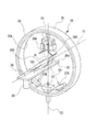
- FIG. 1 is a perspective view showing a schematic configuration of a radiation treatment apparatus 20.
- the radiation treatment apparatus 20 includes a gantry 30 and a radiation irradiation unit (irradiation unit) 24.
- the gantry 30 has a cylindrical shape with a circular cross section.
- the gantry 30 is rotatable in a vertical plane around a horizontal central axis C1 extending in the horizontal direction by a vertical rotation mechanism (rotational drive mechanism) 40A (see FIGS. 2 and 3) described later.
- the gantry 30 can be pivoted in a horizontal plane around a vertical central axis (vertical axis) C2 extending in the vertical direction by a horizontal pivot drive mechanism (turning mechanism) 50A (see FIGS. 2 and 3) described later. .
- the radiation irradiator 24 is supported by the inner circumferential surface 30 a of the gantry 30.
- the radiation irradiator 24 is controlled by a controller (not shown) to emit therapeutic radiation Sr.
- the therapeutic radiation Sr emitted from the radiation irradiator 24 is adjusted to pass through the isocenter C0 set at the intersection of the horizontal central axis C1 and the vertical central axis C2.
- the radiation irradiator 24 is supported by the gantry 30, and the treatment radiation Sr does not matter whether the rotational movement of the gantry 30 around the vertical central axis C2 or the horizontal central axis C1 of the gantry 30 is performed. It is always emitted through the isocenter C0.
- the radiation treatment apparatus 20 further includes a sensor array 22.
- the sensor array 22 receives the therapeutic radiation Sr emitted by the radiation irradiator 24 and transmitted through the subject around the isocenter C0, and generates a transmission image of the subject.
- a flat panel detector (FPD), an X-ray II (image intensifier), or the like can be used as the sensor array 22.
- the radiation treatment apparatus 20 further includes diagnostic X-ray sources 26A and 26B and sensor arrays 27A and 27B.
- the diagnostic X-ray sources 26A and 26B are disposed on the inner peripheral side of the gantry 30.
- the diagnostic X-ray sources 26A and 26B are disposed on both sides in the circumferential direction of the gantry 30, with the center of the radiation treatment apparatus 20 (in other words, the vertical central axis C2) interposed.
- the diagnostic X-ray sources 26A and 26B are controlled by a controller (not shown) to emit diagnostic X-rays 101 toward the isocenter C0.
- the diagnostic X-ray 101 is a cone-like cone beam that extends conically from one point of the diagnostic X-ray source 26A, 26B.
- the diagnostic X-ray 101 is not limited to a conical shape, and may be, for example, a pyramid shape or the like by cutting out a necessary range with a collimator (not shown).
- the sensor arrays 27A and 27B are supported by the inner circumferential surface 30a of the gantry 30.
- the sensor arrays 27A and 27B are disposed to face the diagnostic X-ray sources 26A and 26B across the isocenter C0.
- the sensor arrays 27A and 27B receive the diagnostic X-rays 101 emitted from the diagnostic X-ray sources 26A and 26B and transmitted through the object around the isocenter C0, and generate a transmission image of the object.
- FPD Full Panel Detector
- X-ray II Image Intensifier
- the radiation treatment apparatus 20 further includes a couch 28 and a couch driving device 29.
- the couch 28 is provided with an upper surface 28 a on which the patient 200 to be treated by the radiation treatment apparatus 20 sleeps.
- the couch drive device 29 supports the couch 28 on a base (not shown), and is controlled by a controller (not shown) to move the couch 28.
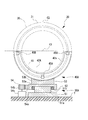
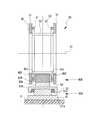
- FIG. 2 is a front view showing a drive mechanism of the gantry 30 in the radiation treatment apparatus 20 in the first embodiment.
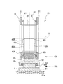
- FIG. 3 is a side sectional view showing the drive mechanism of the gantry 30.
- the radiotherapy apparatus 20 includes a vertical rotation mechanism 40A rotatably supporting the gantry 30 around a horizontal central axis C1 extending in the horizontal direction, the gantry 30, and the vertical rotation mechanism 40A.
- a horizontal pivoting drive mechanism 50A that pivotably supports the vertical pivot axis C2 extending in the vertical direction.
- the gantry 30 has a pair of annular ring frames 31, 31 arranged in parallel with each other at intervals in the direction along the horizontal central axis C1.
- the ring frames 31, 31 are integrally connected by a plurality of connecting beam members 32 provided at intervals in the circumferential direction.
- a reinforcement (not shown) having a truss structure or the like is provided for reinforcement.
- An annular gantry rail (rail) 41 is integrally provided on each ring frame 31 on the side where the ring frames 31 face each other.
- the gantry 30 is covered by a cover 35, and on its inner circumferential surface 30a, as described above, the radiotherapy apparatus 20, the sensor array 22, the diagnostic X-ray source 26A, 26B, the sensor array 27A, 27B is attached.
- the vertical rotation mechanism 40A includes the gantry rail 41, a sliding member (first sliding member) 45A slidably guiding the gantry rail 41, and a sliding member A second sliding member) 45B.
- the sliding members 45A, 45B are attached to a support 42A disposed between a pair of ring frames 31, 31 constituting the gantry 30.
- the sliding members 45A and 45B are respectively provided on the side surfaces 42s and 42s facing the pair of ring frames 31 and 31 in the support 42A.
- the support 42A has a semicircular arc shape provided in a range below the horizontal central axis C1 of the gantry 30.
- the sliding members 45 ⁇ / b> A are disposed in a range below the horizontal central axis C ⁇ b> 1 of the gantry 30 on the side surfaces 42 s of the support 42 ⁇ / b> A. More specifically, the sliding member 45A is disposed at the lowermost portion in the circumferential direction of the support 42A. That is, the sliding member 45A is disposed vertically below the horizontal central axis C1.
- the sliding member 45 ⁇ / b> A supports the circumferentially lower portion of the gantry rail 41. The lowermost portion of the gantry rail 41 supported by the sliding member 45A extends in a substantially horizontal direction.
- the sliding member 45A supports the gantry rail 41 slidably in the circumferential direction while restricting the vertical displacement of the gantry rail 41. That is, the sliding member 45A receives a load in the vertical direction of the gantry 30 via the gantry rail 41.
- the sliding members 45B are attached at positions laterally offset from the vertically downward position of the horizontal central axis C1 of the gantry 30 on the side surfaces 42s of the support 42A.
- the sliding members 45B in this embodiment are disposed at positions slightly lower than the horizontal central axis C1 at both ends of the support 42A.
- the portion of the gantry rail 41 supported by the sliding member 45B extends substantially in the vertical direction.
- the sliding member 45B supports the gantry rail 41 slidably in the circumferential direction while restricting the displacement of the gantry rail 41 in the horizontal direction. That is, the sliding member 45 B regulates the displacement of the gantry 30 in the horizontal direction via the gantry rail 41.
- the sliding member 45A and the sliding member 45B are disposed in line symmetry with respect to a vertical central axis C2 passing through the horizontal central axis C1 of the gantry 30.
- the gantry 30 is supported by the support 42A rotatably around a horizontal central axis C1 via the above-described vertical rotation mechanism 40A.
- the gantry 30 can be rotationally driven about a horizontal central axis C1 with respect to the support 42A by a drive source (not shown) such as an electric motor.
- the horizontal turning drive mechanism 50A includes a lower base member 51, an upper base member 53, and a drive unit 54.
- the lower base member 51 is installed on the floor surface F.
- the lower base member 51 includes a base plate 51a installed on the floor F, and a columnar support shaft 51b erected on the base plate 51a.
- An annular bearing 52 is provided at the upper end of the support shaft 51b.
- the upper base member 53 is provided on the lower base member 51.
- the upper base member 53 is rotatable relative to the lower base member 51 about the vertical central axis C2 via the bearing 52.
- the upper base member 53 includes a base plate 53a rotatably supported by the bearing 52, and a rotary shaft (rotational shaft) 53b erected on the base plate 53a.
- the rotation shaft 53b is integrally provided at the lowermost end of the support 42A.
- the driving unit 54 rotationally drives the upper base member 53 around the vertical central axis C2.
- the drive unit 54 includes a gear 54a provided on the upper base member 53 side, and a motor 54c having a drive gear 54b engaged with the gear 54a.
- the horizontal swing drive mechanism 50A when the motor 54c rotates the gear 54a via the drive gear 54b, the upper base member 53 and the support 42A and the gantry 30 are rotationally driven around the vertical central axis C2. Further, according to the horizontal turning drive mechanism 50A, the load in the vertical direction of the gantry 30 supported by the sliding member 45A and the load of the support 42A are applied to the floor F via the support shaft 51b and the rotation shaft 53b. It is transmitted.
- the radiation treatment apparatus 20 having the above configuration performs treatment as follows. First, the user fixes the patient 200 to the couch 28 of the radiation treatment apparatus 20.
- the gantry 30 is pivoted around the horizontal central axis C1 and the vertical central axis C2 by operating the vertical pivoting mechanism 40A and the horizontal pivoting drive mechanism 50A by a controller (not shown).
- the radiation irradiator 24 is moved such that the therapeutic radiation Sr irradiates the affected part position of the patient 200 at a preset irradiation angle. Then, the radiation irradiation unit 24 irradiates a treatment radiation Sr of a preset dose to the affected area of the patient 200.
- the gantry rail 41 is provided on the annular gantry 30 side, and the sliding member 45A for guiding the gantry rail 41 is provided on the support 42A.
- the sliding members 45A, 45B and the support 42A can be provided in the region corresponding to the lower half which is a range below the horizontal central axis C1 of the gantry 30. Therefore, the support 42A does not have to be annular. As a result, deformation of the support 42A in the vertical direction can be suppressed by the weight of the support 42A, and the size and weight of the support 42A can be reduced.
- the sliding member 45A supports the load of the gantry 30 in the vertical direction, and the sliding member 45B restrains the horizontal displacement of the gantry 30, the gantry 30 can be stably rotated.
- the sliding member 45A and the sliding member 45B are arranged in line symmetry with respect to the vertical central axis C2 of the gantry 30, so that the gantry 30 can be stably and rotatably supported.
- the radiation treatment apparatus 20 includes the horizontal swing drive mechanism 50A that supports the support 42A so as to be pivotable about the vertical central axis C2, whereby the gantry 30 can be pivoted about the vertical axis. .
- the degree of freedom of the irradiation direction of the therapeutic radiation Sr on the patient 200 in the irradiation unit 24 can be increased.
- the sliding member 45A which receives the vertical load of the gantry 30 is supported by the sliding member 45A by being disposed vertically above the support shaft portion 51b and the rotation shaft portion 53b. The load in the vertical direction of the gantry 30 is efficiently transmitted to the floor surface F via the support shaft portion 51 b and the rotation shaft portion 53 b.
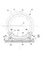
- FIG. 4 is a front view showing a drive mechanism of the gantry 30 in the radiation treatment apparatus 20 in the second embodiment.
- FIG. 5 is a side sectional view showing the drive mechanism of the gantry 30.
- the vertical turning mechanism 40B in this embodiment includes a gantry rail 41 and a sliding member (first sliding member, second sliding) for slidably guiding the gantry rail 41. Members) 45C and 45C.
- the sliding members 45C, 45C are provided on the side surfaces 42s, 42s of the support 42B.
- the support 42 ⁇ / b> B has an arc shape provided in a range below the horizontal central axis C ⁇ b> 1 of the gantry 30.
- the sliding members 45C, 45C are disposed below the horizontal central axis C1 of the gantry 30 and offset laterally from the vertical lower side of the horizontal central axis C1 of the gantry 30.
- the sliding members 45C, 45C are arranged in line symmetry with respect to the vertical central axis C2 of the gantry 30. Further, the sliding members 45C, 45C are disposed in a range vertically above the rotation shaft portion 53b of the horizontal turning drive mechanism 50A. Furthermore, the sliding members 45C, 45C are provided vertically above the bearing 52 of the horizontal turning drive mechanism 50A.
- the gantry rail 41 extends obliquely in the portion of the sliding members 45C, 45C. Therefore, the sliding members 45C, 45C have a function of receiving the load of the gantry 30 in the vertical direction and a function of restraining the displacement of the gantry 30 in the horizontal direction. That is, in this case, the sliding members 45C, 45C have both the functions of the first sliding member and the second sliding member of the present invention.
- the gantry rail 41 is provided on the annular gantry 30 side, and the sliding members 45C and 45C for guiding the gantry rail 41 are used as the support 42B.
- the support 42B With the configuration provided, it is not necessary to make the support 42B annular as in the prior art. As a result, the size and weight of the support 42B can be reduced.
- the sliding members 45C, 45C support the load of the gantry 30 in the vertical direction and restrain the displacement of the gantry 30 in the horizontal direction, whereby the gantry 30 can be stably rotated.
- the sliding members 45C, 45C are disposed vertically above the bearing 52 of the horizontal turning drive mechanism 50A within the range of the vertical top of the rotary shaft portion 53b of the horizontal turning drive mechanism 50A.
- the load in the vertical direction of the gantry 30 supported by 45C and 45C can be efficiently transmitted to the floor surface F via the rotation shaft portion 53b.
- the circumferential length of the support 42B is longer than that of the support 42A of the first embodiment. , And the height can be reduced. As a result, the size and weight of the support 42B can be further reduced.
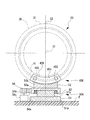
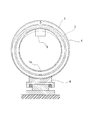
- FIG. 6 is a front view showing a drive mechanism of the gantry 30 in the radiation treatment apparatus 20 in the third embodiment
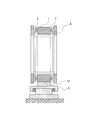
- FIG. 7 is a side sectional view showing the drive mechanism of the gantry 30.
- the radiation treatment apparatus 20 in this embodiment includes a vertical rotation mechanism 40C for rotatably supporting the gantry 30 around a horizontal central axis C1 extending in the horizontal direction, the gantry 30, and the vertical And a horizontal pivoting drive mechanism (pivotal mechanism) 50C for pivotably supporting the pivoting mechanism 40C around a vertical central axis C2 extending in the vertical direction.
- the vertical turning mechanism 40C includes a gantry rail 41 and sliding members (first sliding member, second sliding member) 45D for guiding the gantry rail 41 in a slidable manner.
- the sliding members 45D, 45D are provided at both end portions in the circumferential direction of the support 42C on the side surfaces 42s, 42s of the support 42C.
- the support 42 ⁇ / b> C has an arc shape provided in a range below the horizontal central axis C ⁇ b> 1 of the gantry 30.
- support legs 48 extending vertically downward are integrally formed at both end portions in the circumferential direction of the support 42C.
- the gantry rail 41 extends obliquely in a portion supported by the sliding members 45D, 45D. That is, the sliding members 45D, 45D, like the sliding members 45C, 45C of the second embodiment, have the function of receiving the vertical load of the gantry 30 and the function of restraining the horizontal displacement of the gantry 30. ,have. In other words, the sliding members 45D, 45D have the functions of both the one sliding member and the second sliding member of the present invention.
- the horizontal turning drive mechanism 50C includes a base 56 installed on the floor surface F, a turning rail 57, a turning guide 59, and a drive source 60.
- the swing rail 57 is provided on the base 56, and is provided in an annular shape that is continuous in the circumferential direction about the vertical central axis C2.
- An opening 56 a is formed in the base 56 on the inner circumferential side of the turning rail 57.
- a housing portion 58 is formed on the inner peripheral side of the swing rail 57 in the base 56 by the base 56 and the floor surface F. At least a portion of the lower end portion of the gantry 30 and the support 42C is accommodated in the accommodating portion 58.
- a recess in the floor surface F a deeper accommodation portion 58 can be formed. In this case, more gantry 30 and support 42C can be accommodated in the accommodating portion 58.
- the pivot guide 59 is slidable along the pivot rail 57.
- the pivot guide 59 is provided at the lower end of the support leg 48 of the support 42C.
- At least two turning guides 59 are provided on the lower surface of the support 42C at intervals in the circumferential direction of the turning rail 57.
- the support 42C is pivotably supported around the vertical central axis C2.
- each sliding member 45D is disposed in the vertically upper range of the turning guide 59 and the support leg 48.
- the drive source 60 is provided integrally with, for example, the support 42C.
- the drive source 60 includes an arc-shaped gear 60 a concentrically provided with the turning rail 57, and a motor 60 c having a drive gear 60 b meshing with the gear 60 a.
- the support 42C and the gantry 30 can be pivoted around the vertical central axis C2 integrally with the arc-shaped gear 60a.
- the accommodation portion 58 is formed on the inner peripheral side of the base 56 and the pivot rail 57, so that at least the lowermost portion of the gantry 30 and the support 42C can be accommodated.
- the height of the radiation treatment apparatus 20 can be reduced.
- the motor 60c constituting the drive source 60 can be provided integrally with the base 56, there is no need to separately perform foundation work on the installation surface to provide the motor 60c, and installation and construction can be easily performed. it can.
- the load in the vertical direction of the gantry 30 supported by the slide members 45D, 45D by disposing the slide members 45D, 45D vertically above the swivel guide 59 and the support leg 48, the swing guide 59 and the support legs It can transmit efficiently to the floor surface F via the pivot rail 57 and the base 56.
- the support 42C is provided with the slide members 45D, 45D provided with the gantry rail 41 on the annular gantry 30 side and guiding the gantry rail 41 to the support 42C. There is no need to make it annular. As a result, the size and weight of the support 42C can be reduced.
- the sliding members 45D, 45D receive the load in the vertical direction of the gantry 30, and restrain the displacement of the gantry 30 in the horizontal direction, whereby the gantry 30 can be stably rotated. Furthermore, the sliding members 45D, 45D are arranged in line symmetry with respect to the vertical central axis C2 passing through the central axis of the gantry 30, so that the gantry 30 can be stably and rotatably supported.
- the present invention is not limited to the above-described embodiments, and includes the above-described embodiments with various modifications added thereto, without departing from the spirit of the present invention. That is, the specific shape, configuration, and the like described in the embodiment are merely examples, and can be changed as appropriate.
- two slide members 45C, 45C and two slide members 45D, 45D are provided in the second and third embodiments.
- the arrangement of the sliding members 45C, 45C and the sliding members 45D, 45D is not limited to the arrangement that is line symmetrical with respect to the vertical central axis C2 of the gantry 30, but may be arranged asymmetrically. Further, between the two sliding members 45C, 45C and the two sliding members 45D, 45D described above, as in the first embodiment, the gantry is positioned at the bottom of the support 42B. A sliding member 45A that receives a load of 30 in the vertical direction may be provided.
- the sliding members 45A and 45C are disposed in the vertically upper range of the support shaft 51b and the rotation shaft 53b of the horizontal turning drive mechanism 50A.
- the present invention is not limited to this configuration.
- the slide members 45A and 45C can be disposed outside the vertically upper range of the support shaft 51b of the horizontal turning drive mechanism 50A and the rotation shaft 53b.
- a plurality of sliding members 45A, 45C may be provided in the range vertically above the rotation shaft portion 53b.
- the plurality of sliding members 45A, 45C may be arranged symmetrically so as to sandwich the vertically upper position of the rotation shaft portion 53b.
- the sliding members 45D, 45D are disposed vertically above the pivot guide 59 and the support leg 48.
- a plurality of sliding members 45D may be provided in the range vertically above the pivot guide 59 and the support leg 48.
- the plurality of sliding members 45D may be arranged symmetrically so as to sandwich the vertically upper position of the turning guide 59 and the support leg 48.
- the base 56 is provided with the turning rail 57 and the support 42C is provided with the turning guide 59.
- the pivot rail 57 may be provided on the support 42C
- the pivot guide 59 may be provided on the base 56.
- the supports 42A, 42B, 42C are not limited to the arc shape.
- the slide members 45A to 45D may have other shapes, for example, a V shape, a concave shape, or the like, as long as the slide members 45A to 45D can be supported at predetermined positions.
- support posts in the form of columns for supporting the respective slide members 45A to 45D may be provided individually.
- the supports 42A, 42B, 42C may be formed in an annular shape for the purpose of providing various devices and the like.
Landscapes
- Health & Medical Sciences (AREA)
- Engineering & Computer Science (AREA)
- Biomedical Technology (AREA)
- Pathology (AREA)
- Nuclear Medicine, Radiotherapy & Molecular Imaging (AREA)
- Radiology & Medical Imaging (AREA)
- Life Sciences & Earth Sciences (AREA)
- Animal Behavior & Ethology (AREA)
- General Health & Medical Sciences (AREA)
- Public Health (AREA)
- Veterinary Medicine (AREA)
- Radiation-Therapy Devices (AREA)
Abstract
Priority Applications (4)
| Application Number | Priority Date | Filing Date | Title |
|---|---|---|---|
| US15/111,371 US10143860B2 (en) | 2014-01-21 | 2014-01-21 | Radiation therapy apparatus |
| EP14879326.8A EP3097951B1 (fr) | 2014-01-21 | 2014-01-21 | Appareil de radiothérapie |
| PCT/JP2014/051090 WO2015111132A1 (fr) | 2014-01-21 | 2014-01-21 | Appareil de radiothérapie |
| JP2015558621A JP6114409B2 (ja) | 2014-01-21 | 2014-01-21 | 放射線治療装置 |
Applications Claiming Priority (1)
| Application Number | Priority Date | Filing Date | Title |
|---|---|---|---|
| PCT/JP2014/051090 WO2015111132A1 (fr) | 2014-01-21 | 2014-01-21 | Appareil de radiothérapie |
Publications (1)
| Publication Number | Publication Date |
|---|---|
| WO2015111132A1 true WO2015111132A1 (fr) | 2015-07-30 |
Family
ID=53680968
Family Applications (1)
| Application Number | Title | Priority Date | Filing Date |
|---|---|---|---|
| PCT/JP2014/051090 Ceased WO2015111132A1 (fr) | 2014-01-21 | 2014-01-21 | Appareil de radiothérapie |
Country Status (4)
| Country | Link |
|---|---|
| US (1) | US10143860B2 (fr) |
| EP (1) | EP3097951B1 (fr) |
| JP (1) | JP6114409B2 (fr) |
| WO (1) | WO2015111132A1 (fr) |
Families Citing this family (4)
| Publication number | Priority date | Publication date | Assignee | Title |
|---|---|---|---|---|
| CN114306957B (zh) * | 2017-02-13 | 2024-09-10 | 西安大医集团股份有限公司 | 一种放射治疗设备 |
| CN109200485B (zh) * | 2018-09-20 | 2024-02-02 | 成都真实维度科技有限公司 | 一种用于多点共面激光引导照射的角度偏移装置 |
| CN113491842A (zh) * | 2020-03-20 | 2021-10-12 | 西安大医集团股份有限公司 | 一种旋转机架及放射治疗设备 |
| CA3198728A1 (fr) | 2020-10-16 | 2022-04-21 | The Johns Hopkins University | Irradiateur d'enceinte a rayons x a debit de dose ultra eleve |
Citations (7)
| Publication number | Priority date | Publication date | Assignee | Title |
|---|---|---|---|---|
| JPH09508550A (ja) * | 1994-02-08 | 1997-09-02 | アナロジック コーポレーション | X線断層撮影走査装置 |
| JPH09304303A (ja) * | 1996-05-15 | 1997-11-28 | Hitachi Eng & Services Co Ltd | 可搬型x線ct装置 |
| JP2002325854A (ja) * | 2001-05-01 | 2002-11-12 | Hitachi Medical Corp | 放射線治療装置 |
| JP2006021046A (ja) * | 2005-07-05 | 2006-01-26 | Mitsubishi Heavy Ind Ltd | 放射線治療装置 |
| JP2008200091A (ja) * | 2007-02-16 | 2008-09-04 | Mitsubishi Heavy Ind Ltd | 放射線治療装置 |
| JP4228019B2 (ja) | 2007-02-16 | 2009-02-25 | 三菱重工業株式会社 | 医療装置 |
| JP2012125561A (ja) * | 2010-12-10 | 2012-07-05 | Ge Medical Systems Global Technology Co Llc | Ctスキャンフレームに用いられる自己調整軸受 |
Family Cites Families (4)
| Publication number | Priority date | Publication date | Assignee | Title |
|---|---|---|---|---|
| DE2608461A1 (de) * | 1976-03-01 | 1977-09-15 | Siemens Ag | Roentgenuntersuchungsgeraet |
| DE19947809A1 (de) * | 1999-10-05 | 2001-04-12 | Philips Corp Intellectual Pty | C-Bogen-Röntgeneinrichtung |
| CN100398066C (zh) | 2002-03-13 | 2008-07-02 | 分离成像有限责任公司 | 准同步多平面x射线成像的系统和方法 |
| JP5909275B2 (ja) | 2012-02-29 | 2016-04-26 | 三菱重工業株式会社 | X線治療システム及び光子検出方法 |
-
2014
- 2014-01-21 WO PCT/JP2014/051090 patent/WO2015111132A1/fr not_active Ceased
- 2014-01-21 JP JP2015558621A patent/JP6114409B2/ja active Active
- 2014-01-21 US US15/111,371 patent/US10143860B2/en active Active
- 2014-01-21 EP EP14879326.8A patent/EP3097951B1/fr active Active
Patent Citations (7)
| Publication number | Priority date | Publication date | Assignee | Title |
|---|---|---|---|---|
| JPH09508550A (ja) * | 1994-02-08 | 1997-09-02 | アナロジック コーポレーション | X線断層撮影走査装置 |
| JPH09304303A (ja) * | 1996-05-15 | 1997-11-28 | Hitachi Eng & Services Co Ltd | 可搬型x線ct装置 |
| JP2002325854A (ja) * | 2001-05-01 | 2002-11-12 | Hitachi Medical Corp | 放射線治療装置 |
| JP2006021046A (ja) * | 2005-07-05 | 2006-01-26 | Mitsubishi Heavy Ind Ltd | 放射線治療装置 |
| JP2008200091A (ja) * | 2007-02-16 | 2008-09-04 | Mitsubishi Heavy Ind Ltd | 放射線治療装置 |
| JP4228019B2 (ja) | 2007-02-16 | 2009-02-25 | 三菱重工業株式会社 | 医療装置 |
| JP2012125561A (ja) * | 2010-12-10 | 2012-07-05 | Ge Medical Systems Global Technology Co Llc | Ctスキャンフレームに用いられる自己調整軸受 |
Also Published As
| Publication number | Publication date |
|---|---|
| EP3097951A1 (fr) | 2016-11-30 |
| EP3097951A4 (fr) | 2017-02-22 |
| JP6114409B2 (ja) | 2017-04-12 |
| JPWO2015111132A1 (ja) | 2017-03-23 |
| US20160332001A1 (en) | 2016-11-17 |
| EP3097951B1 (fr) | 2018-07-25 |
| US10143860B2 (en) | 2018-12-04 |
Similar Documents
| Publication | Publication Date | Title |
|---|---|---|
| JP4228019B2 (ja) | 医療装置 | |
| JP4936924B2 (ja) | 粒子線照射システム | |
| JP4228018B2 (ja) | 医療装置 | |
| CN102548612B (zh) | 具有可旋转的治疗头的直线运动学系统 | |
| CN107441634B (zh) | 放射线摄影装置及粒子线治疗系统 | |
| JP4695231B2 (ja) | 治療台システム | |
| CN104784831B (zh) | 一种可实现全轨迹放射治疗设备 | |
| CN203379504U (zh) | 一种适用于固定式强子束的360度治疗装置 | |
| JP6114409B2 (ja) | 放射線治療装置 | |
| US20230111290A1 (en) | Radiotherapy apparatus for positioning a subject | |
| JP2013169289A (ja) | 患者傾動装置付きカウチ | |
| CN110234396B (zh) | 一种放射治疗设备 | |
| JP4996450B2 (ja) | 絞り装置及び絞り装置を用いた放射線治療装置 | |
| CA2528800A1 (fr) | Dispositif de positionnement et de fixation stereotactique du haut du corps | |
| JP5829162B2 (ja) | X線撮影装置 | |
| KR20170101725A (ko) | 유지 보수가 편리한 듀얼 헤드 타입의 방사선 치료장치 | |
| CN102266644B (zh) | 辐射装置 | |
| CN1870940A (zh) | 通过电离辐射用于治疗的仪器 | |
| JPH1094617A (ja) | 放射線治療用の加速器照射装置 | |
| JP2002325854A (ja) | 放射線治療装置 | |
| US10653895B2 (en) | Radiotherapy apparatus |
Legal Events
| Date | Code | Title | Description |
|---|---|---|---|
| 121 | Ep: the epo has been informed by wipo that ep was designated in this application |
Ref document number: 14879326 Country of ref document: EP Kind code of ref document: A1 |
|
| ENP | Entry into the national phase |
Ref document number: 2015558621 Country of ref document: JP Kind code of ref document: A |
|
| WWE | Wipo information: entry into national phase |
Ref document number: 15111371 Country of ref document: US |
|
| REEP | Request for entry into the european phase |
Ref document number: 2014879326 Country of ref document: EP |
|
| WWE | Wipo information: entry into national phase |
Ref document number: 2014879326 Country of ref document: EP |
|
| NENP | Non-entry into the national phase |
Ref country code: DE |