WO2015111143A1 - Dispositif de détection ultrasonore de défaut pour inspection de soudures, procédé de détection ultrasonore de défaut pour inspection de soudures et procédé de fabrication de structure de véhicule ferroviaire les utilisant - Google Patents
Dispositif de détection ultrasonore de défaut pour inspection de soudures, procédé de détection ultrasonore de défaut pour inspection de soudures et procédé de fabrication de structure de véhicule ferroviaire les utilisant Download PDFInfo
- Publication number
- WO2015111143A1 WO2015111143A1 PCT/JP2014/051179 JP2014051179W WO2015111143A1 WO 2015111143 A1 WO2015111143 A1 WO 2015111143A1 JP 2014051179 W JP2014051179 W JP 2014051179W WO 2015111143 A1 WO2015111143 A1 WO 2015111143A1
- Authority
- WO
- WIPO (PCT)
- Prior art keywords
- ultrasonic
- display
- echo
- flaw detection
- defect
- Prior art date
- Legal status (The legal status is an assumption and is not a legal conclusion. Google has not performed a legal analysis and makes no representation as to the accuracy of the status listed.)
- Ceased
Links
Images


Classifications
-
- G—PHYSICS
- G01—MEASURING; TESTING
- G01N—INVESTIGATING OR ANALYSING MATERIALS BY DETERMINING THEIR CHEMICAL OR PHYSICAL PROPERTIES
- G01N29/00—Investigating or analysing materials by the use of ultrasonic, sonic or infrasonic waves; Visualisation of the interior of objects by transmitting ultrasonic or sonic waves through the object
- G01N29/44—Processing the detected response signal, e.g. electronic circuits specially adapted therefor
- G01N29/4409—Processing the detected response signal, e.g. electronic circuits specially adapted therefor by comparison
- G01N29/4427—Processing the detected response signal, e.g. electronic circuits specially adapted therefor by comparison with stored values, e.g. threshold values
-
- G—PHYSICS
- G01—MEASURING; TESTING
- G01N—INVESTIGATING OR ANALYSING MATERIALS BY DETERMINING THEIR CHEMICAL OR PHYSICAL PROPERTIES
- G01N29/00—Investigating or analysing materials by the use of ultrasonic, sonic or infrasonic waves; Visualisation of the interior of objects by transmitting ultrasonic or sonic waves through the object
- G01N29/04—Analysing solids
- G01N29/11—Analysing solids by measuring attenuation of acoustic waves
-
- G—PHYSICS
- G01—MEASURING; TESTING
- G01N—INVESTIGATING OR ANALYSING MATERIALS BY DETERMINING THEIR CHEMICAL OR PHYSICAL PROPERTIES
- G01N2291/00—Indexing codes associated with group G01N29/00
- G01N2291/04—Wave modes and trajectories
- G01N2291/044—Internal reflections (echoes), e.g. on walls or defects
-
- G—PHYSICS
- G01—MEASURING; TESTING
- G01N—INVESTIGATING OR ANALYSING MATERIALS BY DETERMINING THEIR CHEMICAL OR PHYSICAL PROPERTIES
- G01N2291/00—Indexing codes associated with group G01N29/00
- G01N2291/10—Number of transducers
- G01N2291/106—Number of transducers one or more transducer arrays
-
- G—PHYSICS
- G01—MEASURING; TESTING
- G01N—INVESTIGATING OR ANALYSING MATERIALS BY DETERMINING THEIR CHEMICAL OR PHYSICAL PROPERTIES
- G01N2291/00—Indexing codes associated with group G01N29/00
- G01N2291/26—Scanned objects
- G01N2291/267—Welds
Definitions
- the present invention relates to an ultrasonic flaw detection apparatus and an ultrasonic flaw detection method for flaws, cracks, and weld defects that occur in welds that join plate materials.
- Welding is indispensable for manufacturing large structures, but welding defects rarely occur at the weld due to welding. Therefore, the quality of a welded part is guaranteed by performing an appropriate nondestructive inspection on the welded part.
- a general nondestructive inspection method for a welded portion an ultrasonic flaw detection method or a radiation inspection method can be cited.
- the ultrasonic flaw detection method is widely used because of the simplicity of the apparatus and the absence of operations such as shielding necessary for radiation inspection.
- Patent Document 1 discloses an ultrasonic flaw detection method for a welded portion in which plate materials are joined to each other.
- two oblique probes are arranged on one surface of a welded portion so as not to be on the same straight line, and the ultrasonic probe is scanned back and forth in the direction orthogonal to the welded portion. Then, the defect generated in the thickness direction is detected by adjusting the incident angle of the ultrasonic wave to the weld line and the distance to the weld line.
- Patent Document 2 discloses an aperture synthesis processing technique using a phased array. According to the invention disclosed in Patent Literature 2, the amplitude is corrected by multiplying the waveform signal obtained by the receiving element of the phased array by the inverse of the influence function, aperture synthesis processing is performed on the corrected signal, and an inspection image is obtained. By constructing, the defect can be detected with the same sensitivity regardless of the position in the thickness direction.
- the ultrasonic probe has been manually moved in a zigzag manner in the longitudinal direction of the welded part, the direction parallel to the weld line, and in the direction intersecting the welded line, to detect the welded part. . Since a convex weld surplus is usually generated on the surface of the welded portion, the weld surplus is cut with a grinder or the like, and the surface of the welded portion is finished to make a flaw detection. In this method, since it is necessary to remove the welding surplus before the inspection, a technique for performing the welding inspection at a high speed without performing this processing is desired.
- the railway vehicle structure has a total length of 20 to 25 m, and its weld line length is very long.
- the railway vehicle structure is composed of an aluminum alloy panel, and the thickness of the panel member is as thin as about 3 mm. Therefore, in order to inspect with the welding surplus remaining at the weld, it is necessary to increase the refraction angle of the ultrasonic wave for irradiation.
- a signal from a reflection source such as a flaw (hereinafter referred to as an echo) is displayed on the high refraction angle side, that is, at a shallow position near the surface, and the actual flaw depth position. Cannot be evaluated correctly, affecting the removal and repair work of weld defects.
- Patent Document 2 can perform signal evaluation with the same sensitivity in the depth direction, it does not take into consideration correction means for distortion in the depth position of an image that occurs in the case of an inspection target with a thin member plate thickness. Therefore, there is a risk that accurate instructions for defect removal and repair cannot be given.
- the present invention provides an ultrasonic that can inspect the presence or absence of a defect in the welded portion only by parallel movement along the longitudinal direction of the welded portion without performing forward or backward scanning of the ultrasonic probe in the orthogonal direction of the welded portion.
- an object is to correct and display an echo of a reflection source such as a flaw at a correct position.
- an ultrasonic array sensor that transmits and receives ultrasonic waves to the welded part, and the ultrasonic array sensor
- An ultrasonic array sensor holder that moves the ultrasonic wave along the longitudinal direction of the weld
- an ultrasonic flaw detector that converts ultrasonic waves received by the ultrasonic array sensor into echoes, and the weld using the echoes
- a flaw detection controller for detecting defects and a display for displaying a measurement result, wherein the flaw detection controller converts the display position based on the display refraction angle and display depth of the ultrasonic echo recorded in the flaw detection controller.
- a display position correction unit that corrects the display position of the measurement image according to the equation, a reference echo intensity table based on the display refraction angle and display depth of the ultrasonic echo recorded in the flaw detection controller, and the ecology of the extracted defect echo Characterized in that it comprises a defect determination unit which compares the intensity and determines defective.
- an ultrasonic wave capable of inspecting the presence or absence of a defect in a welded part only by parallel movement along the longitudinal direction of the welded part without moving the ultrasonic probe forward or backward in the welded part orthogonal direction.
- the flaw detection apparatus or the flaw detection method it is possible to correct and display the echo of the reflection source such as a flaw at a correct position.
- 1 is a system configuration diagram of an ultrasonic flaw detector according to an embodiment. It is a mimetic diagram of a railroad car structure which is an application object of an ultrasonic flaw detector of an example. It is a schematic diagram of the panel junction part of a railway vehicle structure. It is a schematic diagram which shows arrangement
- the longitudinal direction of the weld line which is the center line of the welded portion, is the Z direction
- the direction orthogonal to the longitudinal direction of the weld line is the X direction
- the thickness of the plate to be inspected Let the direction be the Y direction.
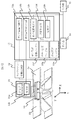
- FIG. 1 is a system configuration diagram of the ultrasonic flaw detector according to the present embodiment.
- the ultrasonic flaw detection apparatus according to the present embodiment includes an ultrasonic sensor unit 10 including an ultrasonic array sensor that transmits and receives ultrasonic waves in contact with an object to be inspected, and transmits or receives analog echoes.
- An ultrasonic flaw detector 11 that controls the array sensor, a sensor unit movement controller 12 that performs movement control and movement amount measurement of the ultrasonic sensor unit 10, and an ultrasonic flaw detector 11 and a sensor that collectively control the entire ultrasonic inspection.
- a flaw detection controller 13 that processes data in the unit movement controller 12 to create an inspection image, a display 14 that displays an inspection image as an inspection result, and an input device 15 that receives input of various information.
- the ultrasonic flaw detector 11, the sensor unit movement controller 12, and the flaw detector controller 13 are an analog / digital conversion board that digitizes analog signals, an amplifier that amplifies AD-converted digital signals, and digitalized echoes.
- it includes a processor that executes various processes, a memory that stores software executed by the processor, a secondary storage device, and the like.
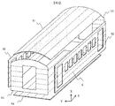
- FIG. 2 shows a schematic diagram of the railway vehicle structure.
- a railway vehicle structure is produced by installing a roof structure 51, a side structure 52, and a wife structure 53 on a frame 54 and welding the structures together. Many of these weld lines exist as shown by the alternate long and short dash line in FIG.
- the panel length is 20 m to 25 m, and the weld line reaches a maximum length of 25 m. Therefore, the inspection of the railway vehicle structure must be a measurement method corresponding to the long length, and the movement of the ultrasonic array sensor Indispensable.
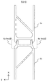
- the panel constituting the structure shown in FIG. 3 has a structure in which the mold members 5a and 5b are fitted together, and is produced by welding the fitting part 6a (inside the broken line in FIG. 3).
- the material of the mold is generally an aluminum alloy material, and the plate thickness is about 3 mm, which is very thin.
- the structure as shown in FIG. 3 is called a double skin structure, which contributes to weight reduction of the railway vehicle.
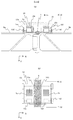
- FIG. 4 shows a configuration of the ultrasonic sensor unit 10 arranged on the structure in which the mold materials 5 a and 5 b are joined by the welded portion 6.
- the ultrasonic sensor unit 10 includes an ultrasonic array sensor, a motor, casings 10a and 10b that store movement amount measuring instruments, an ultrasonic array sensor holder 10c that holds the ultrasonic array sensor, and the ultrasonic sensor unit 10 at the welded portion.
- a pair of ultrasonic array sensors 1a and 1b are stored in the casings 10a and 10b, and are installed so as to straddle the welded portion 6 on the upper surface of the mold material 5a or 5b. To do.
- a contact medium such as water, oil or glycerin paste is applied to the ultrasonic array sensor installation surface.
- the ultrasonic array sensor holder 10c measures the pair of ultrasonic array sensors 1a and 1b while maintaining a certain distance by fixing the casings 10a and 10b with screws or the like.
- the ultrasonic sensor unit 10 is self-propelled and is provided with a probe moving mechanism for moving along the longitudinal direction of the welded part of the inspection object.
- a tire 10d and a motor 10e for driving the tire are installed and can be moved in parallel with respect to the longitudinal direction of the welded portion 6 (Z direction in FIG. 4). If the motor 10e is installed for at least one of the four tires 10d, the ultrasonic array sensor holder 10c can be moved.
- a movement amount measuring device 10f is connected to at least one of the four tires 10d, and the distance traveled by the ultrasonic sensor unit 10 is measured from the rotation amount of the tire.
- the ultrasonic flaw detector 11 is connected to the ultrasonic array sensors 1a and 1b and controls transmission of ultrasonic waves and reception of reflected echoes from defects.
- the received echo is converted into an electric signal, digitized and recorded, further converted into image information, and sent to the flaw detection controller 13.
- the transmitter 11a and the receiver 11b of the ultrasonic flaw detector 11 give a delay time to the transmission and reception of the ultrasonic array transducers of the ultrasonic array sensors 1a and 1b, and determine the ultrasonic transmission direction and focal position. adjust.
- the sensor unit movement controller 12 controls the position of the ultrasonic array sensors 1a and 1b by controlling the movement of the ultrasonic sensor unit 10 by calculating the movement distance of the movement amount measuring device 10f and driving control of the motor 10e.
- the calculation result of the moving distance is transmitted to the flaw detection controller 13, and is used for the flaw detection result display and the defect occurrence range recording in the flaw detection controller 13.
- the ultrasonic sensor unit 10 can be self-propelled by a command from the sensor unit movement controller 12.
- the flaw detection controller 13 controls the ultrasonic flaw detector 11 and the sensor unit movement controller 12.
- a sensor position evaluation unit 13a As components, a sensor position evaluation unit 13a, an ultrasonic signal evaluation unit 13b, a display position correction unit 13c, a defect determination unit 13d, a drawing unit 13e, a display position conversion table 13f, an echo intensity table 13g, and a shape figure table 13h are required. is there.
- the sensor position evaluation unit 13a issues a movement instruction in the sensor unit movement controller 12, receives movement distance information, and records position information of the ultrasonic array sensors 1a and 1b.
- the ultrasonic signal evaluator 13b sends an ultrasonic wave transmission instruction from the ultrasonic flaw detector 11 and records information such as a received wave and measurement conditions at that time.
- the display position correction unit 13c When there is distortion in the echo display position of the inspection image based on the ultrasonic signal and the measurement conditions in the ultrasonic signal evaluation unit 13b, the display position correction unit 13c performs image correction by correcting the coordinates of the echo position to the actual position. Perform reconfiguration.
- the defect determination unit 13d extracts a defect signal from the reconstructed image information whose position is corrected by the display position correction unit 13c, and performs defect determination based on the actual defect position and echo intensity of the detection signal.
- the drawing unit 13e creates an inspection result image based on the sensor position evaluation unit 13a, the display position correction unit 13c, and the defect determination unit 13d, and sends the inspection result image to the display unit 14.
- the display position conversion table 13f stores reference data when performing the image position correction processing performed by the display position correction unit 13c.
- the echo intensity table 13g stores reference data when performing the defect determination process performed by the defect determination unit 13d.
- the shape figure table 13h has CAD information, which is shape information of the inspection target.
- the shape information is not limited to CAD, but may be information in an arbitrary format. The shape information is displayed together with the flaw detection result on the display 14 and used as reference data when setting the inspection evaluation area.
- the display 14 displays the positions of the ultrasonic array sensors 1a and 1b, the flaw detection results, and the like based on the inspection result output information from the flaw detection controller 13.
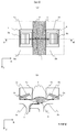
- FIG. 5 shows the configuration of the ultrasonic array sensor of this example.
- the ultrasonic array sensor used in the ultrasonic inspection a single transducer type ultrasonic array sensor is used, and is arranged on the surface of the plate material so as to face each other with the welded portion 6 interposed therebetween as shown in FIG.
- FIG. 5A is a top view arrangement of the ultrasonic array sensors 1a and 1b with respect to the direction intersecting the weld line
- FIG. 5B is a cross-sectional view of the ultrasonic array sensor with respect to the direction intersecting the weld line (FIG. 5).
- 5 (a) shows a BB ′ cross section).
- the mold members 5a and 5b are joined by the welded portion 6, and the cross section of the welded portion 6 has a shape similar to a sector shape with the welding surplus on the upper side (the mounting surface side of the ultrasonic array sensor).
- the purpose is to detect a defect generated in the welded portion.
- the ultrasonic array sensor is arranged so that the ultrasonic wave is incident on the defect from an oblique direction.
- ultrasonic array transducers 3a and 3b which are aggregates of elements that transmit and receive ultrasonic waves, are installed inside the ultrasonic array sensors 1a and 1b.
- the ultrasonic array transducers 3a and 3b are composed of a plurality of arranged transducers, and the ultrasonic wave transmission direction and the focal position can be adjusted by electronic scanning for adjusting the voltage time applied to the transducers.
- a resin wedge 4 is installed at the lower part of the vibrator, and the ultrasonic array vibrator is tilted.
- the wedge 4 is built in the ultrasonic array sensor to reduce the size.
- the ultrasonic array transducer receives the transmitted ultrasonic waves reflected by the above-mentioned defects or feature points such as the shape corners of the object to be inspected, the difference between the reception times of each transducer and the sound velocity in the test material The position of the reflection source can be specified.
- Such an ultrasonic transmission and reception method is called a phased array method.
- Ultrasonic waves can be scanned by programming and changing the applied voltage time described above. Thereby, the inspection range can be shortened because a wide range can be inspected by minimizing the moving range of the ultrasonic array sensor.
- the electronic scanning conditions of the ultrasonic array sensor can be optimized and the optimum scanning conditions that can inspect the defects assumed in the welded portion can be determined, so that the inspection time can be shortened.
- points O 1 and O 2 are intersections between a perpendicular drawn from the transducer that transmits the ultrasonic wave to the surface of the inspection object and the surface of the inspection object, and are sector-shaped obtained by the sector scan method. This is the reference position of the ultrasonic image.
- the ultrasonic array sensors 1a and 1b perform measurement independently. For this reason, only the operation of the ultrasonic array sensor 1a is described, but the operation of the ultrasonic array sensor 1b is the same as described below.
- transmitting an ultrasonic wave 2 from the ultrasonic array transducer 3a receiving reflected ultrasonic waves at defect D 1 (the echo) the ultrasonic array transducer 3a
- the presence or absence of a defect is determined by analyzing and imaging the reflected echo obtained from the received and received ultrasonic waves.
- the member plate thickness of the mold is assumed to be t. Because welding defects easily occur in the weld root, here was FIG assuming a case of generating a defect D 1 in the weld root.
- the measurement image at this time is shown in FIG.
- a sector scan image in the above testing method in the measurement using an ultrasonic array sensor 1a, and transmitting ultrasonic waves from the ultrasonic array transducer 3a, ultrasonic array transducer and reflected ultrasonic waves at defect D 1
- the flaw detection result by the ultrasonic wave received by the child 3a is displayed.
- the position of the ultrasonic array probe received by the top left corner O 1 is shown
- the X direction represents the horizontal distance from the ultrasonic array sensor to the reflection source
- the Y direction The vertical direction shown indicates the depth from the ultrasonic array sensor to the reflection source.
- the sector scan image clearly shows the positional relationship between the ultrasonic array sensor and the reflection source.
- E 1 is an ultrasonic echo caused by a defect
- no E 1 echo appears in a portion where there is no defect.
- a region B indicated by a dotted line is a defect evaluation range. In the setting of this region, the position in the X direction corresponds to the both toe positions of the welding surplus, and the position in the Y direction is set slightly larger than the member plate thickness t of the mold material from the surface.
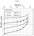
- the defect echo E 1 is displayed shallower than the original defect depth. That is, assuming that the defect position in the substance is t, the depth of the defect echo displayed in the sector scan image is t 1 (t 1 ⁇ t). This is because, when an image is formed by the ultrasonic flaw detector 11, the difference in ultrasonic arrival time when the ultrasonic array transducer generates a composite wavefront of the received signal is small at an angle where the refraction angle ⁇ is large. This is due to an increase in spatial resolution error in the refraction angle region. The result of measuring the characteristics is shown in FIG.
- the vertical axis represents the display defect depth t 1
- the horizontal axis represents the refraction angle ⁇ .
- the four lines in the figure are measurement data of the display position of the reference defect having a depth of 2 mm to 5 mm. From the figure, it can be confirmed that the display defect depth t 1 decreases as the refraction angle ⁇ increases. For example, when a reference defect having a depth of 5 mm is measured at a refraction angle of 82 °, it is displayed at a depth of 2.5 mm.
- a coordinate conversion correction table of refraction angles and depth positions is created in advance, and coordinate conversion is performed on the acquired echo or the entire image and displayed as a corrected image.
- the substantial defect depth t is created as a coordinate conversion correction formula (formula (1)) between the refraction angle ⁇ and the defect display depth position t 1 .
- a, b, c, and d are constants based on previously measured data
- f and g are functions.
- the coordinate conversion correction formula data of the refraction angle and the depth position is created in advance by measurement by experiment or prediction by numerical analysis, and is recorded in the display position conversion table 13f.
- FIG. 8 is created based on the measurement data of FIG. 7 for data with an entity defect depth t of 2 mm to 5 mm, but for the data with an entity defect depth t of 1 mm, the measurement data and numerical analysis are performed. Is the predicted value.
- the ultrasonic array sensor cannot sufficiently approach the defect, it is necessary to measure at a high refraction angle, for example, in the range of 65 ° to 80 °. In many cases, you will not get. Therefore, the distortion correction of the defect echo image having a high refraction angle and a shallow portion shown in the present embodiment is very useful.
- the defect echo can be displayed at the echo position E in FIG. 6B, and the position of the defect can be correctly determined.
- defect it is determined whether the defect develops during the service period and the vehicle is defective. When it is considered that a defect will occur in the vehicle, it is judged that repair is necessary, and repairs such as defect removal and welding re-construction are performed. Therefore, it is necessary to accurately grasp the position and size of the detected defect.
- the defect position can be correctly evaluated by the depth position correction by the coordinate conversion described above. Therefore, a method for accurately grasping the size of the defect is necessary. Therefore, an allowable defect size is set based on the load stress and the importance of the member according to the load state of the inspection target part at the time of vehicle design.
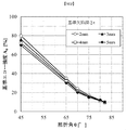
- an echo intensity table for a reference defect as shown in FIG. 9 is created as a criterion.
- This table is stored in the echo intensity table 13g in the flaw detection controller 13.
- FIG. 9 will be described.
- the vertical axis represents the echo intensity A 0 of the reference defect measured by experiment, and the horizontal axis represents the refraction angle ⁇ of the display image.
- the reference defect is measured for a plurality of reference defects having different depths so as to cover the depth range to be measured.
- measurement data of a reference defect having a depth of 2 mm to 5 mm is shown. Describe how to use this table.
- the defect depth t, the refraction angle ⁇ , and the echo intensity A of the substance are extracted from the defect echo of the image subjected to the depth position correction by the coordinate transformation described above.
- the echo intensity A 0 of the reference defect with respect to the defect depth t and the refraction angle ⁇ is obtained from the echo intensity table.
- the determination information is displayed together with the inspection image of the display.
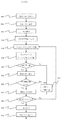
- FIG. 10 is a flowchart showing the contents of control processing in the ultrasonic flaw detector according to this embodiment. This control process is performed based on a program stored in advance in internal memories of the ultrasonic flaw detector 11, the sensor unit movement controller 12, and the flaw detector 13.
- inspection is performed after the template panel temporary assembly in step 500 and the template panel welding in step 600 are performed.
- appropriate inspection conditions considering the state of the inspection section (for example, plate material material, plate thickness, weld groove shape, etc.) are set as follows: ultrasonic flaw detector 11, sensor unit movement controller 12 and Set to the flaw detection controller 13.
- the coordinate conversion correction formula data is set in the display position conversion table by the operation of the program stored in the memory of the flaw detection controller 13.
- the defect determination level of the reference defect corresponding to the inspection target part is set in the echo intensity table.
- the movement amount for each flaw detection step of the ultrasonic array sensor is set.
- an inspection evaluation area in the flaw detection controller 13 is set.
- the measurement region of the welded portion is set from the shape information of the mold members 5a and 5b and the dimensional information of the width (X direction distance) of the welded portion 6.
- a defect evaluation range (S in FIG. 6B) based on the width of the weld surplus and the member plate thickness t of the mold material is set, and step 140 is performed for echoes that appear within this defect evaluation range.
- the defect echo candidates are extracted by performing the above process.
- step 120 the ultrasonic sensor unit 10 is moved to the inspection measurement position.
- the ultrasonic sensor unit 10 is aligned with the start position of the inspection object.
- the ultrasonic array sensors 1a and 1b are arranged to face each other so as to sandwich the welded portion.
- the welding unit is translated in the longitudinal direction (Z direction) by the amount of movement for each flaw detection step set in step 100.
- the position information in the sensor unit movement controller 12 is recorded by the sensor position evaluation unit 13 a of the flaw detection controller 13.
- step 130 irradiation and reception of an ultrasonic beam using an ultrasonic array sensor are performed.
- the flaw detection controller 13 transmits a measurement trigger signal to the ultrasonic flaw detector 11.
- the transmitter 11a and the receiver 11b of the ultrasonic flaw detector 11 perform ultrasonic signal transmission and reception processing by the ultrasonic array sensor 1a.
- the ultrasonic array sensor 1b performs transmission and reception processing.
- the received signal is transmitted to the ultrasonic signal evaluation unit 13b of the flaw detection controller 13.
- step 140 a defect signal detection process is performed. From the measurement result of step 130, the ultrasonic signal evaluation unit 13b determines whether there is an echo appearing in the evaluation region set in step 110 based on the inspection data. If there is an echo in the area, it is detected as a defect echo E and the process of step 150 is performed. If no echo exists in the area, it is determined that no repair is necessary because there is no defect, and the process of step 200 is performed.
- the drawing unit 13e accumulates information indicating “no defect” as a defect determination result together with the inspection image, and displays the information on the display 14.
- step 150 the position of the image is corrected.
- the inspection measurement data processed by the ultrasonic signal evaluation unit 13b is sent to the display position correction unit 13c.
- the coordinate transformation correction formula data is read from the display position conversion table 13f, the inspection measurement data is subjected to image position correction processing, and the defect echo E displayed distorted at a high refraction angle is drawn at the actual defect depth.
- step 160 defect determination is performed based on the signal amplitude of the reflected wave.
- the maximum value A of the received wave signal strength in the vicinity of the echo E extracted in step 150 is compared with the threshold value A 0 for determining the received signal strength. If the echo signal intensity exceeds the threshold value A 0 , it is determined that the defect is a harmful defect in structural strength, and the defect determination unit 13 d of the flaw detection controller 13 processes the defect as being present. Therefore, if the received wave amplitude is A ⁇ A 0 in this determination, it is determined that “no repair is necessary”, and the process of step 200 is performed. The process ends when the flaw detection end point is reached. If the received wave amplitude is A ⁇ A 0, it is determined as a defect and the process of step 170 is performed.
- step 170 it is determined that repair is necessary. Based on the determination in step 160, the drawing unit 13e accumulates the information on “repair required” as the defect determination result together with the inspection image and displays it on the display unit 14. Thereafter, the process of step 180 is performed.
- step 180 the ultrasonic array sensor position is determined. If the ultrasonic array sensor has reached the end of the member to be inspected by the processing of the flaw detection controller 13, the inspection is terminated, and the processing in step 190, that is, the inspection is terminated. However, if the ultrasonic array sensor has not reached the end of the member to be inspected, the process proceeds to step 120, and after moving by a specified amount, flaw detection at a new point is repeated. After a series of inspection work is completed and the inspection in step 200 is completed, the defective part is repaired. The repaired portion is inspected again, and after confirming that there is no defect, the structure panel is assembled in step 700 to form a railcar structure on a hexahedron.
- the ultrasonic probe is moved in the direction perpendicular to the longitudinal direction of the weld line, and the ultrasonic array sensor is moved forward or backward along the weld line direction.
- the ultrasonic flaw detection apparatus or flaw detection method that can inspect the presence or absence of defects generated in the welded part only by parallel movement, an apparatus and method that can quickly measure the weld defects even if there is a surplus weld is realized.
- the image (echo) of the reflection source such as flaws is corrected and displayed at the correct position by the correction means for image distortion, and the removal or repair of flaws is instructed accurately.
Landscapes
- Physics & Mathematics (AREA)
- Analytical Chemistry (AREA)
- Health & Medical Sciences (AREA)
- Life Sciences & Earth Sciences (AREA)
- Chemical & Material Sciences (AREA)
- Biochemistry (AREA)
- General Health & Medical Sciences (AREA)
- General Physics & Mathematics (AREA)
- Immunology (AREA)
- Pathology (AREA)
- Signal Processing (AREA)
- Engineering & Computer Science (AREA)
- Acoustics & Sound (AREA)
- Investigating Or Analyzing Materials By The Use Of Ultrasonic Waves (AREA)
Abstract
La présente invention porte sur un dispositif d'inspection par lequel, lors de la réalisation d'une inspection ultrasonore sur un objet qui comprend des éléments de plaque mince et permet de venir près de défauts, des sources de réflexion telles que des rayures peuvent être affichées en des positions correctes. Le dispositif de détection ultrasonore de défaut selon la présente invention, qui est utilisé pour inspecter des soudures entre des éléments, comporte un réseau de capteurs ultrasonores qui émet et reçoit des ultrasons vers et depuis une soudure, un organe de maintien de réseau de capteurs ultrasonores qui déplace ledit réseau de capteurs ultrasonores dans la direction de la longueur de la soudure, un détecteur ultrasonore de défaut qui convertit les ultrasons reçus par le réseau de capteurs ultrasonores en échos, un dispositif de commande de détection de défaut qui utilise lesdits échos pour détecter des défauts dans la soudure, et une unité d'affichage qui affiche des résultats de mesure. Le dispositif de commande de détection de défaut présente ce qui suit : une unité de correction de position d'affichage qui corrige une distorsion dans des images de mesure selon une formule de conversion de position d'affichage basée sur des angles de réfraction d'affichage d'écho ultrasonore et des profondeurs d'affichage enregistrées dans le dispositif de commande de détection de défaut ; une table d'intensité d'écho de référence obtenue à partir des angles de réfraction d'affichage d'écho ultrasonore et des profondeurs d'affichage enregistrées dans le dispositif de commande de détection de défaut ; et une unité d'identification de défaut qui identifie des défauts par comparaison des intensités d'échos de défaut extraits.
Priority Applications (1)
| Application Number | Priority Date | Filing Date | Title |
|---|---|---|---|
| PCT/JP2014/051179 WO2015111143A1 (fr) | 2014-01-22 | 2014-01-22 | Dispositif de détection ultrasonore de défaut pour inspection de soudures, procédé de détection ultrasonore de défaut pour inspection de soudures et procédé de fabrication de structure de véhicule ferroviaire les utilisant |
Applications Claiming Priority (1)
| Application Number | Priority Date | Filing Date | Title |
|---|---|---|---|
| PCT/JP2014/051179 WO2015111143A1 (fr) | 2014-01-22 | 2014-01-22 | Dispositif de détection ultrasonore de défaut pour inspection de soudures, procédé de détection ultrasonore de défaut pour inspection de soudures et procédé de fabrication de structure de véhicule ferroviaire les utilisant |
Publications (1)
| Publication Number | Publication Date |
|---|---|
| WO2015111143A1 true WO2015111143A1 (fr) | 2015-07-30 |
Family
ID=53680975
Family Applications (1)
| Application Number | Title | Priority Date | Filing Date |
|---|---|---|---|
| PCT/JP2014/051179 Ceased WO2015111143A1 (fr) | 2014-01-22 | 2014-01-22 | Dispositif de détection ultrasonore de défaut pour inspection de soudures, procédé de détection ultrasonore de défaut pour inspection de soudures et procédé de fabrication de structure de véhicule ferroviaire les utilisant |
Country Status (1)
| Country | Link |
|---|---|
| WO (1) | WO2015111143A1 (fr) |
Cited By (5)
| Publication number | Priority date | Publication date | Assignee | Title |
|---|---|---|---|---|
| JP2019082397A (ja) * | 2017-10-30 | 2019-05-30 | 三菱日立パワーシステムズ検査株式会社 | 超音波探傷データ処理プログラム、超音波探傷データ処理装置及び被検体の評価方法 |
| CN111103356A (zh) * | 2019-12-26 | 2020-05-05 | 常州超声电子有限公司 | 一种实心轴超声波探伤系统、探伤方法及数据处理方法 |
| CN111650281A (zh) * | 2020-05-29 | 2020-09-11 | 国网河南省电力公司电力科学研究院 | 一种用于杆塔焊缝的超声波相控阵检测方法 |
| CN114965715A (zh) * | 2017-11-15 | 2022-08-30 | 株式会社东芝 | 检查系统、控制装置、控制方法及存储介质 |
| CN117268297A (zh) * | 2023-11-22 | 2023-12-22 | 国营川西机器厂 | 基于超声纵波的双层导管焊点横向尺寸的检测方法及装置 |
Citations (4)
| Publication number | Priority date | Publication date | Assignee | Title |
|---|---|---|---|---|
| EP2120045A1 (fr) * | 2008-05-16 | 2009-11-18 | BAM Bundesanstalt für Materialforschung und -prüfung | Dispositif et procédé destinés à la production d'une image à ultrasons par un reseau en phase |
| EP2249152A2 (fr) * | 2009-05-05 | 2010-11-10 | Olympus NDT | Procédé et système pour dimensionnement de gain de distance utilisant des systèmes de réseau phasés |
| JP2011141123A (ja) * | 2010-01-05 | 2011-07-21 | Hitachi-Ge Nuclear Energy Ltd | 超音波探傷方法及び超音波探傷装置 |
| JP2013044582A (ja) * | 2011-08-23 | 2013-03-04 | Hitachi Ltd | 溶接部の超音波検査方法および装置 |
-
2014
- 2014-01-22 WO PCT/JP2014/051179 patent/WO2015111143A1/fr not_active Ceased
Patent Citations (4)
| Publication number | Priority date | Publication date | Assignee | Title |
|---|---|---|---|---|
| EP2120045A1 (fr) * | 2008-05-16 | 2009-11-18 | BAM Bundesanstalt für Materialforschung und -prüfung | Dispositif et procédé destinés à la production d'une image à ultrasons par un reseau en phase |
| EP2249152A2 (fr) * | 2009-05-05 | 2010-11-10 | Olympus NDT | Procédé et système pour dimensionnement de gain de distance utilisant des systèmes de réseau phasés |
| JP2011141123A (ja) * | 2010-01-05 | 2011-07-21 | Hitachi-Ge Nuclear Energy Ltd | 超音波探傷方法及び超音波探傷装置 |
| JP2013044582A (ja) * | 2011-08-23 | 2013-03-04 | Hitachi Ltd | 溶接部の超音波検査方法および装置 |
Cited By (6)
| Publication number | Priority date | Publication date | Assignee | Title |
|---|---|---|---|---|
| JP2019082397A (ja) * | 2017-10-30 | 2019-05-30 | 三菱日立パワーシステムズ検査株式会社 | 超音波探傷データ処理プログラム、超音波探傷データ処理装置及び被検体の評価方法 |
| CN114965715A (zh) * | 2017-11-15 | 2022-08-30 | 株式会社东芝 | 检查系统、控制装置、控制方法及存储介质 |
| CN111103356A (zh) * | 2019-12-26 | 2020-05-05 | 常州超声电子有限公司 | 一种实心轴超声波探伤系统、探伤方法及数据处理方法 |
| CN111650281A (zh) * | 2020-05-29 | 2020-09-11 | 国网河南省电力公司电力科学研究院 | 一种用于杆塔焊缝的超声波相控阵检测方法 |
| CN117268297A (zh) * | 2023-11-22 | 2023-12-22 | 国营川西机器厂 | 基于超声纵波的双层导管焊点横向尺寸的检测方法及装置 |
| CN117268297B (zh) * | 2023-11-22 | 2024-02-02 | 国营川西机器厂 | 基于超声纵波的双层导管焊点横向尺寸的检测方法及装置 |
Similar Documents
| Publication | Publication Date | Title |
|---|---|---|
| KR102784443B1 (ko) | 손상 또는 불규칙성을 시각화하기 위한 레이저 초음파 스캐닝 | |
| JP6441321B2 (ja) | 超音波伝送による改良型検査方法 | |
| EP2667187B1 (fr) | Système d'inspection non destructif par ultrasons, en particulier de structures de matériau composite pour applications aéronautiques | |
| JP5868198B2 (ja) | 溶接部の超音波探傷装置及び超音波探傷方法 | |
| KR20100045284A (ko) | 위상배열 초음파 탐상을 위한 보정(대비)시험편 및 보정절차 | |
| US11467129B2 (en) | NDT data referencing system | |
| CN108445076A (zh) | 一种基于t形角焊缝横向裂纹超声波检测方法 | |
| CA3152727C (fr) | Procede et systeme pour generer une representation de type b fusionnee | |
| WO2015111143A1 (fr) | Dispositif de détection ultrasonore de défaut pour inspection de soudures, procédé de détection ultrasonore de défaut pour inspection de soudures et procédé de fabrication de structure de véhicule ferroviaire les utilisant | |
| WO2012008144A1 (fr) | Appareil de détection des défauts par ultrasons et procédé de détection des défauts par ultrasons | |
| JP6069123B2 (ja) | 超音波検査装置及び超音波検査方法 | |
| WO2015001625A1 (fr) | Dispositif et procédé de détection de défauts aux ultrasons, et procédé permettant d'inspecter la zone de soudure d'une structure de panneau | |
| JP2007046913A (ja) | 溶接構造体探傷試験方法、及び鋼溶接構造体探傷装置 | |
| US20180231508A1 (en) | Ultrasonic inspection configuration with beam overlap verification | |
| CN120559092B (zh) | 加固钢轨焊缝的全断面检测方法、装置、设备及存储介质 | |
| JP2006138672A (ja) | 超音波検査方法及び装置 | |
| WO2015001624A1 (fr) | Procédé de détection ultrasonore de défaut, dispositif de détection ultrasonore de défaut et procédé d'inspection de soudure pour structure de panneau | |
| WO2019091029A1 (fr) | Procédé de test ultrasonore à réseau à commande de phase de cordon de soudure d'un boîtier soudé à l'aide d'un alliage d'aluminium | |
| JP6366676B2 (ja) | 表面形状が不明な部品の超音波検査 | |
| CN115343357A (zh) | 用于检查焊接接头和钎焊接头的非破坏性评估系统 | |
| JP2002214204A (ja) | 超音波探傷装置およびその方法 | |
| KR101919027B1 (ko) | 9% Ni강 맞대기 용접부의 초음파 탐상 검사 방법 | |
| KR20070065934A (ko) | 위상배열 초음파 결함길이평가 장치 및 그 방법 | |
| CN114660177B (zh) | 焊缝检测方法、装置及设备 | |
| JP5959677B2 (ja) | 超音波探傷装置および超音波探傷方法 |
Legal Events
| Date | Code | Title | Description |
|---|---|---|---|
| 121 | Ep: the epo has been informed by wipo that ep was designated in this application |
Ref document number: 14879361 Country of ref document: EP Kind code of ref document: A1 |
|
| NENP | Non-entry into the national phase |
Ref country code: DE |
|
| 122 | Ep: pct application non-entry in european phase |
Ref document number: 14879361 Country of ref document: EP Kind code of ref document: A1 |
|
| NENP | Non-entry into the national phase |
Ref country code: JP |