WO2015111144A1 - Système d'alimentation électrique et système de gestion d'énergie utilisé dans ce dernier - Google Patents
Système d'alimentation électrique et système de gestion d'énergie utilisé dans ce dernier Download PDFInfo
- Publication number
- WO2015111144A1 WO2015111144A1 PCT/JP2014/051180 JP2014051180W WO2015111144A1 WO 2015111144 A1 WO2015111144 A1 WO 2015111144A1 JP 2014051180 W JP2014051180 W JP 2014051180W WO 2015111144 A1 WO2015111144 A1 WO 2015111144A1
- Authority
- WO
- WIPO (PCT)
- Prior art keywords
- power
- storage battery
- value
- lead storage
- voltage
- Prior art date
- Legal status (The legal status is an assumption and is not a legal conclusion. Google has not performed a legal analysis and makes no representation as to the accuracy of the status listed.)
- Ceased
Links
Images

Classifications
-
- H—ELECTRICITY
- H02—GENERATION; CONVERSION OR DISTRIBUTION OF ELECTRIC POWER
- H02J—ELECTRIC POWER NETWORKS; CIRCUIT ARRANGEMENTS OR SYSTEMS FOR SUPPLYING OR DISTRIBUTING ELECTRIC POWER; SYSTEMS FOR STORING ELECTRIC ENERGY
- H02J3/00—Circuit arrangements for AC mains or AC distribution networks
- H02J3/28—Arrangements for balancing of the load in networks by storage of energy
- H02J3/32—Arrangements for balancing of the load in networks by storage of energy using batteries or super capacitors with converting means
-
- H—ELECTRICITY
- H02—GENERATION; CONVERSION OR DISTRIBUTION OF ELECTRIC POWER
- H02J—ELECTRIC POWER NETWORKS; CIRCUIT ARRANGEMENTS OR SYSTEMS FOR SUPPLYING OR DISTRIBUTING ELECTRIC POWER; SYSTEMS FOR STORING ELECTRIC ENERGY
- H02J3/00—Circuit arrangements for AC mains or AC distribution networks
- H02J3/28—Arrangements for balancing of the load in networks by storage of energy
- H02J3/32—Arrangements for balancing of the load in networks by storage of energy using batteries or super capacitors with converting means
- H02J3/322—Arrangements for balancing of the load in networks by storage of energy using batteries or super capacitors with converting means the battery being on-board an electric or hybrid vehicle, e.g. vehicle to grid arrangements [V2G], power aggregation, use of the battery for network load balancing, coordinated or cooperative battery charging
Definitions
- the present invention relates to a power supply system for equipment having a lead storage battery and an energy management system used therefor.
- Patent Document 1 As a method for controlling a secondary battery connected to an electric power system, there is a technique described in Patent Document 1.
- communication characteristic detecting means for each of a plurality of batteries, communication characteristic detecting means for detecting characteristics of a communication path between the battery and the battery control system, and predetermined communication characteristics from a plurality of batteries based on the detection result. It is described that a battery that uses a communication path having characteristics within a range is selected as a candidate for adjusting the power of the power system, and an operation instruction that instructs charging or discharging is output and controlled.
- the secondary battery control method determines a battery that satisfies a predetermined communication characteristic as a battery candidate for adjustment, and has a characteristic characteristic of a lead storage battery as a secondary battery. Not considered. That is, in the lead storage battery, the chargeable / dischargeable power decreases depending on the operating state (storage battery voltage during operation), and the lead battery may not be able to exhibit the original adjustment capability. Furthermore, the control method by patent document 1 controls charging / discharging of a secondary battery based on the operation state of the present installation. Therefore, if the supply and demand balance of the entire facility fluctuates, it may not be able to follow this and may deviate from stable control.
- the present invention has been made in view of the above-described problems, and the object of the present invention is to provide a highly efficient and stable power supply system using a lead storage battery in consideration of the characteristics and supply / demand balance of the lead storage battery. It is to perform proper control.
- the present invention has the following configuration.
- a power supply system that receives power from a power system and a distributed power source and supplies power to a load device
- a lead storage battery that stores received power from the power system and power generated by the distributed power source
- a distributed power source and a lead storage battery A power adjustment device (PCS) that controls input / output of power and an energy management system (EMS) that monitors the power and voltage of each device in the system and controls the power adjustment device.
- the energy management system includes a generated power prediction unit that predicts the generated power amount of the distributed power source, a demand power prediction unit that predicts the demand power amount of the load device, and the predicted generated power amount and the required power amount.
- a storage battery target voltage calculation unit that calculates a target value of the operating voltage of the lead storage battery, and the power adjustment device is configured so that the operating voltage of the lead storage battery becomes a target value calculated by the energy management system. And control the power input and output of lead-acid battery.
- the charging / discharging capacity of the lead storage battery is set to be large, so that efficient and stable control is achieved. It can be performed.
- FIG. 1 is a diagram showing an overall configuration of a power supply system according to an embodiment of the present invention.
- a lead storage battery is used as the secondary battery.
- the power supply system is an energy management system (hereinafter abbreviated as EMS) 100 that monitors and controls the power and voltage of each device in the system, and an interconnection point that receives commercial power from the power company. 200, a distributed power source 310 such as solar power generation or wind power generation, a lead storage battery 320 that stores electric power generated by the distributed power source 310 or received power from the interconnection point 200, and distributed based on a control command from the EMS 100
- a power adjustment device (hereinafter abbreviated as PCS) 300 that controls input / output of power from the power source 310 and the lead storage battery 320.
- PCS power adjustment device
- a car rental service and a car sharing service are assumed, in which an electric vehicle equipped with a secondary battery is lent. That is, a DC charger 400 that inputs AC power, converts the DC power to charge the electric vehicle 600, a DC discharger 410 that AC converts DC power discharged from the electric vehicle 600, and the electric vehicle 600 has a voltage of 200V or 100V.
- An energy management system (EMS) 100 includes an input unit 110 that inputs the amount of power and voltage of each device, a generated power prediction unit 120 that predicts the amount of power generated by the distributed power source 310, and each device on the load side (DC charger) 400, DC discharger 410, AC charger 420, AC discharger 430, equipment load 500), the power demand prediction unit 130 for calculating the amount of power required, and the optimal storage battery voltage target value for the lead storage battery 320.
- a storage battery target voltage calculation unit 140 and an output unit 150 that outputs a control signal such as a storage battery target voltage to the power adjustment device (PCS) 300 are provided.
- the power demand prediction unit 130 uses the DC charger 400 and the AC charger 420 for the demand of the electric vehicle 600 based on the use reservation information of the service (car rental service or car sharing service) performed by the facility. Electric power can be predicted.
- the feature of this embodiment is that the energy management system (EMS) 100 calculates the optimum operating voltage (target voltage) of the lead storage battery 320 based on the predicted generated power value and the predicted power demand value, and the power adjustment device ( PCS) 300.
- the power conditioner (PCS) 300 controls power input / output of the distributed power supply 310 and the lead storage battery 320 so that the voltage of the lead storage battery 320 becomes the target voltage received from the EMS 100.
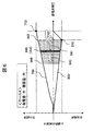
- FIG. 2 is a diagram showing the relationship between the chargeable / dischargeable power of the lead storage battery and the storage battery voltage.
- the chargeable / dischargeable power has a unique property that it depends on the storage battery voltage.
- the dischargeable power 700 is small when the storage battery voltage is low, increases as the storage battery voltage increases, reaches a maximum value at the position 710, and does not change even if the storage battery voltage increases further.
- the rechargeable power 800 is small when the storage battery voltage is low, increases as the storage battery voltage increases, reaches a maximum value at a position indicated by reference numeral 810, and rapidly decreases as the storage battery voltage increases further.
- the maximum dischargeable power position 710 and the maximum chargeable power position 810 do not match, and the maximum chargeable power position 810 is slightly lower than the maximum dischargeable power position 710.
- the chargeable / dischargeable power of the lead storage battery 320 depends on the storage battery voltage, so the performance of the lead storage battery 320 is maximized by setting and using the storage battery voltage so that the chargeable / dischargeable power is maximized. it can.
- the optimum voltage value between charging and discharging.
- priority is given to the characteristics of the chargeable power 800 having a steeper change gradient, and the storage battery voltage that gives the maximum point 810 is set as the optimum voltage Vopt.
- the other dischargeable electric power 700 is not a maximum value but is a relatively high value. Therefore, it can be said that the optimum voltage Vopt satisfies both the charging and discharging conditions.
- the lead storage battery 320 charges surplus power out of the power generated by the distributed power source 310 or supplies (discharges) power used by load devices (DC charger 400, AC charger 420, equipment load 500). It is necessary to do. Therefore, the storage battery voltage is not fixed to a constant value, but varies within a certain range. In this case, it is preferable in terms of efficiency that the operating range 900 is set before the optimum voltage Vopt of the lead storage battery 320. This is because when the optimum voltage Vopt (maximum point 810) is exceeded, the chargeable power 800 rapidly decreases. In addition, the voltage range of the operating range 900 varies depending on the charge / discharge amount of the lead storage battery 320.
- the voltage operating range 900 of the lead storage battery 320 is set as close as possible to the optimum voltage Vopt. Therefore, in the EMS 100, the storage battery target voltage calculation unit 140 calculates the operation target voltage Vt of the lead storage battery 320 based on the generated power predicted value from the generated power prediction unit 120 and the demand power predicted value from the demand power prediction unit 130. To PCS300. The PCS 300 sets a target voltage Vt for the lead storage battery 320 and performs charge / discharge control of the lead storage battery 320. The target voltage Vt is set as follows according to the generated power predicted value and the demand power predicted value.
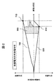
- FIG. 3 is a diagram showing a target voltage Vt1 set for the lead storage battery in case 1.
- the target voltage Vt1 in case 1 is set in the vicinity of the optimum voltage Vopt, as indicated by reference numeral 910. In this case, since both the predicted power generation value and the predicted power demand value are small, the fluctuation of the storage battery voltage is small, and the operating point can be kept near the optimum voltage Vopt.
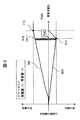
- FIG. 4 is a diagram showing a target voltage Vt2 set for the lead storage battery in case 2.
- the target voltage Vt2 in case 2 is set at a position lower than the optimum voltage Vopt, as indicated by reference numeral 920.
- the generated power prediction value is large, and surplus power of the power generated by the distributed power source 310 can be charged.
- the lead storage battery 320 is charged over time, and the storage battery voltage changes in the direction of the arrow 921, but is controlled so as not to exceed the optimum voltage Vopt indicated by reference numeral 922.
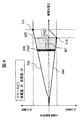
- FIG. 5 is a diagram showing the target voltage Vt3 set for the lead storage battery in Case 3.
- FIG. The target voltage Vt3 in case 3 is set in the vicinity of the optimum voltage Vopt as indicated by reference numeral 930. This is because the predicted power demand is large, and discharge from the lead storage battery 320 to the load device is possible. Thereafter, the lead storage battery 320 is discharged over time, and the storage battery voltage changes in the direction of the arrow 931, for example, to a position indicated by reference numeral 932.
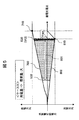
- FIG. 6 is a diagram showing a target voltage Vt4 set for the lead storage battery in case 4.
- the target voltage Vt4 in case 4 is set at a position lower than the optimum voltage Vopt, as indicated by reference numeral 940.
- both the predicted generated power value and the predicted power demand value are large, and both the charging operation and the discharging operation of the lead storage battery 320 are enabled.
- control is performed so as to change in the direction of arrow 941 and not exceed the optimum voltage Vopt indicated by reference numeral 942.
- the direction changes in the direction of the arrow 943 and drops to the position indicated by the reference numeral 944, for example.
- the target voltage Vt is set lower than the optimum voltage Vopt, but how much lower the target voltage Vt is set is determined by the storage battery target voltage calculation unit 140. That is, the target voltage Vt is determined by predicting the difference amount (surplus power) between the generated power predicted value and the demand power predicted value. Further, it goes without saying that whether or not the predicted charging power or discharging power can be handled by the current storage battery voltage of the lead storage battery 320 is taken into consideration.
- the lead storage battery 320 operates in a range near the optimum voltage Vopt, so that the chargeable / dischargeable power of the lead storage battery 320 can be increased, and a power supply system with high power efficiency is realized. Moreover, since the operating point of the lead storage battery 320 is set by predicting the generated power and the demand power, stable control can be performed even if the supply-demand balance fluctuates.
- various inventions can be formed by appropriately combining a plurality of components. That is, even if some constituent elements are deleted from all the constituent elements shown in the embodiment or a plurality of constituent elements are combined, it is within the scope of the present invention.
- EMS Energy management system
- 110 input unit
- 120 Generated power prediction unit
- 130 Power demand prediction unit
- 140 Storage battery target voltage calculation unit
- 150 output unit
- 200 connection point
- 310 distributed power supply
- 320 lead acid battery
- 400 DC charger
- 410 DC discharger
- 420 AC charger
- 430 AC discharger
- 500 equipment load
- 600 electric car
- 700 Dischargeable power
- 710 Maximum dischargeable power position
- 800 rechargeable power
- 810 Maximum chargeable power position
- 910 Target voltage Vt1 (case 1)
- 920 Target voltage Vt2 (Case 2)
- 930 target voltage Vt3 (case 3)
- 940 target voltage Vt4 (case 4), Vopt: optimal voltage.
Landscapes
- Engineering & Computer Science (AREA)
- Power Engineering (AREA)
- Supply And Distribution Of Alternating Current (AREA)
- Charge And Discharge Circuits For Batteries Or The Like (AREA)
Abstract
L'invention concerne un système d'alimentation électrique dans lequel un accumulateur au plomb est utilisé, une régulation stable et hautement efficace étant réalisée en considération des propriétés de l'accumulateur au plomb et de l'équilibre offre-demande. Un accumulateur au plomb (320) accumule la puissance générée par une source d'énergie (310) distribuée et la puissance reçue d'un système de puissance. Un système de gestion d'énergie (EMS) (100) prévoit la quantité de puissance générée par la source d'énergie (310) distribuée et la quantité de puissance demandée par des dispositifs de charge (400-600), et calcule en conséquence une valeur cible pour la tension de fonctionnement de l'accumulateur au plomb (320). Un système de conditionnement de puissance (PCS) (300) régule l'entrée/sortie de puissance par rapport à l'alimentation électrique (310) distribuée et à l'accumulateur au plomb (320) de sorte que la tension de fonctionnement de l'accumulateur au plomb (320) atteigne la valeur cible calculée par l'EMS (100).
Priority Applications (2)
| Application Number | Priority Date | Filing Date | Title |
|---|---|---|---|
| JP2015527728A JP5994027B2 (ja) | 2014-01-22 | 2014-01-22 | 電力供給システム及びこれに用いるエネルギーマネジメントシステム |
| PCT/JP2014/051180 WO2015111144A1 (fr) | 2014-01-22 | 2014-01-22 | Système d'alimentation électrique et système de gestion d'énergie utilisé dans ce dernier |
Applications Claiming Priority (1)
| Application Number | Priority Date | Filing Date | Title |
|---|---|---|---|
| PCT/JP2014/051180 WO2015111144A1 (fr) | 2014-01-22 | 2014-01-22 | Système d'alimentation électrique et système de gestion d'énergie utilisé dans ce dernier |
Publications (1)
| Publication Number | Publication Date |
|---|---|
| WO2015111144A1 true WO2015111144A1 (fr) | 2015-07-30 |
Family
ID=53680976
Family Applications (1)
| Application Number | Title | Priority Date | Filing Date |
|---|---|---|---|
| PCT/JP2014/051180 Ceased WO2015111144A1 (fr) | 2014-01-22 | 2014-01-22 | Système d'alimentation électrique et système de gestion d'énergie utilisé dans ce dernier |
Country Status (2)
| Country | Link |
|---|---|
| JP (1) | JP5994027B2 (fr) |
| WO (1) | WO2015111144A1 (fr) |
Cited By (6)
| Publication number | Priority date | Publication date | Assignee | Title |
|---|---|---|---|---|
| CN105244900A (zh) * | 2015-11-20 | 2016-01-13 | 许继集团有限公司 | 一种基于移频控制的微电网离网能量平衡控制方法 |
| CN105576710A (zh) * | 2016-02-18 | 2016-05-11 | 东南大学 | 一种综合能源系统中的分布式电源的配置方法 |
| CN106229992A (zh) * | 2016-08-29 | 2016-12-14 | 西电通用电气自动化有限公司 | 电力市场下的微电网能量管理方法 |
| CN110380441A (zh) * | 2019-07-19 | 2019-10-25 | 国电南瑞科技股份有限公司 | 识别特高压直流闭锁、再启动状态的稳控判据方法和装置 |
| WO2020155303A1 (fr) * | 2019-02-01 | 2020-08-06 | 国网江苏省电力有限公司 | Procédé, terminal, système et support pour interaction de charge de réseau de stockage d'énergie de batterie |
| CN115208023A (zh) * | 2022-07-29 | 2022-10-18 | 三一汽车制造有限公司 | 取电控制方法、装置、设备、介质、产品及作业机械 |
Citations (3)
| Publication number | Priority date | Publication date | Assignee | Title |
|---|---|---|---|---|
| JP2012165501A (ja) * | 2011-01-17 | 2012-08-30 | Jc Service Co Ltd | 複数拠点接続型省電力制御システム |
| JP2013165534A (ja) * | 2010-06-03 | 2013-08-22 | Sanyo Electric Co Ltd | 給電制御装置 |
| JP2013176234A (ja) * | 2012-02-27 | 2013-09-05 | Hitachi Ltd | 独立型電力供給システム |
Family Cites Families (1)
| Publication number | Priority date | Publication date | Assignee | Title |
|---|---|---|---|---|
| JP5639540B2 (ja) * | 2011-06-29 | 2014-12-10 | 株式会社日立製作所 | 蓄電池需給計画作成装置および蓄電池需給計画作成方法 |
-
2014
- 2014-01-22 JP JP2015527728A patent/JP5994027B2/ja not_active Expired - Fee Related
- 2014-01-22 WO PCT/JP2014/051180 patent/WO2015111144A1/fr not_active Ceased
Patent Citations (3)
| Publication number | Priority date | Publication date | Assignee | Title |
|---|---|---|---|---|
| JP2013165534A (ja) * | 2010-06-03 | 2013-08-22 | Sanyo Electric Co Ltd | 給電制御装置 |
| JP2012165501A (ja) * | 2011-01-17 | 2012-08-30 | Jc Service Co Ltd | 複数拠点接続型省電力制御システム |
| JP2013176234A (ja) * | 2012-02-27 | 2013-09-05 | Hitachi Ltd | 独立型電力供給システム |
Cited By (8)
| Publication number | Priority date | Publication date | Assignee | Title |
|---|---|---|---|---|
| CN105244900A (zh) * | 2015-11-20 | 2016-01-13 | 许继集团有限公司 | 一种基于移频控制的微电网离网能量平衡控制方法 |
| CN105576710A (zh) * | 2016-02-18 | 2016-05-11 | 东南大学 | 一种综合能源系统中的分布式电源的配置方法 |
| CN106229992A (zh) * | 2016-08-29 | 2016-12-14 | 西电通用电气自动化有限公司 | 电力市场下的微电网能量管理方法 |
| WO2020155303A1 (fr) * | 2019-02-01 | 2020-08-06 | 国网江苏省电力有限公司 | Procédé, terminal, système et support pour interaction de charge de réseau de stockage d'énergie de batterie |
| US11081885B2 (en) | 2019-02-01 | 2021-08-03 | State Grid Jiangsu Electric Power Co., Ltd. | Battery energy storage grid-load interactive method, terminal, system and medium for superimposed control |
| CN110380441A (zh) * | 2019-07-19 | 2019-10-25 | 国电南瑞科技股份有限公司 | 识别特高压直流闭锁、再启动状态的稳控判据方法和装置 |
| CN110380441B (zh) * | 2019-07-19 | 2021-01-22 | 国电南瑞科技股份有限公司 | 识别特高压直流闭锁、再启动状态的稳控判据方法和装置 |
| CN115208023A (zh) * | 2022-07-29 | 2022-10-18 | 三一汽车制造有限公司 | 取电控制方法、装置、设备、介质、产品及作业机械 |
Also Published As
| Publication number | Publication date |
|---|---|
| JP5994027B2 (ja) | 2016-09-21 |
| JPWO2015111144A1 (ja) | 2017-03-23 |
Similar Documents
| Publication | Publication Date | Title |
|---|---|---|
| JP6304008B2 (ja) | 電力供給システム | |
| JP5327407B2 (ja) | 蓄電池システム及びその制御方法 | |
| KR102400502B1 (ko) | 에너지 저장 시스템 | |
| US10084314B2 (en) | Storage battery equipment | |
| JP5738212B2 (ja) | 電力貯蔵型の発電システム | |
| JP5011230B2 (ja) | 二次電池の制御装置および制御方法 | |
| JP5994027B2 (ja) | 電力供給システム及びこれに用いるエネルギーマネジメントシステム | |
| EP2587623A1 (fr) | Système de distribution électrique à courant continu | |
| US20130187466A1 (en) | Power management system | |
| WO2015041253A1 (fr) | Installation de charge et procédé de gestion d'énergie pour installation de charge | |
| JPWO2010125878A1 (ja) | 制御装置および制御方法 | |
| JP2013176282A (ja) | 発電設備及び電力貯蔵装置を備えた発電システム及びその制御方法並びにプログラム | |
| JP2014131369A (ja) | 電力制御システム | |
| US9608449B2 (en) | Power system and control method of the power system | |
| JP2014236600A (ja) | 系統用蓄電池の複数目的制御装置 | |
| WO2011152512A1 (fr) | Dispositif de commande d'alimentation électrique | |
| KR101215396B1 (ko) | 방전전류제어를 이용한 하이브리드 스마트그리드 무정전전원장치 | |
| KR102053812B1 (ko) | 하이브리드 배터리에 연결된 전력 변환 시스템을 제어하기 위한 방법 및 시스템 | |
| JP6865651B2 (ja) | 分散型電源システム | |
| JP7331562B2 (ja) | 電力需給制御システム、電力需給制御装置、及び電力需給制御方法 | |
| JP6055968B2 (ja) | 電源システム | |
| JP6390259B2 (ja) | 充放電制御装置及び充放電制御方法 | |
| JP6351200B2 (ja) | 電力供給システム | |
| JP2019030162A (ja) | 分散型電源システム | |
| JP2013031349A (ja) | 蓄電池システム |
Legal Events
| Date | Code | Title | Description |
|---|---|---|---|
| ENP | Entry into the national phase |
Ref document number: 2015527728 Country of ref document: JP Kind code of ref document: A |
|
| 121 | Ep: the epo has been informed by wipo that ep was designated in this application |
Ref document number: 14879303 Country of ref document: EP Kind code of ref document: A1 |
|
| NENP | Non-entry into the national phase |
Ref country code: DE |
|
| 122 | Ep: pct application non-entry in european phase |
Ref document number: 14879303 Country of ref document: EP Kind code of ref document: A1 |