WO2015111165A1 - 乾燥速度測定装置および乾燥速度測定方法 - Google Patents
乾燥速度測定装置および乾燥速度測定方法 Download PDFInfo
- Publication number
- WO2015111165A1 WO2015111165A1 PCT/JP2014/051337 JP2014051337W WO2015111165A1 WO 2015111165 A1 WO2015111165 A1 WO 2015111165A1 JP 2014051337 W JP2014051337 W JP 2014051337W WO 2015111165 A1 WO2015111165 A1 WO 2015111165A1
- Authority
- WO
- WIPO (PCT)
- Prior art keywords
- humidity
- temperature
- test piece
- mass
- measured
- Prior art date
- Legal status (The legal status is an assumption and is not a legal conclusion. Google has not performed a legal analysis and makes no representation as to the accuracy of the status listed.)
- Ceased
Links
Images


Classifications
-
- G—PHYSICS
- G01—MEASURING; TESTING
- G01N—INVESTIGATING OR ANALYSING MATERIALS BY DETERMINING THEIR CHEMICAL OR PHYSICAL PROPERTIES
- G01N5/00—Analysing materials by weighing, e.g. weighing small particles separated from a gas or liquid
- G01N5/02—Analysing materials by weighing, e.g. weighing small particles separated from a gas or liquid by absorbing or adsorbing components of a material and determining change of weight of the adsorbent, e.g. determining moisture content
- G01N5/025—Analysing materials by weighing, e.g. weighing small particles separated from a gas or liquid by absorbing or adsorbing components of a material and determining change of weight of the adsorbent, e.g. determining moisture content for determining moisture content
-
- G—PHYSICS
- G01—MEASURING; TESTING
- G01N—INVESTIGATING OR ANALYSING MATERIALS BY DETERMINING THEIR CHEMICAL OR PHYSICAL PROPERTIES
- G01N5/00—Analysing materials by weighing, e.g. weighing small particles separated from a gas or liquid
- G01N5/04—Analysing materials by weighing, e.g. weighing small particles separated from a gas or liquid by removing a component, e.g. by evaporation, and weighing the remainder
-
- G—PHYSICS
- G01—MEASURING; TESTING
- G01N—INVESTIGATING OR ANALYSING MATERIALS BY DETERMINING THEIR CHEMICAL OR PHYSICAL PROPERTIES
- G01N25/00—Investigating or analyzing materials by the use of thermal means
- G01N25/56—Investigating or analyzing materials by the use of thermal means by investigating moisture content
-
- G—PHYSICS
- G01—MEASURING; TESTING
- G01N—INVESTIGATING OR ANALYSING MATERIALS BY DETERMINING THEIR CHEMICAL OR PHYSICAL PROPERTIES
- G01N9/00—Investigating density or specific gravity of materials; Analysing materials by determining density or specific gravity
- G01N9/36—Analysing materials by measuring the density or specific gravity, e.g. determining quantity of moisture
Definitions
- the present invention relates to a drying speed measuring device and a drying speed measuring method used for evaluating the water-absorbing quick-drying property of fabrics such as textile products.
- the JISL1096 drying test method can be cited as a standardized drying test (drying rate evaluation) method.
- a 40 cm ⁇ 40 cm test piece is taken from a sample prepared by a conventional method, spread and immersed in water at 20 ° C. ⁇ 2 ° C., sufficiently absorbed, and then pulled up from the water. .
- attach a test piece to the hanging clip of the drying time measuring device equipped with a strain gauge measure the time until it naturally dry in the standard test chamber, and use the average value to determine the drying speed. calculate.
- Patent Document 1 discloses a specific automatic drying property measuring apparatus.
- the automatic drying property measuring apparatus is composed of a test piece mounting hanger for attaching a test piece dough, a hanger holder, a mass measuring means, a movable base, a hanger holder driving means, a driving means, and a computing means.
- the hanger holder holds the test piece mounting hanger horizontally.
- the mass measuring means measures the mass of the test piece mounting hanger.
- the movable base holds the hanger holder vertically and is movable in the horizontal direction with respect to the fixed base.
- the hanger holder driving means moves the hanger holder up and down, and the driving means moves the movable base.
- the calculating means includes time measuring means for calculating the time from the driving means being driven based on the start of the measurement signal to the subsequent measurement start.
- JIS Z 8703 standard conditions relating to temperature, humidity, and atmospheric pressure at the place where tests are conducted in the mining industry.
- JIS Z 8703 standard conditions relating to temperature, humidity, and atmospheric pressure at the place where tests are conducted in the mining industry.
- JIS Z 8703 standard conditions relating to temperature, humidity, and atmospheric pressure at the place where tests are conducted in the mining industry.
- JIS L 0105 general rules for physical testing of textile products, a temperature of 20 ⁇ 2 ° C. and a humidity of 65 ⁇ 4% are defined as standard conditions.
- the dryness test described above is performed within the tolerance range of the standard state.
- Patent Document 1 specifically describes the results of a test performed with an automatic drying property measurement apparatus in a measurement chamber of a standard state of 20 ° C. and 65% RH.
- the present invention has been made in view of the above-described circumstances, and an object thereof is to improve the accuracy of measurement of the drying speed of a fabric such as a textile product even within a tolerance range of a standard state.
- a drying rate measuring apparatus comprises: A water application section for attaching water to the test piece of the fabric, A holding part for holding the test piece in a spread state, In a state where the test piece to which water has been attached is held by the holding unit, the mass of the test piece is continuously measured, and a mass measuring unit that stores the measured mass in association with the elapsed time; While the mass measuring unit measures the mass of the test piece, the temperature and humidity at a certain position are continuously measured with respect to the test piece, and the measured temperature and humidity are stored in correspondence with the elapsed time.
- the drying rate measuring method comprises: A water application step for attaching water to the test piece of the fabric, With the test piece spread out and held stationary, the mass of the test piece and the temperature and humidity at a certain position with respect to the test piece are continuously measured, and the measured mass, temperature, and humidity and progress are measured.
- the temperature and humidity at a certain position with respect to the test piece are continuously measured, and the change in the mass of the measured test piece is normalized from the measured temperature and humidity to the predetermined temperature and humidity conditions. Therefore, the accuracy of measuring the drying speed of the dough can be improved even within the tolerance range of the standard state.
- FIG. 4 is a flowchart showing an example of an operation of drying speed measurement according to the first embodiment. 4 is a flowchart showing an example of an operation for normalizing a temperature and humidity condition according to the first embodiment. It is a figure which shows the structure of the drying rate measuring apparatus which concerns on Embodiment 2 of this invention. It is a figure which shows the structure of the moisture provision part which concerns on Embodiment 2. FIG. It is a figure which shows the drying rate measurement result which concerns on the Example of this invention.
- the fabric is defined to include a knitted material and a non-woven fabric in addition to the cloth / woven fabric.
- FIG. 1 is a block diagram showing a configuration example of a drying rate measuring apparatus according to Embodiment 1 of the present invention.
- the drying speed measuring device 10 includes a water applying unit 1, a holding unit 2, a mass measuring unit 3, a temperature / humidity measuring unit 4, and a control unit 5.
- the control unit 5 includes a storage unit 6, a temperature / humidity normalization unit 8, and a timer unit 7.
- the drying speed measuring device 10 causes water to adhere to the fabric specimen 20 and measures the speed at which the attached water dries.
- the adhering water soaks into the test piece 20 and is held in the gap between the fibers, so that there is a difference in the drying speed depending on the material of the test piece 20.
- the test piece 20 Prior to measurement of the drying rate, the test piece 20 is placed in a standard state for measuring the drying rate for a while, and the humidity is adjusted so that the temperature and moisture of the test piece 20 do not change in the standard state.
- the mass of the test piece 20 is measured before water is attached to the test piece 20.
- the mass of the test piece 20 can be measured by the mass measuring unit 3 while being held by the holding unit 2.
- the mass measuring unit 3 measures the total mass of the holding unit 2 and the test piece 20. If the mass of the holding part 2 is measured in advance, the mass of the test piece 20 can be determined from the difference therebetween.
- a certain amount of water is attached to the test piece 20 at a predetermined position of the test piece 20, for example, the center.
- a certain amount of water is measured with a pipette (mespipet, micropipette) and dropped onto the test piece 20. You may make it drop to the test piece 20 with a syringe pump or an infusion pump. Alternatively, a predetermined amount of water may be dropped into a container that can be accommodated flatly by spreading the test piece 20, and the test piece 20 may be placed on the test piece 20 to allow water to adhere thereto.
- the holding unit 2 holds the test piece 20 in a state where the test piece 20 is expanded. For example, the holding unit 2 suspends the test piece 20 across at least a part of one side of the test piece 20.
- a structure in which the container is held may be used.
- the drying speed varies depending on the strength of the wind hitting the test piece 20, so it is desirable to keep the wind hitting the test piece 20 constant.
- the test piece 20 is suspended, the test piece 20 is shaken when the wind hits, and the mass cannot be measured accurately. If possible, it is desirable to cover the test piece 20 with a windshield so that the wind does not hit it.
- the mass measuring unit 3 is composed of, for example, a precision balance, and continuously measures the mass of the test piece 20 with the test piece 20 held by the holding unit 2. As described above, the mass measuring unit 3 measures the total mass of the holding unit 2 and the test piece 20, but since the mass of the holding unit 2 is constant, the mass of the test piece 20 is to be measured. . The mass measuring unit 3 sends the measured mass to the control unit 5. The control unit 5 stores the received mass in the storage unit 6 in association with the elapsed time when the mass is measured (when the mass is received).
- the elapsed time is measured by the timer 7.
- the timer 7 has a built-in clock, for example, and outputs time data when referenced.
- the elapsed time is a value obtained by subtracting the time when the mass of the test piece 20 to which water is attached is first measured from the time when the mass is measured.
- the timekeeping unit 7 may be reset when measurement is started, and an elapsed time with the measurement start as the origin (0) may be output.
- the temperature / humidity measuring unit 4 is supported at a fixed position with respect to the test piece 20 and continuously measures the temperature and relative humidity at the fixed position with respect to the test piece 20.
- humidity refers to relative humidity.
- the position where the temperature and humidity are measured is preferably near the portion where water is attached within the range where the test piece 20 is not contacted.
- the temperature / humidity measuring unit 4 is installed inside the windshield, and the temperature and humidity are measured inside the windshield.
- the temperature / humidity measuring unit 4 measures the temperature and humidity of the air around the test piece 20.
- the temperature / humidity measurement unit 4 sends the measured temperature and humidity to the control unit 5.
- the control unit 5 stores the received temperature and humidity in the storage unit 6 in association with the elapsed time when they are measured (when the temperature and humidity are received).
- a method of obtaining a relative humidity by a wet air diagram or calculation from a dry bulb temperature and a wet bulb temperature measured by a moisture meter can be used.
- the relative humidity may be measured with a hygrometer.
- the humidity measured with an electric hygrometer is normalized with the measured temperature to obtain a measured value.
- FIG. 2 is a diagram illustrating an example of a data structure of measurement data according to the first embodiment.
- the mass, temperature, and humidity are measured for each elapsed time of a fixed period, and the mass mi, temperature Ti, and humidity Hi are stored corresponding to the elapsed time ti.
- the elapsed time when measurement is started is t0, mass m0, temperature T0, and humidity H0.
- the temperature / humidity normalization unit 8 in FIG. 1 performs a predetermined change in the measured mass from the elapsed time, mass, temperature, and humidity stored in the storage unit 6 after a specified time has elapsed since the start of measurement. Normalize by converting to temperature and humidity conditions. When the normalization is instructed, the temperature / humidity normalizing unit 8 may convert the change in the mass measured so far into the predetermined temperature and humidity conditions.
- FIG. 3 is a diagram illustrating a concept of normalization to a predetermined temperature and humidity condition according to the first embodiment.
- the horizontal axis is the elapsed time, and the vertical axis is the mass of the test piece 20.
- the measured mass of the test piece 20 is represented by a solid actual measurement mass.
- FIG. 3 shows a case where the measured temperature is higher than a predetermined temperature (standard temperature) which is a condition for conversion, or is lower than a predetermined humidity (standard humidity) which is a condition for conversion. In that case, normally, moisture evaporates faster than the standard temperature and standard humidity conditions (standard temperature and humidity conditions), so the measured mass becomes smaller than the mass under the standard temperature and humidity conditions as time passes.
- standard temperature standard temperature
- standard humidity standard humidity
- the mass (change) of the standard temperature and humidity conditions can be calculated by converting the measured drying rate at the temperature and humidity into the drying rate at the standard temperature and humidity.
- the water vapor partial pressure difference at the measured temperature and humidity and the water vapor partial pressure difference at the standard temperature and humidity are used.
- the water vapor partial pressure difference at standard temperature and humidity is known in advance.
- the difference between the mass of the test piece 20 that is being measured by attaching moisture and the mass of the test piece 20 before the moisture is attached is the residual moisture.
- the ratio of the residual moisture and the adhered moisture is the residual moisture content.
- the residual moisture content at the standard elapsed time (point N in FIG. 3) of the normalized mass ( mass under standard temperature and humidity conditions: the two-dot chain line in FIG. 3) obtained by converting the actually measured mass into the standard temperature and humidity.
- a drying rate of 20 can be evaluated. In the reference elapsed time, the larger the residual moisture content, the slower the drying speed, and the smaller the residual moisture content, the faster the drying speed.
- the change in mass is converted into the standard temperature and humidity conditions, but it can also be considered that the reference elapsed time changes depending on the temperature and humidity. That is, at the measured temperature and humidity, it is considered that the reference elapsed time is shorter if the water evaporation is faster than the standard temperature and humidity condition, and the reference elapsed time is longer if the water evaporation is slower than the standard temperature and humidity condition.
- the normalization coefficient of the elapsed time in this case can also be calculated using the water vapor partial pressure difference. For example, an elapsed time (actual elapsed time) in which the elapsed time (normalized time) normalized by the normalization coefficient becomes the reference elapsed time is calculated. Then, the actually measured mass at the actual elapsed time is regarded as the mass of the standard temperature and humidity condition at the reference elapsed time, and the residual moisture content is calculated. This will be described in detail below.
- the liquid phase water vapor partial pressure can be determined from the wet bulb temperature.
- the liquid phase water vapor partial pressure can be calculated by obtaining the wet bulb temperature from the temperature and relative humidity using a wet air diagram.
- the standard wet bulb temperature Twstd 15.83633 ° C., which is the wet bulb temperature at that time.
- the water vapor partial pressure difference ⁇ Pw_std of the standard condition is 2.794476319.
- W_i be the mass of the test piece 20 at the elapsed time ti.
- the average dry bulb temperature Td_i, wet bulb temperature Tw_i, and relative humidity RH_i between the elapsed times ti and ti-1 are used.
- the water vapor partial pressure difference at that time is represented by ⁇ Pw_i.
- the mass of the test piece changes by ⁇ W′_i during ⁇ ti, and if it is plotted, a mass curve under standard temperature and humidity conditions can be obtained. If the mass of the standard elapsed time is calculated from the mass curve under the standard temperature and humidity conditions, for example, by interpolation, the residual moisture content of the standard elapsed time can be obtained.
- the elapsed time difference ⁇ t_i when measured at the standard temperature and humidity becomes 1 / K_i times from the formula of the water decrease amount ⁇ W′_i during ⁇ ti in the standard state.
- the control unit 5 is composed of, for example, a computer.
- the computer of the control unit 5 includes an arithmetic device (CPU), a storage device, an input / output device, and a display device.
- the control program loaded in the storage device is executed by the arithmetic device and performs the above-described processing.
- the mass measuring unit 3 and the temperature / humidity measuring unit 4 are connected to an input / output device.
- the timer unit 7 is configured by a clock or a clock counter provided in the computer.
- a storage unit configured in the storage device according to the elapsed time read from the time measuring unit 7 by inputting mass, temperature, and humidity data from the mass measuring unit 3 and the temperature / humidity measuring unit 4 according to the command of the control program 6 is stored.
- storage part 6 is comprised by the memory
- the control program performs normalization by referring to the elapsed time, mass, temperature, and humidity data from the storage unit 6 configured in the storage device, and calculates the residual moisture content. Then, for example, the residual moisture content is displayed on the display device.
- FIG. 4 is a flowchart showing an example of the drying speed measurement operation according to the first embodiment.
- the test piece 20 Prior to the drying rate measurement, the test piece 20 is placed in a standard state where the drying rate is measured for a while so that the temperature and moisture of the test piece 20 do not change in the standard state. And the mass of the test piece 20 is measured in the state which does not make water adhere.
- a predetermined amount of water is attached to the test piece 20 at a predetermined position by the water applying unit 1 (step S01).
- the test piece 20 to which water is attached is held by the holding unit 2 (step S02).
- the mass measurement unit 3 measures the mass of the test piece 20, and the temperature / humidity measurement unit 4 measures the temperature and humidity (or wet bulb temperature) at a certain position from the test piece 20, and stores them in the storage unit 6 corresponding to the elapsed time. (Step S03). While the specified time has not elapsed (step S04; NO), the mass, temperature and humidity are continuously measured and stored in the storage unit 6 (step S03).
- step S04 When the specified time has elapsed (step S04; YES), the change in mass is normalized from the temperature and humidity (or wet bulb temperature) stored in the storage unit 6 to the standard temperature and humidity conditions (step). S05).
- FIG. 5 is a flowchart showing an example of the temperature and humidity condition normalization operation according to the first embodiment.
- the operation of FIG. 5 is a decomposition of the temperature and humidity condition normalization (step S05) of FIG.
- step S05 the water vapor partial pressure difference at the measured temperature and humidity is calculated
- step S12 a normalization coefficient that is a ratio of the measured water vapor partial pressure difference at the temperature and humidity to the water vapor partial pressure difference at the standard temperature and humidity is calculated (step S12).
- the actual elapsed time is calculated in which the normalized time obtained by dividing the elapsed time by the normalization coefficient (accumulation thereof) becomes the reference elapsed time (step S13). Then, the residual moisture content is calculated from the mass of the test piece 20 corresponding to the actual elapsed time (step S14). This residual moisture content is output as the residual moisture content of the reference elapsed time in the standard state of the test piece 20.
- the temperature and humidity at a certain position are continuously measured with respect to the test piece 20 on which water is adhered at a predetermined position, Since the change in the mass of the measured specimen 20 is normalized from the measured temperature and humidity to the predetermined temperature and humidity conditions, the accuracy of measuring the drying speed of the dough is improved even within the tolerance range of the standard state. Can do.
- the test piece 20 held by the holding unit 2 is separated in a state where the wind does not directly hit the test piece 20 and the air diffuses between the external space and the internal space.
- the water provision part 1 dripping a fixed quantity of water at the fixed speed
- FIG. 6 is a diagram showing the configuration of the drying rate measuring apparatus according to the second embodiment of the present invention.
- the water provision part 1 is abbreviate
- the drying speed measuring apparatus 10 includes a windshield 9.
- FIG. 6 shows a cross section of the windshield 9.
- an opening 11 is formed through the space outside the windshield 9 and the internal space, and a mesh sheet 12 is disposed so as to cover the opening 11.
- the mesh sheet 12 allows air to pass between the meshes, and the air diffuses between the space outside the windshield 9 and the space inside.
- the mesh sheet 12 is resistant to wind, the wind in the windshield 9 can be ignored when the windshield 9 is placed in a room where the movement of the air mass is small.
- the holding part 2 suspends the test piece 20 across a part of one side of the test piece 20.
- the test piece 20 is held vertically in an expanded state.
- the holding unit 2 and the test piece 20 are accommodated in the windshield 9 and covered with the windshield 9.
- the holding part 2 and the test piece 20 are supported separately from the windshield 9.
- the mass measuring unit 3 is composed of a precision balance and is disposed on the windshield 9.
- the holding unit 2 is suspended from the precision balance of the mass measuring unit 3 through a hole formed in the upper surface of the windshield 9.
- the mass measuring unit 3 measures the total mass of the holding unit 2 and the test piece 20.
- the temperature / humidity measuring unit 4 is installed inside the windshield 9.
- the temperature / humidity measuring unit 4 measures the temperature and humidity at a certain position near the portion of the test piece 20 to which water is attached. In FIG. 6, it is assumed that water adheres to the center of the test piece 20.
- FIG. 7 is a diagram illustrating a configuration of the moisture applying unit according to the second embodiment.
- the water applying unit 1 includes a container 13 for storing water, an infusion pump 14, a nozzle 15, and a holding table 16.
- the nozzle 15 is supported at a fixed position with respect to the test piece 20 held on the holding table 16.
- the infusion pump 14 draws out water from the container 13 and drops a constant amount of water from the nozzle 15 at a constant speed.
- the holding table 16 does not contact the test piece 20 at a portion where water is dropped. Therefore, the conditions for attaching water to the test piece 20 are kept constant.
- the control unit 5 in FIG. 6 is the same as the control unit 5 in the first embodiment.
- the storage unit 6 stores the measured mass, temperature and humidity in association with the elapsed time.
- the temperature / humidity normalizing unit 8 normalizes the measured change in mass from the elapsed time, mass, temperature, and humidity stored in the storage unit 6 by converting the change into a predetermined temperature and humidity condition. .
- the drying rate measuring apparatus 10 Since the drying rate measuring apparatus 10 according to the second embodiment is configured as described above, the temperature and humidity of the air in contact with the portion where the water evaporated from the test piece 20 immediately diffuses and the water evaporates are The test piece 20 can be placed in a state where it is not different from the temperature and humidity of the surrounding air. Further, it is possible to prevent the wind from hitting the test piece 20. Furthermore, since the conditions for adhering water to the test piece 20 can be made constant, the drying rate can be evaluated including how the test piece 20 spreads water.
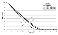
- the drying rate was measured in two different places using the drying rate measuring apparatus 10 of the above-mentioned Embodiment 2, and each result was compared before normalization and after normalization.
- a 20 cm ⁇ 20 cm test piece 20 was cut out from a 100% polyester knit fabric having a basis weight of 138 g / m 2 .
- a distance is kept between the tip of the nozzle 15 and the test piece 20 so that water does not drip, and purified water is 0 at the center of the test piece at a rate of 0.01 ml / sec. 3 ml was supplied.
- the test piece 20 to which water was attached was attached to the holding unit 2, accommodated together with the holding unit 2 in the windshield 9, and suspended from the mass measuring unit 3.
- an electronic balance MS3045S / 02 manufactured by METTLER TOLEDO Co., Ltd. was used for the mass measurement.
- the temperature and humidity near the portion of the test piece 20 to which water was applied was measured using a Rotronic temperature and humidity sensor HC2-S. And the measurement result was collected and recorded by the control part comprised from a computer.
- the initial moisture mass was W0
- the moisture weight t minutes after the start of measurement was Wt
- the residual moisture content ERt (Wt / W0) ⁇ 100 after t minutes was determined.
- Test environment A has an average temperature of 21.2 ° C. and an average relative humidity of 60.8%.
- Test environment B has an average temperature of 20.3 ° C. and an average relative humidity of 67%. These are the ranges of temperature 20 ⁇ 2 ° C. and humidity 65 ⁇ 4%, which are defined as standard conditions in the physical test method general rules of JIS L 0105 during the test.
- FIG. 8 is a diagram showing the measurement results of the drying speed according to the example of the present invention.
- the residual moisture content P before normalization of the test environment A and the residual moisture content Q before normalization of the test environment B differ by about 10% in 30 minutes from the start of the test and about 14% in 40 minutes.
- the residual moisture content R after normalization of the test environment A and the residual moisture content S after normalization of the test environment B are very close. It can be said that the residual moisture content after normalization is not significantly different in the error ranges of temperature and humidity and mass measurement.
Landscapes
- Physics & Mathematics (AREA)
- Health & Medical Sciences (AREA)
- Life Sciences & Earth Sciences (AREA)
- Chemical & Material Sciences (AREA)
- Analytical Chemistry (AREA)
- Biochemistry (AREA)
- General Health & Medical Sciences (AREA)
- General Physics & Mathematics (AREA)
- Immunology (AREA)
- Pathology (AREA)
- Investigating Or Analyzing Materials Using Thermal Means (AREA)
- Treatment Of Fiber Materials (AREA)
- Drying Of Solid Materials (AREA)
Abstract
Description
生地の試験片に水を付着させる水付与部と、
前記試験片を広げた状態で静止させて保持する保持部と、
水が付着された前記試験片を前記保持部で保持した状態で、前記試験片の質量を継続的に測定し、測定した質量と経過時間を対応させて記憶する質量測定部と、
前記質量測定部で前記試験片の質量を測定する間、前記試験片に対して一定の位置の温度および湿度を継続的に測定し、測定した温度および湿度と経過時間を対応させて記憶する温湿度測定部と、
前記質量測定部で測定した質量の変化を、前記温湿度測定部で測定した温度および湿度から所定の温度および湿度の条件に換算する正規化部と、
を備えることを特徴とする。
生地の試験片に水を付着させる水付与ステップと、
前記試験片を広げて静止させて保持した状態で、前記試験片の質量と、前記試験片に対して一定の位置の温度および湿度を継続的に測定し、測定した質量、温度および湿度と経過時間を対応させて記憶する測定ステップと、
前記測定ステップで測定した質量の変化を、前記測定ステップで測定した温度および湿度から所定の温度および湿度の条件に換算する正規化ステップと、
を備えることを特徴とする。
図1は、本発明の実施の形態1に係る乾燥速度測定装置の構成例を示すブロック図である。乾燥速度測定装置10は、水付与部1、保持部2、質量測定部3、温湿度測定部4および制御部5から構成される。制御部5には、記憶部6、温湿度正規化部8および計時部7が含まれる。
e(T)=6.1078×10(7.5T/(T+237.3))
乾球温度:Td(℃)、湿球温度:Tw(℃)、相対湿度RH(%)として、液相水蒸気分圧をPww=e(Tw)、気相水蒸気分圧をPwa=e(Td)で表すと、水蒸気分圧差ΔPwは、
ΔPw=Pww-Pwa
である。
K_i=ΔPw_std/ΔPw_i
である。
R_i=ΔW_i/Δti
である。蒸発した水が速やかに拡散し、水が蒸発する部分の近傍の空気の温湿度と離れた場所の空気の温湿度の差を無視できるとすれば、乾燥速度は水蒸気分圧差に比例すると考えてよい。その条件では、測定した乾燥速度R_iを標準温湿度に換算した正規化後乾燥速度R’_iは、
R’_i=K_i・R_i
で表すことができる。
ΔW’_i=R’_i・Δti=K_i・R_i・Δti
である。標準状態ではΔtiの間に、試験片の質量はΔW’_iだけ変化するから、それをプロットしていけば、標準温湿度条件における質量の曲線が得られる。標準温湿度条件の質量の曲線から、例えば内挿法によって基準経過時間の質量を算出すれば、基準経過時間の残留水分率が分かる。
Mc=(W_n-Wf)/Ww
を算出し、その試験片20の標準温湿度条件における基準経過時間の残留水分率とすることができる。なお、正規化係数K_iが一定なら、基準経過時間に正規化係数を乗じた値を実経過時間とすることができる。
乾燥速度を正確に測定するには、蒸発した水分がただちに拡散して、水分が蒸発する部分に接する空気の温度および湿度が、周りの空気の温度および湿度と変わりがなく、熱および湿気のこもりがないという状態に、試験片20を置くことが必要である。また、前述のとおり風が試験片20に当たらないようにすることが必要である。さらに、試験片20に付着させる水の拡がり方も、試験片20の乾燥速度の性質に寄与しているので、それも含めて乾燥速度を評価する必要がある。
2 保持部
3 質量測定部
4 温湿度測定部
5 制御部
6 記憶部
7 計時部
8 温湿度正規化部
9 風防
10 乾燥速度測定装置
11 開口
12 網目状シート
13 容器
14 輸液ポンプ
15 ノズル
16 保持台
20 試験片
Claims (16)
- 生地の試験片に水を付着させる水付与部と、
前記試験片を広げた状態で静止させて保持する保持部と、
水が付着された前記試験片を前記保持部で保持した状態で、前記試験片の質量を継続的に測定し、測定した質量と経過時間を対応させて記憶する質量測定部と、
前記質量測定部で前記試験片の質量を測定する間、前記試験片に対して一定の位置の温度および湿度を継続的に測定し、測定した温度および湿度と経過時間を対応させて記憶する温湿度測定部と、
前記質量測定部で測定した質量の変化を、前記温湿度測定部で測定した温度および湿度から所定の温度および湿度の条件に換算する正規化部と、
を備える乾燥速度測定装置。 - 前記正規化部は、前記質量測定部で測定した質量の変化から、前記温湿度測定部で測定した温度および湿度における乾燥速度を算出し、前記温湿度測定部で測定した温度および湿度から水蒸気分圧差を算出して、前記所定の温度および湿度の条件に前記乾燥速度を換算し、前記所定の温度および湿度における所定の時間経過後の残留水分率を算出する、請求項1に記載の乾燥速度測定装置。
- 前記正規化部は、前記所定の温度および湿度における水蒸気分圧差と、前記温湿度測定部で測定した温度および湿度における水蒸気分圧差の比である正規化係数を算出し、計測した経過時間である実経過時間を前記正規化係数で除した正規化時間が、前記所定の経過時間になる前記実経過時間に対応する残留水分率を、前記所定の温度および湿度における所定の時間経過後の残留水分率として算出する、請求項2に記載の乾燥速度測定装置。
- 風が直接前記試験片に当たらず、かつ、外部の空間と内部の空間とで相互に空気が拡散する状態で、前記保持部に保持された試験片を離隔して覆う風防を備え、
前記質量測定部は、前記風防の内部に前記保持部で前記試験片を保持した状態で、前記試験片の質量を測定し、
前記温湿度測定部は、前記風防の内部に前記保持部で前記試験片を保持した状態で、前記風防内部の前記試験片に対して一定の位置の温度および湿度を継続的に測定する、
請求項1ないし3のいずれか1項に記載の乾燥速度測定装置。 - 前記風防は、風防の外部の空間と内部の空間とを通じる開口が形成され、該開口を覆う網目状シートを備える請求項4に記載の乾燥速度測定装置。
- 前記水付与部は、前記試験片の定めた位置に、一定量の水を定めた速度で滴下する、請求項1ないし5のいずれか1項に記載の乾燥速度測定装置。
- 前記水付与部は、輸液ポンプと、該輸液ポンプの先端に備えられ前記試験片から一定の距離に保持される滴下ノズルとから構成される、請求項6に記載の乾燥速度測定装置。
- 前記保持部は、前記試験片の1辺の少なくとも一部を挟んで前記試験片をつり下げる、請求項1ないし7のいずれか1項に記載の乾燥速度測定装置。
- 生地の試験片に水を付着させる水付与ステップと、
前記試験片を広げて静止させて保持した状態で、前記試験片の質量と、前記試験片に対して一定の位置の温度および湿度を継続的に測定し、測定した質量、温度および湿度と経過時間を対応させて記憶する測定ステップと、
前記測定ステップで測定した質量の変化を、前記測定ステップで測定した温度および湿度から所定の温度および湿度の条件に換算する正規化ステップと、
を備える乾燥速度測定方法。 - 前記正規化ステップでは、前記測定ステップで測定した質量から、前記測定ステップで測定した温度および湿度における乾燥速度を算出し、前記測定ステップで測定した温度および湿度から水蒸気分圧差を算出して、前記所定の温度および湿度の条件に前記乾燥速度を換算し、所定の温度および湿度の条件における所定の時間経過後の残留水分率を算出する、請求項9に記載の乾燥速度測定方法。
- 前記正規化ステップでは、前記所定の温度および湿度における水蒸気分圧差と、前記測定ステップで測定した温度および湿度における水蒸気分圧差の比である正規化係数を算出し、計測した経過時間である実経過時間を前記正規化係数で除した正規化時間が、前記所定の経過時間になる前記実経過時間に対応する残留水分率を、前記所定の温度および湿度における所定の時間経過後の残留水分率として算出する、請求項10に記載の乾燥速度測定方法。
- 風が直接内部に収容する物体に当たらず、かつ、外部の空間と内部の空間とで相互に空気が拡散する風防の内部に、該風防の内壁から離隔して、前記水が付着された試験片を広げた状態で静止させて保持する、試験片設置ステップを備え、
前記測定ステップでは、前記試験片を前記風防の内部に前記試験片を保持した状態で、質量、温度および湿度を測定する、請求項9ないし11のいずれか1項に記載の乾燥温度測定方法。 - 前記試験片設置ステップでは、風防の外部の空間と内部の空間とを通じる開口が形成され、該開口を覆う網目状シートを備える前記風防の内部に、前記水が付着された試験片を広げた状態で静止させて保持する、請求項12に記載の乾燥速度測定方法。
- 前記試験片設置ステップでは、前記試験片の1辺の少なくとも一部を挟んで前記試験片をつり下げる、請求項12または13に記載の乾燥速度測定方法。
- 前記水付与ステップでは、前記試験片の定めた位置に、一定量の水を定めたの速度で滴下する、請求項9ないし14のいずれか1項に記載の乾燥速度測定方法。
- 前記水付与ステップでは、輸液ポンプと、該輸液ポンプの先端に備えられ前記試験片から一定の距離に保持される滴下ノズルとを用いて、前記試験片の定めた位置に、一定量の水を一定の速度で滴下する、請求項9ないし15のいずれか1項に記載の乾燥速度測定方法。
Priority Applications (4)
| Application Number | Priority Date | Filing Date | Title |
|---|---|---|---|
| KR1020167018808A KR102107880B1 (ko) | 2014-01-23 | 2014-01-23 | 건조속도 측정장치 및 건조속도 측정방법 |
| JP2015527598A JP5802355B1 (ja) | 2014-01-23 | 2014-01-23 | 乾燥速度測定装置および乾燥速度測定方法 |
| PCT/JP2014/051337 WO2015111165A1 (ja) | 2014-01-23 | 2014-01-23 | 乾燥速度測定装置および乾燥速度測定方法 |
| CN201480073327.XA CN105917209B (zh) | 2014-01-23 | 2014-01-23 | 干燥速度测定装置以及干燥速度测定方法 |
Applications Claiming Priority (1)
| Application Number | Priority Date | Filing Date | Title |
|---|---|---|---|
| PCT/JP2014/051337 WO2015111165A1 (ja) | 2014-01-23 | 2014-01-23 | 乾燥速度測定装置および乾燥速度測定方法 |
Publications (1)
| Publication Number | Publication Date |
|---|---|
| WO2015111165A1 true WO2015111165A1 (ja) | 2015-07-30 |
Family
ID=53680996
Family Applications (1)
| Application Number | Title | Priority Date | Filing Date |
|---|---|---|---|
| PCT/JP2014/051337 Ceased WO2015111165A1 (ja) | 2014-01-23 | 2014-01-23 | 乾燥速度測定装置および乾燥速度測定方法 |
Country Status (4)
| Country | Link |
|---|---|
| JP (1) | JP5802355B1 (ja) |
| KR (1) | KR102107880B1 (ja) |
| CN (1) | CN105917209B (ja) |
| WO (1) | WO2015111165A1 (ja) |
Cited By (2)
| Publication number | Priority date | Publication date | Assignee | Title |
|---|---|---|---|---|
| CN110530754A (zh) * | 2019-08-16 | 2019-12-03 | 珠海格力电器股份有限公司 | 一种衣物干燥程度监测方法、装置及智能晾衣架 |
| CN114777981A (zh) * | 2022-06-20 | 2022-07-22 | 江西农业大学 | 一种基于热风干燥模式的油茶蒲应力检测装置及方法 |
Families Citing this family (3)
| Publication number | Priority date | Publication date | Assignee | Title |
|---|---|---|---|---|
| CN109632563B (zh) * | 2019-01-09 | 2021-11-19 | 东华大学 | 一种漂浮式纺织品散湿速率测试装置及方法 |
| KR102189720B1 (ko) * | 2019-03-14 | 2020-12-11 | (재)한국건설생활환경시험연구원 | 블록의 증발성능 평가 방법 |
| KR102307148B1 (ko) * | 2020-02-25 | 2021-09-29 | 재단법인 에프아이티아이시험연구원 | 냉감직물 성능평가 시험장치 및 이를 이용한 성능평가 방법 |
Citations (2)
| Publication number | Priority date | Publication date | Assignee | Title |
|---|---|---|---|---|
| JPS522790A (en) * | 1975-06-24 | 1977-01-10 | Hitachi Zosen Corp | Method of calculating moisture in paper during reducing dry season |
| JP3092019U (ja) * | 2002-08-09 | 2003-02-28 | 財団法人日本化学繊維検査協会 | 自動乾燥性測定装置 |
Family Cites Families (9)
| Publication number | Priority date | Publication date | Assignee | Title |
|---|---|---|---|---|
| JPS5899619U (ja) * | 1981-12-26 | 1983-07-06 | カシオ計算機株式会社 | 計測装置 |
| US5230055A (en) * | 1991-01-25 | 1993-07-20 | International Business Machines Corporation | Battery operated computer operation suspension in response to environmental sensor inputs |
| KR100193220B1 (ko) * | 1995-11-28 | 1999-06-15 | 윤덕용 | 정상상태 증발-응축방법을 이용한 증발속도의 측정방법 |
| JP2000241328A (ja) * | 1999-02-19 | 2000-09-08 | Toray Ind Inc | 水分計の校正方法および繊維シートの水分率測定方法 |
| JP2001289764A (ja) * | 2000-04-04 | 2001-10-19 | Japan Synthetic Textile Inspection Inst Foundation | 繊維製品の吸水蒸散速度の測定方法および測定装置 |
| JP2009092446A (ja) * | 2007-10-05 | 2009-04-30 | Daiken Trade & Ind Co Ltd | 調湿性能測定装置における温湿度調整方法及び装置 |
| CN201233354Y (zh) * | 2008-08-06 | 2009-05-06 | 上海中药制药技术有限公司 | 真空干燥动力学研究实验装置 |
| CN102519822B (zh) * | 2011-12-01 | 2013-05-01 | 江苏阳光股份有限公司 | 毛织物干燥性能的测试方法 |
| CN102519823A (zh) * | 2011-12-04 | 2012-06-27 | 东华大学 | 一种织物吸湿后水分散失速率的试验方法 |
-
2014
- 2014-01-23 CN CN201480073327.XA patent/CN105917209B/zh active Active
- 2014-01-23 JP JP2015527598A patent/JP5802355B1/ja active Active
- 2014-01-23 WO PCT/JP2014/051337 patent/WO2015111165A1/ja not_active Ceased
- 2014-01-23 KR KR1020167018808A patent/KR102107880B1/ko active Active
Patent Citations (2)
| Publication number | Priority date | Publication date | Assignee | Title |
|---|---|---|---|---|
| JPS522790A (en) * | 1975-06-24 | 1977-01-10 | Hitachi Zosen Corp | Method of calculating moisture in paper during reducing dry season |
| JP3092019U (ja) * | 2002-08-09 | 2003-02-28 | 財団法人日本化学繊維検査協会 | 自動乾燥性測定装置 |
Cited By (2)
| Publication number | Priority date | Publication date | Assignee | Title |
|---|---|---|---|---|
| CN110530754A (zh) * | 2019-08-16 | 2019-12-03 | 珠海格力电器股份有限公司 | 一种衣物干燥程度监测方法、装置及智能晾衣架 |
| CN114777981A (zh) * | 2022-06-20 | 2022-07-22 | 江西农业大学 | 一种基于热风干燥模式的油茶蒲应力检测装置及方法 |
Also Published As
| Publication number | Publication date |
|---|---|
| KR102107880B1 (ko) | 2020-05-07 |
| JP5802355B1 (ja) | 2015-10-28 |
| CN105917209A (zh) | 2016-08-31 |
| CN105917209B (zh) | 2018-07-17 |
| KR20160111920A (ko) | 2016-09-27 |
| JPWO2015111165A1 (ja) | 2017-03-23 |
Similar Documents
| Publication | Publication Date | Title |
|---|---|---|
| JP5802355B1 (ja) | 乾燥速度測定装置および乾燥速度測定方法 | |
| Colinart et al. | Temperature dependence of sorption isotherm of hygroscopic building materials. Part 2: Influence on hygrothermal behavior of hemp concrete | |
| US8495907B2 (en) | Method and apparatus for measuring drying time of quick wet and dried fabrics | |
| RU2017100035A (ru) | Датчик массы аэрозоля и способ измерения | |
| US20120253691A1 (en) | Testing a humidity sensor | |
| CN109238917B (zh) | 一种纺织品蒸发速率的自动测量装置的使用方法 | |
| CN104914000B (zh) | 一种可控温湿度的自动实时称量系统 | |
| RU2016152197A (ru) | Датчик и способ измерения массы аэрозольных частиц | |
| JP5100102B2 (ja) | 人体の発汗を模擬実験するとともに衣料品の蒸気透過性および快適性を評価するための装置 | |
| Sarkar et al. | Transplanar water transport tester for fabrics | |
| CN204649560U (zh) | 一种可控温湿度的自动实时称量系统 | |
| HK1224739A1 (en) | Drying-speed measurement device and drying-speed measurement method | |
| HK1224739B (zh) | 乾燥速度测定装置以及乾燥速度测定方法 | |
| RU178608U1 (ru) | Устройство для контроля увлажнения грунта | |
| RU2308721C1 (ru) | Способ определения водопроницаемости материалов для швейных изделий и устройство для его осуществления | |
| CN106596351B (zh) | 一种织物吸湿性测试仪及其测定方法 | |
| JP3092019U (ja) | 自動乾燥性測定装置 | |
| RU128718U1 (ru) | Устройство для измерения паропроницаемости строительных материалов | |
| Malaya et al. | A laboratory procedure for measuring high soil suction | |
| JPH06174717A (ja) | 布帛の湿感の測定方法 | |
| JP4309982B2 (ja) | ふとんの水分移動特性の試験方法 | |
| RU2018123186A (ru) | Приспособление для оценки кинетики температуры и влажности пододежного пространства многослойной одежды | |
| Sayahi et al. | Influence of Relative Humidity and Storage Configuration of Knitted Fabrics in a Production Line on the Phenomenon of Sorption | |
| JP2795377B2 (ja) | ウイックの乾燥検知方法 | |
| BUECHER | Mineralogy 29 2009 ICS Proceedings |
Legal Events
| Date | Code | Title | Description |
|---|---|---|---|
| ENP | Entry into the national phase |
Ref document number: 2015527598 Country of ref document: JP Kind code of ref document: A |
|
| 121 | Ep: the epo has been informed by wipo that ep was designated in this application |
Ref document number: 14879951 Country of ref document: EP Kind code of ref document: A1 |
|
| ENP | Entry into the national phase |
Ref document number: 20167018808 Country of ref document: KR Kind code of ref document: A |
|
| NENP | Non-entry into the national phase |
Ref country code: DE |
|
| 122 | Ep: pct application non-entry in european phase |
Ref document number: 14879951 Country of ref document: EP Kind code of ref document: A1 |