WO2015111418A1 - センサー及びモニタリングシステム - Google Patents
センサー及びモニタリングシステム Download PDFInfo
- Publication number
- WO2015111418A1 WO2015111418A1 PCT/JP2015/000328 JP2015000328W WO2015111418A1 WO 2015111418 A1 WO2015111418 A1 WO 2015111418A1 JP 2015000328 W JP2015000328 W JP 2015000328W WO 2015111418 A1 WO2015111418 A1 WO 2015111418A1
- Authority
- WO
- WIPO (PCT)
- Prior art keywords
- cover
- sensor
- conveyor belt
- detection
- detection unit
- Prior art date
- Legal status (The legal status is an assumption and is not a legal conclusion. Google has not performed a legal analysis and makes no representation as to the accuracy of the status listed.)
- Ceased
Links
Images

Classifications
-
- G—PHYSICS
- G01—MEASURING; TESTING
- G01N—INVESTIGATING OR ANALYSING MATERIALS BY DETERMINING THEIR CHEMICAL OR PHYSICAL PROPERTIES
- G01N27/00—Investigating or analysing materials by the use of electric, electrochemical, or magnetic means
- G01N27/72—Investigating or analysing materials by the use of electric, electrochemical, or magnetic means by investigating magnetic variables
- G01N27/82—Investigating or analysing materials by the use of electric, electrochemical, or magnetic means by investigating magnetic variables for investigating the presence of flaws
-
- B—PERFORMING OPERATIONS; TRANSPORTING
- B65—CONVEYING; PACKING; STORING; HANDLING THIN OR FILAMENTARY MATERIAL
- B65G—TRANSPORT OR STORAGE DEVICES, e.g. CONVEYORS FOR LOADING OR TIPPING, SHOP CONVEYOR SYSTEMS OR PNEUMATIC TUBE CONVEYORS
- B65G15/00—Conveyors having endless load-conveying surfaces, i.e. belts and like continuous members, to which tractive effort is transmitted by means other than endless driving elements of similar configuration
- B65G15/30—Belts or like endless load-carriers
- B65G15/32—Belts or like endless load-carriers made of rubber or plastics
- B65G15/34—Belts or like endless load-carriers made of rubber or plastics with reinforcing layers, e.g. of fabric
-
- B—PERFORMING OPERATIONS; TRANSPORTING
- B65—CONVEYING; PACKING; STORING; HANDLING THIN OR FILAMENTARY MATERIAL
- B65G—TRANSPORT OR STORAGE DEVICES, e.g. CONVEYORS FOR LOADING OR TIPPING, SHOP CONVEYOR SYSTEMS OR PNEUMATIC TUBE CONVEYORS
- B65G43/00—Control devices, e.g. for safety, warning or fault-correcting
- B65G43/02—Control devices, e.g. for safety, warning or fault-correcting detecting dangerous physical condition of load carriers, e.g. for interrupting the drive in the event of overheating
-
- B—PERFORMING OPERATIONS; TRANSPORTING
- B65—CONVEYING; PACKING; STORING; HANDLING THIN OR FILAMENTARY MATERIAL
- B65G—TRANSPORT OR STORAGE DEVICES, e.g. CONVEYORS FOR LOADING OR TIPPING, SHOP CONVEYOR SYSTEMS OR PNEUMATIC TUBE CONVEYORS
- B65G43/00—Control devices, e.g. for safety, warning or fault-correcting
- B65G43/08—Control devices operated by article or material being fed, conveyed or discharged
-
- B—PERFORMING OPERATIONS; TRANSPORTING
- B65—CONVEYING; PACKING; STORING; HANDLING THIN OR FILAMENTARY MATERIAL
- B65G—TRANSPORT OR STORAGE DEVICES, e.g. CONVEYORS FOR LOADING OR TIPPING, SHOP CONVEYOR SYSTEMS OR PNEUMATIC TUBE CONVEYORS
- B65G45/00—Lubricating, cleaning, or clearing devices
-
- B—PERFORMING OPERATIONS; TRANSPORTING
- B65—CONVEYING; PACKING; STORING; HANDLING THIN OR FILAMENTARY MATERIAL
- B65G—TRANSPORT OR STORAGE DEVICES, e.g. CONVEYORS FOR LOADING OR TIPPING, SHOP CONVEYOR SYSTEMS OR PNEUMATIC TUBE CONVEYORS
- B65G2203/00—Indexing code relating to control or detection of the articles or the load carriers during conveying
- B65G2203/02—Control or detection
- B65G2203/0266—Control or detection relating to the load carrier(s)
- B65G2203/0275—Damage on the load carrier
-
- B—PERFORMING OPERATIONS; TRANSPORTING
- B65—CONVEYING; PACKING; STORING; HANDLING THIN OR FILAMENTARY MATERIAL
- B65G—TRANSPORT OR STORAGE DEVICES, e.g. CONVEYORS FOR LOADING OR TIPPING, SHOP CONVEYOR SYSTEMS OR PNEUMATIC TUBE CONVEYORS
- B65G2203/00—Indexing code relating to control or detection of the articles or the load carriers during conveying
- B65G2203/04—Detection means
- B65G2203/042—Sensors
- B65G2203/043—Magnetic
Definitions
- This invention relates to a sensor and a monitoring system used for a conveyor belt.
- a conveyor belt wear detection device including a calculation unit that estimates the amount of wear on the front side surface of a conveyor belt is known (for example, Patent Document 1).
- the sensor since the sensor is disposed below the front side of the conveyor belt on the return side of the conveyor belt, the transport waste adhering to the front side of the conveyor belt accumulates on the sensor, There is a possibility that the debris accumulated on the sensor gradually contains moisture and becomes solidified and hardened. In order to obtain the desired sensor sensitivity, it is necessary to bring the sensor close to the conveyor belt, so that the debris that has accumulated and hardened on the sensor comes into contact with the conveyor belt when the conveyor belt vibrates. There was concern that it would cause damage and wear.
- An object of the present invention is to provide a sensor and a monitoring system that can suppress the accumulation of debris of transported goods on the sensor. There is.
- the sensor of the present invention is a sensor disposed below the return side portion of the conveyor belt, and includes a detection unit that detects a detection object embedded in the conveyor belt, and at least an upper part of the detection unit. And a cover having a descending surface that continuously extends downward from the top of the cover toward the outside in the horizontal direction. According to the sensor of the present invention, it is possible to suppress the accumulation of transport wastes on the sensor.
- the cover includes an outer cover and an inner cover that is disposed inside the outer cover and covers the entire detection unit, and the outer cover extends in a horizontal direction from the top of the outer cover. It is preferable to have the descending surface that continuously extends downward as it goes outward. Thereby, for example, it is possible to suppress the accumulation of debris on the outer cover while protecting the detection unit from moisture and dirt by the inner cover.
- the outer surface of the inner cover has a substantially rectangular horizontal cross section. Thereby, formation of an inner side cover becomes easy.
- the inner cover has an accommodation space that accommodates the detection portion and the end portion on the detection portion side of the electric cable connected to the detection portion with substantially no gap therebetween. It is preferable. Thereby, the penetration
- annular rib projecting toward an inner peripheral side of the electric cable is formed on a portion surrounding the electric cable, of the inner wall surface of the inner cover that defines the housing space. Is preferred. Thereby, the penetration
- the sensor of the present invention includes a plurality of the detection units arranged in the width direction of the conveyor belt, and the cover includes a plurality of the outer covers arranged adjacent to each other in the width direction of the conveyor belt.
- the inner cover is provided for each of the detection units, and each of the plurality of outer covers covers at least upper portions of the plurality of detection units.
- the monitoring system of the present invention is a conveyor belt monitoring system comprising: a detection object embedded in the conveyor belt; and a sensor disposed below the return side portion of the conveyor belt.
- the sensor includes a detection unit that detects the detected object, and a cover that covers at least an upper portion of the detection unit, and the cover is continuous from the top of the cover toward the outside in the horizontal direction. And has a descending surface extending downward. According to the monitoring system of the present invention, it is possible to suppress the accumulation of transport waste on the sensor.
- At least a part of the descending surface continuously extends downward from the uppermost portion of the cover toward the rear side in the traveling direction of the return side portion of the conveyor belt. It is preferable. According to this, the impact when a sensor and a conveyor belt contact can be reduced.
- the present invention it is possible to provide a sensor and a monitoring system that can suppress the accumulation of debris of transported goods on the sensor.
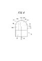
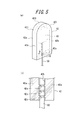
- FIG. 5 (a) is a perspective view which shows the detection part and inner cover of FIG.
- FIG. 5B is a cross-sectional view of the main part of the inner cover along the line BB shown in FIG. It is a perspective view which shows the modification of an outer side cover.
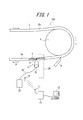
- FIG. 1 is a side view showing a state in which the monitoring system 100 is used for a conveyor belt 2, and a part of the conveyor belt 2 is also referred to as a longitudinal direction of the conveyor belt 2 (hereinafter, simply “belt longitudinal direction”). ).
- 2 is a front view of the monitoring system 100 as viewed from the left side of FIG. 1, and the lower portion of the conveyor belt 2 is a cross section along the width direction of the conveyor belt 2 (hereinafter also simply referred to as “belt width direction”). Is shown.
- the conveyor belt 2 is an annular belt wound around the pulley 1, and transports transported goods (iron ore, coal, etc.) in the upper carrier side portion 2 b of the conveyor belt 2 portions facing each other in the vertical direction. To do.
- the lower part of the conveyor belt 2 is a return side part 2a that does not transport the transported goods.
- the monitoring system 100 includes a rubber magnet 3 (object to be detected) embedded in a rubber member of the conveyor belt 2 and a return side portion 2a of the conveyor belt 2 near the end in the extending direction of the conveyor belt 2 in this example. And a magnetic sensor 4 (sensor) disposed on the lower side.
- the magnetic sensor 4 detects the magnetic field of the rubber magnet 3 when the rubber magnet 3 passes above the magnetic sensor 4 while the conveyor belt 2 is running.
- the wear state of the conveyor belt 2 is monitored based on the detection signal from the magnetic sensor 4.
- “lower side with respect to the return side portion 2a” means that at least a part (all in this example) of the magnetic sensor 4 is in the downward projection plane of the return side portion 2a.
- the rubber magnet 3 is formed in a substantially flat plate shape, and is a conveyor belt rather than a reinforcing material 5 (steel cord or the like) extending over the entire circumference inside the rubber member of the conveyor belt 2.
- 2 on the outer peripheral side (hereinafter, also simply referred to as “belt outer peripheral side”), and is arranged in a state inclined with respect to the horizontal direction over the entire length in the belt width direction.
- the end of the rubber magnet 3 on the belt outer peripheral side is disposed in the same plane as the outer peripheral surface of the conveyor belt 2, and is also referred to as the inner peripheral side of the conveyor belt 2 of the rubber magnet 3 (hereinafter simply referred to as “belt inner peripheral side”).
- traveling direction A Is the rear side (right side in FIG. 1) of the traveling direction A (hereinafter also simply referred to as “traveling direction A”) of the return side portion 2a of the conveyor belt 2 rather than the end of the rubber magnet 3 on the belt outer peripheral side.
- traveling direction A Is the rear side (right side in FIG. 1) of the traveling direction A (hereinafter also simply referred to as “traveling direction A”) of the return side portion 2a of the conveyor belt 2 rather than the end of the rubber magnet 3 on the belt outer peripheral side.
- the rubber magnet 3 for example, a magnet obtained by magnetizing a bonded magnet in which a magnetic powder is dispersed and mixed in a rubber matrix and formed into a sheet shape in the thickness direction can be used.
- rare earth magnets such as ferrite, neodymium iron boron, and samarium iron nitrogen, and alco magnets can be used.
- the magnetic sensor 4 has a belt on the front side in the traveling direction A (left side in FIG. 1) rather than the scraper 6 that scrapes off the fragments of the transported material transported by the carrier side portion 2 b of the conveyor belt 2. It is fixed to a sensor fixing frame 35 extending in the width direction. The configuration of the magnetic sensor 4 will be described in detail later.
- both ends of the sensor fixing frame 35 in the belt width direction are fixed to a pair of conveyor frames 34 that support the conveyor belt 2 on both sides of the belt width direction of the conveyor belt 2 so that the belt can run freely.
- the sensor fixing frame 35 is maintained at a predetermined height with respect to the ground.
- the monitoring system 100 of the present example is further disposed at a position away from the field calculation control unit 10 and the field calculation control unit 10 connected to the magnetic sensor 4 via the electric cable 50.
- a central control unit 13 capable of wireless communication with the on-site arithmetic control unit 10 is further provided.
- the on-site calculation control unit 10 calculates the degree of wear of the conveyor belt 2 based on the received detection signal, and transmits the calculation result by the transmission unit 9.
- the central control unit 13 receives the signal from the field calculation control unit 10 by the reception unit 11, performs various calculations based on the received signal, and outputs the calculation results to the output terminal 12 (personal computer or the like). Or, based on the calculation result, when it is determined that the degree of wear exceeds a predetermined threshold, a warning is issued or the traveling of the conveyor belt 2 is stopped.
- the magnetic sensor 4 includes a detection unit 40 (eight in the illustrated example) and at least the upper part (in this example, the lower part, the upper part, and the upper part) of all the detection parts 40.
- the detection unit 40 is configured by an electronic circuit board such as an MI (Magnetic Magnetic Inductive) sensor, a Hall sensor, a loop coil sensor, and the like, and bears a detection function of the rubber magnet 3 in the magnetic sensor 4.
- the detection units 40 are arranged at equal intervals (for example, 100 mm) in the belt width direction so as not to affect each other's sensitivity, and the detection signals from the detection units 40 are respectively It is output to the on-site calculation control unit 10 via the electric cable 50.
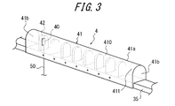
- the monitoring system 100 grasps the wear state of the conveyor belt 2 at the belt width direction position corresponding to each detection unit 40 based on the output waveform obtained from each detection unit 40. 2 and 3, only the detection unit 40 accommodated in one inner cover 42 and the electric cable 50 connected thereto are shown for simplification of the drawings.
- the corresponding detection units 40 and electric cables 50 are omitted from the illustration.
- the inner cover 42 is made of, for example, a resin such as polycarbonate, and seals the detection unit 40 in order to protect the detection unit 40 from moisture and dirt.
- the inner cover 42 is formed in a substantially plate shape. More specifically, the outer surface of the inner cover 42 has a substantially rectangular shape (in the example of the figure, a rectangular shape that is long in the belt longitudinal direction and short in the belt width direction). It has a horizontal cross section.
- the upper surface of the inner cover 42 has a shape in which the curved shape is curved upward and convex along the belt width direction in a virtual plane including the belt longitudinal direction and the vertical direction. ing.
- the bottom surface of the inner cover 42 is disposed on the upper surface of the sensor fixing frame 35, and the upper end of the inner cover 42 is close to or in contact with the inner surface of the outer cover 41 (in the example shown in the figure).
- the electric cable 50 extends downward from the lower end of the detection unit 40 inside the inner cover 42, exits from the bottom surface of the inner cover 42 to the outside of the inner cover 42, and is formed in the sensor fixing frame 35. (Not shown) extends further down.
- the inner cover 42 in this example has a pair of panels 42a facing each other in the width direction (perpendicular to the paper surface in FIG. 4; belt width direction). It is formed by being bonded together by ultrasonic welding or the like while being accommodated inside. In a state where the pair of panels 42a are bonded together, the inner cover 42 forms an accommodation space for accommodating the detection unit 40 and the end portion of the electric cable 50 on the inner cover 42 side substantially without any gap.
- the inner wall surface 42b of the inner cover 42 that divides the housing space has a shape that is substantially compatible with the end portion on the inner cover 42 side of the detection unit 40 and the electric cable 50, and has a slightly larger dimension than these. .
- the detection unit 40 and the end portion of the electric cable 50 on the inner cover 42 side are accommodated in the inner cover 42, there is almost no air in the inner cover 42, and the detection unit 40 substantially.
- the end of the electric cable 50 on the inner cover 42 side are embedded in a material (resin or the like) constituting the inner cover 42.
- the outer surface of the inner cover 42 has a substantially rectangular horizontal cross section, so that, for example, the inner cover 42 is formed and thus a magnetic sensor, as compared with the case where the outer surface has a substantially circular horizontal cross section. 4 is easy to manufacture.
- FIG. 5B is a longitudinal sectional view of the inner cover 42 and the electric cable 50 taken along the line BB in FIG. 5A.
- the inner wall 42 b of the inner cover 42 that divides the accommodation space has a lower portion surrounding the electric cable 50 toward the inner peripheral side of the electric cable 50.
- a protruding annular rib 42c is formed.
- a plurality (more specifically, three) annular ribs 42c are formed to be spaced apart from each other in the vertical direction.
- the inner diameter of the annular rib 42 c is set smaller than the outer diameter of the electric cable 50.
- the annular rib 42 c bites into the electric cable 50 in a state where the electric cable 50 is accommodated in the accommodation space of the inner cover 42, so that the detection unit 40 and the inner cover 42 of the electric cable 50 can be more sure.
- the side end portion can be sealed in the inner cover 42 to prevent foreign matter from entering the inner cover 42.
- the outer cover 41 is made of, for example, a resin such as PET, FRP, or the like, and extends in the belt width direction along most of the conveyor belt 2 in the belt width direction.
- a cover plate 41a which is bent in a substantially inverted U shape so as to straddle the inner cover 42, and has lower ends on both sides in the belt longitudinal direction fixed to the sensor fixing frame 35, and substantially on both sides of the cover plate 41a in the belt width direction.
- a pair of end plate portions 41 b that close the gap between the inverted U-shaped end edge and the upper surface of the sensor fixing frame 35 are provided.
- the cover plate portion 41a and the pair of end plate portions 41b may be configured separately and fixed to each other by adhesion or the like, or may be integrally formed.
- the outer cover 41 covers at least the upper parts of all the inner covers 42 (and thus at least the upper parts of all the detection units 40), so that the package falls from the outer surface of the return side portion 2 a of the conveyor belt 2. It is possible to prevent debris from accumulating between the inner covers 42 (and thus between the detection units 40).
- the upper surface of the outer cover 41 has a shape in which the curved shape is curved upward and convex along the belt width direction in a virtual plane including the belt longitudinal direction and the vertical direction. ing. Therefore, the outer cover 41 has a descending surface 411 that continuously extends downward from the uppermost portion 410 (upper end) of the outer cover 41 toward the outer side in the horizontal direction (in this example, both sides in the belt longitudinal direction). Since the outer cover 41 has the descending surface 411, even if the scrap of the transported material adhered to the outer surface of the return side portion 2 a of the conveyor belt 2 falls on the outer cover 41, the scrap is along the descending surface 411.
- “continuously” extending downward refers to extending downward without extending in the horizontal direction in the middle of the extension, and in the form of an upwardly convex arc as in this example
- “continuously” extending downward refers to extending downward without extending in the horizontal direction in the middle of the extension, and in the form of an upwardly convex arc as in this example
- extending downward in a concave arc shape on the upper side extending downward in a curved shape while changing the radius of curvature and the direction of irregularities on the upper side, or linearly horizontal
- the case of extending downward with an inclination with respect to the direction and the vertical direction the inclination may change one or more times during the extension).
- the upper surface of the outer cover 41 has a descending surface 411 that linearly extends downward from the uppermost portion 410 of the outer cover 41 toward both sides in the belt longitudinal direction
- the upper surface of the outer cover 41 is It becomes a substantially triangular shape in a virtual plane including the longitudinal direction and the vertical direction, and in such a case as well, accumulation of debris on the magnetic sensor 4 can be suppressed.
- the descending surface 411 only needs to continuously extend downward from the uppermost portion 410 of the outer cover 41 toward the outer side in the horizontal direction.
- the outer cover 41 may extend continuously downward on both sides in the belt width direction from the uppermost portion 410 toward the outer side in the belt width direction. Further, from the viewpoint of suppressing the accumulation of debris on the magnetic sensor 4, it is preferable that the upper surface of the outer cover 41 does not include a flat surface along the horizontal direction or a concave surface recessed downward.
- the magnetic sensor 4 (more specifically, the outer cover 41) and the return side portion 2 a of the conveyor belt 2 are caused when the conveyor belt 2 vibrates. The impact at the time of contact can be reduced, and as a result, damage to the magnetic sensor 4 can be prevented.
- the rear portion of the descending surface 411 from the uppermost portion 410 of the outer cover 41 in the traveling direction A is the present example.
- the belt is smoothly curved in the longitudinal direction of the belt.
- the radius of curvature (for example, 40 mm) of the arc-shaped inner surface (lower surface) of the cover plate portion 41a of the outer cover 41 is set on the inner side in a virtual plane including the belt longitudinal direction and the vertical direction.
- the radius of curvature of the arcuate upper surface of the cover 42 is set to be greater than or equal to 20 mm, for example.
- the vertical distance d between the uppermost portion 410 of the outer cover 41 and the outer surface of the return side portion 2a of the conveyor belt 2 is such that the two do not come into contact with each other due to slight vibration that can normally occur in the conveyor belt 2. It is set as small as possible (for example, 20 mm). With such a configuration, the distance d ′ in the vertical direction between the upper end of the detection unit 40 and the outer surface of the return side portion 2a of the conveyor belt 2 is made sufficiently small (for example, 30 mm), and the rubber by the detection unit 40 The detection capability of the magnet 3 can be fully exhibited.
- each detection unit 40 may be covered only with the single outer cover 41.
- the vertical distance d ′ between the upper end of the detection unit 40 and the outer surface of the return side portion 2a of the conveyor belt 2 can be further reduced.
- each inner cover 42 continuously lowers downward from the respective uppermost portion 420 toward the outer side in the horizontal direction (in the illustrated example, both sides in the belt longitudinal direction).
- the extending descending surface 421 it is possible to suppress the accumulation of debris on the inner cover 42 and thus the magnetic sensor 4.
- at least a part (a part in the example in the figure) of the descending surface 421 of the inner cover 42 is directed rearward in the traveling direction A from the uppermost part 420 of the inner cover 42. Accordingly, if the belt is continuously extended downward, the impact when the inner cover 42 and thus the magnetic sensor 4 and the return side portion 2a of the conveyor belt 2 come into contact with each other during vibration of the conveyor belt 2 can be reduced.
- each outer cover 41 covers at least the upper part of a plurality (preferably 2 to 3) of detection units 40.
- the eight detection units 40 included in the magnetic sensor 4 are each covered with an inner cover 42, and three outer covers 41 arranged adjacent to each other in the width direction of the conveyor belt 2.
- Each outer cover 41 covers two or three detectors 40, respectively.
- each outer side is compared with the case of covering with a single outer cover 41 as in the example of FIG. 3. Since the strength of the cover 41 can be increased, the outer cover 41 and the magnetic sensor 4 can be damaged when the outer cover 41 and the return side portion 2a of the conveyor belt 2 come into contact with each other when the conveyor belt 2 vibrates. Can be suppressed more effectively.
- the present invention can be used for, for example, a sensor and a monitoring system used for monitoring the wear state of a conveyor belt.
Landscapes
- Engineering & Computer Science (AREA)
- Mechanical Engineering (AREA)
- Chemical & Material Sciences (AREA)
- Analytical Chemistry (AREA)
- General Health & Medical Sciences (AREA)
- Physics & Mathematics (AREA)
- Health & Medical Sciences (AREA)
- Life Sciences & Earth Sciences (AREA)
- Chemical Kinetics & Catalysis (AREA)
- Biochemistry (AREA)
- Electrochemistry (AREA)
- General Physics & Mathematics (AREA)
- Immunology (AREA)
- Pathology (AREA)
- Control Of Conveyors (AREA)
- Measurement Of Length, Angles, Or The Like Using Electric Or Magnetic Means (AREA)
- Length Measuring Devices With Unspecified Measuring Means (AREA)
- Geophysics And Detection Of Objects (AREA)
Priority Applications (5)
| Application Number | Priority Date | Filing Date | Title |
|---|---|---|---|
| JP2015558788A JP6645833B2 (ja) | 2014-01-27 | 2015-01-26 | センサー及びモニタリングシステム |
| US15/109,492 US9766208B2 (en) | 2014-01-27 | 2015-01-26 | Sensor, and monitoring system |
| AU2015210253A AU2015210253B2 (en) | 2014-01-27 | 2015-01-26 | Sensor and monitoring system |
| EP15740903.8A EP3100965B1 (de) | 2014-01-27 | 2015-01-26 | Sensor und überwachungssystem |
| CN201580005850.3A CN105934397B (zh) | 2014-01-27 | 2015-01-26 | 传感器和监测系统 |
Applications Claiming Priority (2)
| Application Number | Priority Date | Filing Date | Title |
|---|---|---|---|
| JP2014-012373 | 2014-01-27 | ||
| JP2014012373 | 2014-01-27 |
Publications (1)
| Publication Number | Publication Date |
|---|---|
| WO2015111418A1 true WO2015111418A1 (ja) | 2015-07-30 |
Family
ID=53681228
Family Applications (1)
| Application Number | Title | Priority Date | Filing Date |
|---|---|---|---|
| PCT/JP2015/000328 Ceased WO2015111418A1 (ja) | 2014-01-27 | 2015-01-26 | センサー及びモニタリングシステム |
Country Status (6)
| Country | Link |
|---|---|
| US (1) | US9766208B2 (de) |
| EP (1) | EP3100965B1 (de) |
| JP (1) | JP6645833B2 (de) |
| CN (1) | CN105934397B (de) |
| AU (1) | AU2015210253B2 (de) |
| WO (1) | WO2015111418A1 (de) |
Cited By (1)
| Publication number | Priority date | Publication date | Assignee | Title |
|---|---|---|---|---|
| WO2017157683A1 (de) * | 2016-03-17 | 2017-09-21 | Khs Gmbh | Behälterbehandlungsanlage |
Families Citing this family (8)
| Publication number | Priority date | Publication date | Assignee | Title |
|---|---|---|---|---|
| JP6432291B2 (ja) * | 2014-11-10 | 2018-12-05 | 横浜ゴム株式会社 | コンベヤベルトの摩耗モニタリングシステム |
| JP6011677B1 (ja) * | 2015-04-30 | 2016-10-19 | 横浜ゴム株式会社 | コンベヤベルトの摩耗モニタリングシステム |
| DE102015209357A1 (de) * | 2015-05-21 | 2016-11-24 | Ifm Electronic Gmbh | Vorrichtung zur Gurtrissüberwachung bei einem Förderband |
| CN107697598A (zh) * | 2017-10-12 | 2018-02-16 | 中煤张家口煤矿机械有限责任公司 | 一种变频刮板输送机智能调速控制系统 |
| CN107915022A (zh) * | 2017-11-20 | 2018-04-17 | 龙口矿业集团有限公司 | 强力皮带机第九种皮带保护装置 |
| CN112789182A (zh) * | 2018-10-05 | 2021-05-11 | 株式会社普利司通 | 轮胎磨损估计方法 |
| US10988348B1 (en) * | 2020-05-26 | 2021-04-27 | Otis Elevator Company | Escalator steps with strain sensors |
| AU2023250380A1 (en) * | 2022-04-05 | 2024-10-17 | Flexible Steel Lacing Company | Monitoring system for conveyor belt ancillary devices |
Citations (4)
| Publication number | Priority date | Publication date | Assignee | Title |
|---|---|---|---|---|
| JPH11301842A (ja) * | 1998-04-22 | 1999-11-02 | Toyo Kanetsu Kk | 載せ込みコンベヤ |
| JP2004259455A (ja) * | 2003-02-24 | 2004-09-16 | Alps Electric Co Ltd | 磁気スイッチ |
| JP2011069617A (ja) * | 2009-09-23 | 2011-04-07 | Sumitomo Wiring Syst Ltd | 回転検出装置およびその製造方法 |
| WO2011058755A1 (ja) | 2009-11-11 | 2011-05-19 | 株式会社ブリヂストン | コンベアベルト摩耗検出装置 |
Family Cites Families (17)
| Publication number | Priority date | Publication date | Assignee | Title |
|---|---|---|---|---|
| US4621727A (en) | 1985-08-13 | 1986-11-11 | The Goodyear Tire & Rubber Company | Conveyor belt damage sensor |
| US5500641A (en) * | 1994-07-22 | 1996-03-19 | Glens'son | Safety switch device for use in manufacture of round cylindrical vessels |
| US5957263A (en) * | 1996-09-25 | 1999-09-28 | Advanced Robotic Technologies, Inc. | Apparatus for correcting for wear of a conveyor belt |
| JPH1179336A (ja) * | 1997-09-16 | 1999-03-23 | Daifuku Co Ltd | 駆動ローラコンベヤ |
| CN2430403Y (zh) * | 2000-07-26 | 2001-05-16 | 边锁 | 非接触式电子皮带保护装置 |
| DE10231902A1 (de) * | 2002-07-11 | 2004-02-12 | Demag Cranes & Components Gmbh | Steuereinrichtung für flurfreie Förderer |
| US7982764B2 (en) * | 2008-07-08 | 2011-07-19 | United Parcel Service Of America, Inc. | Apparatus for monitoring a package handling system |
| DE102008061729A1 (de) * | 2008-12-12 | 2010-06-24 | Rwe Power Ag | Fördergut, Schlitzschutzsystem und Verfahren zur Erkennung und Erfassung von Längsschlitzen in einem Fördergut |
| JP5264562B2 (ja) * | 2009-03-02 | 2013-08-14 | ユニ・チャーム株式会社 | 吸収性物品の製造装置及び製造方法 |
| US8641942B2 (en) * | 2010-05-12 | 2014-02-04 | Corning Incorporated | Laser scanning systems and methods for measuring extruded ceramic logs |
| IT1403497B1 (it) * | 2010-12-27 | 2013-10-17 | Makro Labelling Srl | "dispositivo di rilevamento per contenitori in movimento" |
| DE102011000025A1 (de) * | 2011-01-04 | 2012-07-05 | Wincor Nixdorf International Gmbh | Vorrichtung zum Erfassen von Waren |
| ITMI20111537A1 (it) * | 2011-08-12 | 2013-02-13 | Rexnord Marbett Srl | Sistema di monitoraggio per catene di trasporto di trasportatori di articoli |
| CN102992000A (zh) * | 2012-10-05 | 2013-03-27 | 昆山特力伯传动科技有限公司 | 输送带异常检测装置 |
| US9435076B2 (en) * | 2012-10-10 | 2016-09-06 | Xyleco, Inc. | Processing materials |
| US9533831B2 (en) * | 2015-03-30 | 2017-01-03 | David W. Nelson | Conveyor belt monitor |
| US9440799B1 (en) * | 2016-06-01 | 2016-09-13 | Finetek Co., Ltd. | Conveying apparatus |
-
2015
- 2015-01-26 WO PCT/JP2015/000328 patent/WO2015111418A1/ja not_active Ceased
- 2015-01-26 US US15/109,492 patent/US9766208B2/en not_active Expired - Fee Related
- 2015-01-26 AU AU2015210253A patent/AU2015210253B2/en not_active Ceased
- 2015-01-26 CN CN201580005850.3A patent/CN105934397B/zh not_active Expired - Fee Related
- 2015-01-26 JP JP2015558788A patent/JP6645833B2/ja not_active Expired - Fee Related
- 2015-01-26 EP EP15740903.8A patent/EP3100965B1/de not_active Not-in-force
Patent Citations (4)
| Publication number | Priority date | Publication date | Assignee | Title |
|---|---|---|---|---|
| JPH11301842A (ja) * | 1998-04-22 | 1999-11-02 | Toyo Kanetsu Kk | 載せ込みコンベヤ |
| JP2004259455A (ja) * | 2003-02-24 | 2004-09-16 | Alps Electric Co Ltd | 磁気スイッチ |
| JP2011069617A (ja) * | 2009-09-23 | 2011-04-07 | Sumitomo Wiring Syst Ltd | 回転検出装置およびその製造方法 |
| WO2011058755A1 (ja) | 2009-11-11 | 2011-05-19 | 株式会社ブリヂストン | コンベアベルト摩耗検出装置 |
Non-Patent Citations (1)
| Title |
|---|
| See also references of EP3100965A4 |
Cited By (1)
| Publication number | Priority date | Publication date | Assignee | Title |
|---|---|---|---|---|
| WO2017157683A1 (de) * | 2016-03-17 | 2017-09-21 | Khs Gmbh | Behälterbehandlungsanlage |
Also Published As
| Publication number | Publication date |
|---|---|
| CN105934397B (zh) | 2018-08-31 |
| JP6645833B2 (ja) | 2020-02-14 |
| AU2015210253B2 (en) | 2017-10-19 |
| EP3100965B1 (de) | 2018-05-02 |
| EP3100965A1 (de) | 2016-12-07 |
| AU2015210253A1 (en) | 2016-07-21 |
| US9766208B2 (en) | 2017-09-19 |
| EP3100965A4 (de) | 2017-04-05 |
| JPWO2015111418A1 (ja) | 2017-03-23 |
| US20160327517A1 (en) | 2016-11-10 |
| CN105934397A (zh) | 2016-09-07 |
Similar Documents
| Publication | Publication Date | Title |
|---|---|---|
| WO2015111418A1 (ja) | センサー及びモニタリングシステム | |
| JPWO2015111418A6 (ja) | センサー及びモニタリングシステム | |
| AU2017227277B2 (en) | Wear detection device for conveyor belt | |
| US9096103B2 (en) | Monitoring device for tyres for vehicle wheels, tyre for vehicle wheels provided with said monitoring device, and method for installing an electronic unit in said tyre | |
| ES2216977T3 (es) | Dispositivo para la vigilancia de una instalacion de transporte. | |
| KR101786282B1 (ko) | 트로프, 포장 구조체, 및 포장 구조체의 시공 방법 | |
| EP2386505A1 (de) | Förderband | |
| JP2006315858A (ja) | コンベヤベルトの摩耗検出装置 | |
| WO2006078691A3 (en) | Integrated detection and monitoring system | |
| EP2916109B1 (de) | Magnetische Abschirmungsabdeckung für magnetischen Codierer und magnetischer Codierer | |
| JP2010052927A (ja) | コンベヤベルトのモニタリングシステム | |
| JP2012046328A (ja) | コンベアベルトの縦裂き検知装置 | |
| CN203196699U (zh) | 橡塑磁性衬板模块 | |
| JP2005138979A (ja) | コンベアベルトの摩耗度合測定方法およびコンベアベルト摩耗度合測定装置。 | |
| ZA201908007B (en) | Ultrasonic detection system and method | |
| US20080309026A1 (en) | Dust Sealing | |
| JP2010143748A (ja) | エスカレーター用防水カバーおよびエスカレーター用防水カバーの固定部材 | |
| KR20090022505A (ko) | 센서용 커버유닛 | |
| CN205332996U (zh) | 轮衬磨损检测装置 | |
| JP2016185879A (ja) | スチールコードコンベヤベルトの縦裂検出装置及びスチールコードコンベヤベルトの縦裂検出システム | |
| CN203235558U (zh) | 磁选机皮带 | |
| JP2011038326A (ja) | 可搬型注意喚起マット及び注意喚起システム | |
| KR20110021080A (ko) | 와이어 흔들림 감지장치 | |
| KR101496416B1 (ko) | 케이블 손상 방지 기능을 갖는 원료 불출기 | |
| JP2009154970A (ja) | パイプコンベヤ |
Legal Events
| Date | Code | Title | Description |
|---|---|---|---|
| 121 | Ep: the epo has been informed by wipo that ep was designated in this application |
Ref document number: 15740903 Country of ref document: EP Kind code of ref document: A1 |
|
| ENP | Entry into the national phase |
Ref document number: 2015558788 Country of ref document: JP Kind code of ref document: A |
|
| WWE | Wipo information: entry into national phase |
Ref document number: 15109492 Country of ref document: US |
|
| REEP | Request for entry into the european phase |
Ref document number: 2015740903 Country of ref document: EP |
|
| WWE | Wipo information: entry into national phase |
Ref document number: 2015740903 Country of ref document: EP |
|
| ENP | Entry into the national phase |
Ref document number: 2015210253 Country of ref document: AU Date of ref document: 20150126 Kind code of ref document: A |
|
| NENP | Non-entry into the national phase |
Ref country code: DE |