WO2015111455A1 - Fil en alliage à base de cuivre et de fer pour une broche de connecteur et connecteur - Google Patents
Fil en alliage à base de cuivre et de fer pour une broche de connecteur et connecteur Download PDFInfo
- Publication number
- WO2015111455A1 WO2015111455A1 PCT/JP2015/050564 JP2015050564W WO2015111455A1 WO 2015111455 A1 WO2015111455 A1 WO 2015111455A1 JP 2015050564 W JP2015050564 W JP 2015050564W WO 2015111455 A1 WO2015111455 A1 WO 2015111455A1
- Authority
- WO
- WIPO (PCT)
- Prior art keywords
- wire
- connector
- connector pin
- connector pins
- alloy wire
- Prior art date
- Legal status (The legal status is an assumption and is not a legal conclusion. Google has not performed a legal analysis and makes no representation as to the accuracy of the status listed.)
- Ceased
Links
Images

Classifications
-
- C—CHEMISTRY; METALLURGY
- C22—METALLURGY; FERROUS OR NON-FERROUS ALLOYS; TREATMENT OF ALLOYS OR NON-FERROUS METALS
- C22C—ALLOYS
- C22C9/00—Alloys based on copper
-
- C—CHEMISTRY; METALLURGY
- C22—METALLURGY; FERROUS OR NON-FERROUS ALLOYS; TREATMENT OF ALLOYS OR NON-FERROUS METALS
- C22C—ALLOYS
- C22C38/00—Ferrous alloys, e.g. steel alloys
-
- C—CHEMISTRY; METALLURGY
- C22—METALLURGY; FERROUS OR NON-FERROUS ALLOYS; TREATMENT OF ALLOYS OR NON-FERROUS METALS
- C22C—ALLOYS
- C22C38/00—Ferrous alloys, e.g. steel alloys
- C22C38/16—Ferrous alloys, e.g. steel alloys containing copper
-
- H—ELECTRICITY
- H01—ELECTRIC ELEMENTS
- H01B—CABLES; CONDUCTORS; INSULATORS; SELECTION OF MATERIALS FOR THEIR CONDUCTIVE, INSULATING OR DIELECTRIC PROPERTIES
- H01B1/00—Conductors or conductive bodies characterised by the conductive materials; Selection of materials as conductors
- H01B1/02—Conductors or conductive bodies characterised by the conductive materials; Selection of materials as conductors mainly consisting of metals or alloys
- H01B1/026—Alloys based on copper
Definitions
- the present invention relates to a Cu—Fe alloy wire for connector pins and a connector having a connector pin using the same.
- Some connectors such as automobile PCB (Printed Circuit Board) connectors and automobile relay connectors are provided with connector pins made of a copper alloy in which a metal of several mass% is added to copper, such as brass.
- a connector pin that has higher rigidity and can reduce material costs in order to reduce the weight, size, and cost of the entire connector. Therefore, it has been studied to use a Cu—Fe based alloy in which Fe (iron) is added to Cu (copper) as a material for connector pins as a copper alloy having high material strength and low material cost.
- Patent Document 1 discloses an example of a spring member made of an alloy of 10 to 70% by mass of Fe in which 0.05 to 5% by mass of carbon is dissolved, and the balance being Cu and inevitable impurities.
- a Cu—Fe-based alloy having such a chemical component tends to have a higher strength than conventional copper alloys.
- the Cu—Fe-based alloy contains Fe, which is cheaper than metal, than Cu, the material cost can be easily reduced by increasing the Fe content.
- the Cu—Fe-based alloy is a material having a possibility of achieving both sufficient strength as a material for the connector pin and material cost.
- Cu—Fe based alloys with an increased Fe content tend to increase in strength and reduce the material cost, but there is a problem that workability during bending is deteriorated. Therefore, a Cu—Fe alloy having high strength is likely to crack at the bent portion after bending in the connector pin manufacturing process.
- the present invention has been made in view of such a background, and provides a Cu—Fe-based alloy wire for a connector pin that is excellent in both workability and strength and is low in material cost, and a connector having a connector pin using the same. It is something to try.
- One aspect of the present invention contains 10 mass% or more of Fe, with the remainder having chemical components consisting of Cu and inevitable impurities, Fe-based particles that have Fe as a main component and have a fibrous shape extending in the wire drawing direction have a metal structure distributed in a Cu-based matrix having Cu as a main component, The Fe-based particles have an average width obtained by measuring in a direction perpendicular to the wire drawing direction of 0.5 ⁇ m or less, and a length obtained by measuring in a direction parallel to the wire drawing direction.
- the Cu—Fe alloy wire for connector pins is characterized in that the average value of is 4 ⁇ m or more.
- Another aspect of the present invention is a connector having a connector pin made of the above-described Cu—Fe alloy wire for connector pin.
- the above-mentioned Cu—Fe alloy wire for connector pins (hereinafter sometimes abbreviated as “wire” as appropriate) contains 10% by mass or more of Fe, and the remainder has a chemical component composed of Cu and inevitable impurities. ing. Therefore, the said wire can easily implement
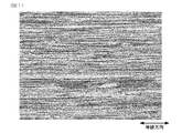
- the wire has a metal structure in which Fe-based particles having a fibrous shape extending in the wire drawing direction are distributed in a Cu-based matrix having Cu as a main component.
- the Fe-based particles have an average width obtained by measuring in a direction perpendicular to the wire drawing direction of 0.5 ⁇ m or less, and are obtained by measuring in a direction parallel to the wire drawing direction.
- the average length is 4 ⁇ m or more.
- the wire since the wire has a Cu-based parent phase containing Cu as a main component, it is possible to easily ensure a conductivity equal to or higher than that of a conventional copper alloy. Moreover, the said wire can be Sn-plated in order to improve solder wettability. As a result, the wire can satisfy the electrical characteristics required for the connector pin.
- the wire can have higher strength than the conventional copper alloy by including the specific chemical component and the metal structure described above.
- the above-described Cu—Fe alloy wire for connector pins is excellent in both workability and strength, and is low in material cost.
- the connector pin produced from the wire is less likely to be cracked or cracked in the bent portion formed by bending. As a result, the connector having the connector pin has excellent quality.
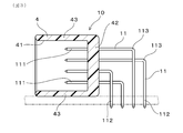
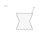
- FIG. 3 is a cross-sectional view taken along line III-III in FIG. 2. Sectional drawing of the connector pin which made the cross-sectional shape into substantially rectangular shape in Example 2. FIG. Sectional drawing of the connector pin which made the cross-sectional shape trapezoid in Example 2. FIG. Sectional drawing of the connector pin which exhibits the cross-sectional shape which indented the center part of the end surface which mutually faces in the square-shaped cross section in Example 2 inside.
- the above-mentioned Cu—Fe alloy wire for connector pins contains 10% by mass or more of Fe.
- the strength of Cu—Fe-based alloys tends to increase as the Fe content increases. Therefore, the said wire can fully satisfy the intensity
- the said wire can reduce material cost rather than the conventional copper alloy by content of Fe being 10 mass% or more. Therefore, from the viewpoint of increasing the strength and reducing the material cost, the Fe content is set to 10% by mass or more. From the same viewpoint, the Fe content is preferably 20% by mass or more, and more preferably 50% by mass or more.
- the Fe content is preferably regulated to 70% by mass or less, and the Fe content is more preferably regulated to 60% by mass or less.
- the above-described Cu—Fe-based alloy wire for connector pins has a Fe content of 10 mass% or more, preferably 10 to 70 mass%, more preferably 10 to 60 mass%. It satisfies various properties such as strength, workability, and conductivity required for the pin material, and is a material with low material cost.
- the metal structure includes, for example, a crystallized substance mainly composed of Fe generated during casting or a precipitate mainly composed of Fe generated by heat treatment or the like in a state where the Cu is stretched in a wire drawing direction.
- a crystallized substance mainly composed of Fe generated during casting or a precipitate mainly composed of Fe generated by heat treatment or the like in a state where the Cu is stretched in a wire drawing direction.
- the crystallized product and the precipitate are plastically deformed so as to be stretched in the wire drawing direction by receiving a working force during cold working such as cold drawing or cold rolling.
- the Fe-based particles extending in the wire drawing direction are generated.
- the above-mentioned “main component” means that the element has the highest content.
- the Cu-based matrix may contain a trace amount of Fe or impurities in addition to the main component Cu.
- the Fe-based particles may contain a trace amount of Cu or impurities in addition to the main component Fe.
- the Fe-based particles have an average width obtained by measuring in a direction perpendicular to the drawing direction of 0.5 ⁇ m or less, and a length obtained by measuring in a direction parallel to the drawing direction.
- the average value is 4 ⁇ m or more.
- the effect of improving the strength by the Fe-based particles may be insufficient, and the strength of the wire may be insufficient.
- both the Fe-based particles having a width exceeding 1 ⁇ m and the Fe-based particles having a width of less than 0.1 ⁇ m it is preferable to reduce the contents of both the Fe-based particles having a width exceeding 1 ⁇ m and the Fe-based particles having a width of less than 0.1 ⁇ m. From the same viewpoint, it is more preferable to control the metal structure so that the average width of the Fe-based particles is in the range of 0.1 to 0.5 ⁇ m.
- the metal structure may be non-uniform.
- heterogenous metal structure becomes easy to produce stress concentration at the time of a bending process, and there exists a possibility that workability may deteriorate. From the viewpoint of making the metal structure of the wire uniform and improving the workability, it is preferable to control the metal structure so that the average value of the length is 30 ⁇ m or less.
- both the Fe-based particles having a length of more than 30 ⁇ m and the Fe-based particles having a length of less than 4 ⁇ m it is preferable to reduce the contents of both the Fe-based particles having a length of more than 30 ⁇ m and the Fe-based particles having a length of less than 4 ⁇ m. From the same viewpoint, it is more preferable to control the metal structure so that the average length of the Fe-based particles is in the range of 4 to 30 ⁇ m.
- the size of the Fe-based particles can be controlled, for example, by adjusting the size of precipitates or crystallized matter generated during casting or the like, or adjusting the processing rate in the wire drawing process.
- the wire has a tensile strength of 700 MPa or more.
- the Cu—Fe-based alloy wire for the connector pin includes a brass material (tensile strength of 450 to 500 MPa) or a Corson-based copper alloy (with a tensile strength of 450 to 500 MPa) by including both the specific chemical component and the specific metal structure.
- the tensile strength is higher than 600 to 650 MPa, and the processability is excellent. Therefore, even if the wire diameter is further reduced, the wire has sufficient strength as a material for the connector pin, which is advantageous for reducing the size and weight of the entire connector.
- the wire preferably has an elongation of 2% or more.
- the said wire since the said wire becomes a thing with high ductility enough, when performing a bending process, it becomes easier to suppress generation
- the wire has a conductivity of 30% IACS or higher.
- the said wire has the electrical conductivity equivalent to copper alloys, such as a brass material. Therefore, the said wire can satisfy the electrical conductivity requested
- the wire may have a rectangular cross section perpendicular to the wire drawing direction.
- a conventional square wire using a copper alloy needs to be shaped so that the cross section perpendicular to the wire drawing direction has a square shape.
- the Cu—Fe-based alloy wire for connector pins has a higher strength than conventional copper alloys, and is required for connector pins even if the cross section perpendicular to the wire drawing direction is formed into a rectangular shape. Sufficient rigidity can be ensured.
- the connector pin having a rectangular cross-section has an arrangement space compared to a connector pin having a square cross-section by arranging a plurality of connector pins in a row with the long sides in the cross-section facing each other.
- the space can be saved.
- the wire material can more easily save the space for arranging the connector pins, which is advantageous for reducing the size and weight of the entire connector.
- Example 1 An embodiment of the connector pin Cu—Fe alloy wire will be described with reference to FIG.
- a Cu—Fe-based alloy wire for connector pins (hereinafter sometimes abbreviated as “wire” as appropriate) contains 10% by mass or more of Fe, and the remainder has a chemical component composed of Cu and inevitable impurities.
- the wire has a metal structure in which Fe-based particles having Fe as a main component and a fibrous shape extending in the drawing direction are distributed in a Cu-based matrix having Cu as a main component. have.
- the Fe-based particles have an average width obtained by measuring in a direction perpendicular to the wire drawing direction of 0.5 ⁇ m or less and a length obtained by measuring in a direction parallel to the wire drawing direction. The average value is 4 ⁇ m or more.
- the production method and detailed configuration of the wire will be described.
- the wire can be produced by the same process as a conventionally known copper alloy wire.
- the wire is appropriately subjected to hot processing such as hot extrusion and hot drawing, heat treatment and cold processing for solution treatment and aging treatment, etc. It can produce by combining.
- the wire manufacturing process is a cold process in the final process (drawing process) in order to generate a metal structure in which substantially columnar Fe-based particles are distributed in the wire drawing direction in the Cu matrix. It is necessary to perform cold working such as drawing or cold rolling.
- the production process is configured so that the intermediate material used in the wire drawing process is subjected to a rapid cooling treatment.
- test material 1 containing 50% by mass of Fe, the balance being Cu and inevitable impurities
- test material 2 consisting of C2600-H material.
- the test material 1 and the test material 2 are square lines having a square cross section with a side of 0.64 mm.
- the above-mentioned three-dimensional image having a rectangular parallelepiped shape was created by digging a square field of view 10 ⁇ m long ⁇ 10 ⁇ m wide at intervals of 0.2 ⁇ m along the drawing direction. And the said width
- Table 1 shows the tensile strength and 0.2% proof stress of each test material obtained by the tensile test.
- the tensile strength of the test material 1 is 700 MPa or more, which is higher than that of the test material 2 made of a conventional copper alloy (C2600-H material).
- one end of the test material was fixed with a vise so that the test material was horizontal, and the other end was protruded from the vise.
- a push-pull gauge was contacted from above at a position 3 mm away from the vice in the protruding portion of the test material. Thereafter, the push-pull gauge was moved vertically downward at a constant speed, and when the test material was deformed, the push-pull gauge was stopped to complete the test.
- the maximum load applied to the push-pull gauge was measured. In addition, 10 measurements were performed about each test material.
- Table 2 shows the average value, minimum value and maximum value of the maximum load obtained by 10 measurements.
- test material 1 had a larger maximum load than the test material 2 made of a conventional copper alloy (C2600-H material).
- the connector pin made of the wire has higher rigidity than the connector pin made of the conventional copper alloy.
- the Cu—Fe-based alloy wire for connector pins contains 10% by mass or more of Fe, and the balance has chemical components composed of Cu and inevitable impurities. Therefore, the wire material can easily realize a material cost equal to or lower than that of a conventional copper alloy.
- the wire has a metal structure in which Fe-based particles having a main component of Fe and extending in the wire drawing direction are distributed in a Cu-based matrix having Cu as a main component. Moreover, the average value of the width
- the wire since the wire has a Cu-based matrix having Cu as a main component, Sn plating treatment for improving solder wettability is possible. Therefore, the wire can satisfy the electrical characteristics required for the connector pin.
- the wire is likely to have higher strength than the conventional copper alloy because it has both the specific chemical component and the metal structure described above.
- the wire has a tensile strength of 700 MPa or more. Therefore, even if the wire has a smaller wire diameter than a wire made of a conventional copper alloy, it has sufficient strength as a material for the connector pin, which is advantageous for reducing the size and weight of the entire connector.
- the wire has a conductivity of 30% IACS or higher. Therefore, the wire can satisfy the electrical conductivity required for the connector pin, and can be suitably used as a material for the connector pin.
- the Cu—Fe alloy wire for connector pins is excellent in both workability and strength, and is low in material cost.
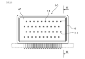
- Example 2 This example is an example of a connector 10 having a connector pin 11 manufactured using the above-described Cu—Fe alloy wire for connector pins. As shown in FIGS. 2 and 3, the connector 10 includes a housing 4 having a recess 41 and a plurality of connector pins 11 disposed through the housing 4. The connector pin 11 is formed from a wire corresponding to the test material 1 in the first embodiment.
- the housing 4 has a substantially rectangular parallelepiped shape as shown in FIGS. 2 and 3, and includes a bottom wall portion 42 through which the connector pin 11 passes, and a side wall portion 43 erected from the outer peripheral edge portion of the bottom wall portion 42. have. A space surrounded by the bottom wall portion 42 and the side wall portion 43 constitutes the recess 41.
- the connector pin 11 has a substantially rod shape as shown in FIGS. 2 and 3, and has a terminal connection portion 111 at one end and a soldering portion 112 at the other end. As shown in FIG. 3, the connector pin 11 of this example is extended toward the bottom wall portion 42 with the terminal connection portion 111 disposed in the recess 41 as a base end. Further, the connector pin 11 penetrates the bottom wall portion 42 and protrudes outward from the housing 4, and 90 ° bending is performed between the bottom wall portion 42 and the soldering portion 112, so that the connector pin 11 is elongated in the longitudinal direction. And bent at right angles. That is, the connector pin 11 of this example is bent so that the terminal connection portion 111 and the soldering portion 112 are perpendicular to each other when the connector pin 11 is disposed in the connector 10.
- the connector pin Cu—Fe based alloy wire 1 can be suitably used as a material for the connector pin 11.
- the connector pin 11 is formed using the wire 1 having a square cross section of 0.64 mm square.
- the cross-sectional shape is deformed into various shapes. It is also possible.
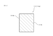
- the cross-sectional shape of the connector pin 11 for example, in a substantially circular, substantially rectangular (see FIG. 4), trapezoidal (see FIG. 5), or quadrangular cross-section, the center portions of the end faces facing each other are recessed inward ( (See FIG. 6).
- a plurality of connector pins 11b are arranged in a row so that the surfaces corresponding to the long sides 114 in the cross section in the wire drawing direction face each other.
- the arrangement space can be saved as compared with the connector pin 11 having a square cross section.
- the entire connector 10 can be reduced in size and weight more easily.
Landscapes
- Chemical & Material Sciences (AREA)
- Engineering & Computer Science (AREA)
- Materials Engineering (AREA)
- Mechanical Engineering (AREA)
- Metallurgy (AREA)
- Organic Chemistry (AREA)
- Conductive Materials (AREA)
- Non-Insulated Conductors (AREA)
Abstract
L'invention concerne un fil en alliage à base de cuivre (Cu) et de fer (Fe) pour des broches de connecteur, ledit fil ayant une composition chimique qui contient une quantité de fer (Fe) égale ou supérieure à 10 % en masse, le reste comprenant du cuivre (Cu) et des impuretés inévitables. fil en alliage à base de cuivre et de fer pour des broches de connecteur présente une structure métallographique où des grains à base de fer qui comprennent du fer comme composant principal et se présentent sous la forme de fibres allongées dans la direction de tréfilage, ont été répartis dans une matrice à base de cuivre qui comprend du cuivre comme composant principal. Les grains à base de fer présentent une moyenne des largeurs qui sont mesurées dans la direction perpendiculaire à la direction de tréfilage, égale ou inférieure à 0,5 μm et présentent une moyenne des longueurs qui sont mesurées dans la direction parallèle à la direction de tréfilage, égale ou supérieure à 4 μm.
Applications Claiming Priority (2)
| Application Number | Priority Date | Filing Date | Title |
|---|---|---|---|
| JP2014-008397 | 2014-01-21 | ||
| JP2014008397A JP2015137372A (ja) | 2014-01-21 | 2014-01-21 | コネクタピン用Cu−Fe系合金線材及びコネクタ |
Publications (1)
| Publication Number | Publication Date |
|---|---|
| WO2015111455A1 true WO2015111455A1 (fr) | 2015-07-30 |
Family
ID=53681263
Family Applications (1)
| Application Number | Title | Priority Date | Filing Date |
|---|---|---|---|
| PCT/JP2015/050564 Ceased WO2015111455A1 (fr) | 2014-01-21 | 2015-01-12 | Fil en alliage à base de cuivre et de fer pour une broche de connecteur et connecteur |
Country Status (2)
| Country | Link |
|---|---|
| JP (1) | JP2015137372A (fr) |
| WO (1) | WO2015111455A1 (fr) |
Cited By (2)
| Publication number | Priority date | Publication date | Assignee | Title |
|---|---|---|---|---|
| WO2016051864A1 (fr) * | 2014-10-01 | 2016-04-07 | 住友電気工業株式会社 | Matériau en alliage de cuivre, borne de connecteur et procédé de fabrication de matériau en alliage de cuivre |
| CN110396619A (zh) * | 2019-08-08 | 2019-11-01 | 宁波金田铜业(集团)股份有限公司 | 一种铜铁合金线材及其制备方法 |
Families Citing this family (3)
| Publication number | Priority date | Publication date | Assignee | Title |
|---|---|---|---|---|
| JP6376168B2 (ja) * | 2016-04-13 | 2018-08-22 | 住友電気工業株式会社 | コネクタ端子用線材およびこれを用いたコネクタ |
| KR102043789B1 (ko) * | 2017-12-26 | 2019-11-12 | 주식회사 포스코 | 철동합금재 및 그 제조방법 |
| KR102274566B1 (ko) * | 2019-06-11 | 2021-07-07 | 고려제강 주식회사 | 균질한 미세조직을 가지는 키니즈 합금 |
Citations (5)
| Publication number | Priority date | Publication date | Assignee | Title |
|---|---|---|---|---|
| JPS63162829A (ja) * | 1986-12-26 | 1988-07-06 | Hisao Wakaumi | 半硬質磁性銅鉄合金 |
| JPH1112698A (ja) * | 1997-04-30 | 1999-01-19 | Hitachi Metals Ltd | 磁気マーカ用バイアス材および磁気マーカならびに磁気マーカ用バイアス材の製造法 |
| JP2000138113A (ja) * | 1998-10-29 | 2000-05-16 | Hitachi Metals Ltd | 半硬質磁性材料および磁気マーカ用バイアス材ならびにその製造法 |
| JP2006206988A (ja) * | 2005-01-31 | 2006-08-10 | Nikko Kinzoku Kk | 電子機器用銅合金 |
| JP2013142178A (ja) * | 2012-01-11 | 2013-07-22 | Sumitomo Electric Ind Ltd | 銅合金 |
-
2014
- 2014-01-21 JP JP2014008397A patent/JP2015137372A/ja active Pending
-
2015
- 2015-01-12 WO PCT/JP2015/050564 patent/WO2015111455A1/fr not_active Ceased
Patent Citations (5)
| Publication number | Priority date | Publication date | Assignee | Title |
|---|---|---|---|---|
| JPS63162829A (ja) * | 1986-12-26 | 1988-07-06 | Hisao Wakaumi | 半硬質磁性銅鉄合金 |
| JPH1112698A (ja) * | 1997-04-30 | 1999-01-19 | Hitachi Metals Ltd | 磁気マーカ用バイアス材および磁気マーカならびに磁気マーカ用バイアス材の製造法 |
| JP2000138113A (ja) * | 1998-10-29 | 2000-05-16 | Hitachi Metals Ltd | 半硬質磁性材料および磁気マーカ用バイアス材ならびにその製造法 |
| JP2006206988A (ja) * | 2005-01-31 | 2006-08-10 | Nikko Kinzoku Kk | 電子機器用銅合金 |
| JP2013142178A (ja) * | 2012-01-11 | 2013-07-22 | Sumitomo Electric Ind Ltd | 銅合金 |
Cited By (2)
| Publication number | Priority date | Publication date | Assignee | Title |
|---|---|---|---|---|
| WO2016051864A1 (fr) * | 2014-10-01 | 2016-04-07 | 住友電気工業株式会社 | Matériau en alliage de cuivre, borne de connecteur et procédé de fabrication de matériau en alliage de cuivre |
| CN110396619A (zh) * | 2019-08-08 | 2019-11-01 | 宁波金田铜业(集团)股份有限公司 | 一种铜铁合金线材及其制备方法 |
Also Published As
| Publication number | Publication date |
|---|---|
| JP2015137372A (ja) | 2015-07-30 |
Similar Documents
| Publication | Publication Date | Title |
|---|---|---|
| JP6126791B2 (ja) | Cu−Ni−Si系銅合金 | |
| JP2008266787A (ja) | 銅合金材およびその製造方法 | |
| WO2015111455A1 (fr) | Fil en alliage à base de cuivre et de fer pour une broche de connecteur et connecteur | |
| JPWO2003076672A1 (ja) | 耐応力緩和特性に優れた高強度高導電性銅合金線材 | |
| JP6162908B2 (ja) | 銅合金板材およびその製造方法 | |
| JP4785092B2 (ja) | 銅合金板材 | |
| WO2013145350A1 (fr) | ALLIAGE À BASE DE Cu-Zn-Sn-Ni-P | |
| TWI521073B (zh) | Copper alloy plate, and with its high current with electronic components and thermal electronic components | |
| JP6050588B2 (ja) | 銅合金線 | |
| JP6328380B2 (ja) | 導電性及び曲げたわみ係数に優れる銅合金板 | |
| WO2016051864A1 (fr) | Matériau en alliage de cuivre, borne de connecteur et procédé de fabrication de matériau en alliage de cuivre | |
| JP2018159104A (ja) | 強度及び導電性に優れる銅合金板 | |
| JP6835636B2 (ja) | 強度及び導電性に優れる銅合金板 | |
| KR102915759B1 (ko) | Cu-Ag계 합금선 | |
| JP2014173167A (ja) | Cu−Ni−Si系銅合金 | |
| JP2017160513A (ja) | 銅合金板材およびその製造方法 | |
| JP5449595B1 (ja) | 導電性及び曲げたわみ係数に優れる銅合金板 | |
| JP5761400B1 (ja) | コネクタピン用線材、その製造方法及びコネクタ | |
| JP2015048519A (ja) | 導電性及び曲げたわみ係数に優れる銅合金板 | |
| JP4254815B2 (ja) | 端子・コネクタ用銅合金材 | |
| JP2016204757A (ja) | Cu−Ni−Si系銅合金 | |
| JP2018156804A (ja) | プレスフィット端子および基板用コネクタ | |
| CN114867876B (zh) | 连接端子 | |
| JP2015117392A (ja) | 端子金具用Cu−Fe系合金圧延板及び端子金具 | |
| JP2010209379A (ja) | 端子・コネクタ用銅合金材及びその製造方法 |
Legal Events
| Date | Code | Title | Description |
|---|---|---|---|
| 121 | Ep: the epo has been informed by wipo that ep was designated in this application |
Ref document number: 15740786 Country of ref document: EP Kind code of ref document: A1 |
|
| NENP | Non-entry into the national phase |
Ref country code: DE |
|
| 122 | Ep: pct application non-entry in european phase |
Ref document number: 15740786 Country of ref document: EP Kind code of ref document: A1 |