WO2015111473A1 - 太陽光発電装置の出力推定方法および装置並びにこれを用いた電力系統監視装置 - Google Patents
太陽光発電装置の出力推定方法および装置並びにこれを用いた電力系統監視装置 Download PDFInfo
- Publication number
- WO2015111473A1 WO2015111473A1 PCT/JP2015/050727 JP2015050727W WO2015111473A1 WO 2015111473 A1 WO2015111473 A1 WO 2015111473A1 JP 2015050727 W JP2015050727 W JP 2015050727W WO 2015111473 A1 WO2015111473 A1 WO 2015111473A1
- Authority
- WO
- WIPO (PCT)
- Prior art keywords
- power generation
- estimation
- solar radiation
- output
- solar
- Prior art date
- Legal status (The legal status is an assumption and is not a legal conclusion. Google has not performed a legal analysis and makes no representation as to the accuracy of the status listed.)
- Ceased
Links
Images


Classifications
-
- H—ELECTRICITY
- H02—GENERATION; CONVERSION OR DISTRIBUTION OF ELECTRIC POWER
- H02S—GENERATION OF ELECTRIC POWER BY CONVERSION OF INFRARED RADIATION, VISIBLE LIGHT OR ULTRAVIOLET LIGHT, e.g. USING PHOTOVOLTAIC [PV] MODULES
- H02S50/00—Monitoring or testing of PV systems, e.g. load balancing or fault identification
-
- H—ELECTRICITY
- H02—GENERATION; CONVERSION OR DISTRIBUTION OF ELECTRIC POWER
- H02J—ELECTRIC POWER NETWORKS; CIRCUIT ARRANGEMENTS OR SYSTEMS FOR SUPPLYING OR DISTRIBUTING ELECTRIC POWER; SYSTEMS FOR STORING ELECTRIC ENERGY
- H02J3/00—Circuit arrangements for AC mains or AC distribution networks
- H02J3/38—Arrangements for feeding a single network from two or more generators or sources in parallel; Arrangements for feeding already energised networks from additional generators or sources in parallel
- H02J3/381—Dispersed generators
-
- H—ELECTRICITY
- H02—GENERATION; CONVERSION OR DISTRIBUTION OF ELECTRIC POWER
- H02J—ELECTRIC POWER NETWORKS; CIRCUIT ARRANGEMENTS OR SYSTEMS FOR SUPPLYING OR DISTRIBUTING ELECTRIC POWER; SYSTEMS FOR STORING ELECTRIC ENERGY
- H02J2101/00—Supply or distribution of decentralised, dispersed or local electric power generation
- H02J2101/20—Dispersed power generation using renewable energy sources
- H02J2101/22—Solar energy
- H02J2101/24—Photovoltaics
-
- Y—GENERAL TAGGING OF NEW TECHNOLOGICAL DEVELOPMENTS; GENERAL TAGGING OF CROSS-SECTIONAL TECHNOLOGIES SPANNING OVER SEVERAL SECTIONS OF THE IPC; TECHNICAL SUBJECTS COVERED BY FORMER USPC CROSS-REFERENCE ART COLLECTIONS [XRACs] AND DIGESTS
- Y02—TECHNOLOGIES OR APPLICATIONS FOR MITIGATION OR ADAPTATION AGAINST CLIMATE CHANGE
- Y02E—REDUCTION OF GREENHOUSE GAS [GHG] EMISSIONS, RELATED TO ENERGY GENERATION, TRANSMISSION OR DISTRIBUTION
- Y02E10/00—Energy generation through renewable energy sources
- Y02E10/50—Photovoltaic [PV] energy
- Y02E10/56—Power conversion systems, e.g. maximum power point trackers
Definitions
- the present invention relates to a method and apparatus for estimating the output of a solar power generation apparatus connected to an electric power system, and an electric power system monitoring apparatus using the same, and in particular, it is possible to The present invention relates to a method and apparatus for estimating the output of a solar power generation apparatus and an electric power system monitoring apparatus using the same, by performing estimation of the amount of solar radiation with a plurality of methods to calculate the output estimation and estimation error of the solar power generation apparatus.
- the power system is controlled to keep the power demand equal to the power generation at all times, and to maintain the voltage of each part of the system within a specified voltage range.
- tap switching of a transformer load ratio tap switching transformer LRT: Load Ratio Control Transformer
- LRT Load Ratio Control Transformer
- SVR Step Voltage Regulator
- These voltage regulators are generally set to operate with a response time constant of several tens of seconds before tap switching.
- the voltage regulator installed at the end of the distribution line (feeder) is more than the voltage regulator installed at the substation side (outgoing side) It is also common to set the response time constant later. This reduces unnecessary operation of the terminal voltage regulator.
- the power generation output of the solar power generation apparatus PV is affected by the weather fluctuation, which causes the rapid voltage fluctuation of the distribution system.
- the response time constant of a voltage regulator equipped with a mechanical mechanism such as a tap is usually slower than the phenomenon of voltage fluctuation due to rapidly changing power, such as load or photovoltaic power output. Therefore, if possible, it is desirable to determine the current control amount and control target value in consideration of the predicted output change of the solar power generation device PV. For that purpose, it is necessary to perform tap control appropriately according to the amount of power generation of the solar power generation device PV.
- Non-Patent Document 1 shows a method capable of accurately estimating the solar power generation device PV output at an arbitrary point using information on the output measurement point of the rare solar power generation device PV.
- Patent Document 1 shows a method of predicting using not only the past power generation amount of the self-photovoltaic power generation device PV but also the power generation amounts of other solar power generation devices PV.
- Patent Document 2 shows a method of predicting the power generation amount of the solar power generation device PV based on the data having similarity by comparing the power generation time-series data of the other solar power generation device PV and the fluctuation pattern. ing.
- Non-Patent Document 1 Although an error is included in the output grasp of the solar power generation device PV, a method for grasping the magnitude of the error is not shown. Therefore, there exists a subject which can not perform system control (supply-and-demand control, voltage control) which considered the risk by power generation amount estimation error.
- the present invention it is possible to estimate the amount of solar radiation installed at a point different from the solar radiation measurement point and to grasp the estimation error amount from the solar radiation measurement value of a particularly limited point, thereby obtaining the output of the solar power generation device An estimation method and apparatus, and a power system monitoring apparatus using the same.
- the present invention is a solar power generation output estimation method for estimating the output of a solar power generation device based on a measured value of solar radiation, and the actinometer installation point information and the measured value of the solar radiation meter and the solar power generation device installation
- the photovoltaic power generation output estimation method and estimation device of the present invention can (1) reduce the number of measuring devices required for PV power generation device output estimation / prediction, (2) safety side design considering errors of estimation / prediction values , Control is possible, and (3) there are effects such as being able to reduce the interconnection countermeasure cost when introducing a plurality of solar power generation apparatuses.
- the figure which shows the process function structure of a solar power generation device output estimation apparatus The figure which shows an example of the distribution system by which the solar power generation device and the solar radiation meter were installed.
- the figure which shows the structural example of a solar power generation device output estimation apparatus The figure which shows the processing flow which converts a solar radiation estimated value into a solar power generation device electric power generation output value.
- the figure which shows the view of a linear complementation system as an example of the solar radiation amount estimation method.
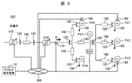
- FIG. 2 is the figure which showed an example of the distribution system 100 (feeder) in which the solar power generation device PV and the solar radiation meter 180 were installed.
- a typical distribution system 100 shown in this figure includes a node (bus) 120 and a distribution line 140 connecting them, a load 150 connected to the node 120, a solar power generation device PV, and a sensor 170 installed on the distribution line.
- the output of the pyranometer 180 is connected to the solar power generation device output estimation device 10 via the communication network 300 to transmit measurement values one after another.
- a pyranometer is not necessarily installed in the same place as a solar power generation device.
- the actinometer 180 may be installed in the vicinity of the solar power generation device installation point in the distribution system 100, or may be installed in a completely different place such as a substation. ing.
- the eclipse meter 180 even if the eclipse meter 180 is installed, it may not be connected to the solar power generation device output estimation apparatus 10 via the communication network 300.
- the output itself of the solar power generation device PV may be transmitted to the solar power generation device output estimation device 10 instead of the solar radiation meter instead of the solar radiation meter.
- the sensor 170, the distribution substation 110, the automatic voltage regulator SVR, and the static reactive power compensator SVC are configured to enable information transmission with the photovoltaic power output estimation device 10 via the communication network 300. It is done.
- the estimated output value of the solar power generation device PV in the feeder and the estimated error amount are calculated based on the measurement data of the solar radiation meter 180. If the output estimated value and the estimated error amount of the photovoltaic power generation system PV in the feeder are known, the following effects on distribution system management can be obtained by reflecting this result on the power system monitoring device.
- the ratio of the output of the solar power generation apparatus PV included in the active power and reactive power detected by the sensor 170 can be grasped. As a result, it is possible to predict the amount of power flow when the output of the solar power generation device PV rapidly and sharply decreases, and it is possible to monitor as needed whether supply and demand control and voltage control are possible.
- the distribution substation 110, the automatic voltage regulator SVR, and the static reactive power compensator SVC adjust the present control amount, control response speed, and the like in case of possible output change of the photovoltaic power generation device PV. Adjustment or the like produces an effect that enables more efficient control.
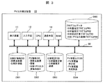
- FIG. 3 is a diagram showing a configuration example of a photovoltaic power generation system output estimation device 10 according to an embodiment of the present invention.
- the output estimation device 10 is configured by a computer system, and a display device 11, an input unit 12 such as a keyboard or a mouse, a computer CPU, a communication unit 14, a random access memory RAM, and various databases are connected to a bus line 30.
- a database DB of the computer system a solar radiation information database DB1, a solar power generation device information database DB2, a solar radiation estimation database DB3, a solar power generation output database DB4, and a program database DB5 are provided.
- the computer CPU executes a calculation program to instruct image data to be displayed, search data in various databases, and the like.
- the random access memory RAM includes solar radiation meter installation point coordinates and solar radiation measurement value data, solar power generation equipment installation point coordinates, rated capacity, solar radiation-photovoltaic power conversion coefficient data, solar radiation estimated value and solar radiation estimation error calculation result data, It is a memory for temporarily storing calculation result data such as a photovoltaic power generation device power generation amount estimation value and estimation error calculation result data. Based on these data, the computer CPU generates necessary image data and displays it on the display device 11 (for example, a display screen).
- the display device 11 for example, a display screen
- the pyranometer information database DB1 stores pyranometer installation point coordinates indicating geographical coordinates at which the eclipse meter 180 is installed, and time-series sunshine measurement value data measured by the pyranometer. Therefore, in the case of the distribution system configuration of FIG. 2, the amount of solar radiation in the vicinity of the solar power generation devices PV1, PV3, and PV6 is stored as time information for each geographical coordinate.
- the solar power generation device information database DB2 includes solar power generation device installation point coordinates indicating geographical coordinates at which the solar power generation device PV is installed, a rated capacity of each solar power generation device, and a solar radiation amount.
- solar radiation-photovoltaic power generation conversion factor data which is a factor for converting into a device output amount. According to this, for example, from the amount of solar radiation measured in the vicinity of the solar power generation device PV1, the power generation amount of the solar power generation device PV1 can be estimated according to the rated capacity of the solar power generation device PV1.
- the solar radiation amount estimated value calculated by the program and the solar radiation amount estimation error calculation result data are stored.
- the solar power generation device power generation output database DB 4 stores data such as a solar power generation device estimated power generation value calculated by the program and estimated error calculation result data.
- the program database DB5 stores a plurality of types of solar radiation amount estimation programs PR1 and PR2, a solar radiation error calculation program PR3 and a solar radiation-photovoltaic power generation output conversion program PR4 which are calculation programs. These programs are read by the computer CPU as needed, and calculations are performed.
- the processing function structure of the solar power generation device output estimation apparatus 10 of this invention is demonstrated using FIG.
- the solar power generation apparatus output estimation device 10 includes a solar radiation amount measurement unit 31, a plurality of solar radiation amount estimation processing units 32, 33, a solar radiation estimation error amount calculation unit 34, an elapsed time measurement unit 35, a solar radiation restart processing unit 36, solar radiation- Each function of the solar power generation device output conversion unit 37, solar radiation power generation device information data DB2 which is the above four databases, solar power generation device information data DB2, solar radiation power estimation data DB3, and solar power generation device power generation output data DB4 Ru.
- the solar radiation amount measurement unit 31 corresponds to an input part in which measurement data of the solar radiation meter 180 is taken into the solar power generation device output estimation device 10 via the communication network 300.
- it may be regarded as a function of taking out solar radiation measurement value data stored in the actinometer information database DB1.
- the solar radiation amount estimation processing units 32 and 33 are processing functions for executing a plurality of different types of solar radiation amount estimation programs PR1 and PR2 according to different methods among the calculation programs stored in the program database DB5. For example, the solar radiation amount estimation processing unit 32 executes the solar radiation amount estimation program PR1, and using the same data, the solar radiation amount estimation processing unit 33 executes the solar radiation amount estimation program PR2 to estimate the solar radiation amount.
- the solar radiation amount estimation processing units 32, 33 obtain the solar radiation measurement value from the solar radiation amount measurement unit 31, obtain the solar radiation meter installation point coordinates from the solar radiation information database DB1, and the solar power generation device from the solar power generation device information database DB2. Receive the coordinates of the installation point, the rated capacity of each solar power generation device, and the solar radiation-solar power generation conversion coefficient, and calculate the solar radiation amount of each solar power generation device point.
- the solar radiation amount estimation processing units 32 and 33 estimate the solar radiation amount by different methods.
- the calculation method of the different system in the solar radiation amount estimation process parts 32 and 33 is later mentioned using FIG.5, FIG.6, FIG.7.
- the solar radiation estimation error amount calculation unit 34 is a processing function of executing the solar radiation error calculation program PR3 among the calculation programs stored in the program database DB5.
- the solar radiation amount estimation processing units 32 and 33 the solar radiation amount calculation result obtained by the different calculation method of the solar power generation device installation point is received, and the solar radiation estimation error amount is calculated from the difference.
- the elapsed time measurement unit 35 measures the elapsed time from the time when the previous solar radiation amount and solar radiation estimation error amount were calculated, and the measurement result is used as the solar radiation estimation error amount calculation unit Pass to 34
- the solar radiation estimation error amount measured by the solar radiation estimation error amount calculation unit 34 and the solar radiation estimation amount calculated by the solar radiation amount estimation processing units 32 and 33 are stored in the solar radiation estimation database DB 3 and solar radiation-photovoltaic power generation output conversion It is passed to section 37.
- the solar radiation-photovoltaic power generation output conversion unit 37 is a processing function that executes the solar radiation-photovoltaic power generation output conversion program PR4 among the calculation programs stored in the program database DB5.
- the amount of solar radiation is converted into the amount of output of each solar power generation device according to the rated capacity of the solar power generation device or the solar radiation-solar power generation conversion coefficient, and stored in the solar power generation device power generation output database DB4.
- the solar radiation restart processing unit 36 starts reimplementation of the solar power generation device output estimation processing with the elapse of a predetermined time. That is, a trigger signal for performing an operation at fixed time intervals is given.
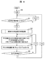
- FIG. 1 The process flow which shows an example of the solar power generation device output estimation method which converts a solar radiation estimated value into a solar power generation device electric power generation output value is demonstrated using FIG.
- processing flow first, at processing step S0, the value of time t measured by the above-mentioned elapsed time measuring unit 35 is initialized to zero.
- the processing step S1 is a block corresponding to the processing content of the solar radiation restart processing unit 36, where the amount of solar radiation when the value of the time t measured by the above-mentioned elapsed time measuring unit 35 exceeds the fixed time tmax Start estimation. This enables continuous estimation operation at fixed time intervals.
- processing step S2 a plurality of solar radiation amount estimation processes are performed by different calculation methods. This corresponds to executing the processes of the plurality of solar radiation amount estimation processing units 32 and 33 respectively. Note that different calculation methods in the solar radiation amount estimation processing units 32 and 33 and a specific method of determining the solar radiation device solar radiation amount estimated value and the estimation error will be described later with reference to FIGS. 5, 6, and 7.
- a plurality of solar radiation amount estimation processing calculation results are read. Specifically, the solar radiation amount estimated value Si (kWh / m 2 ) of the solar power generation device installation point i, the solar power generation device rated capacity Ppv0i (kW), and the solar radiation-photovoltaic power generation output conversion coefficient Ki are read.
- the installation point i of a solar power generation device and a pyranometer should just be in a close relationship here, and does not mean the same point in a strict sense.
- the process of the solar power generation apparatus output estimation device 10 has been described above, it is also possible to similarly obtain the solar power generation apparatus solar radiation amount change estimated value and the estimation error instead of the solar power generation apparatus solar radiation estimated value and the estimation error. It is possible. As shown in FIG. 9, it is possible to obtain the solar power generation apparatus solar radiation amount variation estimated value and the estimation error by calculating the output variation ⁇ Ppv generated during a certain time interval ⁇ t as in the above-mentioned process. It is.
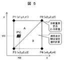
- FIG. 5 is a conceptual diagram showing the concept of a linear interpolation method as an example of a solar radiation amount estimation method.
- This estimation method is a method of calculating the solar radiation of the solar power generation system installation point by distance division taking into consideration the geographical arrangement from the solar radiation measurement values of the three solar radiation measurement points in the vicinity of the solar power generation system installation point.
- the x-axis and the y-axis represent geographical coordinates, and the solar power generator output corresponding to each coordinate is indicated as the z-axis.
- it is considered to estimate the solar radiation amount PVj at the j point (coordinates (xpj, ypj)) which is the installation point of the solar power generation device in the figure.
- the solar radiation amount measurement is performed at a plurality of points in the vicinity of the j point, and has already been obtained together with the geographical information.
- the solar radiation amounts of four points P1, P2, P3, and P4 and geographical information are obtained.
- the photovoltaic power generation apparatus output between the measurement points is three points (P1 (x1, y1, z1), P2 (x2, y2, z2), P3 (x3, y3, z3) which are arbitrarily set in the vicinity.
- the solar generator output z at point j is expressed by the following equation (2).
- a, b and c are uniquely determined by solving simultaneous equations.
- FIG. 6 is a processing flow diagram of the linear interpolation method.
- actinometer setting point coordinates actinometer setting point coordinates
- solar power generation device setting point coordinates solar radiation amount measured value Si (kWh / m 2 ) are read.
- the solar radiation amount z j of the solar power generation device installation point j is calculated. The calculation of z j may be performed by equation (4).
- FIG. 7 is a conceptual view showing the concept of a representative value method which is another example of the solar radiation amount estimation method.
- a specific actinometer is representative, and the amount of solar radiation at the neighboring solar power generation device points is considered to be equal to the representative solar radiation measurement value.
- the measurement point closest to the installation point of the solar power generation device is selected.
- One of the methods is the Voronoi diagram (Voronoi division). This is a diagram in which a plurality of points (base points) arranged at arbitrary positions in a certain metric space are divided into regions according to which generatically other points are close to other points in the same metric space. It is. In particular, in the case of a two-dimensional Euclidean plane, the boundary of the region is part of the bisector of each generating point.
- Voronoi division boundaries are determined so that distances are equal. At this time, a set of points located at the same distance from the mother point is represented by a circle. Thus, it is possible to estimate the amount of solar radiation at each solar power generation device installation point.
- FIG. 8 shows an example of calculation of the solar radiation amount estimated value and the estimated error amount.
- the example which estimated the solar radiation amount of a certain solar power generation device installation point by two estimation methods of the above-mentioned linear complementation system and a representative value system is shown.
- the thick solid linear interpolation method and the thick dotted representative value method calculate results with different amounts of solar radiation at each time due to differences in estimation algorithms. These differences (fine dotted lines) are shown as solar radiation amount estimation errors.
- an output estimated value and an output estimation error value are given to an electric power system monitoring apparatus that implements supply and demand control and voltage control, so that the output of the solar power generation device PV included in the active power and reactive power detected by the sensor 170 It becomes possible to grasp the ratio of As a result, it is possible to predict the amount of power flow when the output of the photovoltaic power generation system PV sharply and rapidly decreases, and it is possible to monitor whether demand and supply control and voltage control are possible or to control as needed. It occurs.
- the power system monitoring device performs monitoring and control using the distribution substation 110, the automatic voltage regulator SVR, and the static reactive power compensation device SVC, the output change of the solar power generation device PV that may occur By adjusting the current control amount and adjusting the control response speed, the effect of enabling more efficient monitoring and control is produced.
- the amount of power generation of the solar power generation device can be grasped, whereby the load amount can be grasped from the measurement value of the sensor of the line. Also, by considering the error, it is possible to grasp the estimation error amount of the load amount, which makes it possible to appropriately carry out overload prevention and load interchange taking into consideration sudden dropout of the photovoltaic device. effective.
- the sudden PV power output fluctuation range increases from the current value to the maximum capacity of the PV power equipment at most or decreases to 0. It can be estimated that this makes it possible to minimize instantaneous reserve capacity and voltage control margin with respect to the solar power generator output change. As a result, it is possible to suppress a decrease in the generator efficiency and reduce the capacity of the voltage adjustment facility, and it is possible to reduce the system operation and facility costs.
- the procedure of obtaining the amount of solar radiation and its error amount by different method and converting it into the estimated energy after that is taken, the amount of solar radiation is calculated by the different method and then converted into the estimated energy Then, a procedure may be taken to calculate an error of the estimated power amount as a difference between the estimated power amounts.
- the new idea that the difference between the estimated powers by different method operation corresponds to the amount of output error in contrast to the problem that the amount of error included in the detected amount of photovoltaic power generation can not be estimated, the new idea that the difference between the estimated powers by different method operation corresponds to the amount of output error.
- the device is configured, the method is devised, and it can be applied to the subsequent control.
- It can be utilized as a photovoltaic power generation system output of power system and estimation error grasping device, and a photovoltaic power generation system output change amount estimation device.
- a photovoltaic power generation system output of power system and estimation error grasping device By utilizing it for determining the spinning reserve capacity of the supply and demand adjustment device of the electric power system, it can be used as a function of a frequency adjustment device, an economic load distribution device, and the like.
- it can be used as a function of voltage regulator, load interchange determination device of distribution system, and distribution automation system.
- the distribution system it can be used as a voltage maintenance measure and a distribution facility improvement measure improvement measure corresponding to the addition of distributed power sources such as solar power generation.
Landscapes
- Engineering & Computer Science (AREA)
- Power Engineering (AREA)
- Supply And Distribution Of Alternating Current (AREA)
- Remote Monitoring And Control Of Power-Distribution Networks (AREA)
Abstract
限られた地点の日射測定値から、日射測定地点と異なる地点に設置された日射量の推定および推定誤差量の把握を行うことで、太陽光発電装置の出力を推定する。日射計測値を元に太陽光発電装置の出力を推定する太陽光発電出力推定方法であって、日射計設置点情報と日射計計測値および太陽光発電装置設置点情報から、太陽光発電装置設置点における日射量を推定する第1の推定手法と、第1の推定手法と異なる手法で太陽光発電装置設置点における日射量を推定する第2の推定手法と、推定された日射量と当該太陽光発電装置の定格容量から太陽光発電装置の出力を推定する出力推定手法と、第1と第2の推定手法の差から太陽光発電装置出力の推定誤差を求める誤差推定手法を備える。
Description
本発明は、電力系統に接続される太陽光発電装置の出力推定方法および装置並びにこれを用いた電力系統監視装置に係り、特に限られた地点の日射測定値から、日射測定地点と異なる地点の日射量推定を複数の方法で行うことで、太陽光発電装置の出力推定および推定誤差を計算する、太陽光発電装置の出力推定方法および装置並びにこれを用いた電力系統監視装置に関する。
電力系統は、電力需要と発電を常に等しくするとともに、系統各地の電圧を規定電圧範囲に維持するように制御されている。例えば、配電系統の電圧の制御を一例としてあげると、配電用変電所に設置された変圧器(負荷時タップ切替変圧器LRT:Load Ratio Control Transformer)のタップ切替や、配電線上に設置された自動電圧調整器(SVR:Step Voltage Regulator)などのタップ切替によって制御されている。
これらの電圧調整装置(負荷時タップ切替変圧器LRTや自動電圧調整器SVR)は、タップの切替までに一般的に数十秒の応答時定数で動作するように設定されている。また複数の電圧調整装置が配電線路に直列に設置される場合、配電線路(フィーダ)の末端側に設置される電圧調整装置は、変電所側(送出し側)に設置される電圧調整装置よりも応答時定数を遅く設定するのが一般的である。これにより、末端側の電圧調整装置の不要な動作を少なくしている。
ところで、近年の配電系統では太陽光発電装置PVを備えた需要家が増大している。この場合に、太陽光発電装置PVの発電出力は天候変動に左右され配電系統の急激な電圧変動を生じさせる原因となっている。
然るに、タップなどの機械機構を備える電圧調整装置の応答時定数は、負荷や太陽光発電出力など、早く変化する電力に起因する電圧変動の現象に比べて遅いのが通常である。
従って可能であれば、予想される太陽光発電装置PVの出力変化を考慮して、現在の制御量や制御目標値を決定することが望ましい。そのためには、太陽光発電装置PVの発電量に応じて、タップ制御を適切に行う必要がある。
従って可能であれば、予想される太陽光発電装置PVの出力変化を考慮して、現在の制御量や制御目標値を決定することが望ましい。そのためには、太陽光発電装置PVの発電量に応じて、タップ制御を適切に行う必要がある。
このような課題に対し、配電系統においては、変電所バンク、フィーダ、開閉器区間単位内で発生する太陽光発電装置PVの発電出力量を正しく推定し、出力変化量を予測することが重要となる。
太陽光発電装置PVによる発電の出力把握および予測方法として、次のような手法が知られている。例えば、非特許文献1には、稀少な太陽光発電装置PVの出力計測点の情報を用いて任意地点の太陽光発電装置PV出力を精度良く推定できる手法が示されている。
また、特許文献1には、自己太陽光発電装置PVの過去の発電量のみならず、他の太陽光発電装置PVの発電量も用いて予測する手法が示されている。
また、特許文献2には、他の太陽光発電装置PVの発電時系列データと変動パターンを比較して、類似度するデータに基づいて太陽光発電装置PVの発電量を予測する方法が示されている。
「配電系統内の太陽光発電出力推定に関する研究」、平成25年電気学会全国大会、6-111(2013年)
前述の非特許文献1に記載の方法では、太陽光発電装置PVの出力把握に誤差が含まれるが、誤差の大きさを把握する手法が示されていない。そのため、発電量推定誤差によるリスクを考慮した系統制御(需給制御、電圧制御)を行うことができない課題がある。
また、特許文献1に記載の方法では、ここで使用するモデル式(モデル式の係数)が比較的硬直的であり時々刻々と変わる発電環境に対応して変更することが困難である、また風向き変化による雲の移動等に対応した発電量の予測が困難であり、近い将来の発電量の予測が困難となるなどの課題がある。
また、特許文献2に記載の方法では、推定誤差の大きさや、推定誤差リスクの時間経過による変化の影響が考慮されていないといった課題がある。
以上のことから本発明は、特に限られた地点の日射測定値から、日射測定地点と異なる地点に設置された日射量の推定および推定誤差量の把握を行うことで、太陽光発電装置の出力推定方法および装置並びにこれを用いた電力系統監視装置を提供するものである。
以上のことから本発明においては、日射計測値を元に太陽光発電装置の出力を推定する太陽光発電出力推定方法であって、日射計設置点情報と日射計計測値および太陽光発電装置設置点情報から、太陽光発電装置設置点における日射量を推定する第1の推定手法と、第1の推定手法と異なる手法で太陽光発電装置設置点における日射量を推定する第2の推定手法と、推定された日射量と当該太陽光発電装置の定格容量から太陽光発電装置の出力を推定する出力推定手法と、第1と第2の推定手法の差から太陽光発電装置出力の推定誤差を求める誤差推定手法を備えることを特徴とする。
本発明の太陽光発電出力推定方法および推定装置により、(1)太陽光発電装置出力推定・予測に必要な計測装置を少なくできる、(2)推定・予測値の誤差を考慮した安全側の設計、制御が可能、(3)複数太陽光発電装置導入時の連系対策コストを低減できる、等の効果がある。
また、本発明のそれ以外の効果については、明細書中で説明する。
以下、本発明の実施例について図面を用いて説明する。
図2は、太陽光発電装置PVや日射計180が設置された配電系統100(フィーダ)の一例を示した図である。この図で示される典型的な配電系統100は、ノード(母線)120およびそれらを接続する配電線路140、ノード120に接続される負荷150や太陽光発電装置PV、配電線路に設置されるセンサ170、日射計180、配電用変電所110、静止形無効電力補償装置SVC(Static Var Compensator)、電圧調整装置(図2の例では自動電圧調整器SVR)などで構成される。
ここで、日射計180の出力は、通信ネットワーク300を介して、太陽光発電装置出力推定装置10に接続され、逐次計測値を伝送する。なお日射計は、太陽光発電装置と同じ場所に設置されるとは限らない。日射計180は、配電系統100内の太陽光発電装置設置点の近傍に設置されることもあれば、変電所など全く別の場所に設置されることもあり、配電系統100内に適宜配置されている。また日射計180が設置されていても、通信ネットワーク300を介して、太陽光発電装置出力推定装置10に接続されていないこともある。
図の例では、太陽光発電装置PV1、PV3、PV6の近傍には設置されているが、太陽光発電装置PV2、PV4、PV5の近傍には設置されていない場合で説明する。なお、日射計の代わりに太陽光発電装置PVの出力そのものを日射計の代わりに太陽光発電装置出力推定装置10に伝送する構成としてもよい。
また、センサ170、配電用変電所110、自動電圧調整器SVR、静止形無効電力補償装置SVCは、通信ネットワーク300を介して太陽光発電装置出力推定装置10と情報伝送を可能とするように構成されている。
太陽光発電装置出力推定装置10では、日射計180の計測データを元に、フィーダ内の太陽光発電装置PVの出力推定値および推定誤差量を演算する。フィーダ内の太陽光発電装置PVの出力推定値および推定誤差量が判明すると、この結果を電力系統監視装置に反映させることで、次のような配電系統管理上の効果が得られる。
まずセンサ170が検知する有効電力、無効電力に含まれる太陽光発電装置PVの出力の割合が把握可能となる。これにより、太陽光発電装置PVの出力が急増、急減した場合の潮流量を予測することが可能となり、需給制御や電圧制御が可能か、随時監視することができる効果を生じる。
また、配電用変電所110、自動電圧調整器SVR、静止形無効電力補償装置SVCは、起こりうる太陽光発電装置PVの出力変化に備えて、現在の制御量を調整したり、制御応答速度を調整したりすることで、より効率的な制御が可能となる効果を生じる。
図3は、本発明の一実施例による太陽光発電装置出力推定装置10の構成例を示す図である。出力推定装置10は計算機システムで構成されており、表示装置11、キーボードやマウス等の入力手段12、コンピュータCPU、通信手段14、ランダムアクセスメモリRAM、および各種データベースがバス線30に接続されている。また計算機システムのデータベースDBとして、日射計情報データベースDB1、太陽光発電装置情報データベースDB2、日射推定データベースDB3、太陽光発電装置発電出力データベースDB4、およびプログラムデータベースDB5を備える。
ここでコンピュータCPUは、計算プログラムを実行して表示すべき画像データの指示や、各種データベース内のデータの検索等を行う。ランダムアクセスメモリRAMは、日射計設置点座標および日射計測値データ、太陽光発電装置設置点座標や定格容量や日射-太陽光発電変換係数データ、日射量推定値および日射量推定誤差計算結果データ、太陽光発電装置発電量推定値および推定誤差計算結果データ等の計算結果データを一旦格納するメモリである。これらのデータに基き、コンピュータCPUによって必要な画像データを生成して、表示装置11(例えば表示ディスプレイ画面)に表示する。
太陽光発電装置出力推定装置10内には、大きく分けて5つのデータベースDBが搭載されている。日射計情報データベースDB1には、日射計180が設置されている地理的座標を示す日射計設置点座標、日射計によって測定された時系列的な日射計測値データが記憶されている。従って、図2の配電系統構成の場合、太陽光発電装置PV1、PV3、PV6の近傍の日射量が地理的座標ごとの時間情報として記憶されていることになる。
太陽光発電装置情報データベースDB2には、太陽光発電装置PVが設置されている地理的座標を示す太陽光発電装置設置点座標や、各太陽光発電装置の定格容量や、日射量を太陽光発電装置出力量に変換するための係数である日射-太陽光発電変換係数データが格納されている。これによれば、例えば太陽光発電装置PV1の近傍で計測した日射量から、太陽光発電装置PV1の定格容量に見合って、太陽光発電装置PV1の発電量を推定することができる。
日射推定データベースDB3には、プログラムによって計算された日射量推定値および日射量推定誤差計算結果データが格納されている。
太陽光発電装置発電出力データベースDB4には、プログラムによって計算された太陽光発電装置発電量推定値および推定誤差計算結果データ等のデータが格納されている。
プログラムデータベースDB5には、計算プログラムである複数種類の日射量推定プログラムPR1、PR2、日射誤差計算プログラムPR3、日射-太陽光発電出力変換プログラムPR4を格納する。これらのプログラムは、必要に応じてコンピュータCPUに読み出され、計算が実行される。
図1を用いて、本発明の太陽光発電装置出力推定装置10の処理機能構成について説明する。太陽光発電装置出力推定装置10は、日射量計測部31、複数の日射量推定処理部32、33、日射推定誤差量算出部34、経過時間計測部35、日射再起動処理部36、日射-太陽光発電装置出力変換部37の各機能と、前述の4つのデータベースである日射計情報データベースDB1、太陽光発電装置情報データDB2、日射推定データDB3、太陽光発電装置発電出力データDB4で構成される。
図1において、まず日射量計測部31は、日射計180の計測データが通信ネットワーク300を介して太陽光発電装置出力推定装置10に取り込まれる入力部分に相当する。
あるいは日射計情報データベースDB1に記憶された日射計測値データの取り出し機能ととらえてもよい。
あるいは日射計情報データベースDB1に記憶された日射計測値データの取り出し機能ととらえてもよい。
日射量推定処理部32、33は、プログラムデータベースDB5に格納された計算プログラムのうち、異方式による複数種類の日射量推定プログラムPR1、PR2を実行する処理機能である。例えば日射量推定処理部32は、日射量推定プログラムPR1を実行し、また同じデータを用いて日射量推定処理部33は日射量推定プログラムPR2を実行して日射量を推定する。
日射量推定処理部32、33では、日射量計測部31から日射計測値を入手し、日射計情報データベースDB1から日射計設置点座標を入手し、太陽光発電装置情報データベースDB2から太陽光発電装置設置点座標、各太陽光発電装置の定格容量、日射-太陽光発電変換係数を受け取り、各太陽光発電装置地点の日射量を計算する。ここで、日射量推定処理部32、33は各々異なる方法によって日射量の推定を行っている。なお日射量推定処理部32、33における異方式の演算手法については図5、図6、図7を用いて後述する。
日射推定誤差量算出部34は、プログラムデータベースDB5に格納された計算プログラムのうち、日射誤差計算プログラムPR3を実行する処理機能である。ここでは、日射量推定処理部32、33から太陽光発電装置設置地点の異方式の演算手法で求めた日射量計算結果を受け取り、その差分から日射推定誤差量を計算する。日射推定誤差量算出部34での処理のために、経過時間計測部35は、前回日射量および日射推定誤差量を計算した時間からの経過時間を測定し、測定結果を日射推定誤差量算出部34に渡す。
日射推定誤差量算出部34によって計測された日射推定誤差量および日射量推定処理部32、33で計算された日射推定量は、日射推定データベースDB3に格納されるとともに、日射-太陽光発電出力変換部37に渡される。
日射-太陽光発電出力変換部37は、プログラムデータベースDB5に格納された計算プログラムのうち、日射-太陽光発電出力変換プログラムPR4を実行する処理機能である。太陽光発電装置の定格容量や日射-太陽光発電変換係数によって、日射量を各太陽光発電装置出力量に変換し、太陽光発電装置発電出力データベースDB4に格納する。
日射再起動処理部36では、前回の太陽光発電装置出力推定処理後、一定時間の経過をもって太陽光発電装置出力推定処理の再実施を起動する。つまり、一定時間間隔での演算を実行するためのトリガ信号を与えている。
図4を用いて、日射推定値を太陽光発電装置発電出力値に変換する太陽光発電装置出力推定方法の一例を示す処理フローを説明する。この処理フローではまず処理ステップS0において、前述の経過時間計測部35で計測される時刻tの値を0に初期化する。
処理ステップS1は、日射再起動処理部36の処理内容に対応するブロックであり、ここで前述の経過時間計測部35で計測される時刻tの値が一定時間tmaxを超えた場合に、日射量推定を開始する。これにより一定時間間隔での継続した推定演算を可能としている。
処理ステップS2では、異なる演算方式による複数の日射量推定処理を行う。これは、複数の日射量推定処理部32、33の処理をそれぞれ実行することに相当する。なお日射量推定処理部32、33における異方式の演算手法と、太陽光発電装置日射量推定値および推定誤差の求め方の具体手法については図5、図6、図7を用いて後述する。
処理ステップS3では、複数の日射量推定処理計算結果を読み込む。具体的には、太陽光発電装置設置点iの日射量推定値Si(kWh/m2)、太陽光発電装置定格容量Ppv0i(kW)、日射-太陽光発電出力変換係数Kiを読み込む。なおここで太陽光発電装置と日射計の設置点iは近傍関係にあればよく、厳密な意味での同一地点を意味しない。
処理ステップS4では、読み込んだ日射量を太陽光発電装置出力量Ppviに変換する。具体的には、(1)式を実行する。
[数1]
Ppvi=Si×Ppv0i×Ki ・・・ (1)
処理ステップS5では、すべての太陽光発電装置について計算が実施されたか判定し、完了した場合時刻tを0にリセットして処理の最初に戻る。
[数1]
Ppvi=Si×Ppv0i×Ki ・・・ (1)
処理ステップS5では、すべての太陽光発電装置について計算が実施されたか判定し、完了した場合時刻tを0にリセットして処理の最初に戻る。
以上太陽光発電装置出力推定装置10の処理について説明したが、太陽光発電装置日射量推定値および推定誤差の代わりに、太陽光発電装置日射量変化量推定値および推定誤差を同様に求めることも可能である。図9に示すように、ある時間間隔Δtの間に発生する出力変化量ΔPpvを計算することで、前述の処理と同様に太陽光発電装置日射量変化量推定値および推定誤差を求めることが可能である。
次に、図1の日射量推定処理部32、33、あるいは図4の処理ステップS2の処理の例について説明する。ここでは、互いに異なる方式として(1)線形補完方式と、(2)代表値方式を用いる場合について説明する。
図5は日射量推定方法の一例として線形補完方式の考え方を示す概念図である。この推定手法は、太陽光発電装置設置点の近隣の3点の日射計測点の日射計測値から地理的配置を考慮して距離按分で太陽光発電装置設置点の日射を計算する方法である。図5においてx軸、y軸は地理的座標を表し、各座標に対応する太陽光発電装置出力をz軸として表している。ここでは、図中の太陽光発電装置の設置点であるj地点(座標(xpj、ypj))の日射量PVjを推定することを考える。
但し、j地点の近傍の複数地点において日射量計測が行われ、その地理的情報とともにすでに得られているものとする。図5の場合、P1、P2、P3、P4の4点の日射量と、地理的情報が得られているものとする。この場合、計測点の間の太陽光発電装置出力は、近隣の任意に設定された3点(P1(x1、y1、z1)、P2(x2、y2、z2)、P3(x3、y3、z3))を通る平面で表され、j地点の太陽光発電装置出力zは次の(2)式で表される。a、b、cは、連立方程式を解くことで一意に定まる。
[数2]
z=ax+by+c ・・・(2)
この場合、j地点(座標(xpj、ypj))の日射量PVjは、測定点P1、P2、P3で囲まれる三角形Aに含まれ、計測点に対応する座標を通る平面で定義されることになる。三角形Bのように異なる三角形に含まれることも考えられるが、太陽光発電装置地点から距離が近い3つの計測点を用いればよい。
[数2]
z=ax+by+c ・・・(2)
この場合、j地点(座標(xpj、ypj))の日射量PVjは、測定点P1、P2、P3で囲まれる三角形Aに含まれ、計測点に対応する座標を通る平面で定義されることになる。三角形Bのように異なる三角形に含まれることも考えられるが、太陽光発電装置地点から距離が近い3つの計測点を用いればよい。
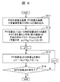
図6は線形補完方式の処理フロー図である。
処理ステップS11では、日射計設置点座標、太陽光発電装置設置点座標、日射量測定値Si(kWh/m2)読み込みを行う。
処理ステップS12では、太陽光発電装置設置点jに近い日射計設置点を3点選定する。そのうえで、その3点を通る三角形A(部分領域)の平面の式のパラメータ(a、b、c)計算を行う。なお、平面の式は、前述のように、(3)式で表わされる。
[数3]
ajx+bjy+cjz+dj=0 ・・・(3)
処理ステップS13では、太陽光発電装置設置点jの日射量zjを算出する。zjの算出は、(4)式で算出されればよい。
[数4]
zj=-(ajxj+bjyj+dj)/cj ・・・ (4)
処理ステップS14では、すべての太陽光発電装置について計算が実施されたか判定し、未完の場合処理ステップS13に戻る。
[数3]
ajx+bjy+cjz+dj=0 ・・・(3)
処理ステップS13では、太陽光発電装置設置点jの日射量zjを算出する。zjの算出は、(4)式で算出されればよい。
[数4]
zj=-(ajxj+bjyj+dj)/cj ・・・ (4)
処理ステップS14では、すべての太陽光発電装置について計算が実施されたか判定し、未完の場合処理ステップS13に戻る。
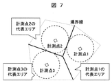
図7は日射量推定方法の他の一例である代表値方式の考え方を示す概念図である。特定の日射計を代表とし、その近隣の太陽光発電装置地点の日射量は、代表の日射量計測値と等しいとみなす手法である。代表とする日射計の選定においては、太陽光発電装置設置点から最も近い位置にある計測点を選定する。この方法の一つにボロノイ図(ボロノイ分割)がある。これは、ある距離空間上の任意の位置に配置された複数個の点(母点)に対して、同一距離空間上の他の点がどの母点に近いかによって領域分けされた図のことである。特に二次元ユークリッド平面の場合、領域の境界線は、各々の母点の二等分線の一部になる。
ボロノイ分割では、距離が均等になるように境界線が決まる。このとき、母点から同一距離にある地点の集合は円で表される。このようにして、各太陽光発電装置設置点の日射量を推定することが可能となる。
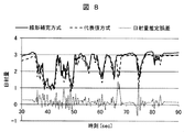
図8に日射量推定値および推定誤差量の計算例を示す。前述の線形補完方式、代表値方式の2つの推定方法によって、ある太陽光発電装置設置点の日射量を推定した例を示している。太い実線の線形補完方式、太い点線の代表値方式は、推定アルゴリズムの違いによって、各時刻の日射量が異なる結果を計算している。これらの差分(細かい点線)を、日射量推定誤差として示している。
この計算結果によれば、2つの推定値は長期的(図の例では10秒オーダー)には同じ変動傾向を示しているが、短期的(図の例では秒オーダー)には差分を発生している。この結果を踏まえて、実運用においては日射量推定値として、線形補完方式、代表値方式、およびこれらの平均値を用いればよく、その値に日射量推定誤差が含まれているとして、各種系統制御に活用していけばよい。
本発明による以上のような機能により、太陽光発電装置発電量および誤差量を計算することができ、これにより系統の需給制御、電圧制御等を高精度かつ誤差リスクを考慮して実施することが可能となる。
つまり図1に一例を示した太陽光発電装置の出力推定装置が求めた結果である出力推定値および出力推定誤差値を電力系統監視装置に反映させることで、次のような配電系統管理上の効果が得られる。
例えば需給制御や電圧制御を実施する電力系統監視装置に対して、出力推定値および出力推定誤差値を与えることで、センサ170が検知する有効電力、無効電力に含まれる太陽光発電装置PVの出力の割合が把握可能となる。これにより、太陽光発電装置PVの出力が急増、急減した場合の潮流量を予測することが可能となり、需給制御や電圧制御が可能か、随時監視し、さらには制御すること可能となる効果を生じる。
また、電力系統監視装置が配電用変電所110、自動電圧調整器SVR、静止形無効電力補償装置SVCを用いた監視、制御を実行するものである時に、起こりうる太陽光発電装置PVの出力変化に備えて、現在の制御量を調整したり、制御応答速度を調整したりすることで、より効率的な監視、制御が可能となる効果を生じる。
さらに電力系統制御装置での他の適用事例として、太陽光発電装置の発電量が把握できることで、線路のセンサの計測値から、負荷量を把握することが可能となる。また、誤差を考慮することで、負荷量の推定誤差量も把握可能となる、これにより、急な太陽光発電装置脱落時を考慮した、過負荷防止や、負荷融通を適切に実施可能となる効果がある。
また、現在の太陽光発電装置発電量を把握することで、急な太陽光発電装置出力変動範囲はせいぜい現在値から太陽光発電装置設備容量最大値まで増加するか、0に減少するかいずれかであると、推定でき、これにより太陽光発電装置出力変化に対する瞬動予備力や電圧制御余裕を最小限にすることが可能となる。これにより、発電機効率低下を抑制し、電圧調整設備容量を低減することが可能となり、系統運用・設備コストを低減できる効果がある。
なお、図1の構成では異方式で日射量とその誤差量を求め、その後推定電力量に変換するという手順を踏んでいるが、これは異方式で日射量を求め、その後推定電力量に変換するとともに、推定電力量の差分として推定電力量の誤差分を求めるという手順を踏んでもよい。
いずれにせよ本発明においては、検知した太陽光発電量に含まれる誤差量が推定できないという課題に対して、異方式演算による推定電力の差分が出力誤差量に相当するという新たな考えのもとに、装置構成し、方法を工夫し、かつ以後の制御に応用可能としたものである。
電力系統の太陽光発電装置出力および推定誤差把握装置、太陽光発電装置出力変化量推定装置として活用することができる。電力系統の需給調整装置の瞬動予備力決定に活用することで、周波数調整装置、経済負荷配分装置等の機能として活用することができる。また電圧調整装置や、配電系統の負荷融通決定装置、配電自動化システムの機能として活用できる。また、配電系統において、太陽光発電などの分散電源の増設に対応した、電圧維持対策、配電設備利用率向上対策として活用することが可能となる。
10:太陽光発電装置出力推定装置,11:表示装置,12:キーボードやマウス等の入力手段,CPU:コンピュータ,14:通信手段,RAM:ランダムアクセスメモリ,DB1:日射計情報データベース,DB2:PV情報データベース,DB3:日射推定データベース,DB4:PV発電出力データベース,DB5:プログラムデータベース,31:日射量計測部,32、33:複数の日射量推定処理部,34:日射推定誤差量算出部,35:経過時間計測部,36:日射再起動処理部,37:日射-太陽光発電出力変換部,100:配電系統,110:配電用変電所,120:ノード,130:太陽光発電装置,140:配電線路,150:負荷,SVR:自動電圧調整器,170:センサ,180:日射計,SVC:静止形無効電力補償装置
Claims (8)
- 日射計測値を元に太陽光発電装置の出力を推定する太陽光発電出力推定方法であって、 日射計設置点情報と日射計計測値および太陽光発電装置設置点情報から、太陽光発電装置設置点における日射量を推定する第1の推定手法と、該第1の推定手法と異なる手法で太陽光発電装置設置点における日射量を推定する第2の推定手法と、推定された日射量と当該太陽光発電装置の定格容量から太陽光発電装置の出力を推定する出力推定手法と、第1と第2の推定手法の差から太陽光発電装置出力の推定誤差を求める誤差推定手法を備えることを特徴とする太陽光発電出力推定方法。
- 請求項1に記載の太陽光発電出力推定方法であって、
前記太陽光発電装置発電量を推定する第1または第2の推定手法は、線形補完方式または代表値方式のいずれかであることを特徴とする太陽光発電出力推定方法。 - 請求項1または請求項2に記載の太陽光発電出力推定方法であって、
日射量推定値および日射量推定誤差から、日射量変動量推定値および日射量変動量推定誤差を求めることを特徴とする太陽光発電出力推定方法。 - 日射計測値を元に太陽光発電装置の出力を推定する太陽光発電出力推定装置であって、 日射計設置点情報と日射計計測値および太陽光発電装置設置点情報から、太陽光発電装置設置点における日射量を推定する第1の推定手段と、該第1の推定手法と異なる手法で太陽光発電装置設置点における日射量を推定する第2の推定手段と、推定された日射量と当該太陽光発電装置の定格容量から太陽光発電装置の出力を推定する出力推定手段と、第1と第2の推定手段の差から太陽光発電装置出力の推定誤差を求める誤差推定手段を備えることを特徴とする太陽光発電出力推定装置。
- 請求項4に記載の太陽光発電出力推定装置であって、
前記太陽光発電装置発電量を推定する第1または第2の推定手段は、線形補完方式または代表値方式のいずれかであることを特徴とする太陽光発電出力推定装置。 - 請求項4または請求項5に記載の太陽光発電出力推定装置であって、
日射量推定値および日射量推定誤差から、日射量変動量推定値および日射量変動量推定誤差を求めることを特徴とする太陽光発電出力推定装置。 - 同一の太陽光発電装置について、その出力を異なる推定手法により推定した推定出力と、その差分から求めた当該太陽光発電装置の出力推定誤差とを、電力系統の制御に使用することを特徴とする電力系統監視装置。
- 請求項7に記載の電力系統監視装置であって、
電力系統監視装置は、前記請求項1から請求項3のいずれか1項に記載の太陽光発電出力推定装置から推定出力と推定出力誤差を得ることを特徴とする電力系統監視装置。
Priority Applications (1)
| Application Number | Priority Date | Filing Date | Title |
|---|---|---|---|
| US15/113,245 US10211777B2 (en) | 2014-01-22 | 2015-01-14 | Photovoltaic power generator output estimation method and device, and power system monitoring device using same |
Applications Claiming Priority (2)
| Application Number | Priority Date | Filing Date | Title |
|---|---|---|---|
| JP2014009218A JP6255251B2 (ja) | 2014-01-22 | 2014-01-22 | 太陽光発電装置の出力推定方法および装置並びにこれを用いた電力系統監視装置 |
| JP2014-009218 | 2014-01-22 |
Publications (1)
| Publication Number | Publication Date |
|---|---|
| WO2015111473A1 true WO2015111473A1 (ja) | 2015-07-30 |
Family
ID=53681280
Family Applications (1)
| Application Number | Title | Priority Date | Filing Date |
|---|---|---|---|
| PCT/JP2015/050727 Ceased WO2015111473A1 (ja) | 2014-01-22 | 2015-01-14 | 太陽光発電装置の出力推定方法および装置並びにこれを用いた電力系統監視装置 |
Country Status (3)
| Country | Link |
|---|---|
| US (1) | US10211777B2 (ja) |
| JP (1) | JP6255251B2 (ja) |
| WO (1) | WO2015111473A1 (ja) |
Cited By (3)
| Publication number | Priority date | Publication date | Assignee | Title |
|---|---|---|---|---|
| US10003300B2 (en) | 2015-10-09 | 2018-06-19 | Sunpower Corporation | Photovoltaic management and module-level power electronics |
| CN112257938A (zh) * | 2020-10-28 | 2021-01-22 | 广州发展新能源股份有限公司 | 一种光伏发电功率预测方法及装置 |
| CN119582210A (zh) * | 2025-02-07 | 2025-03-07 | 国网浙江省电力有限公司温州供电公司 | 一种光伏准入容量分配方法及系统 |
Families Citing this family (8)
| Publication number | Priority date | Publication date | Assignee | Title |
|---|---|---|---|---|
| JP6410962B2 (ja) * | 2015-11-26 | 2018-10-24 | 三菱電機株式会社 | 配電系統管理装置、計測装置、配電系統管理システムおよび発電量推定方法 |
| JP6641007B2 (ja) * | 2016-06-22 | 2020-02-05 | 株式会社日立製作所 | 太陽光出力予測装置、電力系統制御装置及び太陽光出力予測方法 |
| KR101986626B1 (ko) * | 2016-08-26 | 2019-09-30 | 주식회사 엘지화학 | 리튬 이차전지용 음극 및 이를 포함하는 리튬 이차전지 |
| JP6823499B2 (ja) * | 2017-02-28 | 2021-02-03 | 京セラ株式会社 | 情報処理装置及び情報処理装置の制御方法 |
| US11101653B2 (en) * | 2018-10-09 | 2021-08-24 | S&C Electric Company | Solar generation estimation |
| JP7565178B2 (ja) * | 2020-09-01 | 2024-10-10 | 四国計測工業株式会社 | 電力管理装置および複数の発電設備の発電量予測管理方法 |
| JP7574635B2 (ja) * | 2020-12-15 | 2024-10-29 | 株式会社Ihi | 電力供給制御装置、電力供給制御方法、及び電力供給システム |
| CN114896871B (zh) * | 2022-04-22 | 2023-12-22 | 国网江苏省电力有限公司电力科学研究院 | 一种基于最小互信息的光伏出力分解方法 |
Citations (6)
| Publication number | Priority date | Publication date | Assignee | Title |
|---|---|---|---|---|
| JP2006033908A (ja) * | 2004-07-12 | 2006-02-02 | Nippon Telegr & Teleph Corp <Ntt> | 太陽光発電システムの発電量予測方法、装置、およびプログラム |
| JP2011058814A (ja) * | 2009-09-07 | 2011-03-24 | Japan Weather Association | 日射量予測装置、方法及びプログラム |
| JP2012010508A (ja) * | 2010-06-25 | 2012-01-12 | Mitsubishi Heavy Industries Mechatronics Systems Ltd | 発電量予測装置、発電量予測システム、発電量予測方法、及び発電量予測プログラム |
| JP2012044089A (ja) * | 2010-08-23 | 2012-03-01 | Mitsubishi Electric Corp | 発電量推定システム |
| JP2013009492A (ja) * | 2011-06-23 | 2013-01-10 | Hitachi Ltd | 供給電力制御システム、供給電力制御方法、および供給電力制御プログラム |
| JP2013253805A (ja) * | 2012-06-05 | 2013-12-19 | Fuji Electric Co Ltd | 情報処理装置、情報処理装置の制御方法及びプログラム |
Family Cites Families (8)
| Publication number | Priority date | Publication date | Assignee | Title |
|---|---|---|---|---|
| JP2007281060A (ja) | 2006-04-04 | 2007-10-25 | Nippon Telegr & Teleph Corp <Ntt> | 太陽光発電システムの発電予測方法、装置、およびプログラム |
| JP4864803B2 (ja) * | 2007-04-23 | 2012-02-01 | 株式会社東芝 | 電力需給制御装置およびその方法 |
| JP4365429B2 (ja) * | 2007-07-24 | 2009-11-18 | トヨタ自動車株式会社 | 充電情報を表示するナビゲーション装置およびその装置を備えた車両 |
| WO2011104882A1 (ja) * | 2010-02-26 | 2011-09-01 | 東芝三菱電機産業システム株式会社 | 太陽光発電システム |
| JP5600570B2 (ja) | 2010-12-06 | 2014-10-01 | 株式会社日立製作所 | 太陽光発電量予測装置,太陽光発電量予測方法,系統電圧制御装置,系統電圧制御方法 |
| US8165811B2 (en) * | 2011-07-25 | 2012-04-24 | Clean Power Research, L.L.C. | Computer-implemented system and method for determining point-to-point correlation of sky clearness for photovoltaic power generation fleet output estimation |
| JP5339317B1 (ja) * | 2012-07-30 | 2013-11-13 | 祥人 平田 | 気象変動の実時間予測法に基づく再生可能エネルギー出力変動の予測機構 |
| JP6115764B2 (ja) * | 2013-03-14 | 2017-04-19 | オムロン株式会社 | 太陽光発電システム、異常判断処理装置、異常判断処理方法、およびプログラム |
-
2014
- 2014-01-22 JP JP2014009218A patent/JP6255251B2/ja active Active
-
2015
- 2015-01-14 WO PCT/JP2015/050727 patent/WO2015111473A1/ja not_active Ceased
- 2015-01-14 US US15/113,245 patent/US10211777B2/en active Active
Patent Citations (6)
| Publication number | Priority date | Publication date | Assignee | Title |
|---|---|---|---|---|
| JP2006033908A (ja) * | 2004-07-12 | 2006-02-02 | Nippon Telegr & Teleph Corp <Ntt> | 太陽光発電システムの発電量予測方法、装置、およびプログラム |
| JP2011058814A (ja) * | 2009-09-07 | 2011-03-24 | Japan Weather Association | 日射量予測装置、方法及びプログラム |
| JP2012010508A (ja) * | 2010-06-25 | 2012-01-12 | Mitsubishi Heavy Industries Mechatronics Systems Ltd | 発電量予測装置、発電量予測システム、発電量予測方法、及び発電量予測プログラム |
| JP2012044089A (ja) * | 2010-08-23 | 2012-03-01 | Mitsubishi Electric Corp | 発電量推定システム |
| JP2013009492A (ja) * | 2011-06-23 | 2013-01-10 | Hitachi Ltd | 供給電力制御システム、供給電力制御方法、および供給電力制御プログラム |
| JP2013253805A (ja) * | 2012-06-05 | 2013-12-19 | Fuji Electric Co Ltd | 情報処理装置、情報処理装置の制御方法及びプログラム |
Cited By (5)
| Publication number | Priority date | Publication date | Assignee | Title |
|---|---|---|---|---|
| US10003300B2 (en) | 2015-10-09 | 2018-06-19 | Sunpower Corporation | Photovoltaic management and module-level power electronics |
| US10615742B2 (en) | 2015-10-09 | 2020-04-07 | Enphase Energy, Inc. | Photovoltaic management and module-level power electronics |
| US11095249B2 (en) | 2015-10-09 | 2021-08-17 | Enphase Energy, Inc. | Photovoltaic management and module-level power electronics |
| CN112257938A (zh) * | 2020-10-28 | 2021-01-22 | 广州发展新能源股份有限公司 | 一种光伏发电功率预测方法及装置 |
| CN119582210A (zh) * | 2025-02-07 | 2025-03-07 | 国网浙江省电力有限公司温州供电公司 | 一种光伏准入容量分配方法及系统 |
Also Published As
| Publication number | Publication date |
|---|---|
| JP6255251B2 (ja) | 2017-12-27 |
| US10211777B2 (en) | 2019-02-19 |
| JP2015138864A (ja) | 2015-07-30 |
| US20170012580A1 (en) | 2017-01-12 |
Similar Documents
| Publication | Publication Date | Title |
|---|---|---|
| JP6255251B2 (ja) | 太陽光発電装置の出力推定方法および装置並びにこれを用いた電力系統監視装置 | |
| US11619206B2 (en) | System and method for controlling a power generating unit | |
| US9912158B2 (en) | Decentralized generator control | |
| US20160126739A1 (en) | Enhancing power system voltage stability using grid energy storage for voltage support | |
| JP6348862B2 (ja) | 系統安定化制御装置および電力系統制御システム | |
| US20170271882A1 (en) | Decentralized Generator Control | |
| JP6191229B2 (ja) | タップ計画値算出方法及びこれを用いたタップ指令値の決定方法、制御目標値算出方法、並びにタップ計画値算出装置、タップ指令値決定装置、タップ計画値算出プログラム | |
| JP2019535225A (ja) | 発電システムのエネルギー生産及び周波数調整の同時最適化 | |
| US20180262010A1 (en) | Device for Controlling Load Frequency and Method for Controlling Load Frequency | |
| EP3491486A1 (en) | Microgrid power flow monitoring and control | |
| JP6299743B2 (ja) | 電力潮流制御システム、および、電力潮流制御方法 | |
| US20200291922A1 (en) | Model predictive control in local systems | |
| JP6530172B2 (ja) | 電力系統監視装置および電力系統監視方法 | |
| JP6385292B2 (ja) | 発電出力の推定方法、推定装置、及び推定プログラム | |
| JP6244247B2 (ja) | 系統安定度監視装置及び方法 | |
| JP6399950B2 (ja) | 配電系統の電圧調整装置および電圧調整方法 | |
| KR20150059313A (ko) | 송전 한계를 고려한 자동 발전 제어 방법 | |
| JP2014192904A (ja) | 電力系統管理装置、及び方法 | |
| WO2017221343A1 (ja) | 太陽光出力予測装置、電力系統制御装置及び太陽光出力予測方法 | |
| JP6960263B2 (ja) | 電力系統における系統運用支援装置および方法、並びに広域監視保護制御システム | |
| JP6390795B2 (ja) | 配電系統監視システムおよび配電系統監視システムの制御方法 | |
| JP2022134639A (ja) | 電力系統安定化装置および電力系統安定化方法 | |
| JP2014176199A (ja) | 電力貯蔵制御システムおよび電力貯蔵制御方法 | |
| JP7206939B2 (ja) | 発電設備の出力予測システム及び発電設備の出力予測方法 | |
| KR102933358B1 (ko) | 전력계통의 계통 관성 추정 장치 및 방법 |
Legal Events
| Date | Code | Title | Description |
|---|---|---|---|
| 121 | Ep: the epo has been informed by wipo that ep was designated in this application |
Ref document number: 15740041 Country of ref document: EP Kind code of ref document: A1 |
|
| WWE | Wipo information: entry into national phase |
Ref document number: 15113245 Country of ref document: US |
|
| NENP | Non-entry into the national phase |
Ref country code: DE |
|
| 122 | Ep: pct application non-entry in european phase |
Ref document number: 15740041 Country of ref document: EP Kind code of ref document: A1 |