WO2015114674A1 - 集音装置、集音装置の入力信号補正方法および移動機器情報システム - Google Patents
集音装置、集音装置の入力信号補正方法および移動機器情報システム Download PDFInfo
- Publication number
- WO2015114674A1 WO2015114674A1 PCT/JP2014/000412 JP2014000412W WO2015114674A1 WO 2015114674 A1 WO2015114674 A1 WO 2015114674A1 JP 2014000412 W JP2014000412 W JP 2014000412W WO 2015114674 A1 WO2015114674 A1 WO 2015114674A1
- Authority
- WO
- WIPO (PCT)
- Prior art keywords
- signal
- input signal
- power
- input
- sound
- Prior art date
- Legal status (The legal status is an assumption and is not a legal conclusion. Google has not performed a legal analysis and makes no representation as to the accuracy of the status listed.)
- Ceased
Links
Images


Classifications
-
- H—ELECTRICITY
- H04—ELECTRIC COMMUNICATION TECHNIQUE
- H04R—LOUDSPEAKERS, MICROPHONES, GRAMOPHONE PICK-UPS OR LIKE ACOUSTIC ELECTROMECHANICAL TRANSDUCERS; ELECTRIC HEARING AIDS; PUBLIC ADDRESS SYSTEMS
- H04R3/00—Circuits for transducers
- H04R3/005—Circuits for transducers for combining the signals of two or more microphones
-
- G—PHYSICS
- G10—MUSICAL INSTRUMENTS; ACOUSTICS
- G10L—SPEECH ANALYSIS TECHNIQUES OR SPEECH SYNTHESIS; SPEECH RECOGNITION; SPEECH OR VOICE PROCESSING TECHNIQUES; SPEECH OR AUDIO CODING OR DECODING
- G10L21/00—Speech or voice signal processing techniques to produce another audible or non-audible signal, e.g. visual or tactile, in order to modify its quality or its intelligibility
- G10L21/02—Speech enhancement, e.g. noise reduction or echo cancellation
- G10L21/0316—Speech enhancement, e.g. noise reduction or echo cancellation by changing the amplitude
-
- H—ELECTRICITY
- H04—ELECTRIC COMMUNICATION TECHNIQUE
- H04R—LOUDSPEAKERS, MICROPHONES, GRAMOPHONE PICK-UPS OR LIKE ACOUSTIC ELECTROMECHANICAL TRANSDUCERS; ELECTRIC HEARING AIDS; PUBLIC ADDRESS SYSTEMS
- H04R29/00—Monitoring arrangements; Testing arrangements
- H04R29/004—Monitoring arrangements; Testing arrangements for microphones
-
- G—PHYSICS
- G10—MUSICAL INSTRUMENTS; ACOUSTICS
- G10L—SPEECH ANALYSIS TECHNIQUES OR SPEECH SYNTHESIS; SPEECH RECOGNITION; SPEECH OR VOICE PROCESSING TECHNIQUES; SPEECH OR AUDIO CODING OR DECODING
- G10L15/00—Speech recognition
-
- H—ELECTRICITY
- H04—ELECTRIC COMMUNICATION TECHNIQUE
- H04R—LOUDSPEAKERS, MICROPHONES, GRAMOPHONE PICK-UPS OR LIKE ACOUSTIC ELECTROMECHANICAL TRANSDUCERS; ELECTRIC HEARING AIDS; PUBLIC ADDRESS SYSTEMS
- H04R1/00—Details of transducers, loudspeakers or microphones
- H04R1/20—Arrangements for obtaining desired frequency or directional characteristics
- H04R1/32—Arrangements for obtaining desired frequency or directional characteristics for obtaining desired directional characteristic only
- H04R1/40—Arrangements for obtaining desired frequency or directional characteristics for obtaining desired directional characteristic only by combining a number of identical transducers
- H04R1/406—Arrangements for obtaining desired frequency or directional characteristics for obtaining desired directional characteristic only by combining a number of identical transducers microphones
-
- H—ELECTRICITY
- H04—ELECTRIC COMMUNICATION TECHNIQUE
- H04R—LOUDSPEAKERS, MICROPHONES, GRAMOPHONE PICK-UPS OR LIKE ACOUSTIC ELECTROMECHANICAL TRANSDUCERS; ELECTRIC HEARING AIDS; PUBLIC ADDRESS SYSTEMS
- H04R2430/00—Signal processing covered by H04R, not provided for in its groups
- H04R2430/03—Synergistic effects of band splitting and sub-band processing
-
- H—ELECTRICITY
- H04—ELECTRIC COMMUNICATION TECHNIQUE
- H04R—LOUDSPEAKERS, MICROPHONES, GRAMOPHONE PICK-UPS OR LIKE ACOUSTIC ELECTROMECHANICAL TRANSDUCERS; ELECTRIC HEARING AIDS; PUBLIC ADDRESS SYSTEMS
- H04R2499/00—Aspects covered by H04R or H04S not otherwise provided for in their subgroups
- H04R2499/10—General applications
- H04R2499/11—Transducers incorporated or for use in hand-held devices, e.g. mobile phones, PDA's, camera's
-
- H—ELECTRICITY
- H04—ELECTRIC COMMUNICATION TECHNIQUE
- H04R—LOUDSPEAKERS, MICROPHONES, GRAMOPHONE PICK-UPS OR LIKE ACOUSTIC ELECTROMECHANICAL TRANSDUCERS; ELECTRIC HEARING AIDS; PUBLIC ADDRESS SYSTEMS
- H04R2499/00—Aspects covered by H04R or H04S not otherwise provided for in their subgroups
- H04R2499/10—General applications
- H04R2499/13—Acoustic transducers and sound field adaptation in vehicles
Definitions
- the present invention relates to a sound collecting device that collects sound such as voice using a plurality of sound collecting devices.
- a microphone array process for collecting sounds using a plurality of microphones has been devised and widely used.
- the frequency characteristics and gain characteristics of a microphone are not uniform due to factors such as individual differences at the time of manufacture, aging, or installation environment, but vary from individual to individual.
- microphone array processing if there are variations in the frequency characteristics and gain characteristics of the microphones used, the sound collection performance will deteriorate, so it is possible to correct the signals acquired by the microphones so that there is no difference in characteristics between the microphones. Done.
- the sound arriving at the microphone is corrected based on the signal acquired by the microphone
- the correction performed on the collected sound of the target sound is caused by factors such as the position of the acquired sound source being different from the target sound source. Therefore, it is not always an appropriate correction. Even if correction is performed based on the signal obtained from the target sound, there is a possibility that the correction is performed based on the signal obtained by mistakenly acquiring the sound that is not the target sound. It is not always possible to make an appropriate correction for the sound collection.
- the sound collecting device using the conventional microphone array has a problem that there is a possibility that the correction is not suitable for the target sound to be collected.
- the present invention has been made to solve the above-described problem, and corrects signals acquired by a plurality of microphones of a microphone array using sound arriving at the microphones, for sound to be collected. It is an object of the present invention to obtain a sound collecting device that reduces the possibility of performing inappropriate correction.
- the sound collecting device of the present invention for each of a plurality of input signals acquired by a plurality of microphones, the power of the input signal having a value smaller than a prescribed first threshold value is set as the small signal power of the input signal.
- a small signal power acquisition unit that performs correction
- a correction amount setting unit that obtains respective correction amounts for correcting a plurality of input signals based on the respective small signal powers, and respective corrections for correcting a plurality of input signals
- a correction unit that corrects corresponding input signals based on the quantity.
- An input signal correction method for a sound collector of the present invention is a method for correcting an input signal in a sound collector that generates a signal of a target sound to be collected from a plurality of input signals acquired by a plurality of microphones.
- the power of the input signal having a value smaller than a prescribed threshold is set as the small signal power of the input signal
- a correction amount for correcting the input signal corresponding to the small signal power obtained based on the small signal power is obtained, and a signal obtained by correcting the plurality of input signals based on the respective correction amounts is used.
- a sound collector that generates an output signal that emphasizes the sound to be collected, and a route guidance device that performs processing based on a voice recognition result of the output signal output by the sound collector, or an output signal of the sound collector At least one of a call silencer and an active silencer that uses an output signal of the sound collection device is provided.
- the small signal is set to a power smaller than the defined first threshold value as the small signal power of each input signal. Since the correction amount for correcting each input signal based on the power is obtained and each input signal is corrected with the obtained correction amount, there is a possibility that correction is not appropriate for the sound to be collected. Can be obtained.
- the input signal correction method for a sound collector of the present invention the input signal from each microphone constituting the microphone array has a power smaller than the defined first threshold value and the small signal power of each input signal. Since the correction amount for correcting each input signal is obtained based on this small signal power and each input signal is corrected with the obtained correction amount, it is not appropriate for the sound to be collected.
- Correction can be performed with reduced possibility of correction.
- the mobile device information system of the present invention for each of a plurality of input signals acquired by a plurality of microphones, the power of the input signal having a value smaller than a prescribed threshold is set as the small signal power of the input signal. Based on each small signal power, a correction amount for correcting the input signal corresponding to the small signal power is obtained, and a plurality of input signals are corrected based on the respective correction amounts.
- the sound collecting device outputs an output signal that emphasizes the sound to be sounded, and the route guidance device, the communication device, or the active silencer can operate with better performance by using the signal of this good sound.
- vehicle-mounted information system mobile equipment information system
- FIG. 1 is a block diagram showing a configuration of a sound collecting apparatus according to an embodiment of the present invention.
- the sound collector of this embodiment includes a signal correction unit 1 that corrects sound signals (input signals) acquired in a plurality of microphones 21 1 to 21 N (N is a natural number of 2 or more) that constitutes a microphone array 20.
- a signal processing unit 2 for processing the signal corrected by the signal correction unit 1.
- a microphone 21 when there is no need to distinguish a specific microphone, it may be simply referred to as a microphone 21. The same applies to the notation of other blocks and signals.
- input signals xin 1 (n) to xin N (n) input to the signal correction unit 1 are AD (analog digital) in which the sound collecting device includes electric signals of sounds acquired by the microphones 21 1 to 21 N.
- a converter (not shown) digitizes the signal, samples at a specified sampling frequency (for example, 8 kHz), and divides the signal into frames at a specified time (for example, every 10 milliseconds).
- n indicates a frame number for identifying each divided frame.
- (n) may be omitted and simply indicated as xin 1 in some cases.
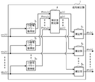
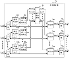
- FIG. 2 is a block diagram illustrating an example of the configuration of the signal correction unit 1.
- the signal correction unit 1 includes small signal power acquisition units 3 1 to 3 N , a correction amount setting unit 4, and correction units 5 1 to 5 N.
- the small signal power acquisition unit 3 determines and outputs the power of the input signal xin having a value smaller than the first threshold defined for the input signal xin as the small signal power Pmin.
- the correction amount setting unit 4 determines a correction amount for correcting the corresponding input signal xin based on the small signal power Pmin output from the small signal power acquisition unit 3.
- the correction unit 5 corrects the input signal xin based on the respective correction amounts determined by the correction amount setting unit 4.
- N small signal power acquisition units 3 1 to 3 N are provided corresponding to N input signals xin 1 to xin N , but one block processes a plurality of input signals. You may comprise so that it may do. The same applies to the correction units 5 1 to 5 N and the like.
- FIG. 3 is a block diagram showing an example of the internal configuration of the small signal power acquisition unit 3.
- the small signal power acquisition unit 3 includes a power calculation unit 6 that calculates the power of the input signal xin, a minimum value tracking unit 7 that calculates a long-term average value of the minimum value of power, and a first value based on the long-term average value of the minimum value of power.
- the threshold value calculation unit 8 calculates a threshold value
- the comparison unit 9 compares the power of the input signal xin with the first threshold value and outputs a small signal power Pmin.
- the small signal power acquisition units 3 1 to 3 N have the same configuration.
- Minimum value tracking unit 7, threshold value calculation unit 8, and comparison unit 9 are executed by a general-purpose processor or hardware and processor composed of peripheral circuits such as DSP (Digital Signal Processor) and RAM (Random Access Memory). It can be realized with software. Each of these blocks can also be realized by hardware such as ASIC (Application Specific Specific Integrated Circuit).
- FIG. 4 is a flowchart showing the processing flow of the sound collecting apparatus of this embodiment.
- the input signal xin 1 (n) of the input sound including noise other than the target sound such as the target sound such as voice or music acquired by the microphones 21 1 to 21 N of the microphone array 20 and the background noise is acquired by the signal correction unit 1.
- ⁇ Xin N (n) is received (ST100).
- Signal correcting unit 1 is input an input signal xin 1 (n) ⁇ xin N (n) a small signal power acquisition unit 3 1 ⁇ 3 N is processed, the input signal xin 1 (n) ⁇ xin N (n) The small signal powers Pmin 1 (n) to Pmin N (n) are output. Details of processing performed by the small signal power acquisition unit 3 will be described below with reference to FIGS. 3 and 4.
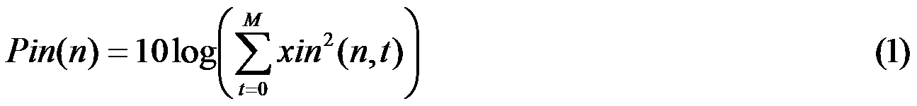
- the power calculation unit 6 of the small signal power acquisition unit 3 calculates the current frame power of the input signal from the input signal xin (n) by the following equation (1), and outputs the input signal power Pin (n). (ST101).
- n is a frame number
- t is a number indicating a discrete time within the frame
- xin (n, t) represents the amplitude at time t of frame n for the input signal xin (n).
- M 80.
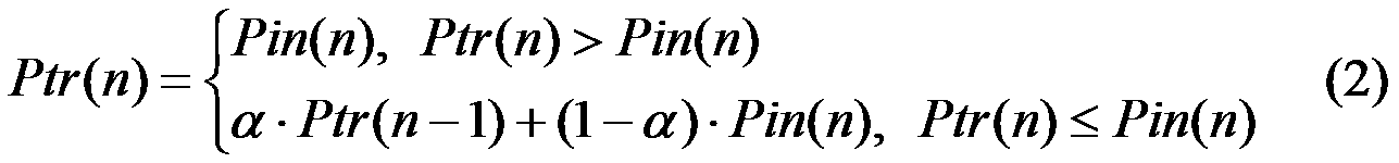
- the minimum value tracking unit 7 that has received the input signal power Pin (n) output from the power calculation unit 6 tracks the minimum value (minimum power) of the input signal power Pin (n) and calculates the long-term average value of the minimum value. (ST102). Specifically, the minimum value tracking unit 7 calculates the long-term average value Ptr (n) of the minimum value of the input signal power Pin (n) according to the following equation (2). The minimum value tracking unit 7 outputs the calculated long-term average value Ptr (n) to the threshold value calculation unit 8.
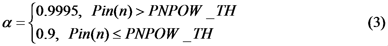
- ⁇ is a time constant for forgetting, and is given by, for example, Expression (3) below.
- PNPOW_TH is a threshold value defined in advance.
- the forgetting factor ⁇ is increased to make the forgetting speed moderate.
- the long-term average value Ptr (n) of the minimum value of the input signal power Pin (n) The influence of the power of the target sound can be suppressed, and the tracking accuracy of the minimum value of the input signal power Pin (n) can be improved.
- the threshold value calculation unit 8 adds the numerical value PADD (n) defined to the long-term average value Ptr (n) input according to the following equation (4), and the first value of the input signal xin (n)
- a small signal power threshold value Pth (n) which is a threshold value, is defined and output (ST103).
- a suitable example of the numerical value PADD (n) in this embodiment is a fixed value of 3 dB. However, it may be changed as appropriate for each frame, for example, according to the type of input sound, etc., so that the input signal is corrected properly.
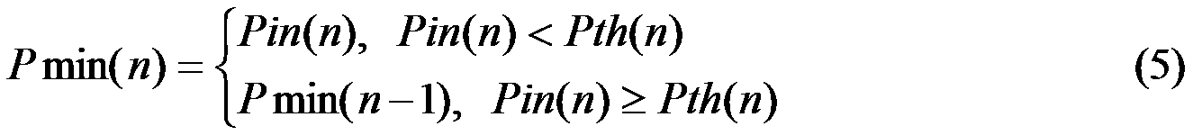
- the comparison unit 9 compares the input signal power Pin (n) with the small signal power threshold value Pth (n) according to the following equation (5), and the small signal power Pmin (n) of the input signal xin (n). Is obtained and output (ST104).
- Pin (n) is lower than Pth (n)
- Pin (n) is output as Pmin (n).
- Pmin (n ⁇ 1) which is the value of the previous frame is output.
- the comparison unit 9 stores the small signal power Pmin (n) of the output input signal xin (n) for use in the processing of the next frame.
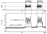
- FIG. 5 shows the change of the waveform with the lapse of time of the input signal xin from which the voice is acquired, and (B) shows the change of the power of the input signal xin with the lapse of time.
- a solid line B1 represents the input signal power Pin calculated by the power calculation unit 6.
- a thick solid line B2 is the small signal power threshold value Pth calculated by the threshold value calculation unit 8.
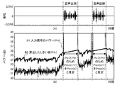
- FIG. 6 is a graph obtained by enlarging a part of FIG. 5B in the vertical axis direction.
- the small signal power Pmin of the previous frame is not the input signal power Pin but the small signal power Pmin of the frame. Therefore, it is possible to suppress the influence of the input signal power Pin in the section including the target sound, on the small signal power Pmin.
- the correction amount setting unit 4 that has received the small signal powers Pmin 1 (n) to Pmin N (n) output from each of the small signal power acquisition units 3 1 to 3 N performs correction for correcting the gain of each microphone 21.
- a correction gain g (n) which is a quantity, is calculated and obtained (ST105).
- an example of the calculation of the correction amount an example of a reference microphone 21 1.
- the other microphones 21 2 - may be referenced to either the 21 N instead of on the basis of the microphone 21 1.
- the microphone 21 closest to the sound source can be used as a reference. Note that, by using any one of the microphones 21 as a reference, it is possible to eliminate the need to set a power reference for obtaining the correction amount in advance.
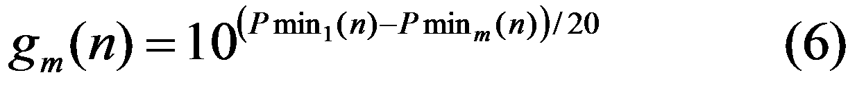
- Correction amount setting unit 4 is at the same level, each of the small signal power Pmin 1 (n) ⁇ Pmin N (n) of the reference small-signal power Pmin 1 (n) according to the microphone 21 1 ⁇ 21 N according to the microphone 21 1 In such a manner, the correction gain g m (n) is calculated according to the following equation (6). Note that m is a natural number of 1 or more and N or less.
- the correction amount setting unit 4 outputs the calculated correction gains g 1 (n) to g N (n) to the correction units 5 1 to 5 N , respectively.
- the correction units 5 1 to 5 N that have received the correction gains g 1 (n) to g N (n) correct the input signals xin 1 (n) to xin N (n) by the following equation (7) (ST106).
- m is a natural number of 1 or more and N or less.
- xin 1 (n ) yin 1 (n) It is.
- Correction unit 5 (referred to as correction signal) input signal xin 1 (n) ⁇ xin N (n) a correction signal yin outputs 1 (n) ⁇ yin N (n) to the signal processing section 2.
- the signal processing unit 2 that has received the correction signals yin 1 (n) to yin N (n) uses the correction signals yin 1 (n) to yin N (n), for example, a known method such as a delay sum method or a maximum likelihood method. Emphasis processing is performed and an output signal is output (ST107).
- the first threshold value of the power of each input signal is tracked by tracking the minimum value of the power for each input signal from each microphone of the microphone array.
- the small signal power threshold is defined, the input signal power smaller than the small signal power threshold is defined as the small signal power, and the input signal from each microphone is corrected based on the small signal power.
- the correction amount was calculated.
- the input signal can be corrected based on an input signal whose power is lower than a specified threshold value, so that the possibility of improper correction for the sound to be collected is reduced, and the microphone is reduced.
- the input signal acquired in step 1 can be corrected. This is because omnidirectional sound such as background noise is suitable for input signal correction to reduce differences in microphone characteristics, and input signals with low power are suitable for diffused omnidirectional sound. This is because it can be regarded as a signal.
- the first threshold value is defined by tracking the minimum value of the power of the input signal from the microphone, it is not necessary to determine this threshold value in advance, and the sound collecting device can be used in an environment. It is possible to compensate for differences in characteristics between microphones in a flexible manner.
- control is performed according to the minimum value (minimum power) of the power of the input signal, but it is also possible to improve the accuracy of correction by analyzing the state of the input signal.
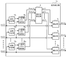
- FIG. 7 is a block diagram showing a configuration of the signal correction unit 1b of the sound collector according to Embodiment 2 of the present invention.
- the overall configuration of the sound collector of the second embodiment is the same as that of the first embodiment. 7 differs from the first embodiment in that a signal determination unit 10 that analyzes an input signal is provided, and an analysis result of the signal determination unit 10 is input to the small signal power acquisition unit 3b.
- the signal determination unit 10 can be realized by a processor and a program executed by the processor, as well as other blocks, or by hardware such as an ASIC.
- the signal correction unit 1b receives the input signals xin 1 (n) to xin N (n) as in the first embodiment.
- the input signals xin 1 (n) to xin N (n) received by the signal determination unit 10 are analyzed.
- the signal determination unit 10 determines whether the received input signal xin 1 is, for example, voice or noise, and outputs the result as determination information to the small signal power acquisition unit 3b.
- a method for analyzing the input signals xin 1 (n) to xin N (n) for example, a method such as autocorrelation analysis may be used.
- the small signal power acquisition unit 3b stops tracking of the minimum power when the input signal is not noise, for example, and performs tracking of the minimum power when it is determined as noise. .
- Other processes are the same as those in the first embodiment.
- the minimum power tracking process by controlling the minimum power tracking process using the result of analyzing the state of the input signal, more accurate tracking can be performed and precise gain correction can be performed. It becomes. This is particularly effective when voice is frequently mixed into the input signal or when high level noise is mixed due to the microphone being hit.
- Embodiment 3 FIG.
- control is performed in accordance with the minimum power of the entire frequency band of the input signal.
- the input signal is converted into the frequency domain, and the correction is subdivided for each spectral component or each band of the input signal. Therefore, it is possible to perform more fine correction.
- FIG. 8 is a block diagram showing the configuration of the signal correction unit 1c of the sound collector according to Embodiment 3 of the present invention.
- the overall configuration of the sound collecting device of the third embodiment is the same as that of the first embodiment. 8 differs from the first embodiment in that an FFT unit (spectral transform unit) 11 that performs Fast Fourier Transform (FFT) processing on an input signal, and an inverse FFT ( An IFFT section (inverse spectrum transform section) 12 that performs IFFT (Inverse FFT) processing is provided.
- FFT unit spectral transform unit
- An IFFT section inverse spectrum transform section
- IFFT Inverse FFT
- the other configurations are the same as those in FIG. 2, but the small signal power extraction unit 3c, the correction amount setting unit 4c, and the correction unit 5c process the spectrum.
- the FFT unit 11 and the IFFT unit 12 can be realized by a processor and a program executed by the processor, as well as other blocks, or by hardware such as an ASIC.
- FFT processing is performed on the input signal xin (n) to which the FFT unit 11 is input.
- FFT analysis shown in the following equation (8) is performed to convert the input signal xin (n) into the power spectrum Xin (n, k).
- FFT (•) represents FFT analysis
- K is the total number of power spectra obtained by this processing
- k is a number (spectrum number) from 0 to K ⁇ 1 attached to the obtained power spectrum.
- the notation of the spectrum number is omitted.
- the small signal power acquisition unit 3c When the small signal power acquisition unit 3c receives the power spectrum Xin (n, k) output from the FFT unit 11, the small signal power acquisition unit 3c uses the same method as that in the first embodiment to determine the power that is the second threshold value for each spectrum. A spectrum threshold value is obtained, and a small signal power spectrum Xmin (n, k) is determined and output based on the threshold value.
- the correction amount setting unit 4c uses the small signal power spectra Xmin 1 (n, k) to Xmin N (n, k) corresponding to the input signals xin 1 (n) to xin N (n), respectively.
- Spectral correction gains G 1 (n, k) to G N (n, k), which are correction amounts for each spectrum, are calculated in the same manner as in the first embodiment.
- the correction unit 5c corrects the power spectrum Xin (n, k) of the corresponding input signal xin (n) for each spectrum by the following equation (9).
- m is a natural number of 1 or more and N or less.
- the IFFT unit 12 reconverts the corresponding corrected power spectra Yin 1 (n, k) to Yin N (n, k) into signals in the time domain by IFFT processing, and corrects the corrected signals yin 1 (n) to yin N (n) is output to the signal processor 2.
- the subsequent processing is the same as in the first embodiment.
- the correction amount is calculated and corrected for each power spectrum obtained by performing FFT processing on the input signal xin (n).
- the frequency characteristics and the amplitude can be made uniform every time, and more precise correction can be performed.
- Embodiment 4 Implementation in which the sound collecting device described in the first to third embodiments is incorporated into a mobile device information system including a route guidance device or a communication device mounted on a mobile device such as an automobile or a ship. A form is demonstrated.
- the in-vehicle information system will be described as an example of the mobile device information system.
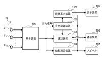
- FIG. 10 is a block diagram showing an example of the configuration of the in-vehicle information system according to this embodiment.
- the in-vehicle information system according to this embodiment includes a sound collection device 100 according to any of the first to third embodiments, a route guidance device 101, a voice recognition device 102, a call device 103, an active silencer 104, a microphone array. 20, a display device 105, a communication device 106, and a speaker 107.
- the configuration shown in FIG. 10 is merely an example, and various other devices can be combined.
- the microphone array 20 inputs the acquired sound signal to the sound collector 100.
- the sound collector 100 performs any of the operations described in the first to third embodiments and outputs an output signal.
- the voice recognition device 102, the call device 103, and the active silencer 104 receive the output signal output from the sound collection device 100.
- the voice recognition device 102 performs voice recognition processing on the received output signal of the sound collecting device 100 and outputs an instruction or the like issued by the user to the route guidance device 101 or the call device 103.
- the route guidance device 101 Upon receiving the instruction from the voice recognition device 102, the route guidance device 101 performs a designated route guidance process, displays a route guidance image on the display device 105, outputs a route guidance voice or the like from the speaker 107, and the like. To do.
- the call device 103 that has received the instruction from the voice recognition device 102 controls the communication device 106. For example, when it is an instruction to start a call, the call device 103 controls the communication device 106 to connect a communication line with a communication partner. Then, the output signal received from the sound collection device 100 is output to the communication device 106. Communication device 106 communicates with a communication partner via a communication line, and outputs the received signal to call device 103. The communication device 103 outputs the signal received from the communication device 106 from the speaker 107.
- the active silencer 104 also predicts environmental noise in the vehicle interior using the output signal received from the sound collector 100, generates an acoustic signal that cancels the environmental noise, and outputs it from the speaker 107. Reduce noise.
- the sound collecting device 100 of the in-vehicle information system uses the sound arriving at the microphone to reduce the possibility of performing inappropriate correction on the sound to be collected, Since the signal acquired by the microphone can be corrected, a good output signal can be obtained. Thereby, the performance of the process performed using sound, such as an audio
- the sound collection device or the sound collection method of the present invention corrects the sound signal acquired by the microphone array so that the characteristic difference between the microphones is reduced without requiring the target sound to be collected. Therefore, it is possible to generate a signal of a good collected sound, which is useful in a system that performs processing based on the collected sound, such as an in-vehicle information system such as a car navigation system.
Landscapes
- Engineering & Computer Science (AREA)
- Signal Processing (AREA)
- Physics & Mathematics (AREA)
- Acoustics & Sound (AREA)
- Health & Medical Sciences (AREA)
- Otolaryngology (AREA)
- General Health & Medical Sciences (AREA)
- Computational Linguistics (AREA)
- Quality & Reliability (AREA)
- Audiology, Speech & Language Pathology (AREA)
- Human Computer Interaction (AREA)
- Multimedia (AREA)
- Circuit For Audible Band Transducer (AREA)
- Obtaining Desirable Characteristics In Audible-Bandwidth Transducers (AREA)
Abstract
Description
このように従来のマイクロホンアレーを用いた集音装置は、集音対象の目的音に適さない補正をしてしまう可能性があるという問題があった。
この発明の集音装置の入力信号補正方法は、複数のマイクロホンで取得された複数の入力信号から集音する対象の音の信号を生成する集音装置における入力信号の補正方法であって、規定されたしきい値よりも小さい入力信号のパワーをその入力信号の小信号パワーとするステップと、入力信号を補正するためのそれぞれの補正量を当該入力信号の小信号パワーに基づいて求めるステップと、入力信号のそれぞれをその入力信号を補正するための補正量に基づいて補正するステップと、を備えるようにしたものである。
この発明の移動機器情報システムは、複数のマイクロホンで取得された複数の入力信号のそれぞれについて、規定されるしきい値よりも値の小さい入力信号のパワーをその入力信号の小信号パワーとし、それぞれのこの小信号パワーに基づいて求めたその小信号パワーに対応する入力信号を補正するための補正量を求め、それぞれのこの補正量に基づいて前記複数の入力信号をそれぞれ補正した信号を用いて集音対象の音を強調した出力信号を生成する集音装置と、その集音装置が出力した出力信号の音声認識結果に基づいて処理を行う経路案内装置、または集音装置の出力信号を用いる通話装置、または集音装置の出力信号を用いる能動消音装置の少なくともいずれか一つを備えるようにしたものである。
この発明の集音装置の入力信号補正方法によれば、マイクロホンアレーを構成する各マイクロホンからの入力信号について、規定された第1のしきい値よりも小さいパワーをそれぞれの入力信号の小信号パワーとして、この小信号パワーに基づいてそれぞれの入力信号を補正するための補正量を求めて、各入力信号を求めた補正量で補正するようにしたので、集音対象の音に対して適切でない補正をする可能性を低減した補正をすることができる。
この発明の移動機器情報システムによれば、複数のマイクロホンで取得された複数の入力信号のそれぞれについて、規定されるしきい値よりも値の小さい入力信号のパワーをその入力信号の小信号パワーとし、それぞれのこの小信号パワーに基づいてその小信号パワーに対応する入力信号を補正するための補正量を求め、それぞれのこの補正量に基づいて複数の入力信号をそれぞれ補正した信号を用いて集音対象の音を強調した出力信号を集音装置が出力し、経路案内装置、通話装置または能動消音装置はこの良好な音の信号を用いることでより良好な性能で動作をすることができる。
図1はこの発明の実施の形態に係る集音装置の構成を示すブロック図である。この実施の形態の集音装置は、マイクロホンアレー20を構成する複数のマイクロホン211~21N(Nは2以上の自然数)において取得された音の信号(入力信号)を補正する信号補正部1と信号補正部1で補正された信号を処理する信号処理部2を備えている。なお、以降の説明では例えば特定のマイクロホンを区別する必要が無い場合に単にマイクロホン21と記す場合がある。これは他のブロックおよび信号の表記においても同様である。
これにより、規定のしきい値よりもパワーの小さい入力信号に基づいて入力信号の補正を行うことができるので、集音対象の音に対して適切でない補正をする可能性を低減して、マイクロホンで取得した入力信号の補正を行うことができる。これは、マイクロホンの特性の違いを小さくするための入力信号の補正には例えば暗騒音などのような無指向性の音が適しており、パワーの小さい入力信号は拡散した無指向性の音の信号とみなせるためである。
実施の形態1では、入力信号のパワーの最小値(最小パワー)に応じた制御を行っているが、入力信号の様態を分析して補正の精度を向上させることも可能である。
なお、信号判定部10は他のブロックと同様にプロセッサおよびプロセッサで実行されるプログラムで実現したり、ASIC等のハードウェアで実現したりすることが可能である。
実施の形態1では、入力信号の全周波数帯域の最小パワーに応じた制御を行っているが、入力信号を周波数領域に変換し、入力信号のスペクトル成分毎、あるいは帯域毎に補正を細分化することで、更にきめ細やかな補正を行うことも可能である。
なお、FFT部11、IFFT部12は他のブロックと同様にプロセッサとプロセッサで実行されるプログラムで実現したり、ASIC等のハードウェアで実現したりすることが可能である。
上述の実施の形態1から実施の形態3で説明した集音装置を、自動車や船舶等の移動機器に搭載される経路案内装置やあるいは通話装置などを備えた移動機器情報システムに組み込んだ実施の形態を説明する。なお、以下では車載情報システムを移動機器情報システムの例として説明する。
Claims (8)
- 複数のマイクロホンで取得された複数の入力信号のそれぞれについて、規定される第1のしきい値よりも値の小さい前記入力信号のパワーをその入力信号の小信号パワーとする小信号パワー取得部と、
前記複数の入力信号を補正するためのそれぞれの補正量を前記入力信号のそれぞれの前記小信号パワーに基づいて求める補正量設定部と、
前記複数の入力信号を補正するためのそれぞれの前記補正量に基づいて前記入力信号をそれぞれ補正する補正部と、
を備えることを特徴とする集音装置。 - 前記小信号パワー抽出部は、前記複数の入力信号のそれぞれについて、前記入力信号のパワーの最小値の長期平均値に基づいて前記第1のしきい値を規定することを特徴とする請求項1に記載の集音装置。
- 前記補正量設定部は、前記複数の入力信号のそれぞれの前記小信号パワーのうちのいずれか一つを基準とし、前記複数の入力信号を補正するためのそれぞれの前記補正量を、当該補正量で補正される前記入力信号の前記小信号パワーと前記基準とした小信号パワーに基づいて求めることを特徴とする請求項1または請求項2に記載の集音装置。
- 前記入力信号を周波数領域の信号であるスペクトルに変換するスペクトル変換部と、
周波数領域の信号であるスペクトルを時間領域の信号に変換するスペクトル逆変換部と、を備え、
前記小信号パワー取得部は前記スペクトル変換部で変換された前記入力信号のスペクトルについて規定される第2のしきい値よりも小さい前記入力信号のパワースペクトルをその入力信号の小信号パワースペクトルとし、
前記補正量設定部は前記入力信号の前記小信号パワースペクトルに基づいて当該入力信号のスペクトルを補正するための補正量を求め、
前記補正部は前記入力信号のスペクトルを前記補正量設定部で求められた当該入力信号のスペクトルを補正するための補正量に基づいて補正し、
前記スペクトル逆変換部は前記補正部において補正された前記入力信号のスペクトルを時間領域の信号に変換することを特徴とする請求項1から請求項3のいずれか一項に記載の集音装置。 - 前記入力信号を分析して当該入力信号の状態を判定した判定情報を出力する信号判定部を備え、
前記小信号パワー取得部は前記判定情報を用いて前記小信号パワーまたは小信号パワースペクトルを取得する処理を実施することを特徴とする請求項1から請求項4のいずれか一項に記載の集音装置。 - 複数のマイクロホンで取得された複数の入力信号から集音する対象の音の信号を生成する集音装置における前記入力信号の補正方法であって、
規定されたしきい値よりも小さい前記入力信号のパワーをその入力信号の小信号パワーとするステップと、
前記入力信号を補正するためのそれぞれの補正量を当該入力信号の前記小信号パワーに基づいて求めるステップと、
前記入力信号のそれぞれをその入力信号を補正するための前記補正量に基づいて補正するステップと、
を備えることを特徴とする集音装置の入力信号補正方法。 - 前記複数の入力信号のそれぞれの前記パワーを計算するステップと、
前記複数の入力信号のそれぞれについて前記パワーの最小値の長期平均値を求めるステップと、
前記複数の入力信号のそれぞれの前記長期平均値に基づいてその長期平均値に対応する前記入力信号の前記しきい値をそれぞれ規定するステップと、
を備えることを特徴とする請求項6に記載の集音装置の入力信号補正方法。 - 複数のマイクロホンで取得された複数の入力信号のそれぞれについて、規定されるしきい値よりも値の小さい前記入力信号のパワーをその入力信号の小信号パワーとし、それぞれのこの小信号パワーに基づいてその小信号パワーに対応する前記入力信号を補正するための補正量を求め、それぞれのこの補正量に基づいて前記複数の入力信号をそれぞれ補正した信号を用いて集音対象の音を強調した出力信号を生成する集音装置と、
前記集音装置が出力した前記出力信号の音声認識結果に基づいて処理を行う経路案内装置、または前記出力信号を用いる通話装置、または前記出力信号を用いる能動消音装置の少なくともいずれか一つを備えることを特徴とする移動機器情報システム。
Priority Applications (5)
| Application Number | Priority Date | Filing Date | Title |
|---|---|---|---|
| JP2015559605A JP6048596B2 (ja) | 2014-01-28 | 2014-01-28 | 集音装置、集音装置の入力信号補正方法および移動機器情報システム |
| PCT/JP2014/000412 WO2015114674A1 (ja) | 2014-01-28 | 2014-01-28 | 集音装置、集音装置の入力信号補正方法および移動機器情報システム |
| US15/025,975 US9674607B2 (en) | 2014-01-28 | 2014-01-28 | Sound collecting apparatus, correction method of input signal of sound collecting apparatus, and mobile equipment information system |
| DE112014006281.2T DE112014006281T5 (de) | 2014-01-28 | 2014-01-28 | Tonsammelvorrichtung, Korrekturverfahren für Eingangssignal von Tonsammelvorrichtung und Mobilgeräte-Informationssystem |
| CN201480068414.6A CN105830152B (zh) | 2014-01-28 | 2014-01-28 | 集音装置、集音装置的输入信号校正方法以及移动设备信息系统 |
Applications Claiming Priority (1)
| Application Number | Priority Date | Filing Date | Title |
|---|---|---|---|
| PCT/JP2014/000412 WO2015114674A1 (ja) | 2014-01-28 | 2014-01-28 | 集音装置、集音装置の入力信号補正方法および移動機器情報システム |
Publications (1)
| Publication Number | Publication Date |
|---|---|
| WO2015114674A1 true WO2015114674A1 (ja) | 2015-08-06 |
Family
ID=53756307
Family Applications (1)
| Application Number | Title | Priority Date | Filing Date |
|---|---|---|---|
| PCT/JP2014/000412 Ceased WO2015114674A1 (ja) | 2014-01-28 | 2014-01-28 | 集音装置、集音装置の入力信号補正方法および移動機器情報システム |
Country Status (5)
| Country | Link |
|---|---|
| US (1) | US9674607B2 (ja) |
| JP (1) | JP6048596B2 (ja) |
| CN (1) | CN105830152B (ja) |
| DE (1) | DE112014006281T5 (ja) |
| WO (1) | WO2015114674A1 (ja) |
Cited By (3)
| Publication number | Priority date | Publication date | Assignee | Title |
|---|---|---|---|---|
| JP2017188762A (ja) * | 2016-04-05 | 2017-10-12 | 日本電信電話株式会社 | レベル差補正装置、レベル差補正方法、レベル差補正プログラム、および記録媒体 |
| JP2018031897A (ja) * | 2016-08-24 | 2018-03-01 | 富士通株式会社 | 利得調整装置、利得調整方法および利得調整プログラム |
| JP2021145324A (ja) * | 2020-03-10 | 2021-09-24 | ペキン シャオミ パインコーン エレクトロニクス カンパニー, リミテッド | 収音音量制御方法、装置及び記憶媒体 |
Families Citing this family (2)
| Publication number | Priority date | Publication date | Assignee | Title |
|---|---|---|---|---|
| CN107509155B (zh) * | 2017-09-29 | 2020-07-24 | 广州视源电子科技股份有限公司 | 一种阵列麦克风的校正方法、装置、设备及存储介质 |
| EP4156719A1 (en) * | 2021-09-28 | 2023-03-29 | GN Audio A/S | Audio device with microphone sensitivity compensator |
Citations (8)
| Publication number | Priority date | Publication date | Assignee | Title |
|---|---|---|---|---|
| JPH02272836A (ja) * | 1989-04-14 | 1990-11-07 | Oki Electric Ind Co Ltd | 音声区間検出方式 |
| JPH07152397A (ja) * | 1993-11-29 | 1995-06-16 | Sony Corp | 音声区間検出方法、並びに音声通信装置および音声認識装置 |
| JPH10301600A (ja) * | 1997-04-30 | 1998-11-13 | Oki Electric Ind Co Ltd | 音声検出装置 |
| JP2000250568A (ja) * | 1999-02-26 | 2000-09-14 | Kobe Steel Ltd | 音声区間検出装置 |
| JP2010139571A (ja) * | 2008-12-09 | 2010-06-24 | Fujitsu Ltd | 音声加工装置及び音声加工方法 |
| JP2010232717A (ja) * | 2009-03-25 | 2010-10-14 | Toshiba Corp | 受音信号処理装置、方法およびプログラム |
| JP2010250152A (ja) * | 2009-04-17 | 2010-11-04 | Secom Co Ltd | 発声検出装置 |
| JP2011124873A (ja) * | 2009-12-11 | 2011-06-23 | Oki Electric Industry Co Ltd | 音源分離装置、方法及びプログラム |
Family Cites Families (19)
| Publication number | Priority date | Publication date | Assignee | Title |
|---|---|---|---|---|
| JPH10139571A (ja) * | 1996-11-05 | 1998-05-26 | Seibu Trading:Kk | 陶磁器の絵付方法 |
| JP3540988B2 (ja) | 2000-07-17 | 2004-07-07 | 日本電信電話株式会社 | 発音体指向性補正方法およびその装置 |
| JP2002099297A (ja) | 2000-09-22 | 2002-04-05 | Tokai Rika Co Ltd | マイクロフォン装置 |
| FR2824978B1 (fr) * | 2001-05-15 | 2003-09-19 | Wavecom Sa | Dispositif et procede de traitement d'un signal audio |
| JP2002354576A (ja) * | 2001-05-25 | 2002-12-06 | Sony Corp | ノイズキャンセラー装置及びノイズキャンセル方法 |
| EP1453348A1 (de) | 2003-02-25 | 2004-09-01 | AKG Acoustics GmbH | Selbstkalibrierung von Arraymikrofonen |
| KR20070050058A (ko) * | 2004-09-07 | 2007-05-14 | 코닌클리케 필립스 일렉트로닉스 엔.브이. | 향상된 잡음 억제를 구비한 전화통신 디바이스 |
| JP4262703B2 (ja) * | 2005-08-09 | 2009-05-13 | 本田技研工業株式会社 | 能動型騒音制御装置 |
| EP1931169A4 (en) * | 2005-09-02 | 2009-12-16 | Japan Adv Inst Science & Tech | Post filter for microphone array |
| US8275120B2 (en) * | 2006-05-30 | 2012-09-25 | Microsoft Corp. | Adaptive acoustic echo cancellation |
| JP5070993B2 (ja) * | 2007-08-27 | 2012-11-14 | 富士通株式会社 | 音処理装置、位相差補正方法及びコンピュータプログラム |
| JP4886715B2 (ja) * | 2007-08-28 | 2012-02-29 | 日本電信電話株式会社 | 定常率算出装置、雑音レベル推定装置、雑音抑圧装置、それらの方法、プログラム及び記録媒体 |
| US8411880B2 (en) * | 2008-01-29 | 2013-04-02 | Qualcomm Incorporated | Sound quality by intelligently selecting between signals from a plurality of microphones |
| CN102044243B (zh) * | 2009-10-15 | 2012-08-29 | 华为技术有限公司 | 语音激活检测方法与装置、编码器 |
| CN101867853B (zh) * | 2010-06-08 | 2014-11-05 | 中兴通讯股份有限公司 | 基于传声器阵列的语音信号处理方法及装置 |
| JP5110614B2 (ja) * | 2010-12-20 | 2012-12-26 | 株式会社日本製鋼所 | 狭帯域能動騒音制御方法および狭帯域能動騒音制御装置 |
| DE112011104737B4 (de) * | 2011-01-19 | 2015-06-03 | Mitsubishi Electric Corporation | Geräuschunterdrückungsvorrichtung |
| FR2976710B1 (fr) * | 2011-06-20 | 2013-07-05 | Parrot | Procede de debruitage pour equipement audio multi-microphones, notamment pour un systeme de telephonie "mains libres" |
| CN103440872B (zh) * | 2013-08-15 | 2016-06-01 | 大连理工大学 | 瞬态噪声的去噪方法 |
-
2014
- 2014-01-28 WO PCT/JP2014/000412 patent/WO2015114674A1/ja not_active Ceased
- 2014-01-28 DE DE112014006281.2T patent/DE112014006281T5/de active Pending
- 2014-01-28 JP JP2015559605A patent/JP6048596B2/ja active Active
- 2014-01-28 CN CN201480068414.6A patent/CN105830152B/zh active Active
- 2014-01-28 US US15/025,975 patent/US9674607B2/en active Active
Patent Citations (8)
| Publication number | Priority date | Publication date | Assignee | Title |
|---|---|---|---|---|
| JPH02272836A (ja) * | 1989-04-14 | 1990-11-07 | Oki Electric Ind Co Ltd | 音声区間検出方式 |
| JPH07152397A (ja) * | 1993-11-29 | 1995-06-16 | Sony Corp | 音声区間検出方法、並びに音声通信装置および音声認識装置 |
| JPH10301600A (ja) * | 1997-04-30 | 1998-11-13 | Oki Electric Ind Co Ltd | 音声検出装置 |
| JP2000250568A (ja) * | 1999-02-26 | 2000-09-14 | Kobe Steel Ltd | 音声区間検出装置 |
| JP2010139571A (ja) * | 2008-12-09 | 2010-06-24 | Fujitsu Ltd | 音声加工装置及び音声加工方法 |
| JP2010232717A (ja) * | 2009-03-25 | 2010-10-14 | Toshiba Corp | 受音信号処理装置、方法およびプログラム |
| JP2010250152A (ja) * | 2009-04-17 | 2010-11-04 | Secom Co Ltd | 発声検出装置 |
| JP2011124873A (ja) * | 2009-12-11 | 2011-06-23 | Oki Electric Industry Co Ltd | 音源分離装置、方法及びプログラム |
Cited By (5)
| Publication number | Priority date | Publication date | Assignee | Title |
|---|---|---|---|---|
| JP2017188762A (ja) * | 2016-04-05 | 2017-10-12 | 日本電信電話株式会社 | レベル差補正装置、レベル差補正方法、レベル差補正プログラム、および記録媒体 |
| JP2018031897A (ja) * | 2016-08-24 | 2018-03-01 | 富士通株式会社 | 利得調整装置、利得調整方法および利得調整プログラム |
| JP2021145324A (ja) * | 2020-03-10 | 2021-09-24 | ペキン シャオミ パインコーン エレクトロニクス カンパニー, リミテッド | 収音音量制御方法、装置及び記憶媒体 |
| US11272307B2 (en) | 2020-03-10 | 2022-03-08 | Beijing Xiaomi Pinecone Electronics Co., Ltd. | Method and device for controlling recording volume, and storage medium |
| JP7045423B2 (ja) | 2020-03-10 | 2022-03-31 | ペキン シャオミ パインコーン エレクトロニクス カンパニー, リミテッド | 収音音量制御方法、装置及び記憶媒体 |
Also Published As
| Publication number | Publication date |
|---|---|
| JP6048596B2 (ja) | 2016-12-21 |
| US9674607B2 (en) | 2017-06-06 |
| US20160241954A1 (en) | 2016-08-18 |
| JPWO2015114674A1 (ja) | 2017-03-23 |
| CN105830152A (zh) | 2016-08-03 |
| DE112014006281T5 (de) | 2016-10-20 |
| CN105830152B (zh) | 2019-09-06 |
Similar Documents
| Publication | Publication Date | Title |
|---|---|---|
| KR100883712B1 (ko) | 음원 방향 추정 방법, 및 음원 방향 추정 장치 | |
| JP4916394B2 (ja) | エコー抑圧装置、エコー抑圧方法及びコンピュータプログラム | |
| EP2773137B1 (en) | Microphone sensitivity difference correction device | |
| JP4912036B2 (ja) | 指向性集音装置、指向性集音方法、及びコンピュータプログラム | |
| CN1122963C (zh) | 用于测量多个传感器处的信号电平和延迟的方法与装置 | |
| US8615092B2 (en) | Sound processing device, correcting device, correcting method and recording medium | |
| JP6048596B2 (ja) | 集音装置、集音装置の入力信号補正方法および移動機器情報システム | |
| KR20100057658A (ko) | 자동화된 센서 신호 매칭 | |
| JP6668995B2 (ja) | 雑音抑圧装置、雑音抑圧方法及び雑音抑圧用コンピュータプログラム | |
| JP2014137414A (ja) | 雑音抑圧装置、方法、及びプログラム | |
| CN115691532B (zh) | 风噪声污染范围估算方法及抑制方法、装置、介质、终端 | |
| CN113299316B (zh) | 估计声音信号的直接混响比 | |
| US11984132B2 (en) | Noise suppression device, noise suppression method, and storage medium storing noise suppression program | |
| JP6840302B2 (ja) | 情報処理装置、プログラム及び情報処理方法 | |
| JP2016152422A (ja) | 音場補正装置、音場補正方法及び音場補正プログラム | |
| JP2016042613A (ja) | 目的音声区間検出装置、目的音声区間検出方法、目的音声区間検出プログラム、音声信号処理装置及びサーバ | |
| JP2010124370A (ja) | 信号処理装置、信号処理方法、および信号処理プログラム | |
| JP2007047427A (ja) | 音声処理装置 | |
| JP6903947B2 (ja) | 非目的音抑圧装置、方法及びプログラム | |
| JP6711205B2 (ja) | 音響信号処理装置、プログラム及び方法 | |
| JP6638248B2 (ja) | 音声判定装置、方法及びプログラム、並びに、音声信号処理装置 | |
| JP2017067844A (ja) | 音声判定装置、方法及びプログラム、並びに、音声処理装置 | |
| JP5228903B2 (ja) | 信号処理装置および方法 | |
| JP3540988B2 (ja) | 発音体指向性補正方法およびその装置 | |
| JP2010152107A (ja) | 目的音抽出装置及び目的音抽出プログラム |
Legal Events
| Date | Code | Title | Description |
|---|---|---|---|
| ENP | Entry into the national phase |
Ref document number: 2015559605 Country of ref document: JP Kind code of ref document: A |
|
| 121 | Ep: the epo has been informed by wipo that ep was designated in this application |
Ref document number: 14881221 Country of ref document: EP Kind code of ref document: A1 |
|
| WWE | Wipo information: entry into national phase |
Ref document number: 15025975 Country of ref document: US |
|
| WWE | Wipo information: entry into national phase |
Ref document number: 112014006281 Country of ref document: DE |
|
| 122 | Ep: pct application non-entry in european phase |
Ref document number: 14881221 Country of ref document: EP Kind code of ref document: A1 |