WO2015114705A1 - Appareil et procédé de moulage par soufflage - Google Patents
Appareil et procédé de moulage par soufflage Download PDFInfo
- Publication number
- WO2015114705A1 WO2015114705A1 PCT/JP2014/005759 JP2014005759W WO2015114705A1 WO 2015114705 A1 WO2015114705 A1 WO 2015114705A1 JP 2014005759 W JP2014005759 W JP 2014005759W WO 2015114705 A1 WO2015114705 A1 WO 2015114705A1
- Authority
- WO
- WIPO (PCT)
- Prior art keywords
- preform
- blow molding
- liquid
- supply
- blow
- Prior art date
- Legal status (The legal status is an assumption and is not a legal conclusion. Google has not performed a legal analysis and makes no representation as to the accuracy of the status listed.)
- Ceased
Links
Images



Classifications
-
- B—PERFORMING OPERATIONS; TRANSPORTING
- B29—WORKING OF PLASTICS; WORKING OF SUBSTANCES IN A PLASTIC STATE IN GENERAL
- B29C—SHAPING OR JOINING OF PLASTICS; SHAPING OF MATERIAL IN A PLASTIC STATE, NOT OTHERWISE PROVIDED FOR; AFTER-TREATMENT OF THE SHAPED PRODUCTS, e.g. REPAIRING
- B29C49/00—Blow-moulding, i.e. blowing a preform or parison to a desired shape within a mould; Apparatus therefor
- B29C49/42—Component parts, details or accessories; Auxiliary operations
- B29C49/78—Measuring, controlling or regulating
- B29C49/783—Measuring, controlling or regulating blowing pressure
-
- B—PERFORMING OPERATIONS; TRANSPORTING
- B29—WORKING OF PLASTICS; WORKING OF SUBSTANCES IN A PLASTIC STATE IN GENERAL
- B29C—SHAPING OR JOINING OF PLASTICS; SHAPING OF MATERIAL IN A PLASTIC STATE, NOT OTHERWISE PROVIDED FOR; AFTER-TREATMENT OF THE SHAPED PRODUCTS, e.g. REPAIRING
- B29C49/00—Blow-moulding, i.e. blowing a preform or parison to a desired shape within a mould; Apparatus therefor
- B29C49/02—Combined blow-moulding and manufacture of the preform or the parison
- B29C49/06—Injection blow-moulding
-
- B—PERFORMING OPERATIONS; TRANSPORTING
- B29—WORKING OF PLASTICS; WORKING OF SUBSTANCES IN A PLASTIC STATE IN GENERAL
- B29C—SHAPING OR JOINING OF PLASTICS; SHAPING OF MATERIAL IN A PLASTIC STATE, NOT OTHERWISE PROVIDED FOR; AFTER-TREATMENT OF THE SHAPED PRODUCTS, e.g. REPAIRING
- B29C49/00—Blow-moulding, i.e. blowing a preform or parison to a desired shape within a mould; Apparatus therefor
- B29C49/08—Biaxial stretching during blow-moulding
-
- B—PERFORMING OPERATIONS; TRANSPORTING
- B29—WORKING OF PLASTICS; WORKING OF SUBSTANCES IN A PLASTIC STATE IN GENERAL
- B29C—SHAPING OR JOINING OF PLASTICS; SHAPING OF MATERIAL IN A PLASTIC STATE, NOT OTHERWISE PROVIDED FOR; AFTER-TREATMENT OF THE SHAPED PRODUCTS, e.g. REPAIRING
- B29C49/00—Blow-moulding, i.e. blowing a preform or parison to a desired shape within a mould; Apparatus therefor
- B29C49/08—Biaxial stretching during blow-moulding
- B29C49/10—Biaxial stretching during blow-moulding using mechanical means for prestretching
- B29C49/122—Drive means therefor
- B29C49/123—Electric drives, e.g. linear motors
-
- B—PERFORMING OPERATIONS; TRANSPORTING
- B29—WORKING OF PLASTICS; WORKING OF SUBSTANCES IN A PLASTIC STATE IN GENERAL
- B29C—SHAPING OR JOINING OF PLASTICS; SHAPING OF MATERIAL IN A PLASTIC STATE, NOT OTHERWISE PROVIDED FOR; AFTER-TREATMENT OF THE SHAPED PRODUCTS, e.g. REPAIRING
- B29C49/00—Blow-moulding, i.e. blowing a preform or parison to a desired shape within a mould; Apparatus therefor
- B29C49/42—Component parts, details or accessories; Auxiliary operations
- B29C49/46—Component parts, details or accessories; Auxiliary operations characterised by using particular environment or blow fluids other than air
-
- B—PERFORMING OPERATIONS; TRANSPORTING
- B29—WORKING OF PLASTICS; WORKING OF SUBSTANCES IN A PLASTIC STATE IN GENERAL
- B29C—SHAPING OR JOINING OF PLASTICS; SHAPING OF MATERIAL IN A PLASTIC STATE, NOT OTHERWISE PROVIDED FOR; AFTER-TREATMENT OF THE SHAPED PRODUCTS, e.g. REPAIRING
- B29C49/00—Blow-moulding, i.e. blowing a preform or parison to a desired shape within a mould; Apparatus therefor
- B29C49/02—Combined blow-moulding and manufacture of the preform or the parison
- B29C2049/023—Combined blow-moulding and manufacture of the preform or the parison using inherent heat of the preform, i.e. 1 step blow moulding
-
- B—PERFORMING OPERATIONS; TRANSPORTING
- B29—WORKING OF PLASTICS; WORKING OF SUBSTANCES IN A PLASTIC STATE IN GENERAL
- B29C—SHAPING OR JOINING OF PLASTICS; SHAPING OF MATERIAL IN A PLASTIC STATE, NOT OTHERWISE PROVIDED FOR; AFTER-TREATMENT OF THE SHAPED PRODUCTS, e.g. REPAIRING
- B29C49/00—Blow-moulding, i.e. blowing a preform or parison to a desired shape within a mould; Apparatus therefor
- B29C49/42—Component parts, details or accessories; Auxiliary operations
- B29C49/46—Component parts, details or accessories; Auxiliary operations characterised by using particular environment or blow fluids other than air
- B29C2049/4602—Blowing fluids
- B29C2049/465—Blowing fluids being incompressible
- B29C2049/4664—Blowing fluids being incompressible staying in the final article
-
- B—PERFORMING OPERATIONS; TRANSPORTING
- B29—WORKING OF PLASTICS; WORKING OF SUBSTANCES IN A PLASTIC STATE IN GENERAL
- B29C—SHAPING OR JOINING OF PLASTICS; SHAPING OF MATERIAL IN A PLASTIC STATE, NOT OTHERWISE PROVIDED FOR; AFTER-TREATMENT OF THE SHAPED PRODUCTS, e.g. REPAIRING
- B29C49/00—Blow-moulding, i.e. blowing a preform or parison to a desired shape within a mould; Apparatus therefor
- B29C49/42—Component parts, details or accessories; Auxiliary operations
- B29C49/78—Measuring, controlling or regulating
- B29C49/783—Measuring, controlling or regulating blowing pressure
- B29C2049/7831—Measuring, controlling or regulating blowing pressure characterised by pressure values or ranges
-
- B—PERFORMING OPERATIONS; TRANSPORTING
- B29—WORKING OF PLASTICS; WORKING OF SUBSTANCES IN A PLASTIC STATE IN GENERAL
- B29C—SHAPING OR JOINING OF PLASTICS; SHAPING OF MATERIAL IN A PLASTIC STATE, NOT OTHERWISE PROVIDED FOR; AFTER-TREATMENT OF THE SHAPED PRODUCTS, e.g. REPAIRING
- B29C49/00—Blow-moulding, i.e. blowing a preform or parison to a desired shape within a mould; Apparatus therefor
- B29C49/42—Component parts, details or accessories; Auxiliary operations
- B29C49/4273—Auxiliary operations after the blow-moulding operation not otherwise provided for
- B29C49/42815—Emptying the article, e.g. emptying hydraulic blowing fluid
-
- B—PERFORMING OPERATIONS; TRANSPORTING
- B29—WORKING OF PLASTICS; WORKING OF SUBSTANCES IN A PLASTIC STATE IN GENERAL
- B29L—INDEXING SCHEME ASSOCIATED WITH SUBCLASS B29C, RELATING TO PARTICULAR ARTICLES
- B29L2031/00—Other particular articles
- B29L2031/712—Containers; Packaging elements or accessories, Packages
- B29L2031/7158—Bottles
Definitions
- the present invention relates to a blow molding apparatus and a blow molding method for blow-molding a bottomed cylindrical preform into a casing, and more particularly to a device using a liquid as a pressurized fluid for performing blow molding.
- Resin casings such as expanded polypropylene (OPP) casings and polyethylene terephthalate (PET) casings (pet bottles) are used for various purposes such as beverages, foods, and cosmetics. Is used.
- OPP expanded polypropylene
- PET polyethylene terephthalate
- Such a casing heats a resin preform formed into a bottomed cylindrical shape by injection molding or the like to a temperature at which a stretching effect can be exhibited, and in this state, 2 In general, it is formed into a predetermined shape by axial stretch blow molding.
- a device that uses pressurized liquid instead of pressurized air as a pressurized fluid supplied into a preform is known.
- the content liquid that is finally filled in the housing as a product such as beverages, cosmetics, and medicines as the liquid
- the filling process of the content liquid into the housing can be omitted, and the production process and The configuration of the molding apparatus can be simplified.
- Patent Document 1 a blow molding die to which a preform heated to a stretchable temperature is attached, a blow nozzle that fits into a mouth tube portion of the preform attached to the die, A pressurized liquid supply unit that supplies liquid pressurized to the preform through the blow nozzle and a stretching rod that is movable in the vertical direction, while stretching the preform in the longitudinal direction (axial direction) by the stretching rod, Blow molding device that supplies pressurized liquid into the preform and stretches the preform in the transverse direction (radial direction) to form the preform into a casing having a shape along the cavity of the mold. Is described.
- a servo plunger type plunger pump driven by an electric motor can be used as a pressurized liquid supply unit.
- the present invention has been made in view of such problems, and its purpose is to accelerate the pressurization of the liquid supplied to the preform while suppressing the water hammer phenomenon caused by the reaction, and to improve the formability of the preform.
- Another object of the present invention is to provide a blow molding apparatus and a blow molding method capable of improving the stability of blow molding.
- the blow molding apparatus of the present invention supplies pressurized liquid to a bottomed cylindrical preform mounted on a blow molding die, and molds the preform into a shape along the cavity of the die.
- a blow molding device a blow nozzle that fits into a mouth tube portion of the preform, a plunger pump that supplies pressurized liquid to the preform through the blow nozzle, and pressurization into the preform
- control unit may change the operating speed and the operating force of the plunger pump from before the time elapses after a predetermined time has elapsed from the start of supply of the pressurized liquid into the preform. It is preferable to change to a lower value.
- the plunger pump is a servo plunger type using an electric motor as a drive source, and the control unit changes the rotation speed and torque of the electric motor, whereby the plunger pump It is preferable to change the operating speed and operating force.
- a seal body that opens and closes the blow nozzle is provided, and when the opening operation of the seal body is started, the pressurized liquid is supplied from the plunger pump into the preform. It is preferable to start.
- a pressurized liquid is supplied to a bottomed cylindrical preform mounted on a blow molding die, and the preform is molded into a shape along the cavity of the die.
- a blow molding method wherein a liquid supply step of supplying a pressurized liquid to a preform through a blow nozzle fitted to a mouth tube portion of the preform by a plunger pump, and pressurization into the preform During the supply of the liquid, the peak pressure control for controlling the peak pressure of the liquid supplied into the preform between 3.5 MPa and 5.0 MPa by changing the operating speed and operating force of the plunger pump And a process.
- the operating speed and the operating force of the plunger pump are set at the predetermined time after a predetermined time has elapsed from the start of the supply of pressurized liquid into the preform. It is preferable to change to a lower value than before the lapse.
- the increase in the pressure of the liquid due to the water hammer phenomenon is suppressed by changing the operating speed and operating force of the plunger pump. Since the peak pressure of the liquid supplied into the reform is controlled between 3.5 MPa and 5.0 MPa, the pressure of the liquid supplied to the preform is increased while the water hammer phenomenon caused by the reaction is suppressed. Preformability of the preform and blow molding stability can be improved.
- FIG. 6 is a modification of the blow molding processing procedure shown in FIG.
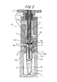
- a blow molding apparatus has a mold 1 for blow molding.
- the cavity 2 of the mold 1 has a bowl shape and opens upward on the upper surface of the mold 1.
- the mold 1 can be opened left and right, and the molded product can be taken out from the mold 1 by opening the mold 1.
- the mold 1 can be fitted with a preform PF that is blow-molded by this blow-molding device to form a casing.
- 1 and 2 show a state in which the preform PF is mounted on the mold 1.
- the preform PF is formed in a bottomed cylindrical shape as a whole by a resin material such as polypropylene (PP), for example, and a cylindrical mouth tube is formed at the upper end of the main body portion PFa having a test tube shape.
- PP polypropylene
- a portion having a shape in which the neck ring PFc is integrally provided at the lower end portion of the mouth tube portion PFb can be used while the portion PFb is integrally provided.
- the preform PF has a main body portion PFa disposed in the cavity 2 of the mold 1 along the axis thereof, and the neck ring PFc is in contact with the upper surface of the mold 1 so that the mouth tube portion PFb is formed of the mold PFb. 1 is protruded to the outside (upward in FIG. 1) and attached to the mold 1.
- a nozzle unit 10 is provided on the upper side of the mold 1 so as to be movable relative to the mold 1 in the vertical direction.
- the nozzle unit 10 has a cylindrical shape as a whole, and includes a filling head portion 11 and a support portion 21 to which the filling head portion 11 is detachably screwed in a cartridge manner.
- the filling head part 11 includes a holding member 12, a blow nozzle 13, and a supply cylinder part 14.
- the holding member 12 is formed in a block shape having a through hole penetrating in the vertical direction at the center thereof, and a cylindrical blow nozzle 13 is mounted inside the through hole.
- the mouth tube portion PFb of the preform PF attached to the mold 1 is disposed inside the through hole, and the blow nozzle 13 is fitted inside the mouth tube portion PFb.
- the neck ring PFc is sandwiched between the lower end of the holding member 12 and the upper surface of the mold 1, and the preform PF is held in a mounting posture perpendicular to the mold 1.
- a space S is defined between the outer peripheral surface of the mouth tube portion PFb of the preform PF attached to the mold 1 and the inner peripheral surface of the holding member 12.
- the supply cylinder portion 14 is configured as a cylindrical member provided with a supply path Fs extending in the vertical direction therein, and is fixed to the upper end of the holding member 12 and the mold 1 together with the holding member 12. It can be moved up and down relative to.
- An introduction port 14a that is continuous with the supply path Fs is provided on the upper end side of the supply cylinder portion 14, and a discharge port 14b that is continuous with the supply path Fs is provided on the lower end side.
- a conical seal surface 14c inclined in a reduced diameter toward the lower side is provided at the lower end of the inner surface forming the supply path Fs of the supply cylinder portion 14, and the supply axis is supplied to the shaft center of the seal surface 14c.
- a supply hole 14 d that opens the path Fs downward and communicates with the blow nozzle 13 is provided.
- the seal body 15 is formed in a short cylindrical shape, and a tapered contact surface 15a is provided on the outer peripheral edge of the lower end surface.
- the contact surface 15a has the same inclination angle as the seal surface 14c and can be in close contact with the seal surface 14c.
- An elongated cylindrical rod-like shaft body 16 is disposed along the axis of the supply path Fs inside the supply path Fs.
- the shaft body 16 penetrates the upper end of the supply cylinder portion 14 in a liquid-tight manner, and supports 21. Thus, it is supported so as to be movable in the vertical direction with respect to the filling head portion 11 and the support portion 21.
- the seal body 15 is coaxially fixed to the lower end of the shaft body 16 and is movable up and down together with the shaft body 16 inside the supply path Fs.
- the contact surface 15 a of the seal body 15 contacts the seal surface 14 c at the lower end of the supply cylinder portion 14, and the supply hole 14 d, that is, the blow nozzle 13 is closed by the seal body 15. .
- the contact surface 15a of the seal body 15 is separated from the seal surface 14c of the supply cylinder portion 14, and the supply hole 14d, that is, the blow nozzle 13 is opened.
- the shaft body 16 is hollow, and an extending rod 17 is slidably mounted on the inside thereof.
- the stretching rod 17 is movable relative to the shaft body 16 in the axial direction, and its lower end protrudes from the lower end of the seal body 15. As shown by a two-dot chain line in FIG. 2, the stretching rod 17 can stretch the preform PF in the longitudinal direction (axial direction) by moving downward.
- a guide body 18 made of polyether ether ketone (PEEK) resin having a short cylindrical shape is fixed to the lower end of the seal body 15 in order to guide the stretching rod 17.
- PEEK polyether ether ketone
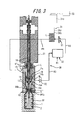
- a plunger pump 31 and a liquid circulation part 32 are connected to the nozzle unit 10.
- the plunger pump 31 includes a cylinder 31a and a plunger 31b mounted in the cylinder 31a so as to be movable in the axial direction.
- the supply cylinder portion is connected via the pipe P1.
- the pressurized liquid L can be supplied from the 14 introduction ports 14a into the supply path Fs.
- the plunger pump 31 is a servo plunger type having an electric motor 31c as a drive source, and the plunger 31b is driven by the electric motor 31c so as to operate in the axial direction in the cylinder 31a. It has become.
- a control device 33 as a control unit is connected to the electric motor 31c, and the operation of the electric motor 31c is controlled by the control device 33.
- the controller 33 can operate the electric motor 31c and change the rotation speed (the number of rotations per unit time) and the torque of the electric motor 31c to various values. That is, the control device 33 can drive the plunger 31b with an arbitrary operating speed and operating force by controlling the rotational speed and torque of the electric motor 31c.
- the control device 33 can be configured to perform a control operation in conjunction with a control system for controlling the operation of the sealing body 15 and the stretching rod 17 of the blow molding device, or the control system 33 It can also be configured as part.
- the liquid circulating unit 32 adjusts the liquid L to a predetermined temperature while replenishing the liquid L from the pipe R1, supplies the liquid L to the plunger pump 31 through the pipe R2, and also adjusts the liquid L to the predetermined temperature.
- the supply path Fs that is, the liquid L is configured as follows: supply path Fs ⁇ discharge port 14b ⁇ pipe R3 ⁇ liquid circulation unit 32 ⁇ pipe R2 ⁇ plunger pump 31 ⁇ pipe P1 ⁇ introduction port 14a ⁇ supply path Fs.
- the circulation path CR can be circulated.
- the circulation path CR is provided with two electromagnetic valves V1 and V2, and a predetermined flow path is opened and closed by the corresponding valves V1 and V2 corresponding to each process of blow molding.
- connection cylinder part 14 is provided with a connection port 14e communicating with the blow nozzle 13 through a supply hole 14d.
- a deaeration mechanism that sucks out air in the preform PF prior to blow molding, or low pressure air is instantaneously supplied into the connection port 14e and remains in the connection port 14e.
- a mechanism for discharging the liquid can be connected.
- the seal body 15 moves upward and the supply hole 14d, that is, the blow nozzle 13 is opened in a state where the plunger pump 31 is operated, the liquid pressurized from the plunger pump 31 to the blow nozzle 13 via the supply path Fs. L is supplied.
- the preform PF can be blow-molded into a shape along the cavity 2 of the mold 1.
- the control device 33 when the seal body 15 moves upward and starts its opening operation, the control device 33 operates the electric motor 31c at a predetermined rotational speed and torque so that the plunger pump 31 performs the preform. Supply of pressurized liquid L into the PF is started.
- control device 33 sets the rotational speed and torque of the electric motor 31c to lower values than before the lapse of the predetermined time after the lapse of a predetermined time since the supply of the pressurized liquid L into the preform PF is started. change. That is, the control device 33 controls the electric motor 31c to operate at a constant rotational speed and torque until a predetermined time elapses after the supply of the pressurized liquid L into the preform PF is started. Then, after a predetermined time has elapsed since the supply of the pressurized liquid L into the preform PF was started, the rotational speed and torque of the electric motor 31c are changed to lower values than before.
- control device 33 changes the rotational speed and torque of the electric motor 31c to values lower than before after a predetermined time has elapsed since the supply of the pressurized liquid L into the preform PF was started.
- the peak pressure of the liquid L supplied into the preform PF is controlled between 3.5 MPa and 5.0 MPa.
- the pressure of the liquid L supplied into the preform PF can be measured by, for example, a pressure gauge provided in the blow nozzle 13 or the supply hole 14d.
- FIG. 3 is a view showing a state where a preform is blow-molded by the blow-molding apparatus shown in FIG. 1
- FIG. 4 is a view showing a state where blow-molding by the blow-molding apparatus shown in FIG. 1 is completed.
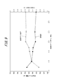
- FIG. 5 is a time chart showing the processing procedure of blow molding by the blow molding apparatus shown in FIG.
- the preform PF in which the portion excluding the mouth tube portion PFb is heated to a temperature suitable for blow molding, is mounted on the mold 1 for blow molding with the mouth tube portion PFb protruding upward and clamped. .
- the nozzle unit 10 is lowered (indicated by a three-dot chain line in FIG. 5), and the neck ring PFc is sandwiched between the holding member 12 and the upper surface of the mold 1 to hold the preform PF in the mold 1.
- the supply hole 14d is closed by the seal body 15 and the valves V1 and V2 of the circulation path CR are both opened, and the liquid L is circulated while being adjusted to a predetermined temperature by the liquid circulation section 32. It circulates through the road CR.
- FIG. 1 shows this state.
- the stretching rod 17 is moved downward (indicated by a two-dot chain line in FIG. 5), and the preform PF is moved in the longitudinal direction (axial direction) by the stretching rod 17. Stretch to.
- the valves V1 and V2 are closed to stop the circulation of the liquid L along the circulation path CR, as shown in FIG.
- the seal body 15 is moved upward together with the shaft body 16 to open the supply hole 14d, that is, the blow nozzle 13 (indicated by a one-dot chain line in FIG. 5).
- the operation of the electric motor 31c is started by the control device 33, and the plunger 31b starts to operate (shown by a broken line in FIG. 5).
- the pressurized liquid L fed from the plunger pump 31 is supplied into the preform PF through the supply hole 14d and the blow nozzle 13 (liquid supply step), and blow molding is performed.
- the control device 33 starts supplying a pressurized liquid L into the preform PF for a predetermined time (in the case of FIG. 5, about 0.5 seconds).
- a predetermined time in the case of FIG. 5, about 0.5 seconds.
- the plunger 31b is operated at a constant operating speed and operating force by operating the electric motor 31c at a constant rotational speed and torque.
- the seal body 15 is fully opened before the predetermined time has elapsed.
- control device 33 changes the rotation speed and torque of the electric motor 31c to values lower than before after a predetermined time has elapsed since the supply of the pressurized liquid L into the preform PF was started. This change is performed before the supply of the liquid L into the preform PF is completed.
- the control device 33 reduces the operating speed and operating force of the plunger 31b, and controls the supply pressure P of the liquid L supplied to the preform PF (peak pressure control step). That is, the control device 33 reduces the operating speed and the operating force of the plunger 31b after a predetermined time has elapsed since the start of the supply of the pressurized liquid L into the preform PF, thereby reducing the liquid L.
- the operating speed and operating force of the plunger pump 31, that is, the plunger 31 b are increased in the initial stage of supplying the liquid L, so that the inside of the preform PF is increased. It is possible to increase the shapeability of the preform PF by increasing the pressure of the liquid L to be supplied to the specified supply pressure P in a short time. Further, after a predetermined time has elapsed since the supply of the pressurized liquid L is started, the operating speed and operating force of the plunger 31b are reduced, and the liquid L is supplied into the preform PF at a supply pressure P lower than the initial supply.
- the pressure of the liquid L is accelerated, and the water hammer (water hammer action) is suppressed during the supply of the pressurized liquid L into the preform PF.
- the peak pressure of the liquid L supplied into the preform PF can be controlled between 3.5 MPa and 5.0 MPa.
- the liquid L is supplied into the preform PF at a supply pressure P lower than the initial supply, and a prescribed amount of the liquid L is supplied to the preform PF. Then, the operation of the plunger 31b is stopped, and this state is maintained until a predetermined holding time elapses with the seal body 15 being opened.
- the stretching rod 17 moves upward and is taken out of the preform PF, and the liquid L corresponding to the reduced amount of the stretching rod 17 taken out and removed is preformed by the operation of the plunger pump 31. Supplied in the PF.
- the filling amount of the liquid L can be adjusted by performing a suck-back process in which the plunger 31b of the plunger pump 31 is actuated in the return direction to suck the liquid L from the supply hole 14d.
- the plunger 31b is returned and the suck-back process is started 4.4 seconds after the blow molding processing procedure is started.
- the preform PF is expanded in the lateral direction (radial direction) in an expanded state by the pressure of the liquid L supplied from the plunger pump 31, and has a shape along the cavity 2 of the mold 1. It can be a skeleton.
- the seal body 15 When blow molding is completed, next, as shown in FIG. 4, the seal body 15 is lowered together with the shaft body 16 to close the supply hole 14d, that is, the blow nozzle 13, and the valves V1 and V2 are opened to circulate the liquid L again. Circulate along the road CR.
- the sealing body 15 is closed 5.5 seconds after the start of the processing procedure after the suck back process is completed. Further, after 6.4 seconds from the start of the processing procedure, the nozzle unit 10 moves up, and the mouth tube portion of the casing formed by blow-molding the preform PF is removed from the blow nozzle 13. Then, the mold 1 is opened and the casing filled with the liquid L is taken out, and the mouth tube portion is sealed with a cap or the like to complete the product containing the liquid L as the content liquid in the casing (bottle). To do.
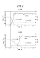
- FIG. 6 is a diagram comparing the time chart of the blow molding apparatus shown in FIG. 1 with the time chart of the blow molding apparatus of the comparative example.
- the operating speed and operating force of the plunger 31 b are changed from the start of the supply of the pressurized liquid L to the preform PF until the completion of the supply of the liquid L.
- the operating speed of the plunger 31 b is set to about one third of the operating speed of the blow molding apparatus (blow molding method) of the present invention shown in the upper time chart of FIG. 6. Therefore, the cycle of blow molding becomes long, and the manufacturing cost of the product is increased.
- the operation speed and the operation force of the plunger 31b are reduced after a predetermined time since the supply of the liquid L pressurized to the preform PF is started, and the initial supply is performed.
- the operating speed and operating force of the plunger 31b at the initial supply of the liquid L pressurized to the preform PF are increased, and the preform PF is supplied.
- the liquid supplied into the preform PF can be controlled between 3.5 MPa and 5.0 MPa. Accordingly, the preform PF can be blow-molded into a predetermined shape with high precision and stability by shortening the blow molding cycle and reducing the manufacturing cost of the product, and improving the shapeability of the preform PF. .
- the peak pressure of the liquid L is excessively increased by the water hammer phenomenon by changing the operating speed and operating force of the plunger pump 31 during the supply of the pressurized liquid L into the preform PF.
- the peak pressure of the liquid L supplied into the preform PF can be controlled between 3.5 MPa and 5.0 MPa. Therefore, while increasing the pressure of the liquid L supplied to the preform PF, the water hammer phenomenon due to the reaction can be suppressed, and the formability of the preform PF and the stability of blow molding can be improved.
- the present invention by suppressing the water hammer phenomenon as described above, the peak pressure of the liquid L is suppressed within the range of the pressure resistance of the blow molding device, and the nozzle unit 10 and the mold 1 are moved during the blow molding. It is possible to prevent a liquid leak or the like from occurring due to a gap therebetween.
- FIG. 7 is a modification of the blow molding process procedure shown in FIG. 5 and is a time chart when the holding time is shortened.
- the shaping of the preform is performed by increasing the pressure of the liquid L supplied to the preform PF while suppressing the occurrence of the water hammer phenomenon during the supply of the pressurized liquid L into the preform PF. Therefore, the retention time can be shortened as compared with the case shown in the blow molding time chart shown in FIG. Thereby, the cycle of blow molding can be further shortened, and the manufacturing cost of the product can be further increased.
- blow molding apparatus blow molding method
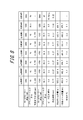
- the time from when the supply of pressurized liquid to the preform is started until the rotation speed and torque (plunger torque) of the servo motor (electric motor) are changed (time until the variable) is made different from each other.
- Three examples 1 to 3 were prepared. In the first embodiment, the time is set to 0.228 seconds, in the second embodiment, the time is set to 0.222 seconds, and in the third embodiment, the time is set to 0.241 seconds.
- the speed of the servo motor from the start of the supply of the pressurized liquid to the preform to the lapse of a predetermined time is the same at 3000 rpm, and the plunger torque is the same at 45 Nm.
- the speed of the servo motor after the lapse of a predetermined time from the start of supplying the liquid pressurized to the preform is the same at 1250 rpm, and the plunger torque is the same at 36.9 Nm. It is.
- Comparative Examples 1 to 5 were prepared as comparative examples for Examples 1 to 3. Comparative Examples 1 to 3 are shorter than Examples 1 to 3 in which the time from the start of supplying pressurized liquid to the preform until the servo motor rotation speed and plunger torque are changed is set shorter. In Comparative Example 1, the time is set to 0.205 seconds, in Comparative Example 2, the time is set to 0.180 seconds, and in Comparative Example 3, the time is set to 0.170 seconds.
- Comparative Examples 4 and 5 the speed of the servo motor and the plunger torque are kept constant from the start of the supply of the pressurized liquid to the preform until the completion of the supply of the liquid. .
- the servo motor speed is 1250 rpm and the servo motor torque (plunger torque) is 36.9 Nm.
- the servo motor speed is 3000 rpm and the servo motor torque (plunger torque). ) Is 45 Nm.
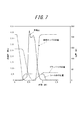
- a preform was blow-molded under the conditions of Examples 1 to 3 and Comparative Examples 1 to 5, and the peak pressure (MPa) of the liquid at that time, the bottle capacity (ml) immediately after blow molding, and 1 day after the blow molding The bottle capacity (ml) and the shrinkage (%) of the bottle capacity immediately after blow molding and one day later were compared.
- the comparison result is shown in FIG.
- Comparative Example 4 the peak pressure of the liquid at the time of blow molding is 4.0 MPa, which is the same as in Examples 1 to 3, but the pressurization time of the liquid is 1.0 second, which is about four times that of Examples 1 to 3. It becomes long. Therefore, in Comparative Example 4, compared with Examples 1 to 3, the bottle capacity immediately after blow molding is significantly reduced. As a result, in Comparative Example 4, the shrinkage rate of the bottle capacity is significantly increased to 6.1% compared to 2.3% in Examples 1 to 3. From this, it can be seen that, in Comparative Example 4, since the pressurization of the liquid is slow, the formability of the preform at the initial stage of pressurization cannot be sufficiently improved, and the blow molding of the preform is unstable. .
- Comparative Example 5 the speed of the servo motor and the plunger torque are increased compared to Comparative Example 4, so that the liquid pressurization time is 0.25 seconds, which is the same as in Examples 1 to 3.
- the peak pressure of the liquid at the time of blow molding becomes as high as 10.0 MPa or more. Therefore, in Comparative Example 5, the mold is mechanically opened at the time of blow molding, or the preform is damaged, so that blow molding cannot be completed, and the bottle capacity immediately after (bottle capacity immediately after blow molding), The bottle capacity after 1 day (bottle capacity after 1 day from blow molding) and the shrinkage rate could not be obtained.
- the control device 33 determines the operating speed and operating force of the plunger pump 31 (plunger 31b) after a predetermined time has elapsed since the start of supply of the pressurized liquid L into the preform PF.
- the value is changed to a value lower than that before the lapse of time.
- the value is not limited to this, and the operating speed and operating force of the plunger pump 31 are changed during the supply of the pressurized liquid L into the preform PF.
- the peak pressure of the liquid L supplied into the preform PF can be controlled between 3.5 MPa and 5.0 MPa, for example, the plan during the supply of the pressurized liquid L into the preform PF
- the operating speed and operating force of the jar pump 31 can be changed in multiple stages or continuously and gradually. It is also possible to change the fine actuation force.
- the plunger pump 31 is made into the servo plunger type with which the plunger 31b is driven by the electric motor 31c, it is not restricted to this,
- the operating speed and operating force of the plunger 31b are arbitrary. As long as it can be changed to the above, it can be configured to be driven by another drive mechanism such as a hydraulic cylinder or an air cylinder.
- the liquid L pressurized by opening the sealing body 15 in the middle of the longitudinal stretching by the stretching rod 17 is supplied into the preform PF, but the longitudinal stretching by the stretching rod 17 is started.
- the supply of the pressurized liquid L into the preform PF is started, or the supply of the pressurized liquid L into the preform PF is started after the longitudinal stretching by the stretching rod 17 is completed. You can also.
- the preform PF is expanded in both the longitudinal direction (axial direction) and the lateral direction (radial direction) in an expanded state only by the pressure of the liquid L supplied from the plunger pump 31 without using the stretching rod 17. It is also possible to adopt a configuration in which the casing has a shape along the cavity 2 of the mold 1.
- the preform PF a preform having a main body portion PFa and a mouth tube portion PFb but not having a neck ring PFc can be used.
- the material of the preform PF is not limited to polypropylene, but may be other resin materials.
Landscapes
- Engineering & Computer Science (AREA)
- Manufacturing & Machinery (AREA)
- Mechanical Engineering (AREA)
- Blow-Moulding Or Thermoforming Of Plastics Or The Like (AREA)
Abstract
L'invention se rapporte à un appareil de moulage par soufflage d'une préforme cylindrique ayant un fond (PF), qui est montée dans un moule de moulage par soufflage (1), en une forme qui est conforme à la cavité (2) du moule (1) par apport d'un liquide sous pression (L) à la préforme (PF), l'appareil étant pourvu : d'une buse de soufflage (13), qui s'ajuste avec l'ouverture cylindrique (PFb) de la préforme (PF) ; une pompe à piston plongeur (31) permettant d'apporter un liquide sous pression (L) à la préforme (PF) en passant par la buse de soufflage (13) ; et une unité de commande (33) permettant de maintenir la pression de crête du liquide (L) entre 3,5 MPa et 5,0 MPa pendant l'apport du liquide sous pression (L) dans la préforme par changement de la vitesse de fonctionnement et de la force de fonctionnement de la pompe à piston plongeur (31).
Priority Applications (3)
| Application Number | Priority Date | Filing Date | Title |
|---|---|---|---|
| US15/115,847 US10456973B2 (en) | 2014-01-30 | 2014-11-17 | Blow molding apparatus and blow molding method |
| EP14881196.1A EP3100844B1 (fr) | 2014-01-30 | 2014-11-17 | Appareil et procédé de moulage par soufflage |
| CN201480074588.3A CN105939832B (zh) | 2014-01-30 | 2014-11-17 | 吹塑成形装置及吹塑成形方法 |
Applications Claiming Priority (2)
| Application Number | Priority Date | Filing Date | Title |
|---|---|---|---|
| JP2014-015775 | 2014-01-30 | ||
| JP2014015775A JP6230926B2 (ja) | 2014-01-30 | 2014-01-30 | ブロー成形装置およびブロー成形方法 |
Publications (1)
| Publication Number | Publication Date |
|---|---|
| WO2015114705A1 true WO2015114705A1 (fr) | 2015-08-06 |
Family
ID=53756329
Family Applications (1)
| Application Number | Title | Priority Date | Filing Date |
|---|---|---|---|
| PCT/JP2014/005759 Ceased WO2015114705A1 (fr) | 2014-01-30 | 2014-11-17 | Appareil et procédé de moulage par soufflage |
Country Status (5)
| Country | Link |
|---|---|
| US (1) | US10456973B2 (fr) |
| EP (1) | EP3100844B1 (fr) |
| JP (1) | JP6230926B2 (fr) |
| CN (1) | CN105939832B (fr) |
| WO (1) | WO2015114705A1 (fr) |
Cited By (3)
| Publication number | Priority date | Publication date | Assignee | Title |
|---|---|---|---|---|
| WO2017087523A1 (fr) * | 2015-11-16 | 2017-05-26 | Discma Ag | Procédé pour former un récipient à l'aide d'un liquide |
| JP2018020484A (ja) * | 2016-08-03 | 2018-02-08 | 株式会社吉野工業所 | 液体ブロー成形方法 |
| WO2018042807A1 (fr) * | 2016-08-31 | 2018-03-08 | 株式会社吉野工業所 | Procédé de moulage par soufflage de liquide |
Families Citing this family (8)
| Publication number | Priority date | Publication date | Assignee | Title |
|---|---|---|---|---|
| JP6450641B2 (ja) * | 2015-04-30 | 2019-01-09 | 株式会社吉野工業所 | 液体ブロー成形装置および液体ブロー成形方法 |
| JP6685705B2 (ja) * | 2015-11-27 | 2020-04-22 | 株式会社吉野工業所 | 液体ブロー成形方法及び液体ブロー成形装置 |
| JP6605312B2 (ja) * | 2015-11-27 | 2019-11-13 | 株式会社吉野工業所 | 液体ブロー成形方法 |
| JP6629647B2 (ja) | 2016-03-11 | 2020-01-15 | 株式会社吉野工業所 | 液体ブロー成形装置及び液体ブロー成形方法 |
| JP6594823B2 (ja) * | 2016-04-28 | 2019-10-23 | 株式会社吉野工業所 | 液体ブロー成形方法 |
| JP6864570B2 (ja) | 2017-04-27 | 2021-04-28 | 株式会社吉野工業所 | 液体入り容器の製造方法 |
| JP7809027B2 (ja) * | 2022-07-29 | 2026-01-30 | 株式会社吉野工業所 | 液体充填装置 |
| DE102024112652A1 (de) * | 2024-05-06 | 2025-11-06 | Khs Gmbh | Verfahren zum Erfassen des Betriebsverhaltens einer Behälterbehandlungsanlage |
Citations (3)
| Publication number | Priority date | Publication date | Assignee | Title |
|---|---|---|---|---|
| JP2013208834A (ja) | 2012-03-30 | 2013-10-10 | Yoshino Kogyosho Co Ltd | ブロー成形装置及び合成樹脂製容器の製造方法 |
| JP2013541448A (ja) * | 2010-10-18 | 2013-11-14 | アムコー リミテッド | 液圧又は水圧ブロー成型 |
| JP2014008636A (ja) * | 2012-06-28 | 2014-01-20 | Yoshino Kogyosho Co Ltd | 容器内部の陽圧化方法及び充填容器 |
Family Cites Families (4)
| Publication number | Priority date | Publication date | Assignee | Title |
|---|---|---|---|---|
| JP2006142369A (ja) * | 2004-11-24 | 2006-06-08 | Ykk Corp | 電動式射出ユニット及び同ユニットを備えたダイキャストマシンと電動式射出方法 |
| US7914726B2 (en) * | 2006-04-13 | 2011-03-29 | Amcor Limited | Liquid or hydraulic blow molding |
| US9044887B2 (en) * | 2011-05-27 | 2015-06-02 | Discma Ag | Method of forming a container |
| WO2012170509A2 (fr) * | 2011-06-09 | 2012-12-13 | Amcor Limited | Refroidissement et pressurisation de csd pour maintenir du co2 en solution pendant le formage |
-
2014
- 2014-01-30 JP JP2014015775A patent/JP6230926B2/ja active Active
- 2014-11-17 EP EP14881196.1A patent/EP3100844B1/fr active Active
- 2014-11-17 CN CN201480074588.3A patent/CN105939832B/zh active Active
- 2014-11-17 WO PCT/JP2014/005759 patent/WO2015114705A1/fr not_active Ceased
- 2014-11-17 US US15/115,847 patent/US10456973B2/en active Active
Patent Citations (3)
| Publication number | Priority date | Publication date | Assignee | Title |
|---|---|---|---|---|
| JP2013541448A (ja) * | 2010-10-18 | 2013-11-14 | アムコー リミテッド | 液圧又は水圧ブロー成型 |
| JP2013208834A (ja) | 2012-03-30 | 2013-10-10 | Yoshino Kogyosho Co Ltd | ブロー成形装置及び合成樹脂製容器の製造方法 |
| JP2014008636A (ja) * | 2012-06-28 | 2014-01-20 | Yoshino Kogyosho Co Ltd | 容器内部の陽圧化方法及び充填容器 |
Non-Patent Citations (1)
| Title |
|---|
| See also references of EP3100844A4 |
Cited By (8)
| Publication number | Priority date | Publication date | Assignee | Title |
|---|---|---|---|---|
| WO2017087523A1 (fr) * | 2015-11-16 | 2017-05-26 | Discma Ag | Procédé pour former un récipient à l'aide d'un liquide |
| US11179874B2 (en) | 2015-11-16 | 2021-11-23 | Discma Ag | Method of forming a container using a liquid |
| JP2018020484A (ja) * | 2016-08-03 | 2018-02-08 | 株式会社吉野工業所 | 液体ブロー成形方法 |
| WO2018025494A1 (fr) * | 2016-08-03 | 2018-02-08 | 株式会社吉野工業所 | Procédé de moulage par soufflage d'un liquide |
| US10857720B2 (en) | 2016-08-03 | 2020-12-08 | Yoshino Kogyosho Co., Ltd. | Liquid blow molding method |
| WO2018042807A1 (fr) * | 2016-08-31 | 2018-03-08 | 株式会社吉野工業所 | Procédé de moulage par soufflage de liquide |
| JP2018034447A (ja) * | 2016-08-31 | 2018-03-08 | 株式会社吉野工業所 | 液体ブロー成形方法 |
| US11045992B2 (en) | 2016-08-31 | 2021-06-29 | Yoshino Kogyosho Co., Ltd. | Liquid blow molding method |
Also Published As
| Publication number | Publication date |
|---|---|
| EP3100844A4 (fr) | 2017-10-11 |
| EP3100844B1 (fr) | 2019-01-09 |
| CN105939832A (zh) | 2016-09-14 |
| US20170008216A1 (en) | 2017-01-12 |
| JP2015139988A (ja) | 2015-08-03 |
| JP6230926B2 (ja) | 2017-11-15 |
| CN105939832B (zh) | 2017-11-28 |
| EP3100844A1 (fr) | 2016-12-07 |
| US10456973B2 (en) | 2019-10-29 |
Similar Documents
| Publication | Publication Date | Title |
|---|---|---|
| JP6230926B2 (ja) | ブロー成形装置およびブロー成形方法 | |
| JP6333577B2 (ja) | ブロー成形装置 | |
| EP3450133B1 (fr) | Procédé de moulage par soufflage de liquide | |
| JP6275582B2 (ja) | ブロー成形装置 | |
| CN109641381B (zh) | 液体吹塑成型方法 | |
| JP6629647B2 (ja) | 液体ブロー成形装置及び液体ブロー成形方法 | |
| CN110545983B (zh) | 装有液体的容器的制造方法 | |
| WO2018025494A1 (fr) | Procédé de moulage par soufflage d'un liquide | |
| EP3718738B1 (fr) | Méthode de moulage par soufflage de liquide | |
| EP4296037B1 (fr) | Procédé de fabrication de récipient de liquide |
Legal Events
| Date | Code | Title | Description |
|---|---|---|---|
| 121 | Ep: the epo has been informed by wipo that ep was designated in this application |
Ref document number: 14881196 Country of ref document: EP Kind code of ref document: A1 |
|
| REEP | Request for entry into the european phase |
Ref document number: 2014881196 Country of ref document: EP |
|
| WWE | Wipo information: entry into national phase |
Ref document number: 2014881196 Country of ref document: EP |
|
| NENP | Non-entry into the national phase |
Ref country code: DE |
|
| WWE | Wipo information: entry into national phase |
Ref document number: 15115847 Country of ref document: US |