WO2015114865A1 - Afficheur à miroir - Google Patents
Afficheur à miroir Download PDFInfo
- Publication number
- WO2015114865A1 WO2015114865A1 PCT/JP2014/072709 JP2014072709W WO2015114865A1 WO 2015114865 A1 WO2015114865 A1 WO 2015114865A1 JP 2014072709 W JP2014072709 W JP 2014072709W WO 2015114865 A1 WO2015114865 A1 WO 2015114865A1
- Authority
- WO
- WIPO (PCT)
- Prior art keywords
- mirror
- display
- surface side
- display device
- auxiliary
- Prior art date
- Legal status (The legal status is an assumption and is not a legal conclusion. Google has not performed a legal analysis and makes no representation as to the accuracy of the status listed.)
- Ceased
Links
Images










Classifications
-
- G—PHYSICS
- G09—EDUCATION; CRYPTOGRAPHY; DISPLAY; ADVERTISING; SEALS
- G09G—ARRANGEMENTS OR CIRCUITS FOR CONTROL OF INDICATING DEVICES USING STATIC MEANS TO PRESENT VARIABLE INFORMATION
- G09G3/00—Control arrangements or circuits, of interest only in connection with visual indicators other than cathode-ray tubes
- G09G3/20—Control arrangements or circuits, of interest only in connection with visual indicators other than cathode-ray tubes for presentation of an assembly of a number of characters, e.g. a page, by composing the assembly by combination of individual elements arranged in a matrix no fixed position being assigned to or needed to be assigned to the individual characters or partial characters
- G09G3/34—Control arrangements or circuits, of interest only in connection with visual indicators other than cathode-ray tubes for presentation of an assembly of a number of characters, e.g. a page, by composing the assembly by combination of individual elements arranged in a matrix no fixed position being assigned to or needed to be assigned to the individual characters or partial characters by control of light from an independent source
- G09G3/3406—Control of illumination source
- G09G3/3413—Details of control of colour illumination sources
-
- G—PHYSICS
- G02—OPTICS
- G02F—OPTICAL DEVICES OR ARRANGEMENTS FOR THE CONTROL OF LIGHT BY MODIFICATION OF THE OPTICAL PROPERTIES OF THE MEDIA OF THE ELEMENTS INVOLVED THEREIN; NON-LINEAR OPTICS; FREQUENCY-CHANGING OF LIGHT; OPTICAL LOGIC ELEMENTS; OPTICAL ANALOGUE/DIGITAL CONVERTERS
- G02F1/00—Devices or arrangements for the control of the intensity, colour, phase, polarisation or direction of light arriving from an independent light source, e.g. switching, gating or modulating; Non-linear optics
- G02F1/01—Devices or arrangements for the control of the intensity, colour, phase, polarisation or direction of light arriving from an independent light source, e.g. switching, gating or modulating; Non-linear optics for the control of the intensity, phase, polarisation or colour
- G02F1/13—Devices or arrangements for the control of the intensity, colour, phase, polarisation or direction of light arriving from an independent light source, e.g. switching, gating or modulating; Non-linear optics for the control of the intensity, phase, polarisation or colour based on liquid crystals, e.g. single liquid crystal display cells
- G02F1/133—Constructional arrangements; Operation of liquid crystal cells; Circuit arrangements
- G02F1/1333—Constructional arrangements; Manufacturing methods
- G02F1/133308—Support structures for LCD panels, e.g. frames or bezels
-
- G—PHYSICS
- G02—OPTICS
- G02F—OPTICAL DEVICES OR ARRANGEMENTS FOR THE CONTROL OF LIGHT BY MODIFICATION OF THE OPTICAL PROPERTIES OF THE MEDIA OF THE ELEMENTS INVOLVED THEREIN; NON-LINEAR OPTICS; FREQUENCY-CHANGING OF LIGHT; OPTICAL LOGIC ELEMENTS; OPTICAL ANALOGUE/DIGITAL CONVERTERS
- G02F1/00—Devices or arrangements for the control of the intensity, colour, phase, polarisation or direction of light arriving from an independent light source, e.g. switching, gating or modulating; Non-linear optics
- G02F1/01—Devices or arrangements for the control of the intensity, colour, phase, polarisation or direction of light arriving from an independent light source, e.g. switching, gating or modulating; Non-linear optics for the control of the intensity, phase, polarisation or colour
- G02F1/13—Devices or arrangements for the control of the intensity, colour, phase, polarisation or direction of light arriving from an independent light source, e.g. switching, gating or modulating; Non-linear optics for the control of the intensity, phase, polarisation or colour based on liquid crystals, e.g. single liquid crystal display cells
- G02F1/133—Constructional arrangements; Operation of liquid crystal cells; Circuit arrangements
- G02F1/1333—Constructional arrangements; Manufacturing methods
- G02F1/1335—Structural association of cells with optical devices, e.g. polarisers or reflectors
- G02F1/133504—Diffusing, scattering, diffracting elements
-
- G—PHYSICS
- G02—OPTICS
- G02F—OPTICAL DEVICES OR ARRANGEMENTS FOR THE CONTROL OF LIGHT BY MODIFICATION OF THE OPTICAL PROPERTIES OF THE MEDIA OF THE ELEMENTS INVOLVED THEREIN; NON-LINEAR OPTICS; FREQUENCY-CHANGING OF LIGHT; OPTICAL LOGIC ELEMENTS; OPTICAL ANALOGUE/DIGITAL CONVERTERS
- G02F1/00—Devices or arrangements for the control of the intensity, colour, phase, polarisation or direction of light arriving from an independent light source, e.g. switching, gating or modulating; Non-linear optics
- G02F1/01—Devices or arrangements for the control of the intensity, colour, phase, polarisation or direction of light arriving from an independent light source, e.g. switching, gating or modulating; Non-linear optics for the control of the intensity, phase, polarisation or colour
- G02F1/13—Devices or arrangements for the control of the intensity, colour, phase, polarisation or direction of light arriving from an independent light source, e.g. switching, gating or modulating; Non-linear optics for the control of the intensity, phase, polarisation or colour based on liquid crystals, e.g. single liquid crystal display cells
- G02F1/133—Constructional arrangements; Operation of liquid crystal cells; Circuit arrangements
- G02F1/1333—Constructional arrangements; Manufacturing methods
- G02F1/1335—Structural association of cells with optical devices, e.g. polarisers or reflectors
- G02F1/133509—Filters, e.g. light shielding masks
- G02F1/133512—Light shielding layers, e.g. black matrix
-
- G—PHYSICS
- G02—OPTICS
- G02F—OPTICAL DEVICES OR ARRANGEMENTS FOR THE CONTROL OF LIGHT BY MODIFICATION OF THE OPTICAL PROPERTIES OF THE MEDIA OF THE ELEMENTS INVOLVED THEREIN; NON-LINEAR OPTICS; FREQUENCY-CHANGING OF LIGHT; OPTICAL LOGIC ELEMENTS; OPTICAL ANALOGUE/DIGITAL CONVERTERS
- G02F1/00—Devices or arrangements for the control of the intensity, colour, phase, polarisation or direction of light arriving from an independent light source, e.g. switching, gating or modulating; Non-linear optics
- G02F1/01—Devices or arrangements for the control of the intensity, colour, phase, polarisation or direction of light arriving from an independent light source, e.g. switching, gating or modulating; Non-linear optics for the control of the intensity, phase, polarisation or colour
- G02F1/13—Devices or arrangements for the control of the intensity, colour, phase, polarisation or direction of light arriving from an independent light source, e.g. switching, gating or modulating; Non-linear optics for the control of the intensity, phase, polarisation or colour based on liquid crystals, e.g. single liquid crystal display cells
- G02F1/133—Constructional arrangements; Operation of liquid crystal cells; Circuit arrangements
- G02F1/1333—Constructional arrangements; Manufacturing methods
- G02F1/1335—Structural association of cells with optical devices, e.g. polarisers or reflectors
- G02F1/133509—Filters, e.g. light shielding masks
- G02F1/133514—Colour filters
-
- G—PHYSICS
- G02—OPTICS
- G02F—OPTICAL DEVICES OR ARRANGEMENTS FOR THE CONTROL OF LIGHT BY MODIFICATION OF THE OPTICAL PROPERTIES OF THE MEDIA OF THE ELEMENTS INVOLVED THEREIN; NON-LINEAR OPTICS; FREQUENCY-CHANGING OF LIGHT; OPTICAL LOGIC ELEMENTS; OPTICAL ANALOGUE/DIGITAL CONVERTERS
- G02F1/00—Devices or arrangements for the control of the intensity, colour, phase, polarisation or direction of light arriving from an independent light source, e.g. switching, gating or modulating; Non-linear optics
- G02F1/01—Devices or arrangements for the control of the intensity, colour, phase, polarisation or direction of light arriving from an independent light source, e.g. switching, gating or modulating; Non-linear optics for the control of the intensity, phase, polarisation or colour
- G02F1/13—Devices or arrangements for the control of the intensity, colour, phase, polarisation or direction of light arriving from an independent light source, e.g. switching, gating or modulating; Non-linear optics for the control of the intensity, phase, polarisation or colour based on liquid crystals, e.g. single liquid crystal display cells
- G02F1/133—Constructional arrangements; Operation of liquid crystal cells; Circuit arrangements
- G02F1/1333—Constructional arrangements; Manufacturing methods
- G02F1/1335—Structural association of cells with optical devices, e.g. polarisers or reflectors
- G02F1/133528—Polarisers
- G02F1/133536—Reflective polarizers
-
- G—PHYSICS
- G02—OPTICS
- G02F—OPTICAL DEVICES OR ARRANGEMENTS FOR THE CONTROL OF LIGHT BY MODIFICATION OF THE OPTICAL PROPERTIES OF THE MEDIA OF THE ELEMENTS INVOLVED THEREIN; NON-LINEAR OPTICS; FREQUENCY-CHANGING OF LIGHT; OPTICAL LOGIC ELEMENTS; OPTICAL ANALOGUE/DIGITAL CONVERTERS
- G02F1/00—Devices or arrangements for the control of the intensity, colour, phase, polarisation or direction of light arriving from an independent light source, e.g. switching, gating or modulating; Non-linear optics
- G02F1/01—Devices or arrangements for the control of the intensity, colour, phase, polarisation or direction of light arriving from an independent light source, e.g. switching, gating or modulating; Non-linear optics for the control of the intensity, phase, polarisation or colour
- G02F1/13—Devices or arrangements for the control of the intensity, colour, phase, polarisation or direction of light arriving from an independent light source, e.g. switching, gating or modulating; Non-linear optics for the control of the intensity, phase, polarisation or colour based on liquid crystals, e.g. single liquid crystal display cells
- G02F1/133—Constructional arrangements; Operation of liquid crystal cells; Circuit arrangements
- G02F1/1333—Constructional arrangements; Manufacturing methods
- G02F1/1335—Structural association of cells with optical devices, e.g. polarisers or reflectors
- G02F1/133553—Reflecting elements
- G02F1/133555—Transflectors
-
- G—PHYSICS
- G02—OPTICS
- G02F—OPTICAL DEVICES OR ARRANGEMENTS FOR THE CONTROL OF LIGHT BY MODIFICATION OF THE OPTICAL PROPERTIES OF THE MEDIA OF THE ELEMENTS INVOLVED THEREIN; NON-LINEAR OPTICS; FREQUENCY-CHANGING OF LIGHT; OPTICAL LOGIC ELEMENTS; OPTICAL ANALOGUE/DIGITAL CONVERTERS
- G02F1/00—Devices or arrangements for the control of the intensity, colour, phase, polarisation or direction of light arriving from an independent light source, e.g. switching, gating or modulating; Non-linear optics
- G02F1/01—Devices or arrangements for the control of the intensity, colour, phase, polarisation or direction of light arriving from an independent light source, e.g. switching, gating or modulating; Non-linear optics for the control of the intensity, phase, polarisation or colour
- G02F1/13—Devices or arrangements for the control of the intensity, colour, phase, polarisation or direction of light arriving from an independent light source, e.g. switching, gating or modulating; Non-linear optics for the control of the intensity, phase, polarisation or colour based on liquid crystals, e.g. single liquid crystal display cells
- G02F1/133—Constructional arrangements; Operation of liquid crystal cells; Circuit arrangements
- G02F1/1333—Constructional arrangements; Manufacturing methods
- G02F1/1335—Structural association of cells with optical devices, e.g. polarisers or reflectors
- G02F1/1336—Illuminating devices
-
- G—PHYSICS
- G02—OPTICS
- G02F—OPTICAL DEVICES OR ARRANGEMENTS FOR THE CONTROL OF LIGHT BY MODIFICATION OF THE OPTICAL PROPERTIES OF THE MEDIA OF THE ELEMENTS INVOLVED THEREIN; NON-LINEAR OPTICS; FREQUENCY-CHANGING OF LIGHT; OPTICAL LOGIC ELEMENTS; OPTICAL ANALOGUE/DIGITAL CONVERTERS
- G02F1/00—Devices or arrangements for the control of the intensity, colour, phase, polarisation or direction of light arriving from an independent light source, e.g. switching, gating or modulating; Non-linear optics
- G02F1/01—Devices or arrangements for the control of the intensity, colour, phase, polarisation or direction of light arriving from an independent light source, e.g. switching, gating or modulating; Non-linear optics for the control of the intensity, phase, polarisation or colour
- G02F1/13—Devices or arrangements for the control of the intensity, colour, phase, polarisation or direction of light arriving from an independent light source, e.g. switching, gating or modulating; Non-linear optics for the control of the intensity, phase, polarisation or colour based on liquid crystals, e.g. single liquid crystal display cells
- G02F1/133—Constructional arrangements; Operation of liquid crystal cells; Circuit arrangements
- G02F1/1333—Constructional arrangements; Manufacturing methods
- G02F1/1335—Structural association of cells with optical devices, e.g. polarisers or reflectors
- G02F1/1336—Illuminating devices
- G02F1/133621—Illuminating devices providing coloured light
-
- G—PHYSICS
- G09—EDUCATION; CRYPTOGRAPHY; DISPLAY; ADVERTISING; SEALS
- G09G—ARRANGEMENTS OR CIRCUITS FOR CONTROL OF INDICATING DEVICES USING STATIC MEANS TO PRESENT VARIABLE INFORMATION
- G09G3/00—Control arrangements or circuits, of interest only in connection with visual indicators other than cathode-ray tubes
- G09G3/20—Control arrangements or circuits, of interest only in connection with visual indicators other than cathode-ray tubes for presentation of an assembly of a number of characters, e.g. a page, by composing the assembly by combination of individual elements arranged in a matrix no fixed position being assigned to or needed to be assigned to the individual characters or partial characters
- G09G3/34—Control arrangements or circuits, of interest only in connection with visual indicators other than cathode-ray tubes for presentation of an assembly of a number of characters, e.g. a page, by composing the assembly by combination of individual elements arranged in a matrix no fixed position being assigned to or needed to be assigned to the individual characters or partial characters by control of light from an independent source
- G09G3/36—Control arrangements or circuits, of interest only in connection with visual indicators other than cathode-ray tubes for presentation of an assembly of a number of characters, e.g. a page, by composing the assembly by combination of individual elements arranged in a matrix no fixed position being assigned to or needed to be assigned to the individual characters or partial characters by control of light from an independent source using liquid crystals
-
- G—PHYSICS
- G02—OPTICS
- G02F—OPTICAL DEVICES OR ARRANGEMENTS FOR THE CONTROL OF LIGHT BY MODIFICATION OF THE OPTICAL PROPERTIES OF THE MEDIA OF THE ELEMENTS INVOLVED THEREIN; NON-LINEAR OPTICS; FREQUENCY-CHANGING OF LIGHT; OPTICAL LOGIC ELEMENTS; OPTICAL ANALOGUE/DIGITAL CONVERTERS
- G02F1/00—Devices or arrangements for the control of the intensity, colour, phase, polarisation or direction of light arriving from an independent light source, e.g. switching, gating or modulating; Non-linear optics
- G02F1/01—Devices or arrangements for the control of the intensity, colour, phase, polarisation or direction of light arriving from an independent light source, e.g. switching, gating or modulating; Non-linear optics for the control of the intensity, phase, polarisation or colour
- G02F1/13—Devices or arrangements for the control of the intensity, colour, phase, polarisation or direction of light arriving from an independent light source, e.g. switching, gating or modulating; Non-linear optics for the control of the intensity, phase, polarisation or colour based on liquid crystals, e.g. single liquid crystal display cells
- G02F1/133—Constructional arrangements; Operation of liquid crystal cells; Circuit arrangements
- G02F1/1333—Constructional arrangements; Manufacturing methods
- G02F1/133302—Rigid substrates, e.g. inorganic substrates
-
- G—PHYSICS
- G02—OPTICS
- G02F—OPTICAL DEVICES OR ARRANGEMENTS FOR THE CONTROL OF LIGHT BY MODIFICATION OF THE OPTICAL PROPERTIES OF THE MEDIA OF THE ELEMENTS INVOLVED THEREIN; NON-LINEAR OPTICS; FREQUENCY-CHANGING OF LIGHT; OPTICAL LOGIC ELEMENTS; OPTICAL ANALOGUE/DIGITAL CONVERTERS
- G02F1/00—Devices or arrangements for the control of the intensity, colour, phase, polarisation or direction of light arriving from an independent light source, e.g. switching, gating or modulating; Non-linear optics
- G02F1/01—Devices or arrangements for the control of the intensity, colour, phase, polarisation or direction of light arriving from an independent light source, e.g. switching, gating or modulating; Non-linear optics for the control of the intensity, phase, polarisation or colour
- G02F1/13—Devices or arrangements for the control of the intensity, colour, phase, polarisation or direction of light arriving from an independent light source, e.g. switching, gating or modulating; Non-linear optics for the control of the intensity, phase, polarisation or colour based on liquid crystals, e.g. single liquid crystal display cells
- G02F1/133—Constructional arrangements; Operation of liquid crystal cells; Circuit arrangements
- G02F1/1333—Constructional arrangements; Manufacturing methods
- G02F1/1335—Structural association of cells with optical devices, e.g. polarisers or reflectors
- G02F1/133528—Polarisers
- G02F1/133548—Wire-grid polarisers
-
- G—PHYSICS
- G02—OPTICS
- G02F—OPTICAL DEVICES OR ARRANGEMENTS FOR THE CONTROL OF LIGHT BY MODIFICATION OF THE OPTICAL PROPERTIES OF THE MEDIA OF THE ELEMENTS INVOLVED THEREIN; NON-LINEAR OPTICS; FREQUENCY-CHANGING OF LIGHT; OPTICAL LOGIC ELEMENTS; OPTICAL ANALOGUE/DIGITAL CONVERTERS
- G02F1/00—Devices or arrangements for the control of the intensity, colour, phase, polarisation or direction of light arriving from an independent light source, e.g. switching, gating or modulating; Non-linear optics
- G02F1/01—Devices or arrangements for the control of the intensity, colour, phase, polarisation or direction of light arriving from an independent light source, e.g. switching, gating or modulating; Non-linear optics for the control of the intensity, phase, polarisation or colour
- G02F1/13—Devices or arrangements for the control of the intensity, colour, phase, polarisation or direction of light arriving from an independent light source, e.g. switching, gating or modulating; Non-linear optics for the control of the intensity, phase, polarisation or colour based on liquid crystals, e.g. single liquid crystal display cells
- G02F1/133—Constructional arrangements; Operation of liquid crystal cells; Circuit arrangements
- G02F1/1333—Constructional arrangements; Manufacturing methods
- G02F1/1335—Structural association of cells with optical devices, e.g. polarisers or reflectors
- G02F1/133553—Reflecting elements
- G02F1/133555—Transflectors
- G02F1/133557—Half-mirrors
-
- G—PHYSICS
- G02—OPTICS
- G02F—OPTICAL DEVICES OR ARRANGEMENTS FOR THE CONTROL OF LIGHT BY MODIFICATION OF THE OPTICAL PROPERTIES OF THE MEDIA OF THE ELEMENTS INVOLVED THEREIN; NON-LINEAR OPTICS; FREQUENCY-CHANGING OF LIGHT; OPTICAL LOGIC ELEMENTS; OPTICAL ANALOGUE/DIGITAL CONVERTERS
- G02F1/00—Devices or arrangements for the control of the intensity, colour, phase, polarisation or direction of light arriving from an independent light source, e.g. switching, gating or modulating; Non-linear optics
- G02F1/01—Devices or arrangements for the control of the intensity, colour, phase, polarisation or direction of light arriving from an independent light source, e.g. switching, gating or modulating; Non-linear optics for the control of the intensity, phase, polarisation or colour
- G02F1/13—Devices or arrangements for the control of the intensity, colour, phase, polarisation or direction of light arriving from an independent light source, e.g. switching, gating or modulating; Non-linear optics for the control of the intensity, phase, polarisation or colour based on liquid crystals, e.g. single liquid crystal display cells
- G02F1/133—Constructional arrangements; Operation of liquid crystal cells; Circuit arrangements
- G02F1/1333—Constructional arrangements; Manufacturing methods
- G02F1/1335—Structural association of cells with optical devices, e.g. polarisers or reflectors
- G02F1/13356—Structural association of cells with optical devices, e.g. polarisers or reflectors characterised by the placement of the optical elements
- G02F1/133562—Structural association of cells with optical devices, e.g. polarisers or reflectors characterised by the placement of the optical elements on the viewer side
-
- G—PHYSICS
- G02—OPTICS
- G02F—OPTICAL DEVICES OR ARRANGEMENTS FOR THE CONTROL OF LIGHT BY MODIFICATION OF THE OPTICAL PROPERTIES OF THE MEDIA OF THE ELEMENTS INVOLVED THEREIN; NON-LINEAR OPTICS; FREQUENCY-CHANGING OF LIGHT; OPTICAL LOGIC ELEMENTS; OPTICAL ANALOGUE/DIGITAL CONVERTERS
- G02F1/00—Devices or arrangements for the control of the intensity, colour, phase, polarisation or direction of light arriving from an independent light source, e.g. switching, gating or modulating; Non-linear optics
- G02F1/01—Devices or arrangements for the control of the intensity, colour, phase, polarisation or direction of light arriving from an independent light source, e.g. switching, gating or modulating; Non-linear optics for the control of the intensity, phase, polarisation or colour
- G02F1/13—Devices or arrangements for the control of the intensity, colour, phase, polarisation or direction of light arriving from an independent light source, e.g. switching, gating or modulating; Non-linear optics for the control of the intensity, phase, polarisation or colour based on liquid crystals, e.g. single liquid crystal display cells
- G02F1/133—Constructional arrangements; Operation of liquid crystal cells; Circuit arrangements
- G02F1/1333—Constructional arrangements; Manufacturing methods
- G02F1/1335—Structural association of cells with optical devices, e.g. polarisers or reflectors
- G02F1/1336—Illuminating devices
- G02F1/133602—Direct backlight
- G02F1/133603—Direct backlight with LEDs
-
- G—PHYSICS
- G02—OPTICS
- G02F—OPTICAL DEVICES OR ARRANGEMENTS FOR THE CONTROL OF LIGHT BY MODIFICATION OF THE OPTICAL PROPERTIES OF THE MEDIA OF THE ELEMENTS INVOLVED THEREIN; NON-LINEAR OPTICS; FREQUENCY-CHANGING OF LIGHT; OPTICAL LOGIC ELEMENTS; OPTICAL ANALOGUE/DIGITAL CONVERTERS
- G02F1/00—Devices or arrangements for the control of the intensity, colour, phase, polarisation or direction of light arriving from an independent light source, e.g. switching, gating or modulating; Non-linear optics
- G02F1/01—Devices or arrangements for the control of the intensity, colour, phase, polarisation or direction of light arriving from an independent light source, e.g. switching, gating or modulating; Non-linear optics for the control of the intensity, phase, polarisation or colour
- G02F1/13—Devices or arrangements for the control of the intensity, colour, phase, polarisation or direction of light arriving from an independent light source, e.g. switching, gating or modulating; Non-linear optics for the control of the intensity, phase, polarisation or colour based on liquid crystals, e.g. single liquid crystal display cells
- G02F1/133—Constructional arrangements; Operation of liquid crystal cells; Circuit arrangements
- G02F1/1333—Constructional arrangements; Manufacturing methods
- G02F1/1335—Structural association of cells with optical devices, e.g. polarisers or reflectors
- G02F1/1336—Illuminating devices
- G02F1/133616—Front illuminating devices
-
- G—PHYSICS
- G02—OPTICS
- G02F—OPTICAL DEVICES OR ARRANGEMENTS FOR THE CONTROL OF LIGHT BY MODIFICATION OF THE OPTICAL PROPERTIES OF THE MEDIA OF THE ELEMENTS INVOLVED THEREIN; NON-LINEAR OPTICS; FREQUENCY-CHANGING OF LIGHT; OPTICAL LOGIC ELEMENTS; OPTICAL ANALOGUE/DIGITAL CONVERTERS
- G02F1/00—Devices or arrangements for the control of the intensity, colour, phase, polarisation or direction of light arriving from an independent light source, e.g. switching, gating or modulating; Non-linear optics
- G02F1/01—Devices or arrangements for the control of the intensity, colour, phase, polarisation or direction of light arriving from an independent light source, e.g. switching, gating or modulating; Non-linear optics for the control of the intensity, phase, polarisation or colour
- G02F1/13—Devices or arrangements for the control of the intensity, colour, phase, polarisation or direction of light arriving from an independent light source, e.g. switching, gating or modulating; Non-linear optics for the control of the intensity, phase, polarisation or colour based on liquid crystals, e.g. single liquid crystal display cells
- G02F1/133—Constructional arrangements; Operation of liquid crystal cells; Circuit arrangements
- G02F1/1333—Constructional arrangements; Manufacturing methods
- G02F1/1335—Structural association of cells with optical devices, e.g. polarisers or reflectors
- G02F1/1336—Illuminating devices
- G02F1/133626—Illuminating devices providing two modes of illumination, e.g. day-night
-
- G—PHYSICS
- G02—OPTICS
- G02F—OPTICAL DEVICES OR ARRANGEMENTS FOR THE CONTROL OF LIGHT BY MODIFICATION OF THE OPTICAL PROPERTIES OF THE MEDIA OF THE ELEMENTS INVOLVED THEREIN; NON-LINEAR OPTICS; FREQUENCY-CHANGING OF LIGHT; OPTICAL LOGIC ELEMENTS; OPTICAL ANALOGUE/DIGITAL CONVERTERS
- G02F1/00—Devices or arrangements for the control of the intensity, colour, phase, polarisation or direction of light arriving from an independent light source, e.g. switching, gating or modulating; Non-linear optics
- G02F1/01—Devices or arrangements for the control of the intensity, colour, phase, polarisation or direction of light arriving from an independent light source, e.g. switching, gating or modulating; Non-linear optics for the control of the intensity, phase, polarisation or colour
- G02F1/13—Devices or arrangements for the control of the intensity, colour, phase, polarisation or direction of light arriving from an independent light source, e.g. switching, gating or modulating; Non-linear optics for the control of the intensity, phase, polarisation or colour based on liquid crystals, e.g. single liquid crystal display cells
- G02F1/133—Constructional arrangements; Operation of liquid crystal cells; Circuit arrangements
- G02F1/1333—Constructional arrangements; Manufacturing methods
- G02F1/1335—Structural association of cells with optical devices, e.g. polarisers or reflectors
- G02F1/13363—Birefringent elements, e.g. for optical compensation
-
- G—PHYSICS
- G02—OPTICS
- G02F—OPTICAL DEVICES OR ARRANGEMENTS FOR THE CONTROL OF LIGHT BY MODIFICATION OF THE OPTICAL PROPERTIES OF THE MEDIA OF THE ELEMENTS INVOLVED THEREIN; NON-LINEAR OPTICS; FREQUENCY-CHANGING OF LIGHT; OPTICAL LOGIC ELEMENTS; OPTICAL ANALOGUE/DIGITAL CONVERTERS
- G02F1/00—Devices or arrangements for the control of the intensity, colour, phase, polarisation or direction of light arriving from an independent light source, e.g. switching, gating or modulating; Non-linear optics
- G02F1/01—Devices or arrangements for the control of the intensity, colour, phase, polarisation or direction of light arriving from an independent light source, e.g. switching, gating or modulating; Non-linear optics for the control of the intensity, phase, polarisation or colour
- G02F1/13—Devices or arrangements for the control of the intensity, colour, phase, polarisation or direction of light arriving from an independent light source, e.g. switching, gating or modulating; Non-linear optics for the control of the intensity, phase, polarisation or colour based on liquid crystals, e.g. single liquid crystal display cells
- G02F1/133—Constructional arrangements; Operation of liquid crystal cells; Circuit arrangements
- G02F1/1333—Constructional arrangements; Manufacturing methods
- G02F1/1335—Structural association of cells with optical devices, e.g. polarisers or reflectors
- G02F1/13363—Birefringent elements, e.g. for optical compensation
- G02F1/133638—Waveplates, i.e. plates with a retardation value of lambda/n
-
- G—PHYSICS
- G02—OPTICS
- G02F—OPTICAL DEVICES OR ARRANGEMENTS FOR THE CONTROL OF LIGHT BY MODIFICATION OF THE OPTICAL PROPERTIES OF THE MEDIA OF THE ELEMENTS INVOLVED THEREIN; NON-LINEAR OPTICS; FREQUENCY-CHANGING OF LIGHT; OPTICAL LOGIC ELEMENTS; OPTICAL ANALOGUE/DIGITAL CONVERTERS
- G02F1/00—Devices or arrangements for the control of the intensity, colour, phase, polarisation or direction of light arriving from an independent light source, e.g. switching, gating or modulating; Non-linear optics
- G02F1/01—Devices or arrangements for the control of the intensity, colour, phase, polarisation or direction of light arriving from an independent light source, e.g. switching, gating or modulating; Non-linear optics for the control of the intensity, phase, polarisation or colour
- G02F1/13—Devices or arrangements for the control of the intensity, colour, phase, polarisation or direction of light arriving from an independent light source, e.g. switching, gating or modulating; Non-linear optics for the control of the intensity, phase, polarisation or colour based on liquid crystals, e.g. single liquid crystal display cells
- G02F1/133—Constructional arrangements; Operation of liquid crystal cells; Circuit arrangements
- G02F1/136—Liquid crystal cells structurally associated with a semi-conducting layer or substrate, e.g. cells forming part of an integrated circuit
- G02F1/1362—Active matrix addressed cells
- G02F1/1368—Active matrix addressed cells in which the switching element is a three-electrode device
-
- G—PHYSICS
- G02—OPTICS
- G02F—OPTICAL DEVICES OR ARRANGEMENTS FOR THE CONTROL OF LIGHT BY MODIFICATION OF THE OPTICAL PROPERTIES OF THE MEDIA OF THE ELEMENTS INVOLVED THEREIN; NON-LINEAR OPTICS; FREQUENCY-CHANGING OF LIGHT; OPTICAL LOGIC ELEMENTS; OPTICAL ANALOGUE/DIGITAL CONVERTERS
- G02F2413/00—Indexing scheme related to G02F1/13363, i.e. to birefringent elements, e.g. for optical compensation, characterised by the number, position, orientation or value of the compensation plates
- G02F2413/01—Number of plates being 1
-
- G—PHYSICS
- G02—OPTICS
- G02F—OPTICAL DEVICES OR ARRANGEMENTS FOR THE CONTROL OF LIGHT BY MODIFICATION OF THE OPTICAL PROPERTIES OF THE MEDIA OF THE ELEMENTS INVOLVED THEREIN; NON-LINEAR OPTICS; FREQUENCY-CHANGING OF LIGHT; OPTICAL LOGIC ELEMENTS; OPTICAL ANALOGUE/DIGITAL CONVERTERS
- G02F2413/00—Indexing scheme related to G02F1/13363, i.e. to birefringent elements, e.g. for optical compensation, characterised by the number, position, orientation or value of the compensation plates
- G02F2413/05—Single plate on one side of the LC cell
-
- G—PHYSICS
- G09—EDUCATION; CRYPTOGRAPHY; DISPLAY; ADVERTISING; SEALS
- G09G—ARRANGEMENTS OR CIRCUITS FOR CONTROL OF INDICATING DEVICES USING STATIC MEANS TO PRESENT VARIABLE INFORMATION
- G09G2300/00—Aspects of the constitution of display devices
- G09G2300/04—Structural and physical details of display devices
-
- G—PHYSICS
- G09—EDUCATION; CRYPTOGRAPHY; DISPLAY; ADVERTISING; SEALS
- G09G—ARRANGEMENTS OR CIRCUITS FOR CONTROL OF INDICATING DEVICES USING STATIC MEANS TO PRESENT VARIABLE INFORMATION
- G09G2320/00—Control of display operating conditions
- G09G2320/06—Adjustment of display parameters
- G09G2320/0626—Adjustment of display parameters for control of overall brightness
-
- G—PHYSICS
- G09—EDUCATION; CRYPTOGRAPHY; DISPLAY; ADVERTISING; SEALS
- G09G—ARRANGEMENTS OR CIRCUITS FOR CONTROL OF INDICATING DEVICES USING STATIC MEANS TO PRESENT VARIABLE INFORMATION
- G09G2320/00—Control of display operating conditions
- G09G2320/06—Adjustment of display parameters
- G09G2320/0666—Adjustment of display parameters for control of colour parameters, e.g. colour temperature
-
- G—PHYSICS
- G09—EDUCATION; CRYPTOGRAPHY; DISPLAY; ADVERTISING; SEALS
- G09G—ARRANGEMENTS OR CIRCUITS FOR CONTROL OF INDICATING DEVICES USING STATIC MEANS TO PRESENT VARIABLE INFORMATION
- G09G2360/00—Aspects of the architecture of display systems
- G09G2360/14—Detecting light within display terminals, e.g. using a single or a plurality of photosensors
- G09G2360/144—Detecting light within display terminals, e.g. using a single or a plurality of photosensors the light being ambient light
-
- G—PHYSICS
- G09—EDUCATION; CRYPTOGRAPHY; DISPLAY; ADVERTISING; SEALS
- G09G—ARRANGEMENTS OR CIRCUITS FOR CONTROL OF INDICATING DEVICES USING STATIC MEANS TO PRESENT VARIABLE INFORMATION
- G09G2360/00—Aspects of the architecture of display systems
- G09G2360/14—Detecting light within display terminals, e.g. using a single or a plurality of photosensors
- G09G2360/145—Detecting light within display terminals, e.g. using a single or a plurality of photosensors the light originating from the display screen
Definitions
- the present invention relates to a mirror display. More specifically, the present invention relates to a mirror display that achieves both a mirror mode that functions as a mirror and a display mode that displays an image.
- the mirror display can be used as a mirror in addition to the display that is the original purpose. That is, in the mirror display, when display light is emitted from the display device and in an area where the display light is emitted from the display device, image display is performed using the display light, while display light is emitted from the display device. It is used as a mirror by reflecting external light when it is not emitted and in a region where display light is not emitted from the display device.
- a metal vapor deposition film, a dielectric multilayer film, and the like are known.
- a mirror display using a reflective polarizing plate as a half mirror layer has been proposed as one that can further improve the visibility of an image in a bright place in the display mode (see, for example, Patent Document 2).
- the reflective polarizing plate a multilayer reflective polarizing plate, a reflective polarizing plate combining a cholesteric liquid crystal and a ⁇ / 4 plate, a wire grid reflective polarizing plate, and the like are known.
- the multilayer reflective polarizing plate include a reflective polarizing plate (trade name: DBEF) manufactured by Sumitomo 3M Limited.
- An example of a reflective polarizing plate that combines a cholesteric liquid crystal and a ⁇ / 4 plate is a reflective polarizing plate (trade name: NIPOCS) manufactured by Nitto Denko Corporation.
- the mirror display functions as a mirror by reflecting external light, it is difficult to obtain sufficient visibility when used as a mirror in a dark place.
- a mirror display using a reflective polarizing plate as a half mirror layer due to the principle of functioning as a mirror, it is not possible to make the reflectance in the mirror mode equal to or higher than that of a normal mirror. It was difficult. For this reason, such a mirror display is required to improve the visibility of the reflected image in the mirror mode, and particularly has a problem that the visibility of the reflected image in a dark place is poor.
- a mirror display including an auxiliary illumination unit for illuminating an object (for example, an observer's face) in the mirror mode has been proposed (see, for example, Patent Documents 3 to 5).
- Japanese Patent No. 4664534 Japanese Patent No. 4211341 JP 2004-184491 A JP 2005-321717 A JP 2004-212782 A
- the auxiliary lighting unit is visually recognized.
- the design may be deteriorated.
- the luminance of the auxiliary lighting unit is not sufficient, and the visibility in the dark place in the mirror mode may not be sufficiently improved.
- auxiliary lighting unit In order to improve visibility in a dark place in the mirror mode, for example, it is conceivable to use a separate desk lamp as an auxiliary lighting unit. However, in such a case, it is necessary to secure the installation location and power supply of the auxiliary lighting unit separately from the mirror display, and the auxiliary lighting unit is easy to be visually recognized, so the product value such as convenience and design is reduced. There was a problem.
- Patent Document 3 discloses that a display device capable of realizing both the display mode and the mirror mode can recognize a bright mirror image even in a dark environment.
- the invention described in Patent Document 3 there is room for improvement in terms of improving the design because the auxiliary illumination unit is disposed on the outside from the edge of the half mirror plate and is easily visible.
- Patent Document 4 discloses that a display device that can use a mirror function even in a dark surrounding environment is provided.
- the invention described in Patent Document 4 like the invention described in Patent Document 3, since the auxiliary lighting unit is easily visually recognized, there is room for improvement in terms of improving design.
- Patent Document 5 discloses that in a display device that can be executed by switching between the display mode and the mirror mode, the display quality is improved and the entire display device is reduced in thickness and weight.
- the auxiliary illumination unit since the auxiliary illumination unit uses display light at the time of white display of the display device, the luminance of light emitted from the auxiliary illumination unit to the observation surface side is the mirror display. When the brightness is measured, it does not become higher than the brightness when the display device displays white. Therefore, there is room for improvement in terms of sufficiently improving the visibility in the dark place in the mirror mode.
- the present invention has been made in view of the above situation, and an object thereof is to provide a mirror display that can sufficiently improve the visibility in a dark place in the mirror mode while improving the design. Is.
- the present inventors have made various studies on a mirror display that can improve the visibility in a dark place in the mirror mode while improving the design, and (1) the light source in the auxiliary lighting unit is visually recognized.
- one embodiment of the present invention is a mirror display including a half mirror plate having a half mirror layer, a display device, a housing, and an auxiliary lighting unit including an auxiliary light source
- the housing includes at least the half mirror.
- An outer frame portion that holds the plate and the display device and covers the front surface of the end portion of the half mirror plate when viewed in plan from the observation surface side
- the display device includes a rear surface of the half mirror plate
- the auxiliary light source is arranged on the back side of the half mirror plate, the display device, or the outer frame portion, the display light is emitted from the display device, and the display light is emitted from the half mirror plate. Can be switched between a display mode that transmits light and a mirror mode that does not emit display light from the display device.
- the bright unit is controlled separately from the display device and emits light to the observation surface side in the mirror mode, and the luminance of the light emitted from the auxiliary illumination unit is measured on the observation surface side of the mirror display
- it may be a mirror display (hereinafter also referred to as a first mirror display of the present invention) that is higher in luminance than the white display time of the display device.
- Another embodiment of the present invention is a mirror display including a half mirror plate having a half mirror layer and a display device, wherein display light is emitted from the display device, and the display light is emitted from the half mirror plate.
- a mirror display that includes an auxiliary illumination unit that emits light to the display, and the luminance of the light emitted from the auxiliary illumination unit is higher than the luminance during white display of the display device when measured on the observation surface side of the mirror display (Hereinafter also referred to as a second mirror display of the present invention).
- the mirror display which can fully improve the visibility in the dark place at the time of mirror mode can be provided, improving design property.
- FIG. 1 is a schematic plan view showing a mirror display of Example 1.
- FIG. 2 is a schematic cross-sectional view showing a cross section of a portion corresponding to a line segment A-A ′ in FIG. 1.
- assistant illumination unit in FIG. 6 is a schematic plan view showing a mirror display of Example 2.
- FIG. 5 is a schematic cross-sectional view showing a cross section of a portion corresponding to a line segment B-B ′ in FIG. 4. It is explanatory drawing which expanded the auxiliary
- FIG. FIG. 1 is a schematic plan view showing a mirror display of Example 1.
- FIG. 2 is a schematic cross-sectional view showing a cross section of a portion corresponding to a line segment A-A ′ in FIG. 1.
- assistant illumination unit in FIG. 6 is a schematic plan view showing a mirror
- FIG. 8 is a schematic cross-sectional view showing a cross section of a portion corresponding to a line segment C-C ′ in FIG. 7. It is explanatory drawing which expanded the auxiliary
- FIG. 11 is a schematic cross-sectional view showing a cross section of a portion corresponding to a line segment D-D ′ in FIG. 10.
- 10 is a schematic plan view showing a mirror display of Example 5.
- FIG. 13 is a schematic cross-sectional view showing a cross section of a portion corresponding to a line segment E-E ′ in FIG. 12.
- 10 is a schematic plan view showing a mirror display of Example 6.
- FIG. FIG. 11 is a schematic cross-sectional view showing a cross section of a portion corresponding to a line segment D-D ′ in FIG. 10.
- 10 is a schematic plan view showing a mirror display of Example 5.
- FIG. 13 is a schematic cross-sectional view
- FIG. 15 is a schematic cross-sectional view showing a cross section of a portion corresponding to a line segment F-F ′ in FIG. 14.
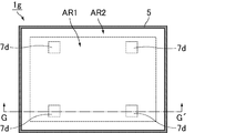
- FIG. 10 is a schematic plan view showing a mirror display of Example 7.
- FIG. 17 is a schematic cross-sectional view showing a cross section of a portion corresponding to a line segment G-G ′ in FIG. 16.
- FIG. 10 is a schematic plan view showing a mirror display of Example 8.
- FIG. 19 is a schematic cross-sectional view showing a cross section of a portion corresponding to a line segment H-H ′ in FIG. 18.
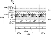
- 10 is a schematic cross-sectional view showing a mirror display of Example 9.
- FIG. 10 is a schematic cross-sectional view showing a mirror display of Example 10.
- FIG. 10 is a schematic cross-sectional view showing a mirror display of Example 11.
- FIG. FIG. 16 is a schematic cross-sectional view showing a mirror display of Example 12. It is a cross-sectional schematic diagram which shows the mirror display of Example 13. It is a cross-sectional schematic diagram which shows the mirror display of Example 14.
- 16 is a schematic cross-sectional view showing a mirror display of Example 15.
- FIG. 16 is a schematic cross-sectional view showing a mirror display of Example 16.
- FIG. 18 is a schematic cross-sectional view showing a mirror display of Example 17.
- FIG. 31 is a schematic cross-sectional view showing a cross section of a portion corresponding to a line segment a-a ′ in FIG. 30.
- 10 is a schematic cross-sectional view showing a mirror display of Comparative Example 2.
- FIG. It is a cross-sectional schematic diagram which shows the mirror display of the comparative example 3.
- the type of the display device is not particularly limited.
- a plasma display device an organic electroluminescence display device, an inorganic electroluminescence display device, etc. It can also be used.
- Example 1 relates to the first mirror display of the present invention, in which the auxiliary lighting unit includes an auxiliary light source and a light guide plate arranged on the back side of the outer frame portion.
- the present invention also relates to a configuration in which the size of the liquid crystal display device is the same size as that of the half mirror plate when viewed in plan from the observation surface side.
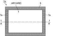
- FIG. 1 is a schematic plan view illustrating a mirror display according to the first embodiment.
- a region surrounded by the housing 5 includes a display region AR1 that functions as an image display surface in the display mode and a mirror that functions as a mirror surface in the mirror mode.
- Area AR2 is arranged.
- the display area AR1 and the mirror area AR2 have the same size.
- the auxiliary illumination unit 7a is disposed along the back side of the housing 5 and along two opposing sides of the display area AR1 (mirror area AR2).
- the auxiliary lighting units 7a are arranged at two places, but may be arranged at one place or three or more places. Further, the arrangement location of the auxiliary illumination unit 7a is not limited to the positions along the two opposite left and right sides of the display area AR1 (mirror area AR2), and may be any position along the four upper, lower, left and right sides. Good.
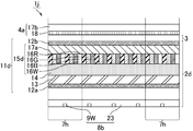
- FIG. 2 is a schematic cross-sectional view showing a cross section of a portion corresponding to the line segment A-A ′ in FIG.
- the mirror display 1a includes a liquid crystal display device 2a, an air layer 3, and a half mirror plate 4a in order from the back surface side to the observation surface side.
- the mirror display 1a further includes a housing 5 that holds the liquid crystal display device 2a and the half mirror plate 4a, and an auxiliary illumination unit 7a that is disposed at a position corresponding to FIG. 1 on the outer periphery of the half mirror plate 4a. Yes.
- the size of the liquid crystal display device 2a was the same as that of the half mirror plate 4a when viewed in plan from the observation surface side.
- the liquid crystal display device 2a and the half mirror plate 4a were fixed by fitting the upper end and the lower end of the half mirror plate 4a into a pair of aluminum rails attached in a frame shape to the upper end and the lower end of the liquid crystal display device 2a.
- the air layer 3 is a space formed in a slight gap between the liquid crystal display device 2a and the half mirror plate 4a.
- the “observation surface” indicates the surface of the mirror display on the half mirror plate side
- the “observation surface side” indicates the upper side of the mirror display 1a in FIG.
- the “rear surface” indicates a surface opposite to the observation surface of the mirror display
- the “rear surface” indicates the lower side of the mirror display 1a in FIG.
- the “front surface” indicates a surface on the observation surface side.
- the liquid crystal display device 2a includes a backlight unit 8a and a liquid crystal display panel 11a in order from the back side to the observation surface side.
- the backlight unit 8a includes a light guide plate 10a, and a white light emitting diode (LED) 9W as a display light source disposed adjacent to the end of the light guide plate 10a, and is an edge light type. Is adopted.
- a white light emitting diode (LED) 9W as a display light source disposed adjacent to the end of the light guide plate 10a, and is an edge light type. Is adopted.
- the light guide plate 10a an acrylic resin was used.
- As the LED 9W an LED backlight unit mounted on a Sharp liquid crystal television (LC-20F5-B) was used.
- the liquid crystal display panel 11a has an absorption polarizing plate 12a, a thin film transistor array substrate 13, a liquid crystal layer 14, a color filter substrate 15a, and an absorption polarizing plate 12b in order from the back side to the observation surface side.
- the display mode of the liquid crystal display panel 11a was set to a VA (Vertical Alignment) mode.
- the display mode of the liquid crystal display panel 11a is not particularly limited, and for example, a TN (Twisted Nematic) mode, an IPS (In-Plane Switching) mode, an FFS (Fringe Field Switching) mode, or the like may be employed.
- the display area is preferably a black display screen, and from the viewpoint of low power consumption, the voltage to the liquid crystal display device is preferably not applied in the mirror mode.
- a normally black display mode (for example, VA mode, IPS mode, FFS mode, etc.) that shows a black display screen at the time of addition is preferable.
- the driving method of the liquid crystal display panel 11a was active matrix driving.
- the driving method of the liquid crystal display panel 11a is not particularly limited, and static driving, simple matrix driving, or the like may be employed.
- the thin film transistor array substrate 13 has a configuration in which various wirings (not shown) such as thin film transistor elements are arranged on a glass substrate.
- a transparent substrate such as a plastic substrate may be used instead of the glass substrate.
- As a structure of the semiconductor layer included in the thin film transistor element amorphous silicon was used.
- the configuration of the semiconductor layer is not particularly limited, and may include low-temperature polysilicon, an oxide semiconductor, or the like.
- Examples of the structure of the oxide semiconductor include a compound composed of indium, gallium, zinc, and oxygen, a compound composed of indium, zinc, and oxygen.
- the off-leakage current is small. Therefore, when a voltage is applied, the voltage application state is maintained until the next data is written. Is possible. Therefore, from the viewpoint of low power consumption, it is preferable to use a compound including indium, gallium, zinc, and oxygen as the oxide semiconductor.
- the color filter substrate 15a includes a glass substrate 17a and color filter layers 16R (red), 16G (green), and 16B (blue) disposed on the thin film transistor array substrate 13 side of the glass substrate 17a.
- a transparent substrate such as a plastic substrate may be used instead of the glass substrate 17a.
- the color combination of the color filter layer is not particularly limited, and may be a combination of red, green, blue, and yellow, for example.
- the liquid crystal layer 14 is sandwiched between the thin film transistor array substrate 13 and the color filter substrate 15a, and the thin film transistor array substrate 13 and the color filter substrate 15a are bonded to each other through a sealing material (not shown). .
- the absorption polarizing plate 12a was bonded to the back side of the thin film transistor array substrate 13 via an adhesive (not shown).
- the absorption polarizing plate 12b was bonded to the observation surface side of the color filter substrate 15a via an adhesive (not shown).
- the absorption polarizing plates 12a and 12b were arranged so that their absorption axes were orthogonal to each other.
- the half mirror plate 4a includes a reflective polarizing plate 18 as a half mirror layer and a glass substrate 17b as a base material for holding the half mirror layer in order from the back side to the observation surface side.
- the reflective polarizing plate 18 and the glass substrate 17b were bonded together via an adhesive (not shown).
- the reflection-type polarizing plate 18 and the absorption-type polarizing plate 12b were arranged so that their transmission axes were parallel to each other.
- the reflective polarizing plate 18 a multilayer reflective polarizing plate (trade name: DBEF) manufactured by Sumitomo 3M Limited was used.
- DBEF multilayer reflective polarizing plate
- a reflective polarizing plate combining a cholesteric liquid crystal and a ⁇ / 4 plate, a wire grid reflective polarizing plate, or the like may be used.
- An example of a reflective polarizing plate that combines a cholesteric liquid crystal and a ⁇ / 4 plate is a reflective polarizing plate (trade name: NIPOCS) manufactured by Nitto Denko Corporation.
- the half mirror layer is not particularly limited as long as it has a beam splitter function of reflecting a part of incident light and transmitting a part thereof.
- a metal vapor deposition film, a dielectric multilayer film Etc. may be used.
- the mirror display preferably has a combination of a liquid crystal display device and a reflective polarizing plate.
- the reflective polarizing plate is more preferable than the dielectric multilayer film.
- the reflectance (luminous reflectance) and transmittance of the half mirror layer are not particularly limited.
- the thickness of the metal vapor deposition film or the dielectric multilayer film can be increased or decreased, and two or more reflective polarizing plates can be connected to each other. Arbitrary adjustments can be made by laminating layers and combining two or more half mirror layers.
- the half mirror layer may have an infrared absorption function or an ultraviolet absorption function in addition to the beam splitter function.
- the glass substrate 17b soda lime glass was used as the material, and the thickness was 3.2 mm.
- quartz glass, non-alkali glass, borosilicate glass, or the like may be used.
- the substrate for holding the half mirror layer is not particularly limited as long as it is highly transparent.
- a resin plastic substrate such as (resin) may be used. From the viewpoint of improving the flatness and rigidity of the half mirror plate, it is preferable to use a glass substrate as the base material.
- the thickness of the substrate is not particularly limited, and can be selected depending on the application in consideration of weight, strength, size, and the like.
- the size of the glass substrate 17b is not particularly limited as long as it is the same size as the liquid crystal display device 2a when viewed in plan from the observation surface side, as long as it is larger than the display area and smaller than the casing 5. .
- size of the glass substrate 17b can be arbitrarily selected by the fixing method etc. of a half mirror layer.
- the casing 5 a black plastic resin having a light shielding property was used.
- the material of the housing 5 is not particularly limited as long as it has light shielding properties, and a metal material such as iron or aluminum may be used.
- the housing 5 includes an outer frame portion 6 that covers the front surface of the end portion of the half mirror plate 4a.
- the auxiliary lighting unit 7a includes a light guide plate 10b and a white LED 9W 'as an auxiliary light source.
- the light guide plate 10 b is disposed on the back side of the outer frame portion 6.
- the LED 9W ' is disposed on the back side of the outer frame portion 6 and adjacent to the end portion of the light guide plate 10b. Therefore, according to the mirror display of the first embodiment, the LED 9W 'becomes difficult to be visually recognized from the observation surface side, so that the design can be improved.
- FIG. 2 a state in which one LED 9 ⁇ / b> W ′ is disposed adjacent to the end of the light guide plate 10 b is shown, but in reality, when viewed in plan from the observation surface side, the five LEDs are equally spaced. Has been placed.
- the LED 9W ' an LED chip (trade name: NSCW008AT) manufactured by Nichia Corporation was used.
- the auxiliary light source is not particularly limited as long as the luminance of light emitted to the observation surface side is higher than the luminance during white display of the liquid crystal display device when measured on the observation surface side of the mirror display.
- a fluorescent lamp, an organic electroluminescence element, an inorganic electroluminescence element, or the like may be used.
- the LED 9W ' is controlled separately from the LED 9W. In the display mode, the LED 9W' is not turned on, and thus does not hinder image display.
- the light guide plate 10b is made of acrylic resin and has a thickness of 3 mm.
- An AG (anti-glare, anti-glare) film 19 for scattering light was bonded to the surface corresponding to the cut portion.
- the thickness of the light guide plate 10b is not particularly limited, it is preferably 5 mm or less and preferably 3 mm or less from the viewpoint of improving the design by reducing the distance between the half mirror plate 4 a and the outer frame portion 6. More preferred.
- the distance between the screen surface and the housing is often about 5 mm. Therefore, by setting the thickness of the light guide plate 10b to 5 mm or less, a mirror display can be manufactured without changing anything other than the housing, which is advantageous in terms of manufacturing cost.
- the auxiliary illumination unit 7a can emit light to the observation surface side in the mirror mode based on the principle shown in FIG.
- FIG. 3 is an explanatory diagram in which the auxiliary lighting unit in FIG. 2 is enlarged.
- the light emitted from the LED 9 ⁇ / b> W ′ in the mirror mode is repeatedly reflected on the surface in the light guide plate 10 b and then emitted to the outside through the AG film 19. Thereafter, the light emitted from the AG film 19 is reflected by the surface of the half mirror plate 4a and emitted to the observation surface side.
- the auxiliary illumination unit 7a is disposed closer to the observation surface than the liquid crystal display device 2a, it is not necessary to consider light transmission loss in the liquid crystal display device 2a, and the white color of the liquid crystal display device 2a is not necessary. It is possible to illuminate the object with light having higher brightness than that at the time of display. Therefore, according to the mirror display of Example 1, the visibility in the dark place at the time of mirror mode can fully be improved.
- Example 2 relates to the first mirror display of the present invention, in which the auxiliary lighting unit includes an auxiliary light source and a light guide plate arranged on the back side of the outer frame, and the difference from Example 1 is The size of the light guide plate. Since the mirror display of Example 2 is the same as the mirror display of Example 1 except these structures, description is abbreviate
- FIG. 4 is a schematic plan view showing the mirror display of the second embodiment.
- the display area AR1 and the mirror area AR2 having the same size are arranged in the area surrounded by the casing 5.
- the auxiliary lighting unit 7b is arranged along the back side of the housing 5 and along two opposing sides of the display area AR1 (mirror area AR2).
- the auxiliary lighting unit 7b is arranged at two places, but may be arranged at one place or three or more places.
- the arrangement location of the auxiliary illumination unit 7b is not limited to the positions along the two opposite left and right sides of the display area AR1 (mirror area AR2), and may be any position along the four upper, lower, left and right sides. Good.
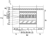
- FIG. 5 is a schematic cross-sectional view showing a cross section of a portion corresponding to the line segment B-B ′ in FIG. 4.
- the mirror display 1b includes a liquid crystal display device 2a, an air layer 3, and a half mirror plate 4a in order from the back side to the observation surface side.
- the mirror display 1b further includes a housing 5 that holds the liquid crystal display device 2a and the half mirror plate 4a, and an auxiliary illumination unit 7b that is disposed at a position corresponding to FIG. 4 on the outer peripheral portion of the half mirror plate 4a. Yes.
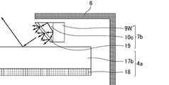
- the auxiliary illumination unit 7b includes a light guide plate 10c and a white LED 9W 'as an auxiliary light source.
- the light guide plate 10 c is disposed on the back side of the outer frame portion 6.
- the LED 9W ' is disposed on the back side of the outer frame portion 6 and adjacent to the end portion of the light guide plate 10c. Therefore, according to the mirror display of the second embodiment, the LED 9W 'becomes difficult to be visually recognized from the observation surface side, so that the design can be improved.
- FIG. 5 a state in which one LED 9 ⁇ / b> W ′ is disposed adjacent to the end of the light guide plate 10 c is shown. However, in reality, when viewed in plan from the observation surface side, the five LEDs are equally spaced. Has been placed.
- the light guide plate 10c is made of acrylic resin and has a thickness of 2 mm.
- the cross-sectional shape of the light guide plate 10c is a right-angled isosceles triangle.
- An AG film 19 for scattering light was bonded to the surface corresponding to the opposite side of the right angle.
- the thickness of the light guide plate 10c is not particularly limited, it is preferably 5 mm or less, preferably 3 mm or less from the viewpoint of improving the design by reducing the distance between the half mirror plate 4 a and the outer frame portion 6. More preferred. In commercially available televisions and monitors, the distance between the screen surface and the housing is often about 5 mm. Therefore, by setting the thickness of the light guide plate 10c to 5 mm or less, a mirror display can be manufactured without changing anything other than the casing, which is advantageous in terms of manufacturing cost.
- the auxiliary illumination unit 7b can emit light to the observation surface side in the mirror mode based on the principle shown in FIG.
- FIG. 6 is an explanatory diagram in which the auxiliary lighting unit in FIG. 5 is enlarged.
- the light emitted from the LED 9 ⁇ / b> W ′ in the mirror mode is repeatedly reflected on the surface in the light guide plate 10 c and then emitted to the outside through the AG film 19. Thereafter, the light emitted from the AG film 19 is reflected by the surface of the half mirror plate 4a and emitted to the observation surface side.
- the auxiliary illumination unit 7b is disposed closer to the observation surface than the liquid crystal display device 2a, it is not necessary to consider the light transmission loss in the liquid crystal display device 2a, and the white color of the liquid crystal display device 2a is not necessary. It is possible to illuminate the object with light having higher brightness than that at the time of display. Therefore, according to the mirror display of Example 2, the visibility in the dark place at the time of mirror mode can fully be improved.
- Example 3 relates to the first mirror display of the present invention, wherein the auxiliary illumination unit includes an auxiliary light source disposed on the back side of the outer frame portion, and a scatterer disposed on the observation surface side of the half mirror layer. This is the case. Since the mirror display of Example 3 is the same as the mirror display of Example 1 except these structures, description is abbreviate
- FIG. 7 is a schematic plan view showing a mirror display of Example 3.
- FIG. 7 in the mirror display 1c, the display area AR1 and the mirror area AR2 having the same size are arranged in the area surrounded by the housing 5.
- the auxiliary illumination unit 7c is arranged along two opposing sides of the display area AR1 (mirror area AR2).
- the auxiliary lighting unit 7c is arranged at two places, but may be arranged at one place or three or more places.
- the arrangement location of the auxiliary illumination unit 7c is not limited to the positions along the two opposite left and right sides of the display area AR1 (mirror area AR2), and may be any position along the four upper, lower, left and right sides. Good.
- FIG. 8 is a schematic cross-sectional view showing a cross section of a portion corresponding to the line segment C-C ′ in FIG.
- the mirror display 1c includes a liquid crystal display device 2a, an air layer 3, and a half mirror plate 4a in order from the back side to the observation surface side.
- the mirror display 1c further includes a housing 5 that holds the liquid crystal display device 2a and the half mirror plate 4a, and an auxiliary illumination unit 7c that is disposed at a position corresponding to FIG. 7 on the outer periphery of the half mirror plate 4a. Yes.
- the half mirror plate 4a includes a reflective polarizing plate 18 as a half mirror layer and a glass substrate 17b as a base material for holding the half mirror layer in order from the back side to the observation surface side.
- the reflective polarizing plate 18 and the glass substrate 17b were bonded together via an adhesive (not shown).
- As the glass substrate 17b non-alkali glass was used as a material, and the thickness was 3 mm.
- the auxiliary illumination unit 7c has a scatterer 20 and a white LED 9W 'as an auxiliary light source.
- the scatterer 20 was disposed on the surface of the glass substrate 17b on the reflective polarizing plate 18 side.
- the LED 9W ' is disposed on the back side of the outer frame 6 and adjacent to the end of the half mirror plate 4a. Therefore, according to the mirror display of Example 3, the LED 9W 'becomes difficult to be visually recognized from the observation surface side, so that the design can be improved.
- the end of the half mirror plate 4a shows a state in which one LED 9W ′ is arranged adjacent to each other, but in reality, when viewed in plan from the observation surface side, the five LEDs are equally spaced. Is arranged in.
- the thickness of the glass substrate 17b is preferably 1.5 mm or more from the viewpoint of efficiently making the light emitted from the LED 9W 'incident on the glass substrate 17b. Even when the thickness of the glass substrate 17b is less than 1.5 mm, the incidence efficiency to the glass substrate 17b can be increased by using a reflector.
- the scatterer 20 white pigment ink was used as a material and printed on the glass substrate 17b.
- the shape of the scatterer 20 was a round shape having a diameter of 1 mm when viewed from the observation surface side, and the distance between the scatterers was 2 mm.
- the shape of the scatterer 20 is not limited to a round shape, and may be a shape having a corner such as a square or a triangle.
- 8 shows a state in which the scatterers 20 are arranged in four rows so as to be parallel to the short side direction of the glass substrate 17b (the direction perpendicular to the paper surface in FIG. 8). Has been.
- the scatterer 20 is disposed in order to eliminate the condition of total reflection of light propagating through the half mirror plate 4a.
- the scatterer 20 may have a decorative pattern carved on the glass substrate 17b in addition to a dot-like structure such as a round shape.
- positioning location of the scatterer 20 is not limited to the surface by the side of the reflective polarizing plate 18 of the glass substrate 17b, The surface by the side of the glass substrate 17b of the reflective polarizing plate 18 may be sufficient.
- the auxiliary illumination unit 7c can emit light to the observation surface side in the mirror mode based on the principle shown in FIG.
- FIG. 9 is an explanatory diagram in which the auxiliary lighting unit in FIG. 8 is enlarged.
- the light emitted from the LED 9W 'in the mirror mode is repeatedly reflected on the surface within the glass substrate 17b, and then scattered by the scatterer 20 and emitted toward the observation surface.
- the auxiliary illumination unit 7c is disposed closer to the observation surface than the liquid crystal display device 2a, it is not necessary to consider light transmission loss in the liquid crystal display device 2a, and the white color of the liquid crystal display device 2a is not necessary. It is possible to illuminate the object with light having higher brightness than that at the time of display. Therefore, according to the mirror display of Example 3, the visibility in the dark place at the time of mirror mode can fully be improved.
- Example 4 relates to the first mirror display of the present invention described above, in which the auxiliary illumination unit includes an auxiliary light source disposed on the back side of the backlight unit of the liquid crystal display device. Since the mirror display of Example 4 is the same as the mirror display of Example 1 except these structures, description is abbreviate
- FIG. 10 is a schematic plan view showing a mirror display of Example 4.
- the display area AR1 and the mirror area AR2 having the same size are arranged in the area surrounded by the casing 5.
- the auxiliary illumination unit 7d is arranged in the display area AR1 (mirror area AR2).
- the auxiliary lighting units 7d are arranged at four places, but other numbers may be arranged. Further, the location of the auxiliary illumination unit 7d may be any position within the display area AR1 (mirror area AR2).
- FIG. 11 is a schematic cross-sectional view showing a cross section of a portion corresponding to the line segment D-D ′ in FIG. 10.
- the mirror display 1d includes a liquid crystal display device 2a, an air layer 3, and a half mirror plate 4a in order from the back surface side to the observation surface side.
- the mirror display 1d further includes a housing 5 that holds the liquid crystal display device 2a and the half mirror plate 4a, and an auxiliary light source disposed at a position corresponding to FIG. 10 on the back side of the backlight unit 8a that the liquid crystal display device 2a has.
- As an LED 9W ′ As an LED 9W ′. Therefore, according to the mirror display of Example 4, the LED 9W 'becomes difficult to be visually recognized from the observation surface side, so that the design can be improved.
- the auxiliary illumination unit 7d can emit light to the observation surface side in the mirror mode by setting the liquid crystal display panel 11a in a region overlapping with the LED 9W 'to the transmission state when the LED 9W' is turned on.
- the LED 9W ′ is controlled separately from the LED 9W as the display light source and has a higher luminance than the LED 9W. Therefore, the auxiliary illumination unit 7d uses the LED 9W as a liquid crystal display. It is possible to illuminate the object with light having a higher luminance than when the device 2a displays white. Therefore, according to the mirror display of Example 4, the visibility in the dark place at the time of mirror mode can fully be improved.
- the auxiliary light source may be configured by arranging a plurality of LEDs densely.
- Example 5 relates to the first mirror display of the present invention described above, in which the auxiliary illumination unit includes an auxiliary light source disposed on the back side of the half mirror plate. Further, the present invention relates to a configuration in which the size of the liquid crystal display device is smaller than the size of the half mirror plate when viewed in plan from the observation surface side. Since the mirror display of Example 5 is the same as the mirror display of Example 1 except these structures, description is abbreviate
- FIG. 12 is a schematic plan view illustrating a mirror display of Example 5.
- a display area AR1 and a mirror area AR2 larger than the display area AR1 are arranged in an area surrounded by the housing 5.
- the auxiliary illumination unit 7e is disposed in the mirror area AR2 and in the area outside the display area AR1.
- the auxiliary lighting unit 7e is arranged at one place, but may be arranged at two or more places. Further, the location of the auxiliary illumination unit 7e may be any position within the mirror area AR2 and within the area outside the display area AR1.
- FIG. 13 is a schematic cross-sectional view showing a cross section of a portion corresponding to line E-E ′ in FIG.
- the mirror display 1e includes a liquid crystal display device 2a and a half mirror plate 4a in order from the back side to the observation surface side.
- the mirror display 1e further includes a housing 5 that holds the liquid crystal display device 2a and the half mirror plate 4a, an area outside the region where the liquid crystal display device 2a and the half mirror plate 4a face each other, and a back side of the half mirror plate 4a.
- an LED 9W ′ as an auxiliary light source arranged at a position corresponding to FIG. 12 on the back side of the opening 22 provided in the light shielding body 21.
- the LED 9W ′ is disposed on the back side of the opening 22, but may be disposed at the same position as the opening 22.
- the size of the liquid crystal display device 2a was made smaller than the size of the half mirror plate 4a when viewed in plan from the observation surface side. Thereby, the display mode and the mirror mode can be used together, and the area outside the display area can be used as a mirror. Further, the size of the half mirror plate 4a is set to be approximately the same as the outer shape of the mirror display 1e.
- the light-shielding body 21 what stuck the black polyethylene terephthalate (PET) film through the adhesive (not shown) was used.
- black paper plastic resin such as acrylic, ABS, or vinyl chloride may be used.
- the light-shielding body 21 maintains the function of the half-mirror plate 4a by shielding a region not facing the liquid crystal display device 2a on the back side of the half-mirror plate 4a. Further, as long as the light shield 21 is disposed on the back side of the half mirror plate 4a, the light shield 21 may be bonded to the half mirror plate 4a via an adhesive, or may be separately disposed without being bonded to the half mirror plate 4a. Also good. Alternatively, the light shielding body 21 may be formed by directly applying acrylic paint or the like to a predetermined position on the back side of the half mirror plate 4a.
- the auxiliary illumination unit 7e can transmit light emitted from the LED 9W ′ through the opening 22 and the half mirror plate 4a in a region overlapping the LED 9W ′ to emit light to the observation surface side in the mirror mode. it can.
- the auxiliary illumination unit 7e since the auxiliary illumination unit 7e does not pass through the liquid crystal display device 2a, it can illuminate the object with light having a higher luminance than when the liquid crystal display device 2a displays white. Therefore, according to the mirror display of Example 5, the visibility in the dark place at the time of mirror mode can fully be improved.
- Example 6 relates to the first mirror display of the present invention, wherein the auxiliary illumination unit includes an auxiliary light source disposed on the back side of the outer frame portion, and a scatterer disposed on the observation surface side of the half mirror layer. This is the case. Further, the present invention relates to a configuration in which the size of the liquid crystal display device is smaller than the size of the half mirror plate when viewed in plan from the observation surface side. Since the mirror display of Example 6 is the same as the mirror display of Example 3 except for the location of the scatterers and the size of the liquid crystal display device and the half mirror plate, the description of overlapping points is omitted.
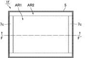
- FIG. 14 is a schematic plan view showing a mirror display of Example 6.
- a display area AR1 and a mirror area AR2 larger than the display area AR1 are arranged in an area surrounded by the housing 5.
- the auxiliary lighting unit 7c is disposed outside the display area AR1 and in the area on the back side of the housing 5.
- the auxiliary lighting units 7c are arranged at two places, but may be arranged at one place or three or more places.
- assistant illumination unit 7c may be any position in the area
- FIG. 15 is a schematic cross-sectional view showing a cross section of a portion corresponding to the line segment F-F ′ in FIG. 14.
- the mirror display 1f includes a liquid crystal display device 2a and a half mirror plate 4a in order from the back side to the observation surface side.
- the mirror display 1f further includes a housing 5 that holds the liquid crystal display device 2a and the half mirror plate 4a, a region outside the region where the liquid crystal display device 2a and the half mirror plate 4a face each other, and the back side of the half mirror plate 4a.
- the auxiliary illumination unit 7c arranged at a position corresponding to FIG. 14 on the outer peripheral portion of the half mirror plate 4a.
- the light shield 21 the same one as in Example 5 was used.
- the size of the liquid crystal display device 2a was made smaller than the size of the half mirror plate 4a when viewed in plan from the observation surface side. Thereby, the display mode and the mirror mode can be used together, and the area outside the display area can be used as a mirror. Further, the size of the half mirror plate 4a is set to be approximately the same as the outer shape of the mirror display 1f.
- the auxiliary illumination unit 7c has a scatterer 20 and a white LED 9W 'as an auxiliary light source.
- the scatterer 20 was disposed outside the region where the liquid crystal display device 2a and the half mirror plate 4a face each other and on the reflective polarizing plate 18 side of the glass substrate 17b.
- the LED 9W ' is disposed on the back side of the outer frame 6 and adjacent to the end of the half mirror plate 4a. Therefore, according to the mirror display of Example 6, the LED 9W 'becomes difficult to be visually recognized from the observation surface side, so that the design can be improved.
- the auxiliary illumination unit 7c can emit light to the observation surface side in the mirror mode based on the same principle as in the third embodiment. Therefore, according to the mirror display of Example 6, the visibility in the dark place at the time of mirror mode can fully be improved.
- Example 7 relates to the first mirror display of the present invention, in which the auxiliary illumination unit includes an auxiliary light source disposed on the back side of the backlight unit of the liquid crystal display device. Further, the present invention relates to a configuration in which the size of the liquid crystal display device is smaller than the size of the half mirror plate when viewed in plan from the observation surface side. Since the mirror display of Example 7 is the same as the mirror display of Example 4 except for the size of the liquid crystal display device and the half mirror plate, the description of overlapping points is omitted.
- FIG. 16 is a schematic plan view illustrating a mirror display according to the seventh embodiment.
- a display area AR1 and a mirror area AR2 larger than the display area AR1 are arranged in an area surrounded by the casing 5.
- An auxiliary lighting unit 7d is arranged in the display area AR1.
- the auxiliary lighting units 7d are arranged at four places, but other numbers may be arranged. Further, the location of the auxiliary lighting unit 7d may be any position in the display area AR1.
- FIG. 17 is a schematic cross-sectional view showing a cross section of a portion corresponding to a line segment G-G ′ in FIG. 16.
- the mirror display 1g includes a liquid crystal display device 2a and a half mirror plate 4a in order from the back side to the observation surface side.
- the mirror display 1g further includes a housing 5 that holds the liquid crystal display device 2a and the half mirror plate 4a, a region outside the region where the liquid crystal display device 2a and the half mirror plate 4a face each other, and the back side of the half mirror plate 4a.
- the LED 9W ′ as an auxiliary light source disposed at a position corresponding to FIG. 16 on the back side of the backlight unit 8a of the liquid crystal display device 2a.
- the same one as in Example 5 was used.
- the size of the liquid crystal display device 2a was made smaller than the size of the half mirror plate 4a when viewed in plan from the observation surface side. Thereby, the display mode and the mirror mode can be used together, and the area outside the display area can be used as a mirror.
- the size of the half mirror plate 4a was set to be approximately the same as the outer shape of the mirror display 1g.
- the auxiliary illumination unit 7d can emit light to the observation surface side in the mirror mode by setting the liquid crystal display panel 11a in a region overlapping with the LED 9W 'to the transmission state when the LED 9W' is turned on.
- the LED 9W ′ is controlled separately from the LED 9W as the display light source and has a higher luminance than the LED 9W. Therefore, the auxiliary illumination unit 7d uses the LED 9W as a liquid crystal display. It is possible to illuminate the object with light having a higher luminance than when the device 2a displays white. Therefore, according to the mirror display of Example 7, the visibility in the dark place at the time of mirror mode can fully be improved.
- Example 8 relates to the second mirror display of the present invention described above, in which the auxiliary illumination unit emits light emitted from a part of the display light source of the liquid crystal display device, a part where the thickness of the color filter layer is thinner than the other part In this case, the light is emitted to the observation surface side.
- the mirror display according to the eighth embodiment is substantially the same as the mirror display according to the first embodiment except for these configurations, and thus the description of overlapping points is omitted.
- FIG. 18 is a schematic plan view illustrating a mirror display according to the eighth embodiment.
- a display area AR1 and a mirror area AR2 having the same size are arranged in the mirror display 1h.
- the auxiliary lighting unit 7f is arranged on the outer periphery of the display area AR1 (mirror area AR2).
- the auxiliary illumination unit 7f is arranged on the outer periphery of the display area AR1 (mirror area AR2), but the position along the two opposite sides or one side of the display area AR1 (mirror area AR2), or the display You may arrange
- the location of the auxiliary lighting unit 7f may be determined as appropriate in accordance with the size and usage of the mirror display 1h. The same applies to Examples 9 to 18.
- FIG. 19 is a schematic cross-sectional view showing a cross section of a portion corresponding to the line H-H ′ in FIG.
- the mirror display 1h includes a liquid crystal display device 2b, an air layer 3, and a half mirror plate 4a in order from the back side to the observation surface side.
- the liquid crystal display device 2b includes an auxiliary illumination unit 7f arranged at a position corresponding to FIG. 18 on the outer periphery of the display area AR1 (mirror area AR2).
- the size of the liquid crystal display device 2b was the same as that of the half mirror plate 4a when viewed in plan from the observation surface side.
- the liquid crystal display device 2b and the half mirror plate 4a were fixed by fitting the upper and lower ends of the half mirror plate 4a into a pair of aluminum rails attached to the upper and lower ends of the liquid crystal display device 2b in a frame shape.
- the air layer 3 is a space formed in a slight gap between the liquid crystal display device 2b and the half mirror plate 4a.
- the liquid crystal display device 2b includes a backlight unit 8b and a liquid crystal display panel 11b in order from the back side to the observation surface side.
- the backlight unit 8b has a white LED 9W as a display light source and a diffusion plate 23 arranged so as to cover the LED 9W, and a direct type is adopted.
- a diffusion plate (trade name: Sumipex (registered trademark) E) manufactured by Sumitomo Chemical Co., Ltd. was used.
- the liquid crystal display panel 11b includes an absorption polarizing plate 12a (second polarizing plate), a thin film transistor array substrate 13 (second substrate), a liquid crystal layer 14, and a color filter substrate 15b (in order from the back side to the observation surface side).
- the display mode and driving method of the liquid crystal display panel 11b are the same as those in the first embodiment.
- the color filter substrate 15b includes a glass substrate 17a and color filter layers 16R, 16G, 16B, 16R ′ (red), 16G ′ (green), and 16B ′ (blue) disposed on the thin film transistor array substrate 13 side of the glass substrate 17a. And have.
- the thicknesses of the color filter layers 16R ', 16G', and 16B ' are half the thicknesses of the color filter layers 16R, 16G, and 16B, respectively.
- Color filter layers 16R ', 16G', and 16B ' are disposed on the outer periphery of the color filter substrate 15b, and color filter layers 16R, 16G, and 16B are disposed on the other portions.
- the auxiliary illumination unit 7f includes a part of the display light source (LED 9W). Therefore, according to the mirror display of Example 8, since LED9W used as a part of auxiliary lighting unit 7f is hard to be visually recognized from the observation surface side, design property can be improved.
- the auxiliary illumination unit 7f is a portion (first portion) in which the color filter layers 16R ′, 16G ′, and 16B ′ are arranged to emit light emitted from the LED 9W used as a part of the auxiliary illumination unit 7f in the mirror mode. Through the observation surface. Of the light emitted from the LED 9W used as a part of the auxiliary lighting unit 7f, the amount of light absorbed by the portion where the color filter layers 16R ′, 16G ′, 16B ′ are arranged is the color filter layers 16R, 16G, 16B.
- the auxiliary illumination unit 7f has a portion (third portion) in which the concentration of the material (for example, the color pigment) constituting the color filter layer is lower than other portions. ) Through which light is emitted toward the observation surface side. Also by this modification, the same effects as those of the eighth embodiment can be obtained.
- the portion corresponding to the auxiliary lighting unit 7f of the liquid crystal display panel 11b is made a black display screen in a state where no voltage is applied, or the LED 9W used as a part of the auxiliary lighting unit 7f is turned off, thereby
- the display can be prevented from being hindered. Further, even when the light amount is adjusted using a local dimming backlight as a light source used as a part of the auxiliary illumination unit 7f, it is possible not to disturb the image display.
- the LED 9W used as a part of the auxiliary lighting unit 7f may be controlled by a circuit different from other display light sources, or may be controlled by the same circuit. From the viewpoint of improving the usability, it is preferable to be controlled by another circuit.
- Example 9 relates to the second mirror display of the present invention, in which the auxiliary illumination unit transmits light emitted from a part of the display light source of the liquid crystal display device through the portion where the color filter layer is not present. This is a case of emitting light to the side. Since the mirror display of Example 9 is the same as the mirror display of Example 8 except these structures, description is abbreviate
- FIG. 20 is a schematic cross-sectional view showing a mirror display of Example 9.
- the mirror display 1i includes a liquid crystal display device 2c, an air layer 3, and a half mirror plate 4a in order from the back side to the observation surface side.
- the liquid crystal display device 2c includes an auxiliary illumination unit 7g disposed on the outer periphery of the display area AR1 (mirror area AR2).
- the liquid crystal display device 2c includes a backlight unit 8b and a liquid crystal display panel 11c in order from the back side to the observation surface side.
- the liquid crystal display panel 11c has an absorption polarizing plate 12a, a thin film transistor array substrate 13, a liquid crystal layer 14, a color filter substrate 15c, and an absorption polarizing plate 12b in order from the back side to the observation surface side.
- the display mode and driving method of the liquid crystal display panel 11c were the same as those in Example 8.
- the color filter substrate 15c has a glass substrate 17a and color filter layers 16R, 16G, and 16B disposed on the glass substrate 17a on the thin film transistor array substrate 13 side. No color filter layer was disposed on the outer periphery of the color filter substrate 15c.
- the auxiliary lighting unit 7g includes a part of the display light source (LED 9W). Therefore, according to the mirror display of Example 9, the LED 9W used as a part of the auxiliary illumination unit 7g is difficult to be visually recognized from the observation surface side, so that the design can be improved.
- the auxiliary illumination unit 7g emits light emitted from the LED 9W used as a part of the auxiliary illumination unit 7g to the observation surface side through a portion where the color filter layer is not present (second portion).
- Each of the color filter layers 16R, 16G, and 16B transmits only about 1/3 of the visible light having a wavelength of 400 to 700 nm, and the other about 2/3 of the light of each color. Absorbed by the filter layer. The area of the pixel corresponding to each color filter layer is divided into 1/3 of the whole.
- Example 10 relates to the second mirror display of the present invention, in which the auxiliary illumination unit emits light emitted from a part of the display light source of the liquid crystal display device, the pixel having no color filter layer, and the color filter layer This is a case where the light is emitted to the observation surface side through a portion constituted by a part of existing pixels. Since the mirror display of Example 10 is the same as the mirror display of Example 8 except these structures, description is abbreviate
- FIG. 21 is a schematic cross-sectional view showing the mirror display of Example 10.
- the mirror display 1j includes a liquid crystal display device 2d, an air layer 3, and a half mirror plate 4a in order from the back surface side to the observation surface side.
- the liquid crystal display device 2d includes an auxiliary illumination unit 7h disposed on the outer periphery of the display area AR1 (mirror area AR2).
- the liquid crystal display device 2d includes a backlight unit 8b and a liquid crystal display panel 11d in order from the back side to the observation surface side.
- the liquid crystal display panel 11d includes an absorption polarizing plate 12a, a thin film transistor array substrate 13, a liquid crystal layer 14, a color filter substrate 15d, and an absorption polarizing plate 12b in this order from the back side to the observation surface side.
- the display mode and driving method of the liquid crystal display panel 11d were the same as those in Example 8.
- the color filter substrate 15d includes a glass substrate 17a and color filter layers 16R, 16G, 16B, and 16W arranged on the thin film transistor array substrate 13 side of the glass substrate 17a.
- the pixel on which the color filter layer 16W is arranged is a pixel for white display in which no color filter layer is present.
- the color filter layers 16R, 16G, 16B, and 16W are disposed on the outer peripheral portion of the color filter substrate 15d, and the color filter layers 16R, 16G, and 16B are disposed on the other portions.
- the auxiliary illumination unit 7h includes a part of the display light source (LED 9W). Therefore, according to the mirror display of Example 10, the LED 9W used as a part of the auxiliary illumination unit 7h is difficult to be visually recognized from the observation surface side, so that the design can be improved.
- the color filter layers 16R, 16G, 16B, and 16W are arranged.
- the luminance of the light after passing through the auxiliary illumination unit 7h is higher than the luminance at the time of white display of the liquid crystal display device 2d when measured on the observation surface side. Therefore, according to the mirror display of Example 10, the visibility in the dark place at the time of mirror mode can fully be improved.
- Example 11 relates to the second mirror display of the present invention, and the auxiliary illumination unit emits light emitted from a part of the display light source of the liquid crystal display device without a polarizing plate on the observation surface side of the liquid crystal display panel. In this case, the light is emitted to the observation surface side through the portion. Since the mirror display of Example 11 is the same as the mirror display of Example 8 except these structures, description is abbreviate
- FIG. 22 is a schematic cross-sectional view showing the mirror display of Example 11.
- the mirror display 1k includes a liquid crystal display device 2e, an air layer 3, and a half mirror plate 4a in order from the back surface side to the observation surface side.
- the liquid crystal display device 2e includes an auxiliary illumination unit 7i disposed on the outer periphery of the display area AR1 (mirror area AR2).
- the liquid crystal display device 2e includes a backlight unit 8b and a liquid crystal display panel 11e in order from the back side to the observation surface side.
- the liquid crystal display panel 11e has an absorption polarizing plate 12a, a thin film transistor array substrate 13, a liquid crystal layer 14, a color filter substrate 15a, and an absorption polarizing plate 12b in order from the back side to the observation surface side.
- the absorptive polarizing plate 12b was not disposed on the outer periphery of the liquid crystal display panel 11e.
- the display mode and driving method of the liquid crystal display panel 11e were the same as those in Example 8.
- the auxiliary lighting unit 7i includes a part of the display light source (LED 9W). Therefore, according to the mirror display of Example 11, the LED 9W used as a part of the auxiliary illumination unit 7i is difficult to be visually recognized from the observation surface side, so that the design can be improved.
- the auxiliary illumination unit 7i in the mirror mode, transmits light emitted from the LED 9W used as a part of the auxiliary illumination unit 7i via the portion where the absorption-type polarizing plate 12b is not present (fifth portion).
- the absorption polarizing plates 12a and 12b are set to have a single transmittance of 42% and a parallel transmittance of 37%, the amount of light after passing through the portion where the absorption polarizing plate 12b does not exist is the absorption light polarizing plate 12b. This is 1.14 times (42% / 37% ⁇ 1.14) the amount of light after passing through the arranged portion.
- the luminance of the light after passing through the auxiliary illumination unit 7i is higher than the luminance at the time of white display of the liquid crystal display device 2e when measured on the observation surface side. Therefore, according to the mirror display of Example 11, the visibility in the dark place at the time of mirror mode can fully be improved.
- Example 12 relates to the second mirror display of the present invention, wherein the auxiliary illumination unit emits light emitted from a part of the display light source of the liquid crystal display device, and the portion where the polarizing plate on the back side of the liquid crystal display panel does not exist In this case, the light is emitted to the observation surface side. Since the mirror display of Example 12 is the same as the mirror display of Example 8 except these structures, description is abbreviate
- FIG. 23 is a schematic cross-sectional view showing a mirror display of Example 12.
- the mirror display 1m includes a liquid crystal display device 2f, an air layer 3, and a half mirror plate 4a in order from the back side to the observation surface side.
- the liquid crystal display device 2f includes an auxiliary illumination unit 7j disposed on the outer periphery of the display area AR1 (mirror area AR2).
- the liquid crystal display device 2f includes a backlight unit 8b and a liquid crystal display panel 11f in order from the back side to the observation surface side.
- the liquid crystal display panel 11f includes an absorption polarizing plate 12a, a thin film transistor array substrate 13, a liquid crystal layer 14, a color filter substrate 15a, and an absorption polarizing plate 12b in order from the back side to the observation surface side.
- the absorptive polarizing plate 12a was not disposed on the outer periphery of the liquid crystal display panel 11f.
- the display mode and driving method of the liquid crystal display panel 11f were the same as those in Example 8.
- the auxiliary lighting unit 7j includes a part of the display light source (LED 9W). Therefore, according to the mirror display of Example 12, the LED 9W used as a part of the auxiliary illumination unit 7j is difficult to be visually recognized from the observation surface side, so that the design can be improved.
- the auxiliary illumination unit 7j emits light emitted from the LED 9W used as a part of the auxiliary illumination unit 7j through the portion where the absorption-type polarizing plate 12a is not present (fifth portion).
- the absorption polarizing plates 12a and 12b are set to have a single transmittance of 42% and a parallel transmittance of 37%, the amount of light after passing through a portion where the absorption polarizing plate 12a does not exist is determined by the absorption polarizing plate 12a. This is 1.14 times (42% / 37% ⁇ 1.14) the amount of light after passing through the arranged portion.
- the luminance of the light after passing through the auxiliary lighting unit 7j is higher than the luminance at the time of white display of the liquid crystal display device 2f when measured on the observation surface side. Therefore, according to the mirror display of Example 12, the visibility in the dark place at the time of mirror mode can fully be improved.
- the auxiliary lighting unit 7j can perform toning.
- Example 13 relates to the second mirror display of the present invention described above, and the auxiliary illumination unit converts the light emitted from a part of the display light source of the liquid crystal display device into polarizing plates on the observation surface side and the back surface side of the liquid crystal display panel. In this case, the light is emitted to the observation surface side through a portion where no exists. Since the mirror display of Example 13 is the same as the mirror display of Example 8 except these structures, description is abbreviate
- FIG. 24 is a schematic cross-sectional view showing the mirror display of Example 13.
- the mirror display 1n includes a liquid crystal display device 2g, an air layer 3, and a half mirror plate 4a in order from the back surface side to the observation surface side.
- the liquid crystal display device 2g includes an auxiliary illumination unit 7k disposed on the outer periphery of the display area AR1 (mirror area AR2).
- the liquid crystal display device 2g includes a backlight unit 8b and a liquid crystal display panel 11g in order from the back surface side to the observation surface side.
- the liquid crystal display panel 11g has an absorption polarizing plate 12a, a thin film transistor array substrate 13, a liquid crystal layer 14, a color filter substrate 15a, and an absorption polarizing plate 12b in order from the back side to the observation surface side.
- Absorption type polarizing plates 12a and 12b were not disposed on the outer peripheral portion of the liquid crystal display panel 11g.
- the display mode and driving method of the liquid crystal display panel 11g were the same as those in Example 8.
- the auxiliary lighting unit 7k includes a part of the display light source (LED 9W). Therefore, according to the mirror display of Example 13, the LED 9W used as a part of the auxiliary illumination unit 7k is difficult to be visually recognized from the observation surface side, so that the design can be improved.
- the auxiliary illumination unit 7k observes the light emitted from the LED 9W used as a part of the auxiliary illumination unit 7k in the mirror mode through the portion where the absorption-type polarizing plates 12a and 12b are not present (fifth portion). The light is emitted to the surface side. Since the absorption polarizing plates 12a and 12b are set to have a parallel transmittance of 37%, the amount of light after passing through the portion where the absorption polarizing plates 12a and 12b do not exist is arranged as the absorption polarizing plates 12a and 12b. 2.7 times the amount of light after passing through the portion (100% / 37% ⁇ 2.7).
- the luminance of the light after passing through the auxiliary illumination unit 7k is higher than the luminance at the time of white display of the liquid crystal display device 2g when measured on the observation surface side. Therefore, according to the mirror display of Example 13, the visibility in the dark place in the mirror mode can be sufficiently improved. Note that if the LEDs of three colors R, G, and B are used instead of the LED 9W, the auxiliary lighting unit 7k can perform toning.
- Example 14 relates to the second mirror display of the present invention, in which the auxiliary illumination unit emits light emitted from a part of the display light source of the liquid crystal display device, the part where the color filter layer is not present, and the liquid crystal display panel. This is a case where the light is emitted to the observation surface side through a portion where the polarizing plate on the observation surface side and the back surface side does not exist. Since the mirror display of Example 14 is the same as the mirror display of Example 8 except these structures, description is abbreviate
- FIG. 25 is a schematic cross-sectional view showing the mirror display of Example 14.
- the mirror display 1p includes a liquid crystal display device 2h, an air layer 3, and a half mirror plate 4a in order from the back surface side to the observation surface side.
- the liquid crystal display device 2h includes an auxiliary illumination unit 7m disposed on the outer periphery of the display area AR1 (mirror area AR2).
- the liquid crystal display device 2h includes a backlight unit 8b and a liquid crystal display panel 11h in order from the back side to the observation surface side.
- the liquid crystal display panel 11h includes an absorption polarizing plate 12a, a thin film transistor array substrate 13, a liquid crystal layer 14, a color filter substrate 15c, and an absorption polarizing plate 12b in this order from the back side to the observation surface side.
- the color filter layer and the absorption polarizing plates 12a and 12b were not arranged on the outer peripheral portion of the liquid crystal display panel 11h.
- the display mode and driving method of the liquid crystal display panel 11h were the same as those in Example 8.
- the auxiliary illumination unit 7m includes a part of the display light source (LED 9W). Therefore, according to the mirror display of Example 14, the LED 9W used as a part of the auxiliary illumination unit 7m is difficult to be visually recognized from the observation surface side, so that the design can be improved.
- the auxiliary illumination unit 7m is configured to divide the light emitted from the LED 9W used as a part of the auxiliary illumination unit 7m into a portion where the color filter layer is not present (second portion), and the absorption polarizing plate 12a, The light is emitted toward the observation surface through a portion (fifth portion) where 12b does not exist.
- the amount of light after passing through the portion where the color filter layer does not exist is three times the amount of light after passing through the portion where the color filter layers 16R, 16G, and 16B are disposed.
- the amount of light after passing through the portion where the absorption-type polarizing plates 12a and 12b do not exist is the amount of light after passing through the portion where the absorption-type polarizing plates 12a and 12b are arranged. 2.7 times. Therefore, the amount of light after passing through the part where the color filter layer does not exist and the part where the absorption type polarizing plates 12a and 12b do not exist is the part where the color filter layers 16R, 16G and 16B are arranged, and the absorption type polarization. The amount of light after passing through the portion where the plates 12a and 12b are disposed is 8.1 times.
- the luminance of the light after passing through the auxiliary illumination unit 7m is higher than the luminance at the time of white display of the liquid crystal display device 2h when measured on the observation surface side. Therefore, according to the mirror display of Example 14, the visibility in the dark place at the time of mirror mode can fully be improved.
- the auxiliary illumination unit 7m can perform toning.
- Example 15 relates to the second mirror display of the present invention described above, in which the auxiliary illumination unit emits light from the portion where the display light source of the liquid crystal display device is arranged more than the other portions to the observation surface side. is there. Since the mirror display of Example 15 is the same as the mirror display of Example 8 except these structures, description is abbreviate
- FIG. 26 is a schematic cross-sectional view showing the mirror display of Example 15.
- the mirror display 1q includes a liquid crystal display device 2i, an air layer 3, and a half mirror plate 4a in order from the back surface side to the observation surface side.
- the liquid crystal display device 2i includes an auxiliary illumination unit 7n disposed on the outer periphery of the display area AR1 (mirror area AR2).
- the liquid crystal display device 2i includes a backlight unit 8c and a liquid crystal display panel 11a in order from the back surface side to the observation surface side.
- the backlight unit 8c has a white LED 9W as a display light source and a diffusion plate 23 arranged to cover the LED 9W, and a direct type is adopted. On the outer periphery of the backlight unit 8c, twice as many LEDs 9W as other parts are arranged.
- the auxiliary lighting unit 7n includes a portion where more display light sources (LEDs 9W) are arranged than other portions. Therefore, according to the mirror display of Example 15, the LED 9W used as a part of the auxiliary illumination unit 7n is difficult to be visually recognized from the observation surface side, so that the design can be improved.
- LEDs 9W display light sources
- the auxiliary illumination unit 7n emits light emitted from the portion (sixth portion) where the display light source (LED 9W) is disposed more than the other portions via the liquid crystal display panel 11a and the half mirror plate 4a.
- the light is emitted to the observation surface side. Since the number of LEDs 9W used as a part of the auxiliary lighting unit 7n is twice the number of LEDs arranged in other parts, the amount of emitted light is also doubled. Therefore, the luminance of the light after passing through the auxiliary illumination unit 7n is higher than the luminance at the time of white display of the liquid crystal display device 2i when measured on the observation surface side. Therefore, according to the mirror display of Example 15, the visibility in the dark place at the time of mirror mode can fully be improved.
- Example 16 relates to the second mirror display of the present invention, wherein the auxiliary illumination unit emits light emitted from the part where the display light source other than white is arranged, the part where the color filter layer is not present, and the liquid crystal display panel. It is a case where it radiate
- FIG. 27 is a schematic cross-sectional view showing a mirror display of Example 16.
- the mirror display 1r includes a liquid crystal display device 2j, an air layer 3, and a half mirror plate 4a in order from the back surface side to the observation surface side.
- the liquid crystal display device 2j includes an auxiliary illumination unit 7p disposed on the outer periphery of the display area AR1 (mirror area AR2).
- the liquid crystal display device 2j includes a backlight unit 8d and a liquid crystal display panel 11h in order from the back side to the observation surface side.
- the backlight unit 8d has a white LED 9W, a red LED 9R, a green LED 9G, a blue LED 9B as a display light source, and a diffusion plate 23 arranged so as to cover each LED. Is adopted. LEDs 9R, 9G, and 9B are disposed on the outer peripheral portion of the backlight unit 8d, and LEDs 9W are disposed on the other portions.
- the auxiliary lighting unit 7p includes a portion where the LEDs 9R, 9G, and 9B are disposed. Therefore, according to the mirror display of Example 16, the LED 9R, 9G, 9B used as a part of the auxiliary illumination unit 7p is difficult to be visually recognized from the observation surface side, so that the design can be improved.
- the auxiliary illumination unit 7p absorbs light emitted from the portion (seventh portion) where the LEDs 9R, 9G, and 9B are disposed in the mirror mode, the portion where the color filter layer is not present (second portion), and the absorption type The light is emitted to the observation surface side through a portion (fifth portion) where the polarizing plates 12a and 12b do not exist.
- the color filter layers 16R, 16G, and 16B are arranged for the amount of light after passing through the portion where the color filter layer does not exist and the portion where the absorption polarizing plates 12a and 12b do not exist. And the amount of light after passing through the portion where the absorption type polarizing plates 12a and 12b are disposed is 8.1 times.
- the luminance of the light after passing through the auxiliary illumination unit 7p is higher than the luminance at the time of white display of the liquid crystal display device 2j when measured on the observation surface side. Therefore, according to the mirror display of Example 16, the visibility in the dark place in the mirror mode can be sufficiently improved. In this case, since the three-color LEDs 9R, 9G, and 9B are used, the auxiliary lighting unit 7p can perform toning.
- Example 17 relates to the second mirror display of the present invention described above, wherein the size of the liquid crystal display panel is smaller than the size of the backlight unit when viewed in plan from the observation surface side.
- the auxiliary illumination unit emits light emitted from the portion where the display light source other than white is disposed to the observation surface side through a region outside the region where the liquid crystal display panel and the backlight unit face each other. This is the case.
- the mirror display of the seventeenth embodiment is the same as the mirror display of the sixteenth embodiment except for the size of the liquid crystal display panel.
- FIG. 28 is a schematic sectional view showing a mirror display of Example 17.
- the mirror display 1s includes a liquid crystal display device 2k, an air layer 3, and a half mirror plate 4a in order from the back surface side to the observation surface side.
- the liquid crystal display device 2k includes an auxiliary illumination unit 7q disposed on the outer periphery of the display area AR1 (mirror area AR2).
- the liquid crystal display device 2k includes a backlight unit 8d and a liquid crystal display panel 11a in order from the back side to the observation surface side.
- the size of the liquid crystal display panel 11a was made smaller than the size of the backlight unit 8d when viewed in plan from the observation surface side.
- the auxiliary lighting unit 7q is provided in a region outside the region where the liquid crystal display panel 11a and the backlight unit 8d face each other, and includes a portion where the LEDs 9R, 9G, and 9B are disposed. Therefore, according to the mirror display of Example 17, the LED 9R, 9G, 9B used as a part of the auxiliary illumination unit 7q is difficult to be visually recognized from the observation surface side, so that the design can be improved.
- the auxiliary illumination unit 7q emits light emitted from the portion (seventh portion) where the LEDs 9R, 9G, and 9B are disposed outside the region where the liquid crystal display panel 11a and the backlight unit 8d face each other. It is made to radiate
- the amount of light after having passed through the portion where the color filter layers 16R, 16G, and 16B are disposed and the portion where the absorption type polarizing plates 12a and 12b are disposed is transmitted. This is 8.1 times the amount of light. Therefore, the luminance of the light after passing through the auxiliary illumination unit 7q is higher than the luminance at the time of white display of the liquid crystal display device 2k when measured on the observation surface side. Therefore, according to the mirror display of Example 17, the visibility in the dark place at the time of mirror mode can fully be improved. In this case, since the three-color LEDs 9R, 9G, and 9B are used, the auxiliary lighting unit 7q can perform toning.
- the mirror display of the seventeenth embodiment can be realized by preparing the liquid crystal display panel 11a smaller than the size of the backlight unit 8d, as in the eighth to sixteenth embodiments, the manufacturing process of the liquid crystal display panel No change is required, which is advantageous in terms of manufacturing cost.
- Example 18 relates to the second mirror display of the present invention, in which a dielectric multilayer film is used as the half mirror layer. Further, when the size of the liquid crystal display panel is viewed in plan from the observation surface side, the size of the backlight unit is smaller, and the auxiliary illumination unit emits light emitted from the portion where the display light source other than white is disposed, This is a case where the liquid crystal display panel and the backlight unit emit light toward the observation surface through a region outside the region where the liquid crystal display panel and the backlight unit face each other. Since the mirror display of Example 18 is the same as the mirror display of Example 17 except for the half mirror layer, the description of overlapping points is omitted.
- FIG. 29 is a schematic sectional view showing a mirror display of Example 18.
- the mirror display 1t includes a liquid crystal display device 2k, an air layer 3, and a half mirror plate 4b in order from the back side to the observation surface side.
- the liquid crystal display device 2k includes an auxiliary illumination unit 7r disposed on the outer periphery of the display area AR1 (mirror area AR2).
- the half mirror plate 4b has a dielectric multilayer film 24 as a half mirror layer and a glass substrate 17b as a base material for holding the half mirror layer in order from the back surface side to the observation surface side.
- the dielectric multilayer film 24 and the glass substrate 17b were bonded together via an adhesive (not shown).
- dielectric multilayer film 24 As the dielectric multilayer film 24, a dielectric multilayer film (trade name: PICASUS (registered trademark)) manufactured by Toray Industries, Inc. was used. As the dielectric multilayer film 24, a mirror in which the reflectance is adjusted to an arbitrary value using the principle of optical interference, and a plurality of laminated dielectric thin films having different refractive indexes can be used. A multilayer film in which low refractive index titanium oxide (TiO 2 ) and high refractive index silicon dioxide (SiO 2 ) are alternately laminated, a multilayer film in which two types of PET having different refractive indexes are alternately laminated, and the like Can be mentioned.
- PICASUS registered trademark
- the auxiliary lighting unit 7r is provided in a region outside the region where the liquid crystal display panel 11a and the backlight unit 8d face each other, and includes a portion (seventh portion) in which the LEDs 9R, 9G, and 9B are disposed.
- the configuration is the same as that of the auxiliary lighting unit 7q of the seventeenth embodiment. Therefore, according to the mirror display of Example 18, the same effect as the mirror display of Example 17 can be obtained.
- the auxiliary lighting unit By providing a position sensor that measures the distance to the object on the observation surface side (for example, an observer), the auxiliary lighting unit automatically adjusts and adjusts the color in conjunction with the position sensor. Can do. Further, when an observer or the like approaches the mirror display, the mirror mode / display mode can be switched and the auxiliary lighting unit can be switched ON / OFF accordingly.
- the auxiliary lighting unit By providing an illuminance sensor that measures the brightness of the usage environment, the auxiliary lighting unit can automatically dim in conjunction with the illuminance sensor.
- C By providing a chromaticity sensor that measures the color tone of the usage environment, the auxiliary lighting unit can automatically adjust the color in conjunction with the chromaticity sensor.
- the auxiliary lighting unit can be switched ON / OFF using the remote controller of the display device.
- the auxiliary lighting unit can be used as a flash when taking a picture.
- the auxiliary lighting unit is provided with a function of adjusting and adjusting the light according to the usage environment, it is possible to produce a mirror mode according to the usage environment. For example, it is possible to reproduce the environment (brightness, color tone) of a daytime shopping mall, night party venue, etc., and a woman can apply makeup according to these environments.
- Comparative Example 1 is a case where an auxiliary illumination unit is not provided for the mirror display of Example 1.
- FIG. 30 is a schematic plan view showing a mirror display of Comparative Example 1. As shown in FIG. 30, in the mirror display 101a, the display area AR1 'and the mirror area AR2' having the same size are arranged in an area surrounded by the casing 105.
- FIG. 31 is a schematic cross-sectional view showing a cross section of a portion corresponding to the line segment a-a ′ in FIG. 30.
- the mirror display 101a includes a liquid crystal display device 102a, an air layer 103, and a half mirror plate 104a in order from the back surface side to the observation surface side.
- the mirror display 101a further includes a housing 105 that holds a liquid crystal display device 102a and a half mirror plate 104a.
- the size of the liquid crystal display device 102a is the same as that of the half mirror plate 104a when viewed in plan from the observation surface side.
- the liquid crystal display device 102a and the half mirror plate 104a were fixed by fitting the upper end and the lower end of the half mirror plate 104a to a pair of aluminum rails attached in a frame shape to the upper end and the lower end of the liquid crystal display device 102a.
- the air layer 103 is a space formed in a slight gap between the liquid crystal display device 102a and the half mirror plate 104a.
- the liquid crystal display device 102a includes a backlight unit 108a and a liquid crystal display panel 111a in order from the back side to the observation surface side.
- the backlight unit 108a has a light guide plate 110a and a white LED 109W as a display light source disposed adjacent to the end of the light guide plate 110a, and employs an edge light system.
- a white LED 109W as a display light source disposed adjacent to the end of the light guide plate 110a, and employs an edge light system.
- an acrylic resin was used as the light guide plate 110a.
- an LED 109W an LED backlight unit mounted on a Sharp liquid crystal television (LC-20F5-B) was used.
- the liquid crystal display panel 111a includes an absorption polarizing plate 112a, a thin film transistor array substrate 113, a liquid crystal layer 114, a color filter substrate 115a, and an absorption polarizing plate 112b in this order from the back side to the observation surface side.
- the display mode of the liquid crystal display panel 111a is the VA mode.
- the driving method of the liquid crystal display panel 111a is active matrix driving.
- the thin film transistor array substrate 113 has a configuration in which various wirings (not shown) such as thin film transistor elements are arranged on a glass substrate.
- various wirings such as thin film transistor elements are arranged on a glass substrate.
- amorphous silicon was used as a structure of the semiconductor layer included in the thin film transistor element.
- the color filter substrate 115a includes a glass substrate 117a and color filter layers 116R (red), 116G (green), and 116B (blue) disposed on the thin film transistor array substrate 113 side of the glass substrate 117a.
- the liquid crystal layer 114 is sandwiched between the thin film transistor array substrate 113 and the color filter substrate 115a, and the thin film transistor array substrate 113 and the color filter substrate 115a are bonded to each other through a sealing material (not shown). .
- the absorption polarizing plate 112a was bonded to the back side of the thin film transistor array substrate 113 via an adhesive (not shown).
- the absorption polarizing plate 112b was bonded to the observation surface side of the color filter substrate 115a with an adhesive (not shown).
- the absorption polarizing plates 112a and 112b were arranged so that their absorption axes were orthogonal to each other.
- the half mirror plate 104a includes a reflective polarizing plate 118 as a half mirror layer and a glass substrate 117b as a base material for holding the half mirror layer in order from the back side to the observation surface side.
- the reflective polarizing plate 118 and the glass substrate 117b were bonded together via an adhesive (not shown).
- the reflection-type polarizing plate 118 and the absorption-type polarizing plate 112b are arranged so that their transmission axes are parallel to each other.
- the reflective polarizing plate 118 a multilayer reflective polarizing plate (trade name: DBEF) manufactured by Sumitomo 3M Limited was used.
- soda lime glass was used as the material, and the thickness was 3.2 mm.
- the housing 105 includes an outer frame portion 106 that covers the front surface of the end portion of the half mirror plate 104a.
- Comparative Example 2 The comparative example 2 is a case where an auxiliary lighting unit is not provided for the mirror display of the eighth embodiment. The description overlapping with the mirror display of Comparative Example 1 is omitted.
- FIG. 32 is a schematic cross-sectional view showing a mirror display of Comparative Example 2.
- the mirror display 101b includes a liquid crystal display device 102b, an air layer 103, and a half mirror plate 104a in order from the back surface side to the observation surface side.
- the size of the liquid crystal display device 102b is the same as that of the half mirror plate 104a when viewed in plan from the observation surface side.
- the liquid crystal display device 102b and the half mirror plate 104a were fixed by fitting the upper end and the lower end of the half mirror plate 104a into a pair of aluminum rails attached to the upper end and the lower end of the liquid crystal display device 102b in a frame shape.
- the air layer 103 is a space formed in a slight gap between the liquid crystal display device 102b and the half mirror plate 104a.
- the liquid crystal display device 102b includes a backlight unit 108b and a liquid crystal display panel 111a in order from the back surface side to the observation surface side.
- the backlight unit 108b includes a white LED 109W as a display light source and a diffusion plate 123 disposed so as to cover the LED 109W, and employs a direct type.
- a diffusion plate 123 a diffusion plate manufactured by Sumitomo Chemical Co., Ltd. (trade name: Sumipex (registered trademark) E) was used.
- Comparative Example 3 relates to a mirror display, in which the auxiliary lighting unit uses display light during white display of the liquid crystal display device. Since the mirror display of the comparative example 3 is the same as the mirror display of the comparative example 2 except having an auxiliary illumination unit, the description of the overlapping points is omitted.
- FIG. 33 is a schematic cross-sectional view showing a mirror display of Comparative Example 3.
- the mirror display 101c includes a liquid crystal display device 102b, an air layer 103, and a half mirror plate 104a in order from the back surface side to the observation surface side.
- An auxiliary illumination unit 107a is disposed on the outer periphery of the liquid crystal display device 102b.
- the auxiliary illumination unit 107a emits light to the observation surface side in the mirror mode by setting the liquid crystal display panel 111a in a transmissive state when the LED 109W used as a part of the auxiliary illumination unit 107a is turned on. Since the auxiliary illumination unit 107a uses display light during white display of the liquid crystal display device 102b, the luminance of the light emitted from the auxiliary illumination unit 107a is the same as the luminance during white display of the liquid crystal display device 102b. Therefore, in the mirror display of Comparative Example 3, the visibility in the dark place in the mirror mode cannot be sufficiently improved.
- Table 1 summarizes the evaluation results of the visibility in the dark place in the mirror mode for the mirror displays of Examples 1 to 18 and Comparative Examples 1 to 3.
- the visibility in the dark place in the mirror mode was evaluated by the following method.
- (1) The mirror display of each example was installed in a dark room with an illuminance of 10 lx.
- Five observers evaluated the visibility in the dark using a 7-level rating scale. As the rating scale, 1: very difficult to see, 2: difficult to see, 3: slightly difficult to see, 4: neither is easy, 5: somewhat easy to see, 6: easy to see, 7: very easy to see.
- the average value of the evaluation results of five observers was taken as the visibility in the dark place of each example.
- each of the mirror displays of Examples 1 to 18 was evaluated to have better visibility in a dark place in the mirror mode than the mirror displays of Comparative Examples 1 to 3. Further, the mirror displays of Examples 1 to 5, 14, and 16 to 18 having a rating scale exceeding 6 were evaluated to be particularly excellent in visibility in a dark place in the mirror mode. On the other hand, the mirror displays of Comparative Examples 1 and 2 were evaluated to be very inferior in visibility in a dark place in the mirror mode as compared with the mirror displays of the respective examples. This is because the mirror displays of Comparative Examples 1 and 2 do not include an auxiliary lighting unit. Moreover, the mirror display of the comparative example 3 was evaluated that the visibility in the dark place at the time of mirror mode was inferior compared with the mirror display of each Example.
- the mirror display of Comparative Example 3 includes an auxiliary illumination unit, but the auxiliary illumination unit uses display light during white display of the liquid crystal display device, and is higher than that during white display of the liquid crystal display device. This is because the object cannot be illuminated with the light of luminance.
- the color rendering property in the mirror mode was evaluated by the following method.
- (1) The mirror display of each example was installed in a room with an illuminance of 200 lx assuming a living room.
- the rating scales are as follows: 1: very different from image, 2: different from image, 3: slightly different from image, 4: neither, 5: slightly according to image, 6: according to image, 7: very according to image, Was used.
- (4) The average value of the evaluation results of five women was used as the color rendering property of each example.
- each of the mirror displays of Examples 10 and 15 to 18 was evaluated to have better color rendering than the mirror display of Comparative Example 3. This is because, as shown in Table 1, in the visibility in the dark place in the mirror mode, the mirror displays of Examples 10 and 15 to 18 showed better performance than the mirror display of Comparative Example 3. This is because the luminance at the time of toning becomes higher. Further, the mirror displays of Examples 16 to 18 having a rating scale exceeding 6 were evaluated to be particularly excellent in color rendering properties. Considering the evaluation results shown in Table 1, the mirror displays of Examples 16 to 18 were excellent in both visibility and color rendering in a dark place in the mirror mode.
- the size of the display device may be the same as the size of the half mirror plate when viewed in plan from the observation surface side. Thereby, even when the display area and the mirror area are the same size, the auxiliary illumination unit can be effectively used.
- the auxiliary lighting unit includes a light guide plate disposed on the back side of the outer frame portion, and the auxiliary light source is disposed on the back side of the outer frame portion and adjacent to an end portion of the light guide plate, The light emitted from the auxiliary light source may be emitted to the observation surface side through the light guide plate.
- assistant illumination unit can be effectively utilized using the effect of diffusing the light discharge
- a mirror display can be efficiently manufactured without changing anything other than the casing.
- the auxiliary illumination unit includes a scatterer disposed on the observation surface side of the half mirror layer, and the auxiliary light source is disposed on the back side of the outer frame portion and adjacent to the end portion of the half mirror plate.
- the light emitted from the auxiliary light source may be emitted to the observation surface via the half mirror plate and the scatterer.
- assistant illumination unit can be utilized effectively using the effect which scatters the light discharge
- the size of the display device may be smaller than the size of the half mirror plate when viewed in plan from the observation surface side. Thereby, even when the display area is smaller than the mirror area, the auxiliary lighting unit can be effectively used. Furthermore, the display mode and the mirror mode can be used together, and the area outside the display area can be used as a mirror.
- the mirror display further includes a light shielding body disposed outside the region where the display device and the half mirror plate face each other and on the back side of the half mirror plate, and the light shielding body includes an opening.
- the light emitted from the auxiliary light source may be emitted to the observation surface side through the opening and the half mirror plate.
- the mirror display further includes a light shielding body arranged outside the region where the display device and the half mirror plate face each other and on the back side of the half mirror plate, and the auxiliary illumination unit includes
- the auxiliary light source includes a scatterer disposed outside the region where the display device and the half mirror plate face each other and on the observation surface side of the half mirror layer, and the auxiliary light source includes a back side of the outer frame portion, and The light disposed adjacent to the end of the half mirror plate and emitted from the auxiliary light source may be emitted to the observation surface side through the half mirror plate and the scatterer.
- assistant illumination unit can be utilized effectively using the effect which scatters the light discharge
- the display device may be a liquid crystal display device, and the half mirror layer may include at least one reflective polarizing plate. Thereby, the visibility of the display image at the time of display mode and the visibility of the reflected image at the time of mirror mode can be made compatible.
- the half mirror layer includes at least one reflective polarizing plate
- the display device includes, in order from the half mirror plate side, a liquid crystal display panel and a backlight unit including a display light source
- the auxiliary light source includes The luminance of the auxiliary light source may be higher than the luminance of the display light source. Therefore, even when the auxiliary light source is arranged on the back side of the display device, the auxiliary illumination unit can be effectively used.
- the mirror display with a liquid crystal display device and a reflective polarizing plate, both the visibility of the display image in the display mode and the visibility of the reflected image in the mirror mode can be achieved. .
- the display device includes, in order from the half mirror plate side, a liquid crystal display panel and a backlight unit including a display light source
- the liquid crystal display panel includes, in order from the half mirror plate side, a first polarizing plate, It may have a first substrate, a liquid crystal layer, a second substrate, and a second polarizing plate
- the auxiliary illumination unit may include a part of the display light source.
- At least one of the first and second substrates is a color filter substrate having a color filter layer, and the color filter substrate has a first portion in which the thickness of the color filter layer is thinner than other portions.
- the auxiliary illumination unit may emit light emitted from a part of the display light source to the observation surface side through the first part. Thereby, the auxiliary illumination unit can be effectively used by utilizing the effect that the amount of light absorbed by the thin portion of the color filter layer is reduced.
- At least one of the first and second substrates is a color filter substrate having a color filter layer
- the color filter substrate has a second portion where the color filter layer is not present
- the auxiliary illumination unit is The light emitted from a part of the display light source may be emitted to the observation surface side through the second part. Accordingly, the auxiliary lighting unit can be effectively used by utilizing the effect that light is not absorbed in the portion where the color filter layer is not present.
- At least one of the first and second substrates is a color filter substrate having a color filter layer, and the color filter layer is a third layer in which the concentration of the material constituting the color filter layer is lower than other portions.
- the auxiliary illumination unit may be configured to emit light emitted from a part of the display light source to the observation surface side through the third part. Thereby, the auxiliary lighting unit can be effectively used by utilizing the effect that the amount of light absorbed in the portion where the concentration of the material constituting the color filter layer is low is reduced.
- At least one of the first and second substrates is a color filter substrate having a color filter layer, and the color filter substrate is one of a pixel in which the color filter layer is not present and a pixel in which the color filter layer is present.
- the auxiliary illumination unit emits light emitted from a part of the display light source to the observation surface side through the fourth part. There may be. Accordingly, the auxiliary lighting unit can be effectively used by utilizing an effect that light is not absorbed in a pixel having no color filter layer.
- the liquid crystal display panel has a fifth portion in which at least one of the first and second polarizing plates does not exist, and the auxiliary lighting unit emits light emitted from a part of the display light source.
- the light may be emitted to the observation surface side through the fifth portion.
- the auxiliary lighting unit can be effectively used by utilizing an effect that light transmission loss does not occur in a portion where no polarizing plate exists.
- the backlight unit has a sixth portion in which the display light source is arranged more than other portions, and the auxiliary illumination unit emits light from the sixth portion to the observation surface side. May be.
- the auxiliary lighting unit can be effectively utilized by utilizing the effect that the amount of light emitted from the portion where many display light sources are arranged is increased.
- the backlight unit may include a seventh portion in which the display light source other than white is disposed, and the auxiliary illumination unit may emit light from the seventh portion to the observation surface side. .
- the auxiliary lighting unit can be effectively used by utilizing the effect of performing color adjustment at a portion where a display light source other than white is arranged.
- the size of the liquid crystal display panel is smaller than the size of the backlight unit when viewed in plan from the observation surface side, and the auxiliary illumination unit is smaller than the region where the liquid crystal display panel and the backlight unit face each other. It may be provided in the outer region. Accordingly, the auxiliary illumination unit can be effectively used by utilizing the effect that light transmission loss does not occur in a region outside the region where the liquid crystal display panel and the backlight unit face each other. Furthermore, since a liquid crystal display panel smaller than the size of the backlight unit may be prepared, there is no need to change the manufacturing process of the liquid crystal display panel, and a mirror display can be manufactured efficiently.
- the half mirror layer may include at least one reflective polarizing plate. Thereby, even when a reflective polarizing plate is used as the half mirror layer, the auxiliary illumination unit can be effectively used. Furthermore, by combining with a liquid crystal display device, the visibility of the display image in the display mode and the visibility of the reflected image in the mirror mode can be made compatible.
- the mirror display has a position sensor for measuring a distance from an object on the observation surface side, and the auxiliary illumination unit automatically adjusts and adjusts the light in conjunction with the position sensor. May be.
- the mirror display may have an illuminance sensor that measures the brightness of the usage environment, and the auxiliary illumination unit may be dimmed automatically in conjunction with the illuminance sensor.
- the mirror display may include a chromaticity sensor that measures a color tone of a use environment, and the auxiliary lighting unit may automatically adjust the color in conjunction with the chromaticity sensor.
- a user-friendly mirror display can be realized. Furthermore, using these sensors, it is possible to produce a mirror mode that matches the usage environment by utilizing the effect of adjusting the light and adjusting the color according to the usage environment.
Landscapes
- Physics & Mathematics (AREA)
- Nonlinear Science (AREA)
- General Physics & Mathematics (AREA)
- Chemical & Material Sciences (AREA)
- Crystallography & Structural Chemistry (AREA)
- Optics & Photonics (AREA)
- Mathematical Physics (AREA)
- Engineering & Computer Science (AREA)
- Computer Hardware Design (AREA)
- Theoretical Computer Science (AREA)
- Devices For Indicating Variable Information By Combining Individual Elements (AREA)
- Liquid Crystal (AREA)
- Planar Illumination Modules (AREA)
Abstract
La présente invention concerne un afficheur à miroir ayant une conception améliorée et une visibilité suffisamment améliorée lors d'un affichage dans des endroits sombre en mode miroir. L'afficheur à miroir selon la présente invention comporte une plaque demi-miroir comprenant une couche demi-miroir, un dispositif d'affichage, un boîtier, et une unité d'éclairage auxiliaire comprenant une source lumineuse auxiliaire. Le boîtier retient au moins la plaque demi-miroir et le dispositif d'affichage, et comprend un châssis extérieur recouvrant la partie d'extrémité de la surface avant de la plaque demi-miroir quand le boîtier est vue dans un plan depuis un côté surface d'observation. Le dispositif d'affichage est disposé du côté surface arrière de la plaque demi-miroir. La source lumineuse auxiliaire est disposée du côté surface arrière de la plaque demi-miroir, du dispositif d'affichage ou du châssis extérieur. L'unité d'éclairage auxiliaire est commandée séparément du dispositif d'affichage, et émet de la lumière vers la surface d'observation en mode miroir. La luminance de la lumière émise à partie de l'unité d'éclairage auxiliaire, telle que mesurée du côté surface d'observation, est supérieure à la luminance du dispositif d'affichage en affichage blanc.
Priority Applications (1)
| Application Number | Priority Date | Filing Date | Title |
|---|---|---|---|
| US15/114,564 US10269305B2 (en) | 2014-01-28 | 2014-08-29 | Mirror display |
Applications Claiming Priority (2)
| Application Number | Priority Date | Filing Date | Title |
|---|---|---|---|
| JP2014013410 | 2014-01-28 | ||
| JP2014-013410 | 2014-01-28 |
Publications (1)
| Publication Number | Publication Date |
|---|---|
| WO2015114865A1 true WO2015114865A1 (fr) | 2015-08-06 |
Family
ID=53756465
Family Applications (1)
| Application Number | Title | Priority Date | Filing Date |
|---|---|---|---|
| PCT/JP2014/072709 Ceased WO2015114865A1 (fr) | 2014-01-28 | 2014-08-29 | Afficheur à miroir |
Country Status (2)
| Country | Link |
|---|---|
| US (1) | US10269305B2 (fr) |
| WO (1) | WO2015114865A1 (fr) |
Cited By (4)
| Publication number | Priority date | Publication date | Assignee | Title |
|---|---|---|---|---|
| WO2017165539A1 (fr) * | 2016-03-22 | 2017-09-28 | Marketing Displays, Inc. | Miroir graphique |
| JP2017227816A (ja) * | 2016-06-24 | 2017-12-28 | 株式会社半導体エネルギー研究所 | 表示装置およびその作製方法、および枠状部材 |
| WO2020024089A1 (fr) * | 2018-07-28 | 2020-02-06 | 华为技术有限公司 | Module de compensation de lumière, écran d'affichage, appareil d'affichage et terminal |
| JP2022094194A (ja) * | 2020-12-14 | 2022-06-24 | 凸版印刷株式会社 | ミラーディスプレイ |
Families Citing this family (5)
| Publication number | Priority date | Publication date | Assignee | Title |
|---|---|---|---|---|
| CN104464534B (zh) * | 2014-12-10 | 2017-09-05 | 深圳市华星光电技术有限公司 | 显示模块及具有该显示模块的显示装置 |
| CN106033159B (zh) * | 2015-03-12 | 2019-10-01 | 中强光电股份有限公司 | 显示装置 |
| CN106019718B (zh) * | 2016-08-03 | 2019-08-30 | 京东方科技集团股份有限公司 | 背光模组及显示装置 |
| TWI766677B (zh) * | 2021-05-07 | 2022-06-01 | 虹彩光電股份有限公司 | 膽固醇液晶複合顯示裝置 |
| US20230084870A1 (en) * | 2021-09-14 | 2023-03-16 | Aaron Johnson | Smart Mirror-Displayed Video Camera |
Citations (5)
| Publication number | Priority date | Publication date | Assignee | Title |
|---|---|---|---|---|
| JP2004177591A (ja) * | 2002-11-26 | 2004-06-24 | Seiko Epson Corp | 表示装置及びこれを備えた電子機器 |
| JP2004212782A (ja) * | 2003-01-07 | 2004-07-29 | Seiko Epson Corp | 表示装置及びこれを備えた電子機器 |
| JP2005167322A (ja) * | 2003-11-28 | 2005-06-23 | Sanyo Electric Co Ltd | カメラ付携帯電話機 |
| JP2012191308A (ja) * | 2011-03-09 | 2012-10-04 | Toshiba Corp | 表示色調整制御装置及びled表示色調整システム |
| JP2013255687A (ja) * | 2012-06-13 | 2013-12-26 | Panasonic Corp | 照明付き鏡装置 |
Family Cites Families (7)
| Publication number | Priority date | Publication date | Assignee | Title |
|---|---|---|---|---|
| JP3726900B2 (ja) | 2002-06-24 | 2005-12-14 | セイコーエプソン株式会社 | 表示装置及びこれを備えた電子機器 |
| JP4645634B2 (ja) | 2002-06-24 | 2011-03-09 | セイコーエプソン株式会社 | 表示装置及びこれを備えた電子機器 |
| JP4211341B2 (ja) | 2002-09-27 | 2009-01-21 | セイコーエプソン株式会社 | 表示装置及び電子機器 |
| JP2004184491A (ja) | 2002-11-29 | 2004-07-02 | Seiko Epson Corp | 表示装置及びこれを備えた電子機器 |
| JP2005321717A (ja) | 2004-05-11 | 2005-11-17 | Koninkl Philips Electronics Nv | 鏡機能付き表示装置及び携帯情報装置 |
| TW200916696A (en) * | 2007-10-11 | 2009-04-16 | Hannspree Inc | Flat-panel display with illumination function |
| JP6147996B2 (ja) * | 2012-11-27 | 2017-06-14 | ソニー株式会社 | 表示制御装置および記録媒体 |
-
2014
- 2014-08-29 US US15/114,564 patent/US10269305B2/en active Active
- 2014-08-29 WO PCT/JP2014/072709 patent/WO2015114865A1/fr not_active Ceased
Patent Citations (5)
| Publication number | Priority date | Publication date | Assignee | Title |
|---|---|---|---|---|
| JP2004177591A (ja) * | 2002-11-26 | 2004-06-24 | Seiko Epson Corp | 表示装置及びこれを備えた電子機器 |
| JP2004212782A (ja) * | 2003-01-07 | 2004-07-29 | Seiko Epson Corp | 表示装置及びこれを備えた電子機器 |
| JP2005167322A (ja) * | 2003-11-28 | 2005-06-23 | Sanyo Electric Co Ltd | カメラ付携帯電話機 |
| JP2012191308A (ja) * | 2011-03-09 | 2012-10-04 | Toshiba Corp | 表示色調整制御装置及びled表示色調整システム |
| JP2013255687A (ja) * | 2012-06-13 | 2013-12-26 | Panasonic Corp | 照明付き鏡装置 |
Cited By (7)
| Publication number | Priority date | Publication date | Assignee | Title |
|---|---|---|---|---|
| WO2017165539A1 (fr) * | 2016-03-22 | 2017-09-28 | Marketing Displays, Inc. | Miroir graphique |
| JP2019512744A (ja) * | 2016-03-22 | 2019-05-16 | マーケティング ディスプレイズ インコーポレイテッドMarketing Displays,Inc. | グラフィックミラー |
| US10331004B2 (en) | 2016-03-22 | 2019-06-25 | Marketing Displays, Inc. | Graphic mirror |
| JP2017227816A (ja) * | 2016-06-24 | 2017-12-28 | 株式会社半導体エネルギー研究所 | 表示装置およびその作製方法、および枠状部材 |
| WO2020024089A1 (fr) * | 2018-07-28 | 2020-02-06 | 华为技术有限公司 | Module de compensation de lumière, écran d'affichage, appareil d'affichage et terminal |
| JP2022094194A (ja) * | 2020-12-14 | 2022-06-24 | 凸版印刷株式会社 | ミラーディスプレイ |
| JP7537260B2 (ja) | 2020-12-14 | 2024-08-21 | Toppanホールディングス株式会社 | ミラーディスプレイ |
Also Published As
| Publication number | Publication date |
|---|---|
| US10269305B2 (en) | 2019-04-23 |
| US20160343308A1 (en) | 2016-11-24 |
Similar Documents
| Publication | Publication Date | Title |
|---|---|---|
| US11016341B2 (en) | Directional illumination apparatus and privacy display | |
| US10269305B2 (en) | Mirror display | |
| TW552567B (en) | Device capable of being switched between image display state and mirror state and apparatus equipped with the same | |
| CN101435952B (zh) | 显示装置和电子设备 | |
| JP4677746B2 (ja) | バックライト装置 | |
| US10012866B2 (en) | Mirror display and electronic device | |
| JP4174687B2 (ja) | 照明装置及び液晶表示装置 | |
| US10067343B2 (en) | Liquid crystal display device for head-up display device, and head-up display device | |
| US20110273643A1 (en) | Liquid crystal display device | |
| CN103376589B (zh) | 显示装置 | |
| KR20050121076A (ko) | 백라이트 어셈블리 및 이를 이용한 표시장치 | |
| TW200403494A (en) | Display device and electronic machine using the same | |
| JPH10260403A (ja) | 液晶装置及び電子機器 | |
| TW200809327A (en) | Transflective LC display having narrow band backlight and spectrally notched transflector | |
| TW200527069A (en) | Liquid crystal display device | |
| KR20210037979A (ko) | 디스플레이 장치, 디스플레이 장치 제조방법 및 백 라이트 유닛 | |
| JP7685306B2 (ja) | 指向性照明装置およびプライバシーディスプレイ | |
| JP2010009040A (ja) | 透過及び反射切替型ディスプレイ装置 | |
| JP5604342B2 (ja) | 額縁被覆部材 | |
| JP2004354818A (ja) | 表示装置 | |
| TW201326919A (zh) | 顯示裝置 | |
| US12158658B2 (en) | Display device comprising a transflective layer disposed between a design layer having a first design and an inverted design layer having a second design overlaid with the first design | |
| JP2003172931A (ja) | 液晶表示装置および電子機器 | |
| JPH11119208A (ja) | カラー液晶表示装置 | |
| US11194189B2 (en) | Display apparatus |
Legal Events
| Date | Code | Title | Description |
|---|---|---|---|
| 121 | Ep: the epo has been informed by wipo that ep was designated in this application |
Ref document number: 14880825 Country of ref document: EP Kind code of ref document: A1 |
|
| WWE | Wipo information: entry into national phase |
Ref document number: 15114564 Country of ref document: US |
|
| NENP | Non-entry into the national phase |
Ref country code: DE |
|
| NENP | Non-entry into the national phase |
Ref country code: JP |
|
| 122 | Ep: pct application non-entry in european phase |
Ref document number: 14880825 Country of ref document: EP Kind code of ref document: A1 |