WO2015115123A1 - Table de jeu - Google Patents
Table de jeu Download PDFInfo
- Publication number
- WO2015115123A1 WO2015115123A1 PCT/JP2015/050104 JP2015050104W WO2015115123A1 WO 2015115123 A1 WO2015115123 A1 WO 2015115123A1 JP 2015050104 W JP2015050104 W JP 2015050104W WO 2015115123 A1 WO2015115123 A1 WO 2015115123A1
- Authority
- WO
- WIPO (PCT)
- Prior art keywords
- gaming
- antenna
- game
- chip
- board
- Prior art date
- Legal status (The legal status is an assumption and is not a legal conclusion. Google has not performed a legal analysis and makes no representation as to the accuracy of the status listed.)
- Ceased
Links
Images




Classifications
-
- A—HUMAN NECESSITIES
- A63—SPORTS; GAMES; AMUSEMENTS
- A63F—CARD, BOARD, OR ROULETTE GAMES; INDOOR GAMES USING SMALL MOVING PLAYING BODIES; VIDEO GAMES; GAMES NOT OTHERWISE PROVIDED FOR
- A63F1/00—Card games
- A63F1/06—Card game appurtenances
- A63F1/067—Tables or similar supporting structures
-
- G—PHYSICS
- G07—CHECKING-DEVICES
- G07F—COIN-FREED OR LIKE APPARATUS
- G07F17/00—Coin-freed apparatus for hiring articles; Coin-freed facilities or services
- G07F17/32—Coin-freed apparatus for hiring articles; Coin-freed facilities or services for games, toys, sports, or amusements
- G07F17/3202—Hardware aspects of a gaming system, e.g. components, construction, architecture thereof
- G07F17/3204—Player-machine interfaces
- G07F17/3206—Player sensing means, e.g. presence detection, biometrics
-
- G—PHYSICS
- G07—CHECKING-DEVICES
- G07F—COIN-FREED OR LIKE APPARATUS
- G07F17/00—Coin-freed apparatus for hiring articles; Coin-freed facilities or services
- G07F17/32—Coin-freed apparatus for hiring articles; Coin-freed facilities or services for games, toys, sports, or amusements
- G07F17/3202—Hardware aspects of a gaming system, e.g. components, construction, architecture thereof
- G07F17/3216—Construction aspects of a gaming system, e.g. housing, seats, ergonomic aspects
- G07F17/322—Casino tables, e.g. tables having integrated screens, chip detection means
-
- G—PHYSICS
- G07—CHECKING-DEVICES
- G07F—COIN-FREED OR LIKE APPARATUS
- G07F17/00—Coin-freed apparatus for hiring articles; Coin-freed facilities or services
- G07F17/32—Coin-freed apparatus for hiring articles; Coin-freed facilities or services for games, toys, sports, or amusements
- G07F17/3244—Payment aspects of a gaming system, e.g. payment schemes, setting payout ratio, bonus or consolation prizes
- G07F17/3248—Payment aspects of a gaming system, e.g. payment schemes, setting payout ratio, bonus or consolation prizes involving non-monetary media of fixed value, e.g. casino chips of fixed value
Definitions
- the present invention relates to a gaming table that can be installed in a gaming facility such as a casino.
- gaming facilities such as casinos
- various games such as blackjack and baccarat are played using cards such as gaming chips and playing cards.
- a game table is used in a game facility. The dealer and the player face each other across the gaming table, and gaming chips are distributed or collected at the gaming table. Cards such as playing cards are also dealt or collected at the game table.
- Such a game table is provided with an antenna for reading game chips by wireless communication, a drive circuit for driving the antenna, and the like.
- the antenna needs to be provided as close as possible to the surface of the gaming table in order to appropriately read the chip information of the gaming chips placed on the gaming table.
- it is necessary to reduce the influence of noise on the drive circuit and the like.
- the antenna, the drive circuit, and the like are integrally embedded in the game table over the entire lower portion of the surface of the game table (see, for example, Patent Document 1).
- the gaming table is provided with an antenna for reading the RFID IC tag of the gaming chip by wireless communication, a transmission / reception circuit for wireless communication, and the like.
- radio communication is performed with the RFID IC tag of the gaming chip by outputting electromagnetic waves from the antenna.
- the game table has power lines for supplying current to the antenna to output electromagnetic waves from the antenna, signal lines for wireless communication, and conductive lines such as various control lines. (For example, refer to Patent Document 1).
- the game table is provided with metal conductors such as a power line, a signal line, and various control lines for supplying current to the antenna.
- metal conductors such as a power line, a signal line, and various control lines for supplying current to the antenna.
- the gaming table there are metal conductors around the antenna, and thus it is difficult to maintain the matching state of the antenna in an appropriate state.
- gaming chips continuously move between dealers and players.
- a plurality of gaming tables are installed in the gaming facilities, and the games are progressing in parallel separately in these gaming tables, and the timing of movement of the gaming chips differs depending on the gaming table. For this reason, it has been difficult to make the timing for calculating the balance constant throughout the gaming facility.
- the present invention has been made in view of the above points, and an object of the present invention is to provide a game table that can be easily maintained.
- an object of the present invention is to provide a gaming table that can maintain the alignment state of a plurality of antennas when an antenna is provided on a gaming table or when maintenance related to the antenna is performed.
- an object of the present invention is to provide a game table that can calculate the balance at an appropriate timing.
- the first embodiment of the present invention comprises: A gaming table having the following configuration, A gaming board provided with an antenna for reading the identification information stored in the gaming chip by wireless communication; A game board mounting table on which the game board is mounted so as to be openable and closable.
- the gaming board can be opened and closed with respect to the gaming board mounting table, so that the gaming board can be opened without removing the gaming board from the gaming board mounting table, and maintenance of gaming tables such as gaming boards and gaming board mounting tables can be performed. Can be easy.
- the second embodiment of the present invention is:
- the antenna is configured to be provided on the back surface of the game board.
- the antenna provided on the back surface of the game board can be positioned at a desired position such as the height of the line of sight of the worker, and the worker bends Therefore, maintenance can be performed with an easy posture, and the efficiency of maintenance can be improved.
- the third embodiment of the present invention is: An open / close connection device is connected to the game board mounting table so as to be openable and closable.
- the opening / closing operation of the gaming board can be made constant.
- the fourth embodiment of the present embodiment is An opening assist device is further provided to change the game board from a closed state to a state in which a gap is formed between the game board and the game board mounting table.
- the opening assist device can form a gap between the game board and the game board mounting table, an operator such as a store clerk uses the formed gap to, for example, put an operator's hand in the gap.
- the game board can be opened by inserting it, and the work of opening the game board can be facilitated.
- the fifth embodiment of the present embodiment is An open / close brake device is disposed between the game board and the game board mounting table and brakes an open / close operation of the game board.
- the opening and closing of the game board can be braked, and the game board can be prevented from suddenly opening and closing, thereby facilitating maintenance.
- the sixth embodiment of the present invention is: An opening / closing assisting device that is disposed between the gaming board and the gaming board mounting table and assists the opening / closing operation of the gaming board is further provided.
- the gaming board Since the opening and closing of the gaming board can be assisted, the gaming board can be opened and closed without applying a large force to the gaming board, and maintenance can be facilitated by improving workability.
- the seventh embodiment of the present embodiment is The gaming board has a dealer side where a dealer is located and a player side where a player is located, The game board is configured to be openable on the player side.
- the eighth embodiment of the present invention is: A gaming table having the following configuration, A plurality of antennas for reading the identification information stored in the gaming chip by wireless communication; An antenna module including a housing for housing the plurality of antennas.
- a plurality of antennas are modularized as an antenna module, when a plurality of antennas are provided on the game table, it is not necessary to provide the antennas separately, and they may be provided on the game table in units of antenna modules. Further, when performing maintenance related to the antenna, it is only necessary to replace the antenna module. Therefore, the matching state of the plurality of antennas in the antenna module can be maintained without individually adjusting the matching state of the plurality of antennas.
- the ninth embodiment of the present invention A game board on which game chips are placed in a plurality of game areas corresponding to a plurality of players;
- the antenna module is configured to be detachably provided on the game board corresponding to each of the plurality of game areas.
- the antenna module is detachably provided corresponding to each of the plurality of game areas, only the antenna module corresponding to the antenna or the transmission / reception circuit board that needs to be replaced needs to be replaced, and the maintenance of the game table is easy. Can be done.
- the tenth embodiment of the present invention comprises:
- the antenna module is An adjustment unit for adjusting the electromagnetic wave output from the antenna; And a through-hole formed at a position corresponding to the position of the adjustment portion.
- the operator can adjust the adjustment unit corresponding to the antenna that needs to be adjusted through a through-hole using a tool such as a screwdriver. Therefore, even when the antenna module has been adjusted in advance and is provided on the game table, adjustment is necessary because a metal conductor exists around the antenna or other parts are attached later.
- the adjustment unit may be adjusted via the through hole, so that the electromagnetic wave output from the antenna can be easily adjusted.
- the eleventh embodiment of the present invention is
- the gaming board has a dealer side where a dealer is located, and a player side where a plurality of players are located facing the dealer side,
- the game board can be opened on the player side,
- the plurality of game areas are configured to be arranged along the player side.
- the antenna module is arranged on the game board along the player side corresponding to each of the plurality of game areas. Since the game board can be opened to the player side, when the game board is opened, the player side The antenna module arranged along the line can be positioned at a position where the operator can easily perform work such as the position of the line of sight of the worker, and maintenance can be facilitated.
- the twelfth embodiment of the present invention is: A gaming table having the following configuration, A registration antenna for validating a gaming chip by reading chip identification information for identifying a gaming chip used in a casino; And an erasing antenna for reading the chip identification information and invalidating the gaming chip.
- the registration antenna will enable gaming chips, and the erasing antenna will disable gaming chips. For this reason, the gaming chips used in the casino can be processed by being classified into those that have been validated and those that have been invalidated. Therefore, since only the activated gaming chips having a monetary value at the casino can be calculated, the amount can be calculated, so that the balance can be calculated at an arbitrary timing.
- the thirteenth embodiment of the present invention provides A reference antenna for reading the chip identification information;
- the registration antenna and the erasing antenna are configured to be disposed with a reference antenna interposed therebetween.
- the registration antenna and the erasure antenna are placed with the reference antenna in between, so the dealer can clearly recognize the registration antenna and the erasure antenna and prevent human error from occurring Can do. Since the reference antenna reads the chip identification information, the dealer can recognize whether or not the gaming chip is activated.
- the fourteenth embodiment of the present invention is An operation switch for bringing the reference antenna into an operating state is further provided.
- the reference antenna can be operated only when necessary, it is possible to prevent interference of electromagnetic waves by the reference antenna and to speed up reading of other antennas.
- the fifteenth embodiment of the present invention is The dealer further includes a chip tray for storing gaming chips,
- the reference antenna is configured to be sandwiched between the chip tray and the player's betting area.
- the dealer can check the valid state with the reference antenna before distributing gaming chips from the chip tray to the player. Before the game chip is stored in the chip tray from the player, the invalid state can be confirmed by the reference antenna, and the occurrence of a human error can be prevented.
- the game table can be easily maintained.
- the antenna when the antenna is provided on the game table or when maintenance is performed on the antenna, the matching state of the plurality of antennas can be maintained. Furthermore, the balance can be calculated at an appropriate timing.
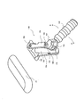
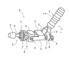
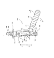
- FIG. 6 is a perspective view of the opening assist mechanism 140 when viewed from below the lower step portion 24. It is a perspective view showing the whole opening auxiliary mechanism 140.
- FIG. 7 is a perspective view showing a state in which a tip end portion 146 of the opening assist mechanism 140 protrudes from the lower step portion 24.
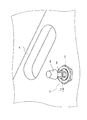
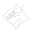
- FIG. FIG. 5 is a perspective view showing a state in which the opening assist mechanism 140 is fixed to the lower step portion 24 of the top plate portion 20. It is the perspective view which looked at the lower step part 24 of the top-plate part 20 from the back surface side (lower surface side).
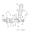
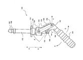
- 7 is a side view showing a state where the opening assist mechanism 140 is operated by the operation lever 144.
- FIG. 7 is a side view showing a state where the opening assist mechanism 140 is operated by the operation lever 144.
- FIG. 7 is a side view showing a state where the opening assist mechanism 140 is operated by the operation lever 144.
- FIG. 7 is a side view showing a state where the opening assist mechanism 140 is operated by the operation lever 144.
- FIG. 5 is a perspective view showing a state in which a tip end portion 146 of the opening assist mechanism 140 protrudes from the
- FIG. 7 is a side view showing a state where the opening assist mechanism 140 is operated by the operation lever 144.
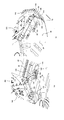
- FIG. It is the expansion perspective view (a) which shows the hinge part 120, and the expansion perspective view (b) which shows the hinge part 120.
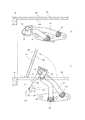
- FIG. 4 is a side view (a) showing the hinge portion 120 in a state where the game board 100 is closed, and a side view (b) showing the hinge portion 120 in a state where the game board 100 is opened to a predetermined angle ⁇ .
- FIG. 3 is a perspective view showing the relationship between the hinge part 120 and the game board 100 when the game board 100 is closed.
- FIG. 3 is a perspective view showing a relationship between the hinge part 120 and the game board 100 when the game board 100 is opened.
- FIG. 3 is a block diagram illustrating configurations of an antenna module 300 and a control unit 510.
- FIG. It is a figure which shows the network structure in game facilities, such as a casino.
- 2 is a block diagram showing a configuration of a server 600.
- FIG. It is a figure which shows the example of a data structure of one record memorize
- the gaming table according to the first embodiment is A gaming board provided with an antenna for reading the identification information stored in the gaming chip by wireless communication;
- a gaming table comprising: a gaming board mounting table on which the gaming board is mounted so as to be openable and closable.
- the gaming board can be opened and closed with respect to the gaming board mounting table, so that the gaming board can be opened without removing the gaming board from the gaming board mounting table, and maintenance of gaming tables such as gaming boards and gaming board mounting tables can be performed. Can be easy.
- the gaming table according to the first embodiment is A game table in which the antenna is provided on the back surface of the game board.
- the antenna provided on the back surface of the game board can be positioned at a desired position such as the height of the line of sight of the worker, and the worker bends Therefore, maintenance can be performed with an easy posture, and the efficiency of maintenance can be improved.
- the gaming table according to the first embodiment is The gaming table further includes an opening / closing connecting device for connecting the gaming board to the gaming board mounting table so as to be opened and closed.
- the opening / closing operation of the gaming board can be made constant.
- the gaming table further includes an opening assist device for changing a state where the game board is closed to a state where a gap is formed between the game board and the game board mounting table.
- the opening assist device can form a gap between the game board and the game board mounting table, an operator such as a store clerk uses the formed gap to, for example, put an operator's hand in the gap.
- the game board can be opened by inserting it, and the work of opening the game board can be facilitated.
- the gaming table further includes an opening / closing braking device that is disposed between the gaming board and the gaming board mounting table and brakes an opening / closing operation of the gaming board.
- the opening and closing of the game board can be braked, and the game board can be prevented from suddenly opening and closing, thereby facilitating maintenance.
- the gaming table further includes an opening / closing auxiliary device that is disposed between the gaming board and the gaming board mounting table and assists the opening / closing operation of the gaming board.
- the gaming board Since the opening and closing of the gaming board can be assisted, the gaming board can be opened and closed without applying a large force to the gaming board, and maintenance can be facilitated by improving workability.
- the gaming table according to the first embodiment is The gaming board has a dealer side where a dealer is located and a player side where a player is located,
- the game board is a game table that can be opened on the player side.
- the game table according to the second embodiment is A plurality of antennas for reading the identification information stored in the gaming chip by wireless communication;
- a plurality of antennas are modularized as an antenna module, when a plurality of antennas are provided on the game table, it is not necessary to provide the antennas separately, and they may be provided on the game table in units of antenna modules. Further, when performing maintenance related to the antenna, it is only necessary to replace the antenna module. Therefore, the matching state of the plurality of antennas in the antenna module can be maintained without individually adjusting the matching state of the plurality of antennas.
- the game table according to the second embodiment is A game board on which game chips are placed in a plurality of game areas corresponding to a plurality of players;
- the antenna module is a game table provided detachably on the game board corresponding to each of the plurality of game areas.
- the antenna module is detachably provided corresponding to each of the plurality of game areas, only the antenna module corresponding to the antenna or the transmission / reception circuit board that needs to be replaced needs to be replaced, and the maintenance of the game table is easy. Can be done.
- the antenna module is An adjustment unit for adjusting the electromagnetic wave output from the antenna; And a through-hole formed at a position corresponding to the position of the adjustment portion.
- the operator can adjust the adjustment unit corresponding to the antenna that needs to be adjusted through a through-hole using a tool such as a screwdriver. Therefore, even when the antenna module has been adjusted in advance and is provided on the game table, adjustment is necessary because a metal conductor exists around the antenna or other parts are attached later.
- the adjustment unit may be adjusted via the through hole, so that the electromagnetic wave output from the antenna can be easily adjusted.
- the game table according to the second embodiment is The gaming board has a dealer side where a dealer is located, and a player side where a plurality of players are located facing the dealer side, The game board can be opened on the player side, The plurality of game areas are game tables arranged along the player side.
- the antenna module is arranged on the game board along the player side corresponding to each of the plurality of game areas. Since the game board can be opened to the player side, when the game board is opened, the player side The antenna module arranged along the line can be positioned at a position where the operator can easily perform work such as the position of the line of sight of the worker, and maintenance can be facilitated.
- the gaming table according to the third embodiment is A registration antenna for validating a gaming chip by reading chip identification information for identifying a gaming chip used in a casino;
- a gaming table comprising: an erasing antenna for reading the chip identification information and invalidating a gaming chip.
- the registration antenna will enable gaming chips, and the erasing antenna will disable gaming chips. For this reason, the gaming chips used in the casino can be processed by being classified into those that have been validated and those that have been invalidated. Therefore, since only the activated gaming chips having a monetary value at the casino can be calculated, the amount can be calculated, so that the balance can be calculated at an arbitrary timing.
- the game table according to the third embodiment is A reference antenna for reading the chip identification information;
- the registration antenna and the erasing antenna are game tables arranged with a reference antenna interposed therebetween.
- the registration antenna and the erasure antenna are placed with the reference antenna in between, so the dealer can clearly recognize the registration antenna and the erasure antenna and prevent human error from occurring Can do. Since the reference antenna reads the chip identification information, the dealer can recognize whether or not the gaming chip is activated.
- the game table according to the third embodiment is It is a game table further provided with an operation switch for putting the reference antenna into an operating state.
- the reference antenna can be operated only when necessary, it is possible to prevent interference of electromagnetic waves by the reference antenna and to speed up reading of other antennas.
- the game table according to the third embodiment is The dealer further includes a chip tray for storing gaming chips,
- the reference antenna is a game table disposed between the chip tray and a player's betting area.
- the dealer can check the valid state with the reference antenna before distributing gaming chips from the chip tray to the player. Before the game chip is stored in the chip tray from the player, the invalid state can be confirmed by the reference antenna, and the occurrence of a human error can be prevented.
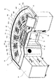
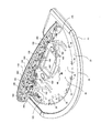
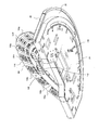
- FIG. 1 is a perspective view of the gaming table (casino table) 10 of the present embodiment as viewed from the dealer side.
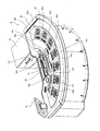
- FIG. 2 is a perspective view of the gaming table 10 according to the present embodiment as viewed from the player side.
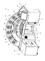
- FIG. 3 is a perspective view of the gaming table 10 with the gaming board opened when viewed from the dealer side.
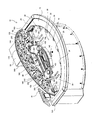
- FIG. 4 is a perspective view of the game table 10 with the game board opened as viewed from the player side.
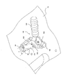
- FIG. 5 is a perspective view showing the inside of the upper side of the top board of the game table when the game board is opened.
- FIG. 6 is a perspective view showing the inside of the lower side of the top of the gaming table when the gaming board is opened.
- the chip tray 80 is omitted.
- FIG. 6 the chip tray 80 is omitted.
- the game table 10 mainly includes a game board 100, a top plate unit 20, a display 70, and a chip tray 80.
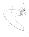
- the game board 100 has a thin plate shape and a substantially fan shape.
- the fan-shaped shape means a shape surrounded by two concentric arcs having different radii and two radii connecting the ends of the two arcs.
- the game board 100 is provided so as to be openable and closable with respect to a top plate portion 20 described later.
- the opening / closing mechanism of the game board 100 will be described later.
- the inner circumference is the dealer side 112 and the outer circumference is the player side 110.
- the gaming board 100 has a thin plate shape and has a front surface 106 and a back surface 108.
- game areas 102a to 102g for seven players and a dealer area 104 are formed on the surface 106 of the gaming board 100.
- the game areas 102a to 102g are areas used by each player.
- the dealer area 104 is an area used by the dealer.
- the game area 102 is referred to as a game area 102 when it is not necessary to distinguish between 102a to 102g.
- the dealer is located on the dealer side 112 and the player is located on the player side 110.
- the dealer and the player face each other across the gaming table 10 and various games such as poker, blackjack, and baccarat are advanced. As the game progresses, cards such as playing cards and gaming chips are dealt or collected at the gaming table 10.
- an antenna module 300 is provided in each of the seven game areas 102a to 102g.
- seven antenna modules 300 are provided along the outer periphery of the game board 100 on the back surface 108 of the game board 100.
- one antenna module 300 'for a reference antenna device 410 to be described later is provided.
- the gaming board 100 is provided with more antenna modules 300 along the outer periphery of the gaming board 100 on the player side 110 than on the dealer side 112.
- the game area 102 In the game area 102, several betting areas are formed.
- the game area 102 is constituted by, for example, a sheet (not shown) on which a betting area is printed.
- the size, shape, and number of betting areas in the game area 102 vary depending on the type of game such as blackjack or baccarat.
- the sheets constituting the game area 102 can be detachably provided on the surface 106 of the game board 100.
- the antenna module 300 is provided with a plurality of antennas 304 according to the betting area.
- the betting area is determined by the type of game.
- the antenna module 300 is provided with a coupler substrate 520. Coupler substrate 520 transmits and receives to / from the RFID IC tag of the gaming chip via antenna 304. Chip information is stored in the RFID IC tag of the gaming chip. The chip information of the gaming chips placed in the betting area is read out by the antenna 304 and the coupler board 520.
- the antenna module 300 is communicably connected to the control unit 510 of the gaming table 10 and the gaming table control device 30 (for example, a personal computer) (not shown). The chip information read by the antenna 304 is transmitted to the game table control device 30 via the control unit 510.
- the configuration and operation of the antenna module 300 will be described later.
- the top plate portion 20 has a substantially semicircular shape.
- the top plate portion 20 has an upper step portion 22 and a lower step portion 24.
- the top board 20 constitutes the upper surface of the game table 10.
- the top plate 20 is fixedly provided on the game table 10. Seven players can be positioned along the substantially arc-shaped outer periphery of the top plate 20. A dealer is located on the front side of the chip tray 80 placed on the top plate 20.
- the upper stage 22 mainly has an area for placing game chips and cards held by the player, and an area for placing a chip tray used by the dealer.
- An opening 26 (see FIG. 4) corresponding to the size and shape of the game board 100 is formed in the upper stage portion 22.
- the lower step portion 24 is disposed below the upper step portion 22.
- the lower stage portion 24 mainly includes a hinge portion 120 and six game board support portions 28 (see FIGS. 4 and 5).
- the hinge part 120 supports the game board 100 so that it can be opened and closed.
- the game board 100 is accommodated in the opening 26, and the game board support unit 28 contacts the back surface 108 of the game board 100 to support the game board 100.
- the accommodation state of the game board 100 is maintained by the hinge part 120 and the game board support part 28.
- the state in which the game board 100 is accommodated in the opening 26 is a normal state in which a game is played on the game table 10.
- the tip part 146 of the opening assist mechanism 140 is disposed in the lower step part 24 (see FIG. 9).
- the opening assist mechanism 140 will be described later.
- the erasing antenna device 400 is provided on the left side of the chip tray 80, the reference antenna device 410 is provided on the back side (player side 110) of the chip tray 80, and the registration antenna device 420 is provided on the right side of the chip tray 80. Is provided. A dealer is located in front of the chip tray 80.
- the three types of erasing antenna device 400, reference antenna device 410, and registration antenna device 420 are arranged so as to surround the chip tray 80 (dealer).
- the erasing antenna device 400 is an antenna for erasing information relating to the player, for example, player identification information for identifying the player.
- the registration antenna device 420 is an antenna for registering player identification information.
- various chip information such as chip identification information for identifying the gaming chip is stored in advance in an RFID IC tag (not shown).
- a game table control device 30 (see FIG. 24) is mounted on the game table 10.
- the gaming table control device 30 is connected via a network 40 so as to be communicable with a server 600 provided in the gaming facility.
- the gaming table control device 30 is connected to the erasing antenna device 400, the reference antenna device 410, the registration antenna device 420, the antenna module 300, and various other sensors.
- the deletion and registration of the player identification information is performed by the game facility server 600 via the game table control device 30 of the game table 10.
- the server 600 manages each gaming chip used in the gaming facility.
- chip identification information for identifying gaming chips and player identification information are associated with each other and stored as a database (a database unit 610 described later).
- the server 600 updates the correspondence between the chip identification information and the player identification information as needed based on various information transmitted from the game table control device 30.
- the chip identification information is read from the gaming chip by the erasing antenna device 400.
- the game table control device 30 of the game table 10 transmits the read chip identification information to the server 600.
- the server 600 deletes the player identification information associated with the received chip identification information from the database. Thereby, the correspondence (linking) between the chip identification information and the player identification information is released, the gaming chip is invalidated, and the gaming chip is returned to the gaming facility from the player.
- the chip identification information is read from the gaming chip by the registration antenna device 420.
- the game table control device 30 of the game table 10 transmits the read chip identification information and the player identification information corresponding to the game chip to the server 600.
- the server 600 receives the chip identification information and the player identification information, and stores the player identification information in association with the chip identification information in the database. As a result, a correspondence (linkage) between the chip identification information and the player identification information is formed, the gaming chip is validated, and the gaming chip is lent to the player from the gaming facility.
- the reference antenna device 410 is an antenna for a dealer to check a gaming chip.
- the dealer distributes gaming chips to the player, it is necessary to take out the gaming chips from the chip tray 80 and perform registration processing, and then distribute gaming chips to the player. At this time, the dealer can check with the reference antenna device 410 whether or not the game chip has been registered before distributing the game chip to the player.
- the dealer when collecting the gaming chips from the player, the dealer needs to erase the processing chips and store the gaming chips in the chip tray 80. At this time, the dealer can confirm whether or not the gaming chip has been erased by the reference antenna device 410 before storing the gaming chip in the chip tray 80.
- the method of checking the gaming chip differs depending on whether not only the chip identification information but also the validation / invalidation information is stored in the gaming chip.
- the reference antenna device 410 reads both the chip identification information and the validation / invalidation information from the gaming chip.
- the game table control device 30 displays the read chip identification information and validation / invalidation information on the display 70.
- the dealer can visually check the chip identification information and the validation / invalidation information displayed on the display 70 to confirm the contents and state of the gaming chips.
- the validation / invalidation information is also stored in the gaming chip, the validation / invalidation information can be displayed on the display 70 without communicating with the server 600.
- the invalidation information is stored in advance in the server 600 (see FIGS. 25 and 26 described later), and communicates with the server 600. It is necessary to obtain validation / invalidation information.
- the chip identification information is read from the gaming chip by the reference antenna device 410.
- the game table control device 30 of the game table 10 transmits the read chip identification information to the server 600.
- the server 600 receives the chip identification information, reads the chip information stored as the record 800 (see FIG. 26) stored in the database unit 610, and transmits the chip information to the game table control device 30.
- the game table control device 30 displays the chip information on the display 70. The dealer can visually check the chip information displayed on the display 70 and confirm the contents and state of the gaming chips.
- the gaming table control device 30 not only displays the chip information transmitted from the server 600 on the display 70, but also based on the chip information, the number of gaming chips distributed to the player and the gaming chips collected from the player, Those amounts can also be displayed on the display 70.
- a display 70 is provided at the right end of the gaming table 10 on the dealer side so that the dealer can visually recognize it.
- the display 70 is connected to the game table control device 30 of the game table 10 and the like.
- the game table control device 30 displays various information such as player identification information, validation / invalidation information, other game chip information, and game information.
- the chip tray 80 is provided in front of the dealer side 112.
- the chip tray 80 is configured to be detachable from the game table 10.
- the chip tray 80 accommodates game chips to be distributed to players and game chips collected from the players. When the dealer leaves the gaming table 10, the dealer removes the chip tray 80 and carries the entire chip tray 80.
- the gaming chips accommodated in the chip tray 80 are managed by a gaming facility such as a dealer.
- a display 75 is provided at a position directly in front of the dealer behind the chip tray 80.
- the display 75 mainly displays information related to gaming chips such as gaming chip information read by the reference antenna device 410.
- the chip identification information of the gaming chip read by the reference antenna device 410, the validation / invalidation information of the gaming chip, and the like are displayed on the display 75.
- the reference antenna device 410 but also information on gaming chips read by the erasing antenna device 400 or the registration antenna device 420 may be displayed on the display 75.
- a chip stocker 90 is arranged on the left side of the dealer of the game table 10. That is, the chip stocker 90 is arranged near the erasing antenna device 400. Four casters are provided on the bottom surface of the chip stocker 90. The chip stocker 90 is placed so as to be movable with respect to the game table 10. The chip stocker 90 stores gaming chips used by dealers. As will be described later, all gaming chips stored in the chip stocker 90 are invalidated.
- a safe 95 is disposed at a position on the right side of the gaming table 10 on the right side of the dealer where it is difficult for the player to see. That is, the safe 95 is disposed near the registration antenna device 420.
- the safe 95 can be opened with a predetermined key.
- the safe 95 can store cash for use by the dealer.
- the cash stored in the safe 95 is cash received from the player or cash to be given to the player for fishing.
- the safe 95 is also provided with a device (not shown) for determining the authenticity of the banknote, so that the banknote received from the player can be determined before being stored in the safe 95.
- a device not shown
- the player can exchange cash for gaming chips without going to the cashier, and can continue playing games on the gaming table 10.
- a keyhole 32 is provided below the front side of the game table 10 on the dealer side.
- the lower panel can be removed by inserting and operating a predetermined key in the key hole 32.
- the operation lever 144 can be operated. The operation lever 144 will be described later.
- the three types of erasing antenna device 400, the reference antenna device 410, and the registration antenna device 420 are arranged so as to surround the chip tray 80 (dealer). Specifically, the erasing antenna device 400 and the registration antenna device 420 are arranged at positions separated from each other with the chip tray 80 (dealer) interposed therebetween. Since the erasing antenna device 400 and the registration antenna device 420 are separately provided with the chip tray 80 in between, the erasing antenna device 400 and the registration antenna device 420 can be clearly distinguished from each other. It is possible to prevent the gaming chips from being confused and to make mistakes in the invalidation processing or the validation processing of the gaming chips, and to reduce the occurrence of human errors.
- both the erasing antenna device 400 and the registration antenna device 420 have a circular shape. These shapes and colors may be different. By making the shapes and colors different, the dealer can easily see the difference between the erasing antenna device 400 and the registration antenna device 420, and the dealer can be prevented from misidentifying.
- the reference antenna device 410 is disposed behind the chip tray 80 (dealer) and in front of the player side 110. It can be clearly distinguished from the erasing antenna device 400 and the registration antenna device 420, and the dealer can be prevented from being confused. Further, since the reference antenna device 410 is located closest to the player, the reference antenna device 410 should be checked before the dealer distributes gaming chips to the player or when the dealer receives gaming chips from the player. This makes it possible to simplify the dealer's work.
- the reference antenna device 410 is arranged behind the display 75 and adjacent to the display 75. It is possible to easily compare the actual gaming chip placed on the reference antenna device 410 with the gaming chip information displayed on the display 75, and the confirmation work of the dealer can be facilitated and simplified.
- the reference antenna device 410 is arranged adjacent to a game area where a medium such as a card is placed. By doing in this way, both the dealer and the player can place the gaming chip in an area that is most focused on, and both the dealer and the player can confirm the gaming chip.
- an operation switch (not shown) for bringing the reference antenna device 410 into an operating state may be provided in the gaming table 10.
- the operation switch can be operated by the dealer.
- the operation switch When the operation switch is turned on, the reference antenna device 410 is in an operating state, and when the operation switch is turned off, the reference antenna device 410 is in a non-operating state.
- interference When close to the antenna 304 of the antenna module 300 provided in the betting area, interference may occur between these antennas and the reference antenna device 410. When interference occurs, it is necessary to repeatedly read in order to improve the reading accuracy of the antenna 304 of the antenna module 300, so that the operation becomes slow and may cause the game to be delayed.
- the dealer turns off the operation switch to leave the reference antenna device 410 in an inactive state, and turns on the operation switch to operate the reference antenna device 410 only when the dealer needs it. Put it in a state. By doing so, it is possible to prevent the reference antenna device 410 from affecting the progress of the game.
- the erasing antenna device 400 is located on the chip stocker 90 side (the left side of the dealer).
- the invalidated gaming chip can be easily accommodated not only in the chip tray 80 but also in the chip stocker 90, and the timing at which the invalidated gaming chip is taken out illegally can be reduced.
- An edge portion 60 is formed along the periphery of the top plate portion 20.
- the edge portion 60 has a long shape along the periphery of the top plate portion 20 and a shape protruding upward.
- an LED substrate (not shown) is provided along the longitudinal direction of the edge portion 60.
- the LED substrate is connected to a power source (not shown) and emits blue light.
- An opening 62 is formed along the longitudinal direction of the edge 60 on the side of the edge 60 facing the dealer.
- a transparent plate made of acrylic or the like is provided in the opening 62 along the opening 62. Blue light from the LED substrate travels to the upper stage portion 22 through the translucent plate.
- the upper stage portion 22 can be illuminated by light emitted from the LED substrate. By doing so, it is possible to illuminate gaming chips, playing cards, and the like placed on the upper stage 22 of the gaming board 100 without depending on the lighting of the gaming facility.
- the gaming table 10 includes an opening assist mechanism 140 for opening the gaming board 100 and an opening / closing braking mechanism 180. As described above, since the game board 100 is large and heavy, it is difficult to open the game board 100 and lift it upward. For this reason, the opening assist mechanism 140 and the opening / closing braking mechanism 180 are provided on the game table 10 to facilitate the work.
- the opening assist mechanism 140 mainly includes a reciprocating movable portion 142 that can reciprocate and an operation lever 144 for operating the reciprocating movable portion 142.
- the reciprocating movable part 142 has a tip part 146, a fixed part 148, a main body part 150, and a rectilinear part 152.
- the fixing part 148 has a holding part 170 and a screw forming part 172.
- maintenance part 170 is inserted and hold
- the screw forming portion 172 is formed so that the screw thread circulates.
- a nut 174 is detachably attached to the screw thread. As will be described later, a nut 174 is attached to the screw forming portion 172, and the reciprocating movable portion 142 is fixed to the lower step portion 24 of the top plate portion 20.
- the main body 150 is formed integrally with the fixed portion 148 and supports the rectilinear portion 152 so as to be able to reciprocate.
- the leading end 146 is provided at the first end 166 of the rectilinear portion 152. As described above, the distal end portion 146 moves with respect to the fixed portion 148 and the main body portion 150 together with the rectilinear portion 152.
- the tip 146 has an elastic body such as rubber or resin.
- the leading end 146 can abut on the back surface 108 of the game board 100.
- a through hole (not shown) is formed in the main body 150.
- a rectilinear portion 152 is inserted into the through hole.
- the rectilinear portion 152 is guided and moved linearly by the through hole of the main body 150.
- the rectilinear portion 152 is supported by the fixed portion 148 and the main body portion 150 so as to be reciprocally movable.
- the rectilinear portion 152 can reciprocate linearly with respect to the fixed portion 148 and the main body portion 150, that is, move upward or downward.
- the distal end portion 146 moves in a direction protruding from the lower step portion 24.
- the distal end portion 146 moves in a direction to be stored in the lower step portion 24.
- the opening assist mechanism 140 has two first coupling bodies 154.
- the first end 156 of the first connector 154 is rotatably connected to the main body 150.
- the second end 158 of the first connecting body 154 is rotatably connected to the first end 162 of the second connecting body 160 formed on the operation lever 144.
- the second end 164 of the operation lever 144 is rotatably provided on the second end 168 of the rectilinear portion 152.
- a connecting portion 155 that connects the two first connecting bodies 154 to each other is formed.
- FIG. 10 is a perspective view showing a state in which the opening assist mechanism 140 is fixed to the lower step portion 24 of the top plate portion 20.
- FIG. 11 is a perspective view of the lower step portion 24 of the top plate portion 20 as viewed from the back surface side (lower surface side).
- a concave portion 50 for attaching the opening assist mechanism 140 is formed in the lower step portion 24 of the top plate portion 20.
- the recess 50 includes a through hole 52, a support portion 54, and a storage portion 56.
- the through hole 52 has a substantially cylindrical shape, and the holding portion 170 of the opening assist mechanism 140 is inserted therethrough.
- the support portion 54 is formed so that the thickness is thinner than the thickness of the top plate portion 20.
- the storage part 56 has a substantially rectangular parallelepiped shape.
- the main body 150 is stored in the storage 56.
- the width w (FIG. 10) of the main body 150 is slightly smaller than the width W (FIG. 11) of the storage portion 56.
- the opening assisting mechanism 140 can be attached to the top plate part 20 so as not to occur.
- the main body 150 and the nut 174 are provided so as to sandwich the support portion 54, and the opening assist mechanism 140 is detachably attached to the lower step portion 24.
- the opening assist mechanism 140 can be attached to the top plate portion 20 so that the opening assist mechanism 140 does not rotate.
- the operation lever 144 can be tilted by an operator such as a store clerk. As described above, by removing the lower panel, the operation lever 144 can be operated, and an operator such as a store clerk can operate the operation lever 144.
- FIG. 12 to 15 are diagrams showing the operation of the operation lever 144 and the operation of the distal end portion 146.
- FIG. FIG. 12 is a diagram showing a state in which the distal end portion 146 is most retracted. By gradually rotating the operation lever 144, the distal end portion 146 gradually moves upward (FIGS. 13 and 14). 15 is a view showing a state in which the distal end portion 146 protrudes most.
- the operation lever 144 is further tilted in the direction of the arrow A, whereby the second end 158 of the first coupling body 154 and the first end 162 of the operation lever 144 are at the rightmost end R (see FIG. 13), and then gradually move in the direction of arrow Y opposite to the X direction.
- the angle ⁇ (see FIG. 15) formed by the first connecting body 154 and the second connecting body 160 can be made zero. it can.
- the second end 164 (straight advance portion 152) of the operation lever 144 moves to the highest position, and the tip end portion 146 moves to the most protruding position. Since the angle ⁇ formed by the first connection body 154 and the second connection body 160 is zero, the first connection body 154 and the second connection body 160 are aligned on a straight line.
- the second end 164 of the operation lever 144 is indicated by a broken line as a hide line.
- the three points of the first end 156 of the first connecting body 154, the second end 158 of the first connecting body 154, and the second end 164 of the operation lever 144 are The second end portion 164 of the operation lever 144 is aligned between the first end portion 156 of the first connecting body 154 and the second end portion 158 of the first connecting body 154. And the second end 158 of the first coupling body 154 moves to the lowest position.
- this state can be stabilized by making the position of the second end 158 of the first connecting body 154 the lowest. Therefore, the state in which the distal end portion 146 is protruded can be stably maintained, and the opening assist mechanism 140 can be locked.
- the operation lever 144 is tilted in the direction of the arrow B (see FIG. 7)
- the distal end portion 146 moves in the direction accommodated in the lower step portion 24 together with the rectilinear portion 152.
- the gaming board 100 is accommodated in the opening 26, and the gaming board 100 can be closed.
- the back surface 108 of the game board 100 comes into contact with the six game board support portions 28.
- the player board 110 of the game board 100 is supported by the six game board support portions 28.
- the game board 100 is supported by two hinge portions 120.
- the game board 100 can be stabilized in the closed state by the six game board support portions 28 and the two hinge portions 120.
- the operation lever 144 is for forming a gap between the game board 100 and the upper stage portion 22, and can facilitate the operation of an operator such as a store clerk.
- the opening / closing braking mechanism 180 is a mechanism for facilitating the opening of the game board 100.
- two gas springs 182 can be used as the opening / closing braking mechanism 180.
- the gas spring 182 has a long shape and is configured to be stretchable.
- the gas spring 182 includes a cylinder body 184 and a piston rod (not shown) that can be stored in the cylinder body 184.
- the cylinder body 184 is filled with a gas such as nitrogen gas.
- the gas spring 182 functions as a spring that uses the pressure of the gas filled in the cylinder body 184 as an urging force.
- the first end of the gas spring 182 is rotatably provided on an engaging portion 190 provided on the back surface 108 of the game board 100.
- a second end of the gas spring 182 is rotatably provided at an engaging portion (not shown) provided at the bottom of the game table 10.
- the urging force of the gas spring 182 is applied to the game board 100 in the direction in which the game board 100 opens.
- the gas spring 182 functions as a braking mechanism, and by providing the gas spring 182, the opening operation of the game board 100 can be assisted without the game board 100 being suddenly opened or closed. Further, since the urging force of the gas spring 182 is applied in the direction in which the game board 100 is opened, the gas spring 182 can be opened with a smaller force than when the gas spring 182 is not present. It can be said that it also functions as a mechanism. Therefore, the operator can easily open the game board 100 without applying a large force to the game board 100.
- the posture of the gaming board 100 is almost upright, and the component of the weight of the gaming board 100 toward the gas spring 182 is reduced.
- the gas spring 182 is adjusted so that the gaming board 100 and the gas spring 182 are balanced and the gaming board 100 is stationary when the gaming board 100 is in the most open state. In this way, the open state of the game board 100 can be maintained.
- the gas spring 182 is provided to be extendable between the back surface 108 of the game board 100 and the bottom of the game table 10.
- the expansion / contraction operation of the gas spring 182 functions as an opening / closing braking mechanism and an opening / closing assist mechanism. Since the gas spring 182 functions as an opening / closing braking mechanism, the opening / closing operation of the gaming board 100 is braked, and the operation of the gaming board 100 can be stabilized without the gaming board 100 being suddenly opened or closed.
- the gas spring 182 functions as an opening / closing assist mechanism. That is, a force for opening the game board 100 is always applied to the game board 100 from the gas spring 182.
- the game board 100 since the game board 100 tries to open by the force from the gas spring 182, the game board 100 gradually increases without applying a force to the game board 100 or simply applying a slight force to the game board 100. Can be opened. Further, when the game board 100 is closed, it is not necessary to close the game board 100 little by little while supporting the game board 100, and the game board 100 can be closed only by applying a slight force to the game board 100 in the closing direction. it can. In this way, the opening / closing operation of the gaming board 100 is assisted, and the gaming board 100 can be opened and closed without applying a large force to the gaming board 100, thereby facilitating the work.
- a hinge portion 120 is provided between the game board 100 and the lower step portion 24.
- the gaming board 100 is connected to the lower stage portion 24 of the gaming table 10 via the hinge portion 120 and does not leave the gaming table 10.
- the hinge part 120 By the hinge part 120, the operation from the closed state to the open state of the game board 100 can be regulated to be constant.
- the hinge portion 120 includes a first fixing portion 122 that is fixedly provided on the back surface 108 of the gaming board 100 and a second fixing portion 124 that is fixedly provided on the lower stage portion 24. .
- a first lever 126 and a second lever 128 are provided between the first fixing portion 122 and the second fixing portion 124.
- the first end portion 130 of the first lever 126 is rotatably provided on the first fixing portion 122.
- the second end portion 132 of the first lever 126 is rotatably provided on the second fixing portion 124.
- the first end portion 134 of the second lever 128 is rotatably provided on the first fixing portion 122.
- the second end portion 136 of the second lever 128 is rotatably provided on the second fixing portion 124.
- FIG. 17A is a side view showing the hinge portion 120 in a state where the game board 100 is closed.
- FIG. 17B is a side view showing the hinge portion 120 in a state where the game board 100 is opened to a predetermined angle ⁇ .
- a part of the hinge portion 120 is indicated by a two-dot chain line, and the gaming board 100 is indicated by a broken line.
- the first fixing portion 122 and the second fixing portion 124 are omitted in order to clarify the operation.
- FIG. 18 is a perspective view showing a relationship between the hinge portion 120 and the game board 100 in a state where the game board 100 is closed.
- FIG. 19 is a perspective view showing a relationship between the hinge portion 120 and the game board 100 in a state where the game board 100 is opened.
- the first lever 126 rotates around the second end 132 according to the opening / closing of the game board 100 (see arrow L in FIG. 17B).
- the second lever 128 rotates around the second end 136 according to the opening / closing of the game board 100 (see arrow M in FIG. 17B).
- the position of the rotation center of the first lever 126 and the position of the rotation center of the second lever 128 are different from each other.
- the radius of the first lever 126 is shorter than the radius of the second lever 128.
- the movement trajectory of the first end portion 130 of the first lever 126 and the movement trajectory of the first end portion 134 of the second lever 128 are not concentric, and the first lever 126
- the first lever 126 and the second lever 128 can be rotated while the distance between the first end portion 130 and the first end portion 134 of the second lever 128 is kept constant.
- the first end portion 134 of the second lever 128 is centered on the first end portion 130 of the first lever 126 in accordance with the opening / closing operation of the gaming board 100. It can rotate (see arrow N in FIG. 17B). That is, as shown in FIGS. 17A, 17B, 18 and 19, the first end portion 134 of the second lever 128 relative to the first end portion 130 of the first lever 126 is changed.
- the opening / closing operation of the gaming board 100 can be made constant by the rotation.
- the gaming board 100 is pivotally fixed to the lower step portion 24 by the hinge portion 120 with the first end portion 130 of the first lever 126 as a pivot.
- the gaming board 100 can be opened and closed on the player side 110 and closed on the dealer side 112.
- the game board 100 makes a predetermined angle ⁇ (see FIG. 17B) with respect to the lower stage portion 24.
- the first lever 126 rotates around the second end 132 (see arrow L), and the second lever 128 rotates around the second end 136 (see FIG. (See arrow M).
- the first lever 126 and the second lever 128 rotate, the first end portion 130 of the first lever 126 and the first end portion 134 of the second lever 128 are the top plate portion. Separated from 20 ends.
- the game board 100 is opened so that the end portion of the game board 100 is gradually separated from the end portion of the top plate portion 20, as indicated by an arrow P in FIG.
- the game board 100 opens while gradually shifting from the dealer side 112 toward the player side 110.
- the first lever 126 and the second lever 128 rotate, the first end portion 130 of the first lever 126 and the first end portion 134 of the second lever 128 move upward. Move towards (arrows L and M). For this reason, as shown by the arrow P, the game board 100 is opened so as to rise slightly upward from the top plate portion 20.
- the game board 100 can be moved away from the end of the top board part 20 gradually. For this reason, there is no interference between the gaming board 100 and the top board portion 20 in the process of opening and closing the gaming board 100, and various seats showing the bet area attached to the top board portion 20 are damaged. Can be prevented.
- the gap between the end of the top board 20 and the end of the game board 100 can be reduced with the game board 100 closed. For this reason, it is possible to prevent a gaming chip or the like from entering between the top board 20 and the gaming board 100.
- first lever 126 and the second lever 128 have a shape that protrudes and curves in the clockwise direction.
- the reason why the first lever 126 and the second lever 128 have a shape that protrudes and curves in the clockwise direction, not in the counterclockwise direction, is that the force that opens to the game board if it is curved in the counterclockwise direction. Acts to prevent the first lever 126 and the second lever 128 from rotating clockwise about their axes (second ends 132 and 136), and in some cases a game This is to avoid the problem that the board 100 does not open.
- first lever 126 and the second lever 128 are shaped so as to protrude in the clockwise direction, when the game board is opened, the first lever 126 and the second lever 128 rotate in the clockwise direction with respect to their axes. Can be induced to do.
- the gaming board 100 As described above, in the gaming board 100, more antenna modules 300 are provided on the player side 110 than the dealer side 112 over the outer periphery of the gaming board 100.
- the gaming board 100 can be opened and closed on the player side 110 and closed on the dealer side 112. In this way, the game board 100 can be opened to the player side 110 where many antenna modules 300 are provided, so that it is possible to facilitate the work of attaching a number of antenna modules 300 and performing maintenance. It is possible to prevent the work from becoming complicated.
- the game board 100 can be easily opened by the hinge portion 120, the opening assist mechanism 140, and the opening / closing braking mechanism 180.
- the antenna module 300 provided on the back surface 108 of the game board 100 can be positioned at the height of the operator's line of sight. For this reason, the operator can perform maintenance with an easy posture, and the efficiency of maintenance can be improved.
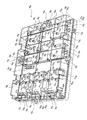
- FIG. 20 is a perspective view of the antenna module 300 viewed from the antenna substrate side.
- FIG. 21 is a perspective view of the antenna module 300 viewed from the coupler substrate side.
- FIG. 22 is a front view of the antenna module 300 as viewed from the coupler substrate side.
- the antenna module 300 has a substantially rectangular parallelepiped shape.
- the housing 302 of the antenna module 300 includes a transparent main body 310 and a transparent lid 350.
- the main body part 310 and the lid part 350 have a substantially rectangular parallelepiped shape.
- the housing 302 of the antenna module 300 is formed by overlapping the main body 310 and the lid body 350.
- Claw portions 314a and 314b are formed on two side surfaces 312a and 312b (not shown) of the main body portion 310, respectively.
- Through holes 354a and 354b are formed in two side surfaces 352a and 352b (not shown) of the lid body portion 350, respectively.
- the main body part 310 can be detachably attached to the lid part 350 by putting the claw part 314a into the through hole 354a and hooking it, and putting the claw part 314b into the through hole 354b and hooking it.
- the main body 310 has a support 320.
- Antenna substrates 330 a to 330 e are arranged on the antenna arrangement surface 322 of the support 320.
- Coupler substrates 520a to 520e are disposed on the circuit board surface 324 of the support 320.
- the coupler substrates 520a to 520e are antenna matching circuits for adjusting the matching state of the antenna 304 formed on the antenna substrates 330a to 330e.
- Each of the antenna boards 330a to 330e has one connector 332 for connecting a cable.
- Each of the coupler boards 520a to 520e has two connectors 522 and 524 for connecting cables.
- the coupler board 520a is electrically connected to the antenna board 330a by connecting the connector 332 of the antenna board 330a and the connector 522 of the coupler board 520a with a cable.
- the coupler substrate 520b is electrically connected to the antenna substrate 330b
- the coupler substrate 520c is electrically connected to the antenna substrate 330c
- the coupler substrate 520d is electrically connected to the antenna substrate 330d.
- a coupler substrate 520e is electrically connected to 330e.
- the antenna substrate 330 when it is not necessary to distinguish the antenna substrates 330a to 330e, they are referred to as the antenna substrate 330.
- coupler substrates 520 when it is not necessary to distinguish between the coupler substrates 520a to 520e, they are referred to as coupler substrates 520.
- the connectors 524 of the coupler boards 520a to 520e are communicably connected to the control unit 510 (see FIG. 23) via cables.
- the control unit 510 is connected to the game table control device 30 (see FIG. 23).
- the antenna board 330 can be driven by the gaming table control device 30 via the control unit 510.
- the antenna module 300 can be attached to the back surface 108 of the game board 100 by inserting a screw into each of the four through holes 356 and screwing the screw into the back surface 108 of the game board 100.
- the antenna module 300 is attached to the back surface 108 of the game board 100 so that the antenna arrangement surface 322 of the support 320 faces the back surface 108 of the game board 100. By doing so, the antenna module 300 can be attached so that the antenna 304 of the antenna boards 330a to 330e is closest to the game board 100.
- Antennas 304 are formed on the surfaces of the antenna substrates 330a to 330e.
- the antenna substrates 330a to 330e are substrates in which a pattern (conductor pattern) of the antenna 304 is formed of a conductive material on a substrate such as a glass epoxy substrate.
- the number, size and shape of the antenna boards 330a to 330e are determined according to the size and shape of the betting area (not shown) in the game areas 102a to 102g determined by the type of game.
- the antenna boards 330a to 330e may be appropriately determined depending on the type of game. In FIG. 20 to FIG. 22, five antenna boards 330a to 330e are shown, but the number may be determined appropriately depending on the type of game such as blackjack or baccarat.
- the controller 510 constitutes a reader / writer control device.
- Control unit 510 is electrically connected to antenna 304 of antenna boards 330a to 330e.
- the control unit 510 can access an RFID IC tag (not shown) provided inside the gaming chip via the antenna 304. Specifically, the control unit 510 reads or writes various chip information stored in the RFID IC tag of the gaming chip by wireless communication using the antenna 304.
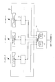
- FIG. 23 is a block diagram showing the configuration of the antenna module 300 and the control unit 510.
- the control unit 510 receives a command issued from the game table control device 30 as a reader / writer control device.
- Control unit 510 accesses the RFID IC tag of the gaming chip in accordance with the received command.
- 23 shows only the antenna 304 (antenna substrate 330) and the adjustment unit 370 as the antenna module 300.
- the antenna module 300 includes the antenna substrate 330 and the antenna substrate 330.
- a coupler substrate 520 Therefore, the antenna module 300 shown in FIG. 23 only needs to include the adjustment unit 370 for adjusting the matching state of the antenna 304.
- the adjustment unit 370 will be described later.
- the control unit 510 reads the chip identification information emitted from the gaming chip. Control unit 510 transmits the read chip identification information to game table control device 30. Control unit 510 is configured by a microcomputer having, for example, a CPU, a ROM, and a RAM (not shown).
- control unit 510 has a function of performing wireless communication with the RFID IC tag of the gaming chip via the antenna 304.
- Control unit 510 includes a modulation unit 512 and a demodulation unit 514.
- Control unit 510 includes, for example, an RF module having a modulation circuit and a demodulation circuit.
- the modulation unit 512 modulates a carrier wave by a predetermined modulation method based on information such as a predetermined command, request, and command received by the control unit 510, generates a modulated wave (modulated signal), and outputs the modulated wave as an RF signal. .
- the output RF signal is supplied to the antenna 304 and emitted from the antenna 304 as an electromagnetic wave.
- the modulated wave received by the antenna 304 is supplied to the demodulator 514 as a modulated signal.
- This modulated wave is an electromagnetic wave in which the carrier wave is modulated by a predetermined modulation method based on the data stored in the RFID IC tag in the gaming chip.
- the demodulator 514 demodulates the modulation signal supplied from the antenna 304, takes out the data stored in the RFID IC tag, and passes it to the controller 510. In this way, the chip identification information stored in the RFID IC tag is passed to the control unit 510.
- control unit 510 transmits and receives electromagnetic waves from the antenna 304 formed on the antenna substrates 330a to 330e, thereby accessing the RFID IC tag of the gaming chip placed in the betting area and accessing it. can do.
- each of the antenna boards 330a to 330e is determined according to the size and shape of the betting area (not shown) of the game area 102.
- the antenna 304 for communicating with the RFID IC tag of the gaming chip is provided in the antenna module 300 as the antenna substrates 330a to 330e. For this reason, in one antenna module 300, some of the five antennas 304 are close to each other. Furthermore, the antenna module 300 is provided in accordance with each of the game areas 102a to 102g. For this reason, the antennas 304 provided in two adjacent antenna modules 300 may be close to each other.
- control unit 510 controls on / off of the antenna 304 of the antenna module 300. Specifically, control unit 510 performs control to simultaneously turn on a plurality of antennas 304 that are separated so as not to cause electromagnetic wave interference so that adjacent antennas 304 are not turned on at the same time. Since control is performed so that a plurality of adjacent antennas 304 are not turned on at the same time, interference can be prevented. In addition, since the plurality of antennas 304 that are spaced apart so as not to cause interference are turned on at the same time, it is possible to quickly communicate by increasing the number of antennas 304 that can communicate simultaneously.
- two control units 510 are provided in the gaming table 10, and each communicates with each other to separately control the on / off of the plurality of antennas 304 provided in the gaming table 10. . By doing so, it is possible to control so that a plurality of adjacent antennas 304 are not simultaneously turned on.
- an electromagnetic wave is output from the antenna 304 to access the RFID IC tag of the gaming chip.
- the electromagnetic wave output from the antenna 304 is greatly affected by various conditions such as intensity, frequency, and spread range.
- the magnetic field formed by the antenna 304 is affected by stray capacitance or noise generated by various metal connection lines (not shown) wired around the game board 100.
- the reading accuracy of the RFID IC tag is affected by the influence of the magnetic field formed by the antenna 304.
- various connection lines there are a power supply wiring for supplying current for exciting the antenna 304, a connection line for connecting the antenna substrate 330 and the coupler substrate 520, and the like. The location and size of the stray capacitance and noise are different depending on the wiring position, the bundling method, and the length of these various connection lines, and the magnetic field formed by the antenna 304 is biased. .
- connection lines are determined to some extent when the game board 100 is designed. Therefore, the sensitivity and strength of the antenna 304 can be adjusted in advance in accordance with the position and length of the connection line.
- the antenna boards 330a to 330e are modularized to form the antenna module 300. For this reason, by modularizing the antenna module 300, if the plurality of antennas 304 are sealed in one antenna module 300 and adjusted in advance in the manufacturing process, the antenna 304 can be easily adjusted during assembly. Can be done. Further, even if the antenna position is moved due to the replacement of the antenna 304 or the change of the type of game to be executed during maintenance, the positional relationship between the plurality of antennas 304 in the antenna module 300 is maintained.
- the coupler substrate 520 is provided with an adjustment unit 370 for adjusting an electromagnetic wave output from the antenna 304.
- the adjustment unit 370 includes a variable resistor that can change the resistance value, a variable capacitor that can change the capacitance, and the like.
- the adjustment unit 370 is not limited to a variable resistor or a variable capacitor, and may be any element that can adjust or switch electromagnetic waves, such as a dip switch, or any element that allows an operator to change various parameters.
- a plurality of through-holes 360 are formed in the lid body 350 in advance for adjustment in the adjustment unit 370.
- An operator such as a store clerk can operate the adjustment unit 370 using an adjustment tool such as a driver through the through hole 360.
- the through hole 360 of the lid portion 350 is formed in the lid portion 350 so as to face the adjustment portion 370 provided in the coupler substrate 520.
- the through-hole 360 is not limited to the case where the through-hole 360 is formed so as to face the adjustment portion 370, and may be formed according to the operation and shape of the adjustment tool used for adjustment.
- the adjustment unit 370 can be operated in the state of the antenna module 300, and the electromagnetic wave output from the antenna 304 can be adjusted. Further, the adjustment unit 370 can be operated without removing the lid 350 from the main body 310.
- the electromagnetic wave output from the antenna 304 can be adjusted in advance. Further, even after the antenna module 300 is attached to the game board 100, it may be necessary to make adjustments for optimizing the intensity or frequency of the electromagnetic wave output from the antenna 304. Even in such a case, the adjustment unit 370 can be adjusted without removing the antenna module 300 from the game board 100.
- the antenna module 300 is provided in accordance with each of the game areas 102a to 102g.
- an antenna module 300 ′ (not shown) is provided for each of the erasing antenna device 400, the reference antenna device 410, and the registration antenna device 420.
- the antenna module 300 ′ has the same configuration as the antenna module 300, and includes an antenna substrate 330 ′ and a coupler substrate 520 corresponding to the shape and size of the erasing antenna device 400, the reference antenna device 410, and the registration antenna device 420. Have '.
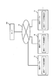
- FIG. 24 is a diagram showing a network configuration in a gaming facility such as a casino.
- the server 600 and the plurality of gaming tables 10 are communicably connected via the network 40.
- the game table control device 30 is mounted on the game table 10, and the game table control device 30 communicates with the server 600 via the network 40.
- a cashier (not shown) is connected to the server 600 via the network 40 in addition to the gaming table 10.
- FIG. 25 is a block diagram showing a configuration of the server 600.
- the server 600 mainly includes a database unit 610, a transmission / reception unit 620, a settlement processing unit 630, and an validation / invalidation processing unit 640.
- the server 600 is mainly configured by a computer having a CPU (Central Processing Unit), a ROM (Read Only Memory), a RAM (Random Access Memory), an HDD (Hard Disk Drive), and a communication interface (each not shown).
- the These CPU, ROM, RAM, HDD, communication interface, and the like constitute a database unit 610, a transmission / reception unit 620, a settlement processing unit 630, and an validation / invalidation processing unit 640.
- the database unit 610 stores various chip information of each gaming chip in association with the chip identification information.
- the database unit 610 has one record for one gaming chip.
- FIG. 26 is a diagram illustrating an example of a data configuration of one record 800 stored in the database unit 610.
- the record 800 includes a chip identification information field 801, a business location identification information field 802, a display surface amount field 803, a chip status information field 804, a chip owner field 805, a valid / invalid status field 806, and a latest valid It has an invalidation date / time field 807, an activated device information field 808, a latest invalidation date / time field 809, and an invalidated device information field 810.
- chip identification information field 801 chip identification information stored in the RFID IC tag of the gaming chip is stored.
- the business location identification information field 802 stores information for identifying a gaming facility, a hotel, or the like where the gaming chip is used.
- the display surface amount field 803 stores the value of the display amount of the gaming chip. For example, “10” is stored if the monetary value of the gaming chip is $ 10, and “100” is stored if it is $ 100.
- the chip status information field 804 stores information indicating the accounting status of the gaming chip. For example, information indicating that it has been given to the player by exchanging for cash, information indicating that it has been distributed as a dividend to the player, information indicating that it has been collected from the player, or that it has been converted into cash Information and the like are stored in the chip state information field 804.
- the server 600 stores in the chip status information field 804 information indicating that it has been delivered to the player by exchanging for cash. Further, when the player wins the game, information indicating that the player has been distributed as a dividend in the server 600 based on reading the chip identification information from the registration antenna device 420 from the gaming chip. It is stored in the status information field 804. Further, when the player loses the game, based on the fact that the chip identification information is read from the gaming chip from the erasing antenna device 400, information indicating that the server 600 has collected it from the player is chip state information. Stored in field 804. Further, when the player returns the gaming chip in exchange for cash at the cashier, information indicating that the cash has been converted into cash is stored in the chip status information field 804.
- the chip owner field 805 stores information indicating the owner of the gaming chip, such as player identification information.
- validation / invalidation information indicating whether the gaming chip is valid or invalid is stored.
- the validation / invalidation information is information indicating that the gaming chip is validated or information indicating that the gaming chip is invalidated.
- all gaming chips used in the gaming facility are validated or invalidated.
- an activated gaming chip has a monetary value at a gaming facility and is allowed to be cashed at a cashier or used for payment instead of cash at a store such as a restaurant.
- the invalidated gaming chip has no monetary value at the gaming facility and cannot be used at the gaming facility.
- the server 600 manages the activation and invalidation of gaming chips. More specifically, the validation / invalidation information stored in the valid / invalid state field 806 manages the validation and invalidation of all gaming chips used in the gaming facility. When a gaming chip is lent to a player, the gaming chip is activated. On the other hand, when the gaming chip is not lent to the player, the gaming chip is invalidated. Note that this does not apply to cases where the player holds a gaming chip that has been invalidated due to fraud.
- the gaming chips When renting gaming chips to a player, the gaming chips are validated because they have a monetary value. If all of these activated gaming chips are discriminated and the monetary value is calculated, the settlement at the gaming facility at that time can be settled. Therefore, by activating the gaming chip, the settlement process can be executed even in a gaming facility such as a casino that is open for 24 hours.
- the dealer gives game chips corresponding to the payout to the player.
- the dealer takes out the invalid gaming chip from the chip tray 80 in accordance with the payout, validates the taken gaming chip using the registration antenna device 420, and passes it to the player.
- the gaming table control device 30 of the gaming table 10 reads the chip identification information and the game
- the player identification information indicating the player who passes the chip for use is transmitted to the server 600.
- the server 600 receives the chip identification information and the player identification information, stores the activation information indicating that it is activated in the valid / invalid state field 806, and stores the player identification information in the chip owner field 805.
- the chip state information field 804 information indicating that the player has been distributed as a payout is stored.
- the dealer collects gaming chips placed in the betting area. At this time, the dealer first collects the gaming chips placed in the betting area, invalidates the collected gaming chips using the erasing antenna device 400, and stores them in the chip tray 80.
- the gaming table control device 30 of the gaming table 10 transmits the read chip identification information to the server 600.
- the server 600 receives the chip identification information, stores invalidation information indicating invalidation in the valid / invalid state field 806, and deletes the player identification information stored in the chip owner field 805.
- the chip status information field 804 stores information indicating that it has been collected from the player. Thereby, the correspondence relationship (linking) between the chip identification information and the player identification information is released, the collected gaming chips are invalidated, and the gaming chips are returned to the gaming facility from the player It becomes. As a result, the monetary value of the gaming chip disappears.
- the player receives gaming chips in exchange for cash at the cashier.
- the cashier takes out the invalidated gaming chip from a storage such as a safe in accordance with cash, validates the taken gaming chip using the registration antenna device 420, and passes it to the player.
- the registration antenna device 420 installed in the cashier also has the same configuration as the registration antenna device 420 of the game table 10.
- the cashier's chip reading device (not shown)
- the player identification information indicating the player who passes the gaming chip is transmitted to the server 600.
- the server 600 receives the chip identification information and the player identification information, stores the activation information indicating that it is activated in the valid / invalid state field 806, and stores the player identification information in the chip owner field 805.
- the chip state information field 804 information indicating that it has been delivered to the player by exchange with cash is stored.
- the player may exchange gaming chips for cash at the cashier.
- the cashier uses the erasing antenna device 400 to check whether the gaming chip received from the player is valid.
- the chip reading device of the cashier transmits the chip identification information read using the erasing antenna device 400 to the server 600.
- the server 600 receives the chip identification information, reads the validation / invalidation information in the valid / invalid state field 806, and transmits it to the cashier's chip reader.
- the cashier can confirm whether or not the gaming chip is valid based on the validation / invalidation information transmitted from the server 600. Only when the gaming chip received from the player is valid, the player can convert the gaming chip into cash.
- the erasing antenna device 400 installed in the cashier also has the same configuration as the erasing antenna device 400 of the game table 10.
- the cashier's chip reading device transmits the chip identification information read using the erasing antenna device 400 to the server 600.
- the server 600 receives the chip identification information, stores invalidation information indicating invalidation in the valid / invalid state field 806, and deletes the player identification information stored in the chip owner field 805.
- the chip state information field 804 stores information indicating that it has been converted into cash. As a result, the correspondence (linking) between the chip identification information and the player identification information is released, the gaming chip received from the player is invalidated, and the gaming chip is returned to the gaming facility from the player. It becomes a state. As a result, the monetary value of the gaming chip disappears.
- the invalidated gaming chips are stored in a storage such as a safe.
- Enabled gaming chips have a monetary value and are allowed to be exchanged at cashiers or used for payment instead of cash at stores such as restaurants. On the other hand, invalidated gaming chips have no monetary value and cannot be used in gaming facilities.
- the most recent activation date / time field 807 stores the date / time when the gaming chip was last activated.
- the validating device information field 808 stores information for identifying the device that has read the RFID IC tag of the gaming chip when the gaming chip is last validated.
- the latest invalidation date / time field 809 stores the date / time when the gaming chip was last invalidated.
- the invalidation device information field 810 stores information for specifying the device that has read the RFID IC tag of the gaming chip when the gaming chip is last invalidated.
- the transmission / reception unit 620 transmits / receives various data between the game table 10 and the cashier. For example, an inquiry signal indicating whether the gaming chip from which the chip identification information has been read by the reference antenna device 410 has been validated or invalidated is sent from the gaming table control device 30 of the gaming table 10 to the server 600. Sent to. When the transmission / reception unit 620 receives this inquiry signal, the server 600 refers to the database unit 610 and searches the chip identification information field 801 in which the chip identification information of the game chip inquired is stored. The validation / invalidation information is read from the validation / invalidity state field 806 of the record 800 with the matching chip identification information. Next, the server 600 transmits the validation / invalidation information to the game table control device 30 of the game table 10.
- an inquiry signal indicating whether the gaming chip from which the chip identification information has been read by the reference antenna device 410 has been validated or invalidated is sent from the gaming table control device 30 of the gaming table 10 to the server 600. Sent to.
- the server 600 refer
- the game table control device 30 of the game table 10 displays the validation / invalidation information transmitted from the server 600 on the display 70.
- the dealer of the gaming table 10 visually recognizes the invalidation / invalidation information displayed on the display 70, and the gaming chip whose chip identification information has been read by the reference antenna device 410 is suitable as a gaming chip to be distributed to the player. It can be confirmed whether or not it is suitable as a gaming chip to be collected in the chip tray 80.
- the server 600 when the chip identification information is read by the reference antenna device 410, an inquiry signal is transmitted to the server 600, and the server 600 validates / invalidates from the valid / invalid state field 806 according to the chip identification information. Information is read. Therefore, when the chip identification information is read by the reference antenna device 410, the server 600 does not update various information.
- the settlement processing unit 630 refers to the database unit 610 at a predetermined timing, searches the valid / invalid state field 806 for all gaming chips registered in the database unit 610, and all the activated chips are validated. The gaming chips and all the invalidated gaming chips are extracted. Since the extracted gaming chips are all gaming chips that are activated at that time, they are all gaming chips having a monetary value. The settlement processing unit 630 reads the value of the display amount of the gaming chip from the display surface amount field 803 for all the activated gaming chips, and executes the settlement processing at that timing.
- the validation / invalidation processing unit 640 updates the player identification information and the validation / invalidation information. Specifically, when the chip identification information read by the registration antenna device 420 is transmitted from the game table 10 together with the player identification information, the validation / invalidation processing unit 640 searches the chip identification information field 801. Thus, the record 800 that matches the transmitted chip identification information is searched. Next, the player identification information is stored in the chip owner field 805 of the record 800 in which the chip identification information matches, and information indicating that it is enabled is stored in the valid / invalid state field 806 as validation / invalidation information. To do. By doing so, a correspondence relationship (linking) between the chip identification information and the player identification information is formed.
- the validation / invalidation processing unit 640 searches the chip identification information field 801 and transmits the transmitted chip identification information. Look for a record 800 that matches the information. Next, the player identification information stored in the chip owner field 805 of the record 800 in which the chip identification information matches is deleted, and information indicating that the chip identification information is invalidated is validated / invalidated as validation invalidation information. Store in field 806. By doing so, the correspondence (linking) between the chip identification information and the player identification information is released.
- the validation / invalidation information is stored in the validation / invalid state field 806 of the server 600 in the case where the validation / invalidation information is stored in the validation / invalid state field 806 of the server 600 has been described.
- the validation / invalidation information is stored in the RFID IC tag of the gaming chip in a readable / writable manner. Also good. With this configuration, it is possible to read and write the validation / invalidation information without communicating with the server 600, and determine whether the gaming chip is validated or invalidated. can do.
- the value of the display amount of the gaming chip is stored in the display surface amount field 803 of the server 600 , but the value of the display amount of the gaming chip is the RFID IC of the gaming chip. It may be stored in a tag. With this configuration, it is possible to read the value of the display amount of the gaming chip without communicating with the server 600.
- gaming table 20 top plate (game board mounting table) 100 gaming board 120 hinge part (opening and closing connecting device) 140 Opening assistance mechanism (opening assistance device) 180 Open / close braking mechanism (open / close braking device) 300 Antenna module 304 Antenna 600 Server
Landscapes
- Physics & Mathematics (AREA)
- General Physics & Mathematics (AREA)
- Engineering & Computer Science (AREA)
- Multimedia (AREA)
- Support Of Aerials (AREA)
- Pinball Game Machines (AREA)
- Slot Machines And Peripheral Devices (AREA)
Abstract
Priority Applications (6)
| Application Number | Priority Date | Filing Date | Title |
|---|---|---|---|
| US15/111,934 US10258868B2 (en) | 2014-01-29 | 2015-01-06 | Game table |
| PH12016501510A PH12016501510A1 (en) | 2014-01-29 | 2016-07-29 | Game table |
| US16/270,165 US10702765B2 (en) | 2014-01-29 | 2019-02-07 | Game table |
| US16/270,104 US10702764B2 (en) | 2014-01-29 | 2019-02-07 | Game table |
| PH12019500311A PH12019500311A1 (en) | 2014-01-29 | 2019-02-13 | Game table |
| PH12019500310A PH12019500310A1 (en) | 2014-01-29 | 2019-02-13 | Game table |
Applications Claiming Priority (6)
| Application Number | Priority Date | Filing Date | Title |
|---|---|---|---|
| JP2014-014852 | 2014-01-29 | ||
| JP2014-014853 | 2014-01-29 | ||
| JP2014014853A JP5898707B2 (ja) | 2014-01-29 | 2014-01-29 | 遊技テーブル |
| JP2014014854A JP5937119B2 (ja) | 2014-01-29 | 2014-01-29 | 遊技システムおよび遊技テーブル |
| JP2014014852A JP5957020B2 (ja) | 2014-01-29 | 2014-01-29 | 遊技テーブル |
| JP2014-014854 | 2014-01-29 |
Related Child Applications (3)
| Application Number | Title | Priority Date | Filing Date |
|---|---|---|---|
| US15/111,934 A-371-Of-International US10258868B2 (en) | 2014-01-29 | 2015-01-06 | Game table |
| US16/270,104 Continuation US10702764B2 (en) | 2014-01-29 | 2019-02-07 | Game table |
| US16/270,165 Continuation US10702765B2 (en) | 2014-01-29 | 2019-02-07 | Game table |
Publications (1)
| Publication Number | Publication Date |
|---|---|
| WO2015115123A1 true WO2015115123A1 (fr) | 2015-08-06 |
Family
ID=53756701
Family Applications (1)
| Application Number | Title | Priority Date | Filing Date |
|---|---|---|---|
| PCT/JP2015/050104 Ceased WO2015115123A1 (fr) | 2014-01-29 | 2015-01-06 | Table de jeu |
Country Status (3)
| Country | Link |
|---|---|
| US (3) | US10258868B2 (fr) |
| PH (3) | PH12016501510A1 (fr) |
| WO (1) | WO2015115123A1 (fr) |
Families Citing this family (5)
| Publication number | Priority date | Publication date | Assignee | Title |
|---|---|---|---|---|
| KR102712890B1 (ko) * | 2019-01-31 | 2024-10-04 | 엔제루 구루푸 가부시키가이샤 | 관리 시스템 |
| USD932557S1 (en) * | 2019-02-20 | 2021-10-05 | Brian M Sarne | Game table |
| US11183031B2 (en) * | 2020-02-21 | 2021-11-23 | Ten Stix Gaming, Inc. | Blackjack side game and blackjack table surface |
| US20230245514A1 (en) * | 2022-01-19 | 2023-08-03 | Jose Luis Osuna Valerio | Cash box holding system |
| KR20230117662A (ko) * | 2022-02-01 | 2023-08-08 | 엔제루 구루푸 가부시키가이샤 | 관리 시스템 |
Citations (4)
| Publication number | Priority date | Publication date | Assignee | Title |
|---|---|---|---|---|
| JP2005111223A (ja) * | 2003-10-09 | 2005-04-28 | Aisin Kiko Co Ltd | 遊技機 |
| JP2012075781A (ja) * | 2010-10-05 | 2012-04-19 | Universal Entertainment Corp | 遊技テーブル装置 |
| US20130207345A1 (en) * | 2010-02-21 | 2013-08-15 | Gaming Partners International Usa | Gaming tables having a table top exchangeable insert |
| JP2013222237A (ja) * | 2012-04-13 | 2013-10-28 | Universal Entertainment Corp | 識別情報アクセス装置 |
Family Cites Families (17)
| Publication number | Priority date | Publication date | Assignee | Title |
|---|---|---|---|---|
| US3188158A (en) * | 1965-06-08 | Oscoz sanchez folding table | ||
| US2102449A (en) * | 1937-01-21 | 1937-12-14 | Zimmerman Leo | Combination table |
| US2827352A (en) * | 1955-06-29 | 1958-03-18 | Misak K Boyajian | Combination folding picnic and game table and carrying case for folding chairs and other appliances |
| US3227105A (en) * | 1964-11-27 | 1966-01-04 | Reisdorff Robert | Table |
| US3899178A (en) * | 1974-04-22 | 1975-08-12 | Hideo Watanabe | Automatic game block shuffling, aligning and table top arraying machine |
| US4838179A (en) * | 1988-03-21 | 1989-06-13 | Bing Ting S | Portable collapsible game table |
| US5556094A (en) * | 1995-06-26 | 1996-09-17 | Shiledar Baxi; Hari R. | Hockey-type game |
| US6267671B1 (en) * | 1999-02-12 | 2001-07-31 | Mikohn Gaming Corporation | Game table player comp rating system and method therefor |
| US6419224B1 (en) * | 2001-03-30 | 2002-07-16 | Lore Tsai | Complex multifunctional game table structure |
| US6766747B1 (en) * | 2003-05-27 | 2004-07-27 | John P. Wolfe | Game table with recessed game board storage area |
| US7156396B1 (en) * | 2004-06-23 | 2007-01-02 | Voden Justin L | Collapsible game table |
| US7575240B1 (en) * | 2005-04-01 | 2009-08-18 | Voden Justin L | Collapsible game table |
| US20070057469A1 (en) * | 2005-09-09 | 2007-03-15 | Shuffle Master, Inc. | Gaming table activity sensing and communication matrix |
| EP1961464B1 (fr) * | 2005-10-25 | 2013-03-20 | Aleksandr Dmitrievich Zhukov | Procédé de jeu d'échecs et dispositif destiné à sa réalisation |
| US7637827B2 (en) * | 2006-02-13 | 2009-12-29 | Vern William Bangerter | Table tennis game having a playing surface divided into multiple independent playing stations by intersecting rigid barriers |
| TW201200070A (en) * | 2010-02-21 | 2012-01-01 | Gaming Partners International Inc | Gaming table protecting antennas from electromagnetic interferences |
| US9299222B2 (en) * | 2011-09-30 | 2016-03-29 | Fortis, LLC | Real-time tracking of locations of machine-readable Pai Gow gaming tiles |
-
2015
- 2015-01-06 WO PCT/JP2015/050104 patent/WO2015115123A1/fr not_active Ceased
- 2015-01-06 US US15/111,934 patent/US10258868B2/en active Active
-
2016
- 2016-07-29 PH PH12016501510A patent/PH12016501510A1/en unknown
-
2019
- 2019-02-07 US US16/270,104 patent/US10702764B2/en active Active
- 2019-02-07 US US16/270,165 patent/US10702765B2/en active Active
- 2019-02-13 PH PH12019500311A patent/PH12019500311A1/en unknown
- 2019-02-13 PH PH12019500310A patent/PH12019500310A1/en unknown
Patent Citations (4)
| Publication number | Priority date | Publication date | Assignee | Title |
|---|---|---|---|---|
| JP2005111223A (ja) * | 2003-10-09 | 2005-04-28 | Aisin Kiko Co Ltd | 遊技機 |
| US20130207345A1 (en) * | 2010-02-21 | 2013-08-15 | Gaming Partners International Usa | Gaming tables having a table top exchangeable insert |
| JP2012075781A (ja) * | 2010-10-05 | 2012-04-19 | Universal Entertainment Corp | 遊技テーブル装置 |
| JP2013222237A (ja) * | 2012-04-13 | 2013-10-28 | Universal Entertainment Corp | 識別情報アクセス装置 |
Also Published As
| Publication number | Publication date |
|---|---|
| US20160346669A1 (en) | 2016-12-01 |
| US10702764B2 (en) | 2020-07-07 |
| US10258868B2 (en) | 2019-04-16 |
| PH12019500311A1 (en) | 2019-11-11 |
| US20190168109A1 (en) | 2019-06-06 |
| PH12016501510B1 (en) | 2017-02-06 |
| US20190168108A1 (en) | 2019-06-06 |
| PH12019500310A1 (en) | 2019-11-11 |
| PH12016501510A1 (en) | 2017-02-06 |
| US10702765B2 (en) | 2020-07-07 |
Similar Documents
| Publication | Publication Date | Title |
|---|---|---|
| US10702764B2 (en) | Game table | |
| US8690678B2 (en) | Shape control of magentic fields for table games | |
| US9378615B2 (en) | Gaming table device having a game table on which the game medium is disposed | |
| US9821221B2 (en) | Gesture enhanced input device | |
| US8992323B2 (en) | Gesture enhanced input device | |
| US8262475B2 (en) | Chipless table split screen feature | |
| US9697687B2 (en) | Gaming system with casino chip tracking | |
| US6923724B2 (en) | Gaming system allowing location determination of a gaming unit in a casino | |
| AU2010318585B2 (en) | Gesture enhanced input device | |
| US20130217491A1 (en) | Virtual button deck with sensory feedback | |
| JP5957020B2 (ja) | 遊技テーブル | |
| JP6063490B2 (ja) | 遊技媒体収納体 | |
| JP5937119B2 (ja) | 遊技システムおよび遊技テーブル | |
| US20090191933A1 (en) | Table with sensors and smart card holder for automated gaming system and gaming cards | |
| WO2017143313A1 (fr) | Systèmes et procédés d'utilisation de données capturées par des composants détecteurs d'un système de table activée par rfid | |
| US20120105215A1 (en) | Portable reader | |
| JP5898707B2 (ja) | 遊技テーブル | |
| EP2285458A2 (fr) | Table avec indicateurs et support de cartes intelligent pour système de jeux automatisé et cartes de jeu | |
| US20050212203A1 (en) | Note validating and storage assembly and method | |
| JP6097330B2 (ja) | 遊技媒体交換装置 |
Legal Events
| Date | Code | Title | Description |
|---|---|---|---|
| 121 | Ep: the epo has been informed by wipo that ep was designated in this application |
Ref document number: 15743332 Country of ref document: EP Kind code of ref document: A1 |
|
| WWE | Wipo information: entry into national phase |
Ref document number: 15111934 Country of ref document: US |
|
| NENP | Non-entry into the national phase |
Ref country code: DE |
|
| WWE | Wipo information: entry into national phase |
Ref document number: 12016501510 Country of ref document: PH |
|
| 122 | Ep: pct application non-entry in european phase |
Ref document number: 15743332 Country of ref document: EP Kind code of ref document: A1 |
|
| WWE | Wipo information: entry into national phase |
Ref document number: 12024553121 Country of ref document: PH |