WO2015115357A1 - Dispositif de transfert - Google Patents
Dispositif de transfert Download PDFInfo
- Publication number
- WO2015115357A1 WO2015115357A1 PCT/JP2015/051993 JP2015051993W WO2015115357A1 WO 2015115357 A1 WO2015115357 A1 WO 2015115357A1 JP 2015051993 W JP2015051993 W JP 2015051993W WO 2015115357 A1 WO2015115357 A1 WO 2015115357A1
- Authority
- WO
- WIPO (PCT)
- Prior art keywords
- transport
- unit
- conveyor
- sub
- main
- Prior art date
- Legal status (The legal status is an assumption and is not a legal conclusion. Google has not performed a legal analysis and makes no representation as to the accuracy of the status listed.)
- Ceased
Links
Images












Classifications
-
- B—PERFORMING OPERATIONS; TRANSPORTING
- B65—CONVEYING; PACKING; STORING; HANDLING THIN OR FILAMENTARY MATERIAL
- B65G—TRANSPORT OR STORAGE DEVICES, e.g. CONVEYORS FOR LOADING OR TIPPING, SHOP CONVEYOR SYSTEMS OR PNEUMATIC TUBE CONVEYORS
- B65G47/00—Article or material-handling devices associated with conveyors; Methods employing such devices
- B65G47/52—Devices for transferring articles or materials between conveyors i.e. discharging or feeding devices
- B65G47/53—Devices for transferring articles or materials between conveyors i.e. discharging or feeding devices between conveyors which cross one another
- B65G47/54—Devices for transferring articles or materials between conveyors i.e. discharging or feeding devices between conveyors which cross one another at least one of which is a roller-way
Definitions
- the present invention relates to a transfer device that constitutes a part of a conveyor line, and more particularly, to a transfer device that can change the conveyance direction of a conveyed product to a direction that intersects the loading direction.
- a conveyor line In the assembly line of products and the delivery place for goods, a conveyor line is often used for transporting transported items.
- a large number of conveyor lines are installed vertically and horizontally in a delivery area, and a transfer device is arranged at a position where the conveyor lines intersect.
- the transfer device has a function of carrying out articles from an original conveyor line (main conveyor line), transferring them to another conveyor line (sub-conveyor line), and transporting them to a desired place.
- the transfer device is provided with two transport conveyor parts for transporting articles and lifting means for changing the height position of the transport conveyor part in order to perform the above-described functions.
- Each of the two transport conveyor units has a transport path for placing and transporting a transported object.
- the transport paths of the two transport conveyor units have different transport directions.
- the transfer device has a configuration in which the relative height of the two conveyance paths can be changed by the above-described lifting means.
- This type of transfer device uses a lifting means to retract the top surface of the transport path of the transport conveyor unit on the side not related to transport below the transport surface of the conveyor line, and further to the transport conveyor unit on the side that contributes to transport The top surface is lifted and exposed to the conveyor surface side of the conveyor line. Then, by operating (running) the transport conveyor unit on the side lifted to the transport surface side, smooth transport is possible without being disturbed by the transport unit not related to transport.
- the transfer apparatus is provided with the control means for raising / lowering two conveyance conveyor parts each straightly.
- the restricting means is a linear guide, and is constituted by a pin or shaft in an upright posture and a bearing member that engages with the pin or shaft and slides the pin.
- Patent Document 1 discloses a multistage conveyor device that conveys a conveyed product by stacking conveyor devices in multiple stages in the vertical direction.
- the prior art transfer device is unsatisfactory in that its overall height is higher than other parts of the conveyor line. That is, as described above, the transfer device constitutes a part of the conveyor line.
- the conventional transfer device has a high overall height, and the height of the entire conveyor line is unsatisfactory.
- the overall height of the conveyor line is determined by the transfer device portion. For example, if the part (main part) other than the transfer device of the conveyor line is a roller conveyor, the height of the main part can be suppressed to a level slightly higher than the outer diameter of the roller even in the prior art.
- the total height can be suppressed to be slightly higher than the outer diameters of the pulleys at both ends even in the prior art.
- the total height of the transfer device of the prior art is higher than that of the mainstream conveyor. For this reason, it has been difficult to install a conventional transfer device on a part of a multi-stage conveyor device as disclosed in Patent Document 2.
- the present invention focuses on the above-mentioned problems of the prior art, and an object of the present invention is to develop a transfer device capable of reducing the overall height as compared with the prior art.
- An aspect for solving the above-described problem includes a main transport unit, a sub transport unit, and an elevating unit, and the elevating unit elevates and lowers at least one of the main transport unit or the sub transport unit, and A motor for operating the lifting mechanism, the main transport unit is provided with a plurality of main transport bodies that rotate or run in contact with the transported object and send the transported object in a certain direction, and the sub transport unit has a transported object.
- a plurality of sub-carriers that rotate or run in contact with the conveyance object and send the object to be conveyed in a direction intersecting the conveyance direction of the main conveyance unit are provided, and the main conveyance unit and the sub-conveyance unit are in the same plane area
- the planar layout position of the motor is It is a planar area that overlaps the main transport unit and the sub transport unit.
- the arrangement position in the height direction of the motor is such that a part or the whole of the motor is above the height of the lower end of the rotation trajectory or the travel trajectory of any of the transport bodies when any of the transport units is lowered. It is a transfer device characterized by the position.
- the planar arrangement position of the motor is a planar region overlapping the main transport unit and the sub transport unit, so the area occupied by the transfer device is small. Further, the arrangement position in the height direction of the motor is such that a part or the whole of the motor is above the height of the lower end of the rotation locus or travel locus of any one of the conveyance bodies in a state where any conveyance unit is lowered. Position. Therefore, the height of the transfer device is extremely low, and the overall height of the transfer device can be designed to be low.
- the transport body of one transport unit is a roller or a rotating body composed of small rotary bodies arranged coaxially, and the transport body of the other transport unit is a narrow constriction conveyor,
- the rotating bodies are arranged in parallel with a certain interval, and the constriction conveyor is located between the rotating bodies and protrudes between the rotating bodies, and the arrangement position of a part or the whole of the motor in the height direction is the rotating body.
- This is a transfer apparatus characterized in that it is above the height of the lowest end of the belt and above the height of the lower end of the rotation locus or travel locus of the constriction conveyor.
- the transport body of one transport unit is a rotating body composed of rollers or small rotating body groups arranged coaxially, and the other transport unit is a narrow constriction conveyor, and the rotation
- the bodies are arranged in parallel at regular intervals, and the constriction conveyor is between the rotating bodies and protrudes from and between the rotating bodies.
- the position of the motor in part or in the whole in the height direction is higher than the lowest end of the rotating body, and higher than the lower end of the narrowing conveyor rotation locus or traveling locus. Therefore, the overall height of the transfer device can be lowered.
- the elevating means has a geared motor, a power transmission shaft to which a rotational force is transmitted from the geared motor, a pinion gear attached to the power transmission shaft, and a rack engaged with the pinion gear,
- the output shaft of the geared motor and the power transmission shaft are in a torsional positional relationship, the power transmission shaft is below the output shaft of the geared motor, and the rack is formed downward. This is a transfer device.
- the output shaft of the geared motor and the power transmission shaft are in a torsional positional relationship, and the height of the power transmission shaft is lower than the output shaft of the geared motor.
- the rack engaged with the Nupinion gear has teeth formed downward.
- the geared motor is arranged at a height that overlaps the rack. Therefore, the total height of the transfer device of this aspect is low.
- the transport body of one transport unit is a rotating body composed of a roller or a group of small rotating bodies arranged on the same axis, and the rotating bodies are arranged in parallel at a predetermined interval.
- the transfer device is characterized in that a driving motor for driving the rotating body is disposed in the same plane as each rotating body.
- the overall height of the transfer device can be reduced.
- one of the main conveyance unit and the sub conveyance unit is a roller conveyor device in which a plurality of rollers are arranged in parallel, and the other is a belt conveyor device in which a plurality of belts are provided in parallel.
- the belt constituting the belt conveyor device is arranged between the rollers constituting the roller conveyor device, and the travel path of the belt is a return that passes through the conveyance path side on which the object to be conveyed is placed and below the conveyance path side.
- the return side of at least one belt has a constricted portion that approaches the conveying path side over a predetermined length in the conveying direction of the object to be conveyed, and the motor is disposed in the constricted portion. This is a transfer device.
- one of the main conveyance unit and the sub conveyance unit is a roller conveyor device in which a plurality of rollers are arranged in parallel, and the other is a belt conveyor device in which a plurality of belt conveyors are provided in parallel.
- a belt constituting the belt conveyor device between the rollers constituting the roller conveyor device, and the motor is parallel to the rollers of the roller conveyor device and disposed between the rollers. This is a transfer device.
- the transfer device having the above-described configuration includes a restricting unit that restricts at least one of the main transport unit and the sub transport unit to move up and down in a straight line and a frame, and the restricting unit is bent and / or It is an inclined plate or wire, and the restricting means is positioned between the frame and the main transport unit or the sub transport unit in a posture in which the bending direction or the tilt direction matches the direction in which the main transport unit or the sub transport unit moves up and down. It is desirable to be attached to.
- Other preferred embodiments include a frame, a main transport conveyor unit, a sub transport conveyor unit, lifting means for moving up and down at least one of the main transport conveyor unit or the sub transport conveyor unit, and the main transport conveyor unit or the sub transport unit.
- Restricting means for restricting at least one of the conveyor sections to move up and down in a straight line, and the main conveyor section is in a fixed plane area and has a main transport path for transporting a transported object in a fixed direction.
- the sub-conveying conveyor section is disposed in the same plane area as the main conveying path, and includes a sub-conveying path that conveys a conveyed product in a direction intersecting the conveying direction of the main conveying path,
- the restricting means is a bent or / or inclined plate or wire, Regulatory means
- the transfer is characterized in that it is mounted between the frame and the main transfer device or the sub-transport device in a posture in which the main transfer conveyor unit or the sub-transport conveyor unit is matched with the direction in which the main transfer conveyor unit or the sub-transfer conveyor unit moves up and down. Device.
- the above-described aspect includes a restricting unit that restricts at least one of the main conveying unit or the sub-conveying unit to move up and down linearly and a frame, and the restricting unit bends and / or tilts. Or a linear body, and the regulating means is attached between the frame and the main transport unit or the sub transport unit in a posture in which the bending direction or the inclination direction is matched with the direction in which the main transport unit or the sub transport unit moves up and down. It is characterized by being.
- a plate or a wire that bends or tilts in a certain direction is used as the restricting means.
- the flexure direction or the inclination direction is attached between the frame and the main transport device or the sub transport device in a posture that matches the direction in which the main transport conveyor unit or the sub transport conveyor unit moves up and down. Yes.
- the restricting means is a plate or a wire, the height is extremely low, and the overall height of the transfer device can be designed to be low.
- the restricting means is a plate that has elasticity and bends in a certain direction, and the restricting means moves the bend direction in a direction in which the main transport unit or the sub transport unit moves up and down.
- the transfer device is mounted between the frame and the main transport unit or the sub transport unit in a matched posture.
- a plate body that has elasticity and bends in a certain direction is employed as the restricting means.
- the restricting means is attached between the frame and the main transport unit or the sub transport unit in a posture in which the bending direction matches the direction in which the main transport unit or the sub transport unit moves up and down.
- the regulating means warps, for example, the upper string posture.
- a control means warps a lower chord attitude
- the regulating means is a plate body, the height is extremely low, and the overall height of the transfer device can be designed to be low.
- Another preferred embodiment is a transfer device characterized in that a plurality of regulating means are attached between the frame and the main transport unit or the sub transport unit.
- the transfer device of this aspect since a plurality of restricting means are attached, the movement of the transport unit in the plane direction can be more completely suppressed. Further, since the restricting means is a plate as described above, the influence on the overall height is small even if the number increases.
- one of the main conveyance unit and the sub conveyance unit is a roller conveyor device in which a plurality of rollers are arranged in parallel, and the other is a belt conveyor device in which a plurality of belt conveyors are provided in parallel. And a belt constituting the belt conveyor device is arranged between the rollers constituting the roller conveyor device, and a tension is always applied to the belt by a tensioner.
- a belt conveyor device in which a plurality of belt conveyors are provided in parallel in one of the transporting units is employed.
- the belt is always tensioned by a tensioner. Therefore, the belt does not bend and maintenance is easy.
- the planar arrangement position of the motor that operates the lifting mechanism is a planar region that overlaps with the main transport body and the sub transport body, and the motor and each transport section are high without interfering with each other. Since they overlap in the vertical direction, the overall height can be lowered without increasing the installation area.
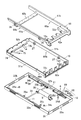
- FIG. 4 is an exploded perspective view of the transfer apparatus in which the belt and the like of the main transport conveyor unit and the rollers and the like of the sub transport conveyor unit are omitted from the exploded perspective view of FIG. 3 and only the frame of each conveyor unit is illustrated. It is a perspective view of the raising / lowering mechanism and geared motor of the transfer apparatus of FIG.
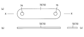
- FIG. 9A is a plan view of the restricting means in FIG. 9, FIG. 9B is a front view, and FIG. 9C is a side view, showing a state in which an external force is applied to the restricting means to bend and warp in the lower chord state.
- (A) is a plan view of the restricting means in FIG. 9,
- (b) is a front view, and
- (c) is a side view, showing a state in which an external force is applied to the restricting means to bend and warp in an upper string state.
- It is explanatory drawing which modeled and demonstrated the relationship between a main conveyance conveyor part or a sub conveyance conveyor part, a main frame, and four control means, (a) is the top view, (b) is the main conveyance conveyor.
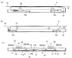
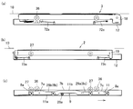
- FIG. 2A is a plan view
- FIG. 2B is a front view
- FIG. 2C is a cross-sectional view taken along line AA of FIG.
- FIG. 2A is a cross-sectional view taken along the line AA in FIG.
- FIG. 2A is a plan view of the transfer device of FIG. 2, in which the sub-transport conveyor unit and the regulating means connected thereto are indicated by solid lines, and the others are indicated by two-dot chain lines
- FIG. 2A is a cross-sectional view taken along the line AA in FIG. It is the perspective view which observed one short side wall part of the belt side frame of the main conveyance conveyor part from the back surface side.
- a control means The modification of a control means is shown, (a) is the perspective view, (b) is a sectional view in the state where the main conveyance conveyor part or the sub conveyance conveyor part is falling, (c) is the main It is sectional drawing of the state which the conveyance conveyor part or the sub conveyance conveyor part is rising, (d) is a cross-sectional view of a control means. It is explanatory drawing which modeled and demonstrated the relationship between a main conveyance conveyor part or a sub conveyance conveyor part, a main frame, and several linear control means, (a) is the top view, (b) is the main figure.
- FIG. 3 is a cross-sectional view conceptually illustrating a cross section AA in FIG. 2, and showing a positional relationship between a transport roller and a belt, and a geared motor.
- the transfer apparatus 1 according to the embodiment of the present invention will be described.
- the transfer device 1 according to the present embodiment has a large number of parts, and not only the shape of each part is complicated but also complicated. Therefore, in order to facilitate understanding of the invention, the outline and characteristic configuration of the transfer apparatus 1 will be described first, and then the specific configuration of each part will be described.
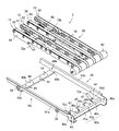
- the transfer device 1 includes a sub-transport conveyor unit (sub-transport unit) 2, a main transport conveyor unit (main transport unit) 3, and an elevating unit. And a geared motor 5. Moreover, in the transfer apparatus 1 of this embodiment, the control means 72 and 73 are provided so that the sub conveyance conveyor part 2 and the main conveyance conveyor part 3 may move straight up and down linearly.
- the sub-transport conveyor unit 2 of the transfer apparatus 1 includes a plurality of transport rollers 14 and a roller-side frame 19 that rotatably supports the transport rollers 14.
- cam followers 27 are respectively provided at four locations below the roller side frame 19.
- the cam follower 27 is a roller.
- the sub-transport conveyor unit 2 is a unit in which a plurality of transport rollers 14 and four cam followers 27 are integrated with the roller-side frame 19.
- At least one of the plurality of transport rollers 14 is a driving roller, and the other is a driven roller, and the driving roller and the driven roller are powered by a belt.
- the driving roller is a motor built-in roller, and a motor and a speed reducer are built in the roller body.
- the sub-transport conveyor section 2 has a transport path formed by a plurality of transport rollers 14, and the article 25 (FIG. 1) that is a transported object placed on the transport path is transported by the rotation of the transport roller 14. Is done.
- the drive motor for driving the roller is disposed in the same plane as each rotating body (roller). ing.
- the roller side frame 19 is restricted from moving in the horizontal direction by the restricting means 73a to 73d, and can reciprocate only in the vertical direction. Details of the restricting means 73a to 73d will be described later.
- the main transfer conveyor unit 3 includes one belt driving roller 80, a plurality of belt driven pulleys 81, annular belts 82 and 88 suspended from both rollers, and the belt side frame 18. And a belt conveyor body 85.
- the belt conveyor main body 85 includes three narrow first narrow belt conveyors 15 (stenosis conveyors) and one second narrow belt conveyor 30 (stenosis conveyor) as shown in FIGS. In addition, four rows are provided in parallel.
- the belt 82 of the first narrow belt conveyor 15 has an annular shape, and, as shown in FIG. 30, the traveling path of the belt 82 includes a conveyance path side 82a on which the article 25 (FIG. 1) is placed, and a lower side of the conveyance path side 82a. There is a return side 82b that passes through.
- the traveling path of the belt 88 of the annular second narrow belt conveyor 30 includes a conveyance path side 88a on which the article 25 (FIG. 1) is placed and a return side 88b that passes below the conveyance path side 88a.
- the conveyance path side 82a and the return side 82b of the first narrow belt conveyor 15 are parallel over almost the entire length in the conveyance direction of the article 25 by the main conveyance conveyor unit 3.
- the first narrow belt conveyor 15 has a substantially constant width in the height direction.
- a constricted portion 90 (FIG. 17) is provided near the center of the second narrow belt conveyor 30.
- the second narrow belt conveyor 30 has a substantially U-shape that is recessed downward by the constricted portion 90.
- the return side 88b of the belt 88 of the second narrow belt conveyor 30 approaches the conveyance path side 88a over a predetermined length in the conveyance direction of the article 25 by the main conveyance conveyor unit 3. Therefore, the width in the height direction of the second narrow belt conveyor 30 is narrower than the other portions in the constricted portion 90.
- a lower portion near the center of the second narrow belt conveyor 30 is recessed to form a constricted portion 90.
- the constricted portion 90 is in the vicinity of the center of the second narrow belt conveyor 30 and extends in the running direction of the belt 82.
- a space 78 (FIGS. 20 and 22C) is provided between the constricted portion 90 of the second narrow belt conveyor 30 and the bottom wall 31 of the main frame 12. , FIG. 30) is formed.
- the space 78 is a region defined by the constricted portion 90 and the bottom wall portion 31, and is located between the portion other than the constricted portion 90 of the second narrow belt conveyor 30 and the bottom wall portion 31, or the first narrow belt conveyor 15.
- the area in the height direction is wider than the space formed between the bottom wall portion 31 and the bottom wall portion 31.
- the space 78 is formed between the adjacent conveying rollers 14 of the sub-conveying conveyor unit 2 in the transfer apparatus 1, and the space 78 is formed in parallel with the conveying rollers 14. ing.
- each conveyance roller 14 does not pass through the space 78.
- the second narrow belt conveyor 30 and the first narrow belt conveyors 15 are arranged in parallel when viewed in plan.
- Each first narrow belt conveyor 15 is moved up and down by the elevating mechanism 4 at the side of the space 78, and the belt 82 of each first narrow belt conveyor 15 is driven by a belt driving roller 80 (travel path side 82 a, return). Travel along side 82b). Therefore, the belt 82 does not pass through the space 78.
- the belt 88 of the second narrow belt conveyor 30 travels on a traveling track (conveying path side 88a, return side 88b) along the constricted portion 90.
- the belt 88 passes through both ends in the longitudinal direction of the space 78 and above the space 78 so as to draw a U-shape, and travels while avoiding the space 78. Therefore, the belt 88 does not pass through the space 78.
- a geared motor 5 as an elevating means is arranged in this space 78.
- the attachment posture of the geared motor 5 is parallel to the conveyance rollers 14 of the sub-conveyance conveyor unit 2 and is disposed between the conveyance rollers 14.
- the position in the height direction of the geared motor 5 arranged in the space 78 is any one of the conveying bodies (conveying rollers) in a state where any of the conveying units (the main conveying conveyor unit 3 and the sub conveying conveyor unit 2) is lowered. 14, a position where a part or the whole of the geared motor 5 is higher than the height of the lower end of the rotation locus or the traveling locus of the belt 82, 88). Therefore, the height of the lower end of the lowered conveying roller 14, the height of the lower end of the belt 82 of the first narrow belt conveyor 15, and the height of the lower end of the belt 88 of the second narrow belt conveyor 30 are Lower than the highest part.
- the geared motor 5 is accommodated and disposed in the space 78 formed inside the transfer device 1, so that it does not collide with the main transport conveyor unit 3 and the sub transport conveyor unit 2 that move up and down.
- the geared motor 5 and the first narrow belt conveyor 15 of the main transfer conveyor unit 3 do not overlap in plan view. Therefore, the belt 82 of the first narrow belt conveyor 15 is moved up and down on the side of the geared motor 5 by the elevating mechanism 4, and the height position of the geared motor 5 increases the height of the lower end portion of the traveling locus of the belt 82. It is over.
- the height position of the geared motor 5 exceeds the height position of the lower end portion of the travel locus of the belt 88 (second narrow belt conveyor 30) of the main conveyor unit 3.
- the lower end portion of the travel locus of the belt 88 is a portion other than the constricted portion 90 on the return side 88b.
- the belt 88 suspended from the roller 67a, the second and third fixed tension pulleys 60b and 60c, and the roller 67b is along the U-shaped constricted portion 90 of the roller mounting member 59. That is, the belt 88 is disposed so as to avoid the geared motor 5 over the entire length of the geared motor 5 from the front end side (output shaft side) side portion of the geared motor 5 to the rear end side portion from above.
- the planar arrangement position of the geared motor 5 is a planar region overlapping the second narrow belt conveyor 30 (conveying unit) of the main transport conveyor unit 3, but the bottom wall of the second narrow belt conveyor 30 and the main frame 12.
- a space 78 is formed between the portions 31, and the geared motor 5 is disposed in the space 78.
- the space 78 is formed along the constricted portion 90 of the second narrow belt conveyor 30 as described above. Therefore, the height position of the geared motor 5 exceeds the height position of the lower end of the return side 88b of the belt 88 (conveyance body) passing through a portion other than the constricted portion 90 of the lowered second narrow belt conveyor 30. .
- the height position of the geared motor 5 is a position lower than the height of the constricted portion 90 of the lowered second narrow belt conveyor 30, and the height position of the lower end of the return side 88b of the belt 88 (conveyance body) is set. Not over. Therefore, the geared motor 5 and the belt 88 (conveyance body) do not interfere with each other even when the main conveyance conveyor section 3 (second narrow belt conveyor 30) is lowered.
- planar arrangement position of the geared motor 5 is a planar area overlapping the sub-conveying conveyor unit 2 (conveying unit), and the height position of the geared motor 5 is the conveying roller 14 ( The height of the lower edge of the (conveyor) is exceeded.
- FIG. 22C the lower end of the transport roller 14 is depicted by a two-dot chain line.
- the conveying roller 14 and the geared motor 5 are overlapped in the height direction.
- the geared motor 5 and each of the transport rollers 14 (transport body) do not interfere with each other because they have different installation positions when viewed in plan.
- the belt conveyor main body 85 of the main transport conveyor unit 3 an example in which three first narrow belt conveyors 15 and one second narrow belt conveyor 30 are provided in the belt conveyor main body 85 of the main transport conveyor unit 3 is shown.
- the second narrow belt conveyor 30 can be omitted. That is, by omitting the second narrow belt conveyor 30, a space for arranging the geared motor 5 of the lifting mechanism 4 in the transfer device 1 may be secured.
- the example which comprises the main conveyance conveyor part 3 with a belt conveyor was shown, you may comprise instead the roller conveyor which arranged the several roller in which articles
- the geared motor 5 of the lifting / lowering means can be disposed in the space 78 in the transfer device 1 without interfering with other members of the transfer device 1. Therefore, the overall height of the transfer device 1 can be reduced.
- geared motors can be used instead of the geared motor 5.
- a motor that can rotate at a low speed and is provided with a separate reduction gear can be used in place of the geared motor 5.
- the cam follower 36 is installed in each of the four locations on the lower outer side of the belt side frame 18.
- the cam follower 36 is a roller.
- the main transport conveyor unit 3 is a unit in which a belt driving roller 80, a plurality of belt driven pulleys 81, and four cam followers 36 are integrated with the belt side frame 18.
- the belt driving roller 80 is a roller with a built-in motor and includes a motor (not shown) having a speed reduction mechanism inside a rotatable outer cylinder. Therefore, the outer cylinder rotates when the motor is driven.
- the belt-side frame 18 is restricted from moving in the horizontal direction by the restricting means 72a to 72d, and can reciprocate only in the vertical direction. Details of the restricting means 72a to 72d will be described later.
- a conveyance path is formed by the belt 82, and the article 25 placed on the conveyance path is conveyed by running the annular belt 82.
- the transport path of the main transport conveyor unit 3 and the transport path of the sub transport conveyor unit 2 are arranged in the same plane area as shown in FIGS. 1, 2, 23, and 24. That is, the belt 82 of the main transport conveyor unit 3 is disposed between the transport rollers 14 of the sub transport conveyor unit 2, and the two transport paths are in the same plane area.
- the raising / lowering means is comprised by the raising / lowering mechanism 4 and the geared motor 5 which combined several members.
- the elevating mechanism 4 includes a gear train 52, a power transmission shaft 39, a pinion gear 26, a horizontal movement member 11, a cam follower 27 belonging to the sub-conveying conveyor unit 2, and a cam follower belonging to the main conveying conveyor unit 3. 36 or the like.
- the power transmission shaft 39 is disposed in a direction intersecting the output shaft of the geared motor 5.
- the power transmission shaft 39 is in a twisted position with respect to the output shaft of the geared motor 5. That is, the height of the power transmission shaft 39 is lower than the output shaft (not shown) of the geared motor 5. Both ends of the power transmission shaft 39 reach the vicinity of both ends of the transfer device 1, and pinion gears 26 are attached to both ends.
- the torsional position means a positional relationship between two straight lines that are not parallel and do not intersect.
- the power transmission shaft 39 is disposed in the transfer apparatus 1 so as to be slightly separated below the respective transport rollers 14 of the main transport conveyor unit 3 and the belts 82 and 88 of the sub transport conveyor unit 2. It is orthogonal to the conveying roller 14 and the belts 82 and 88.
- the gear train 52 connects the output shaft of the geared motor 5 in a twisted position as shown in FIG. 5 and an intermediate portion of the power transmission shaft 39, and the rotational force of the geared motor 5 is applied to the power transmission shaft 39. It is a transmission. Therefore, when the geared motor 5 rotates, the pinion gears 26 attached to both ends of the power transmission shaft 39 rotate.
- two horizontal moving members 11 are arranged in parallel between the roller side frame 19 and the belt side frame 18.
- the horizontal moving member 11 is provided with a rack portion 9 facing downward.
- the horizontal movement member 11 can reciprocate only in the longitudinal direction.
- the pinion gear 26 described above engages with the rack portion 9 formed downward.
- the power transmission shaft 39 is twisted with respect to the output shaft of the geared motor 5 and is disposed below the output shaft (not shown) of the geared motor 5.
- the pinion gear 26 provided on the power transmission shaft 39 is engaged with the rack portion 9 formed downward.
- the horizontal movement member 11 is a linear motion cam and includes a long upper surface 11 b.
- the rack portion 9 described above is provided in the center of the upper surface 11b and on the lower surface side.
- the rack part 9 is engaged with the pinion gear 26 described above.
- the horizontal movement member 11 reciprocates in the horizontal direction. That is, by rotating the geared motor 5 described above, power is transmitted to the horizontal moving member 11 and the horizontal moving member 11 reciprocates.
- the horizontal moving member 11 is a linear cam as described above, and cam recesses 28 and 29 are provided on the upper surface 11b. That is, the cam recesses 28 and 29 are provided on both sides of the rack portion 9, respectively.
- the cam recesses 28 and 29 are fitted with the cam follower 27 provided on the roller side frame 19 and the cam follower 36 provided on the belt side frame 18. That is, when the geared motor 5 rotates and the pinion gear 26 rotates, the upper surface 11b of the horizontal moving member 11 moves horizontally while rotating the cam follower 27, and when the cam recesses 28 and 29 reach the position of the cam follower 27, FIG.
- the cam follower 27 is dropped into the cam recesses 28 and 29 as shown in FIG.
- the roller side frame 19 integrated with the cam follower 27 is lowered, and the sub-transport conveyor unit 2 is lowered downward.
- the main transfer conveyor unit 3 remains in the raised position.
- the main transport conveyor unit 3 and the sub transport conveyor unit 2 are both unitized and arranged in the main frame 12.
- the main transfer conveyor unit 3 and the main frame 12 are coupled only by the four restricting means 72a to 72d.
- the sub-transport conveyor unit 2 and the main frame 12 are also coupled by only four restricting means 73a to 73d.
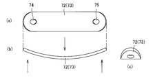
- the restricting means 72 and 73 employed in the transfer device 1 of the present embodiment are leaf springs. That is, the regulating means 72 and 73 are made by punching a thin plate-shaped spring steel, and the planar shape is an oval shape as shown in FIG. That is, the regulating means 72 and 73 are oval thin plates, have elasticity, and bend in a certain direction.
- the restricting means 72 and 73 are easily bent in the direction perpendicular to the plane as shown in FIGS. That is, when a bending force is applied in a direction perpendicular to the plane as shown by arrows in FIGS. However, as shown by the arrows in FIG. 9, it exerts a strong resistance against the force in the twisting direction and is difficult to twist.
- FIG. 13 is an explanatory diagram modeling and explaining the relationship between the main transport conveyor unit 3 or the sub transport conveyor unit 2, the main frame 12, and the four regulating means 72 and 73.
- a rectangular frame A is a model of the main transport conveyor unit 3 or the sub transport conveyor unit 2.
- Surface B is a model of the main frame 12.
- the frame A (the main transport conveyor unit 3 or the sub transport conveyor unit 2) and the surface B are joined by four regulation means 72 and 73. That is, one end side of the regulating means 72 and 73 is joined to the frame A (the main transport conveyor unit 3 or the sub transport conveyor unit 2), and the other end side of the regulating means 72 and 73 is joined to the surface B (the main frame 12).
- the restricting means 72 and 73 are plate bodies and can be fixed simply by screwing them to the frame A and the surface B. Therefore, the assembly of the transfer device 1 is easy.
- the planar positional relationship between the restricting means 72 and 73 is as shown in FIG. 13A, and the frame A-side joining portion 200 of the restricting means 72 and 73 is joined to the frame A, and the restricting means 72 and 73.
- the surface B-side joint portion 201 is in a plane area surrounded by the frame A.
- the regulating means 72 and 73 are arranged in a plane posture, and the plane of the regulating means 72 and 73, the virtual plane of the frame A, and the plane formed by the plane B are substantially parallel. That is, the lower surfaces of the regulating means 72 and 73 are opposed to the plane formed by the main frame 12 as the surface B, and the upper surfaces of the regulating means 72 and 73 are opposed to the virtual plane of the frame A. That is, the restricting means 72 and 73 are elastic plates that are bent in a certain direction, and the restricting means 72 and 73 are moved up and down by the frame A (the main transfer conveyor unit 3 or the auxiliary transfer conveyor unit 2). It is attached between the surface B (main frame 12) and the frame A in a posture matched to the moving direction.
- the restricting means 72 and 73 are leaf springs and are easily bent in a direction perpendicular to the plane, but are not easily twisted.
- the planes of the regulating means 72 and 73 are substantially parallel to the plane formed by the virtual plane of the frame A and the plane B. Therefore, when the individual restricting means 72 and 73 are observed, the frame A side joint portion 200 of the restricting means 72 and 73 can be moved straight in the direction perpendicular to the surface B by bending. That is, when the frame A is lifted by the cam, the restricting means 72 and 73 bend and warp in an upper chord state, and move the frame A vertically without shaking.
- each restricting means 72, 73 are attached between the frame A and the surface B, so that each frame A-side joint 200 of each restricting means 72, 73. Move straight in the direction perpendicular to the plane B.
- four regulating means 72 and 73 are attached between the frame A and the surface B, respectively, and the frame A side joint portion 200 of the regulating means 72 and 73 is a part close to the corner of the frame A.
- the restricting means 72 and 73 have a property of being difficult to twist, a large force is not required for the frame A and the surface B to approach and separate in parallel. When the frame A and the surface B are inclined or twisted, the reaction force of the restricting means 72 and 73 tries to correct them to a parallel posture.
- the restriction means 72 and 73 restrict the frame A so as to move up and down straight with respect to the surface B.
- the main transport conveyor unit 3 and the main frame 12 are coupled by only four regulating means 72, and the main transport conveyor unit 3 is connected to the main by the action of the four regulating means 72. It is restricted to move in a direction perpendicular to the frame 12. More specifically, the belt-side frame 18 of the main conveyor unit 3 is restricted from moving in the horizontal direction by the restricting means 72 and can reciprocate only in the vertical direction.
- the sub-conveying conveyor unit 2 is operated by the four restricting means 73. Therefore, the main frame 12 is restricted so as to move in a vertical direction. That is, the roller-side frame 19 of the sub-conveying conveyor unit 2 is restricted from moving in the horizontal direction by the restricting means 73 and can reciprocate only in the vertical direction.
- the main transport conveyor unit 3 and the sub transport conveyor unit 2 each have four cam followers 36 and 27, and the four cam followers 36 and 27 are moved by the horizontal moving member 11 that is a linear motion cam. Are raised and lowered at the same time. For this reason, the four cam followers 36 of the main transport conveyor unit 3 are lifted and lowered simultaneously by the horizontal moving member 11, so that the main transport conveyor unit 3 moves up and down while maintaining a horizontal posture. The same applies to the sub-conveying conveyor unit 2, and the four cam followers 27 of the sub-conveying conveyor unit 2 are simultaneously moved up and down by the horizontal moving member 11, so that the sub-conveying conveyor unit 2 moves up and down while maintaining a horizontal posture.
- the regulating means 72 and 73 are leaf springs that are extremely thin and are arranged in parallel to the virtual plane of the main transport conveyor unit 3 and the virtual plane of the sub transport conveyor unit 2.
- the restricting means 72 and 73 have a planar posture and the total height is extremely low. That is, the height of the restricting means 72 and 73 is merely the thickness of the leaf spring, and is significantly lower than that of the prior art guide. Therefore, the total height of the transfer apparatus 1 of this embodiment is low.
- the main transport conveyor unit 3 or the sub transport conveyor unit 2 is modeled and the frame A is illustrated, and the main frame 12 is modeled and the surface B is illustrated. It was.
- the belt side frame 18 which is a part of the main transport conveyor unit 3 is smaller than the roller side frame 19 which is a part of the sub transport conveyor unit 2 as shown in FIG.
- the frame 18 is housed in the roller side frame 19. Therefore, both are in a common area in the height direction.
- four regulating means 72a to 72d shown in FIG. 15 are attached between the belt side frame 18 and the main frame 12, and guide the belt side frame 18 in the vertical direction.
- four regulating means 73a to 73d shown in FIG. 21 are attached between the roller side frame 19 and the main frame 12 to guide the roller side frame 19 in the vertical direction.
- the transfer apparatus 1 of this embodiment is arrange
- the transfer device 1 is arranged between the upstream main conveyance line 22 and the downstream main conveyance line 23 arranged in a straight line to form the main line 100, and is orthogonal to the main conveyance lines 22 and 23.
- the auxiliary transport line 24 is connected to the transfer device 1.
- the conveyor line 21 conveys the article 25 along the main line 100 (main conveyance lines 22 and 23) or changes the conveyance direction on the transfer device 1, and transfers the article 25 to the sub line 101 (sub conveyance line 24). ).
- the transfer apparatus 1 includes a main frame 12 that accommodates and arranges all the constituent members, and a main transport conveyor unit 3 that transports an article 25 (FIG. 1) to the main transport line 23 (FIG. 1). And the sub-transport conveyor unit 2 that transports the article 25 to the sub-line 101.
- the transfer device 1 has an elevating mechanism 4.
- the main frame 12 has a bottom wall portion 31, long side wall portions 32a and 32b, and short side wall portions 33a and 33b.
- the bottom wall portion 31 has a rectangular thin plate shape.
- Long side wall portions 32 a and 32 b are provided on the long side edge of the bottom wall portion 31.
- Short side wall portions 33 a and 33 b are provided on the short side edge of the bottom wall portion 31.
- the long side wall portions 32a and 32b and the short side wall portions 33a and 33b are connected to each other to form a frame that surrounds the four sides.
- the long side wall portions 32 a and 32 b and the short side wall portions 33 a and 33 b are fixed orthogonally to the bottom wall portion 31.
- the bottom wall portion 31 is provided with four guide members 68 along the long side wall portions 32a and 32b from the end side to the center side of the long side wall portions 32a and 32b.
- the guide member 68 includes a floor plate 68a, a guide rail 68b, and a screw 68c.
- the floor plate 68a is a substantially rectangular thin plate member.
- the guide rail 68b is a plate-like member having the same length as the floor board 68a and a width smaller than the floor board 68a.
- a guide rail 68b is disposed at the center of the floor plate 68a, and both ends of the both are penetrated by screws 68c and fixed to the bottom wall portion 31.
- the rail part 69 is comprised on the flooring board 68a of the both sides of the guide rail 68b.
- the bottom wall portion 31 is provided with four cylindrical fixing portions 34a to 34d and four cylindrical fixing portions 35a to 35d. A female screw is formed inside each cylindrical fixing portion. Of these eight cylindrical fixing portions, only the cylindrical fixing portions 35c and 35d are longer than the other cylindrical fixing portions.
- One ends of restricting means 73a to 73d are fixed to the four cylindrical fixing portions 34a to 34d of the main frame 12. The other ends of the restricting means 73a to 73d are coupled to the roller-side frame 19 of the sub-transport conveyor unit 2. Further, one end of the restricting means 72a to 72d is fixed to the four cylindrical fixing portions 35a to 35d of the main frame 12. The other ends of the regulating means 72a to 72d are coupled to the belt side frame 18 of the main transport conveyor unit 3. That is, each of the cylindrical fixing portions 34a to 34d and 35a to 35d is connected to a belt side frame 18 and a roller side frame 19 which will be described later via regulating means 72a to 72d and 73a to 73d as shown in FIG.
- An elevating mechanism 4 is provided on the bottom wall portion 31. As shown in FIG. 5, the lifting mechanism 4 includes a geared motor 5, a power transmission shaft 39, a horizontal movement member 11, and the like.
- a helical gear (not shown) is mounted on the output shaft (not shown) of the geared motor 5.
- the geared motor 5 is fixed to the central portion of the bottom wall portion 31 by fixing members 37 a and 37 b with an output shaft (not shown) facing the longitudinal direction of the main frame 12.
- a gear box 38 is fixed to the fixing member 37b.
- An output shaft (not shown) of the geared motor 5 is accommodated in the gear box 38.
- the power transmission shaft 39 has a length slightly shorter than the length of the bottom wall portion 31 in the short direction.
- a helical gear (not shown) different from the helical gear (not shown) provided in the geared motor 5 is provided in the middle of the power transmission shaft 39.
- pinion gears 26 a and 26 b are provided at both ends of the power transmission shaft 39.
- the power transmission shaft 39 extends in the short direction of the main frame 12 and is arranged at the center of the bottom wall portion 31. Near both ends of the power transmission shaft 39 are supported by bearing members 40a and 40b.
- the pinion gear 26a is disposed between the two guide members 68 along the long side wall portion 32a.
- the pinion gear 26b is disposed between the two guide members 68 along the long side wall portion 32b.
- the power transmission shaft 39 passes through the gear box 38 from a direction orthogonal to the output shaft (not shown) of the geared motor 5.
- a helical gear (not shown) of the power transmission shaft 39 is accommodated in the gear box 38.
- a helical gear (not shown) on the geared motor 5 side and a helical gear (not shown) on the power transmission shaft 39 side are directly or indirectly engaged so that power transmission is possible.
- the power transmission shaft 39 is below the output shaft (not shown) of the geared motor 5.
- the power transmission shaft 39 and the output shaft (not shown) of the geared motor 5 are in a torsional positional relationship.
- the horizontal moving member 11 is a long and substantially rectangular parallelepiped member as shown in FIGS. 3, 5, and 6.
- the horizontal movement member 11 has a substantially rectangular cross section, and the horizontal movement member 11 is disposed in the main frame 12 in such a posture that the longitudinal direction of the rectangle of the cross section coincides with the vertical direction.
- a recess is formed in the central portion of the lower surface 11 a of the horizontal moving member 11.
- a rack portion 9 is provided in this recess.
- Rack teeth 9a are formed on the rack portion 9 by appropriate means such as gear cutting. That is, the rack teeth 9a of the rack portion 9 are formed downward.
- the four shafts 10 are provided on the side surface of the horizontal moving member 11 so as to pass through four places in the longitudinal direction of the horizontal moving member 11.
- Two shafts 10 are arranged on both sides of the rack portion 9.
- a pair of induction rollers 6 is attached to each shaft 10.
- the upper surface 11b of the horizontal moving member 11 has a plurality of portions having different heights as shown in FIG. 6, FIG. 7, and FIG. That is, on the upper surface 11b of the horizontal moving member 11, in order from one end, the first low position portion 8a (cam recessed portion 28a), the first high position portion 7a, the second low position portion 8b (cam recessed portion 28b), the first A second high position portion 7b, a third low position portion 8c (cam concave portion 29a), a third high position portion 7c, and a fourth low position portion 8d (cam concave portion 29b) are formed.
- the first low position portion 8 a and the fourth low position portion 8 d are formed at both ends of the horizontal movement member 11.
- the second high position portion 7b is formed at the central portion in the longitudinal direction of the horizontal moving member 11, and constitutes the highest portion of the upper surface 11b. That is, the second high position portion 7b is formed on the upper surface 11b of the central portion in the longitudinal direction of the horizontal moving member 11, and the rack portion 9 is formed on the lower surface 11a below the second high position portion 7b. .
- the guide roller 6 is disposed on the rail portion 69 of the floor plate 68 a of the guide member 68. That is, the pair of guide rollers 6 are arranged on both sides of the guide rail 68b and can reciprocate along the guide rail 68b.
- FIG. 6C shows a state in which the pinion gear 26 a (26 b) is engaged with the central portion of the rack portion 9 of the horizontal moving member 11.
- the pinion gear 26a rotates counterclockwise as viewed in FIG. 6C
- the horizontal movement member 11 moves to the left as shown in FIG. 8C.
- the pinion gear 26a rotates clockwise as viewed in FIG. 6C
- the horizontal movement member 11 moves to the right as shown in FIG. 7C.
- the main conveyor unit 3 includes a belt-side frame 18 and a belt conveyor body 85.
- the belt conveyor main body 85 is formed by four rows of three narrow first narrow belt conveyors 15 (stenosis conveyor) and one second narrow belt conveyor 30 (stenosis conveyor) in parallel.
- the driving pulley of the four rows of narrow belt conveyors is shared by one belt driving roller 80. That is, in this embodiment, one belt drive roller 80 (motor built-in roller) is used as a common drive pulley.
- the first narrow belt conveyor 15 has a structure as shown in FIG. 16, and a plate-like roller mounting member 16 is provided on one side, and the belt mounting member 16 includes one belt driven pulley 81 and two belt driven pulleys 81. A fixed tension pulley 83 and a plurality of rollers 17 are provided.
- a narrow belt 82 is suspended between a common driving pulley (belt driving roller 80) and each driven pulley.
- Each roller 17 is disposed inside the annular belt 82 so as to support the load applied to the belt 82. That is, the belt driving roller 80 is arranged in the horizontal direction in the same row as the belt driven pulley 81 fixed to the roller mounting member 16 and the plurality of rollers 17. Therefore, the overall height of the main transport conveyor unit 3 is low.
- the fixed tension pulley 83 presses the belt 82 from the outside.
- the roller mounting member 16 has a structure in which an elongated plate-like member is bent in an L shape along the longitudinal direction.
- an auto tensioner 87 is attached to the belt 82. As shown in FIG. 16, the auto tensioner 87 is attached to the roller mounting member 16.
- the auto tensioner 87 includes a swing piece 94, a movable tension pulley 84, and a spring 86.
- the roller mounting member 16 is provided with a long hole-shaped spring accommodating hole and a spring fixing hole.
- the spring fixing hole is provided at one end in the longitudinal direction of the spring accommodation hole.
- One end of a spring 86 is fixed to the spring fixing hole of the roller mounting member 16. A part of the spring 86 is accommodated in the spring accommodating hole.
- the rocking piece 94 is fixed to the roller mounting member 16 via a shaft so as to be rotatable.
- a movable tension pulley 84 is provided at the tip of the swing piece 94.
- the movable tension pulley 84 can freely rotate with respect to the swing piece 94.
- the other end of the spring 86 is fixed to the rear end portion of the swing piece 94.
- the spring 86 connects the spring fixing hole 92b of the roller mounting member 16 and the rear end portion of the swing piece 94, and a part of the spring 86 is disposed in the spring accommodating hole 92a.
- the spring 86 is a tension spring and pulls the swing piece 94.
- the swing piece 94 rotates (swings), the movable tension pulley 84 fixed to the tip of the swing piece 94 presses the belt 82, and an appropriate tension is applied to the belt 82.
- the auto tensioner 87 has a movable tension pulley 84, and the movable tension pulley 84 can freely rotate, and can move toward and away from the belt 82.
- short side wall portion 42b and the roller mounting member 16 are bolted.
- short side wall portion 42a and the roller attachment member 16 are bolted.
- the second narrow belt conveyor 30 has a structure as shown in FIGS. 17 to 19, and a plate-like roller mounting member 59 is provided on one side, and one belt driven pulley 81 and one roller mounting member 59 are provided on the roller mounting member 59.
- Three fixed tension pulleys 60 first fixed tension pulley 60a, second fixed tension pulley 60b, and third fixed tension pulley 60c), a plurality of rollers 67 (67a to 67c), and a plurality of small diameter rollers 89 are provided. ing.
- a belt driven pulley 81, three fixed tension pulleys 60, a plurality of rollers 67, and a plurality of small diameter rollers 89 are rotatably mounted on the roller mounting member 59.
- three fixed tension pulleys 60 (60a to 60c), a plurality of rollers 67 (67a to 67c), and a plurality of small diameter rollers 89 are provided.
- a narrow and narrow belt 88 is suspended.
- the rollers 67a to 67c and the plurality of small-diameter rollers 89 are disposed inside the belt 88 so as to support the load applied to the belt 88.
- Each of the fixed tension pulleys 60a to 60c applies tension to the belt 88 by pressing the belt 88 from the outside.
- the roller attachment member 59 is provided with a constricted portion 90 having a small size in the height direction.
- the constricted portion 90 is provided near the lower center of the second narrow belt conveyor 30.
- the second narrow belt conveyor 30 has a U-shape.
- a plurality of small diameter rollers 89 are arranged along the constricted portion 90.
- the annular belt 88 passes through an upper conveyance path side 88a and a lower return side 88b, which are travel loci.
- the article 25 (FIG. 1) is placed on the belt 88 passing through the conveyance path side 88a, and a load is applied.
- Each roller 67 (67a to 67c) and each small-diameter roller 89 support the load of the article 25.
- each member of the second narrow belt conveyor 30 is as follows. That is, the belt driving roller 80 and the belt driven pulley 81 are arranged on both sides, and in the belt 88, a roller 67a, a plurality of small-diameter rollers 89, and rollers 67b and 67c are arranged in this order from the belt driving roller 80 side. Yes. A first fixed tension pulley 60a that presses the belt 88 from the outside is disposed between the belt driving roller 80 and the roller 67a.
- a second fixed tension pulley 60b is disposed between the roller 67a and the small diameter roller 89
- a third fixed tension pulley 60c is disposed between the small diameter roller 89 and the roller 67b. That is, the second and third fixed tension pulleys 60 b and 60 c are arranged on both sides of the plurality of small diameter rollers 89.
- the belt 88 is lifted along the constricted portion 90 of the roller mounting member 59, and the belt 88 A part of the return side 88b (lower side) of the traveling locus of this is approaching the conveyance path side 88a (upper side).
- a portion of the belt 88 where the conveyance path side 88a and the return side 88b are close to each other is protected by the upper cover 50a and the lower cover 50b.
- a space 78 is formed below the upper cover 50a and the lower cover 50b.
- an auto tensioner 87 is attached to the second narrow belt conveyor 30.
- the auto tensioner 87 has the same structure as the auto tensioner 87 of the first narrow belt conveyor 15, and a duplicate description is omitted.
- the second narrow belt conveyor 30 is bolted to the belt side frame 18 in the same manner as the first narrow belt conveyor 15.
- the belt side frame 18 is a frame-like member composed of two long side wall portions 41a and 41b and two short side wall portions 42a and 42b as shown in FIGS.
- the long side wall portions 41a and 41b have the same structure, but the left and right sides are different.
- the long side wall 41a will be mainly described, and redundant description on the long side wall 41b will be omitted.
- the long side wall portion 41a is a long flat plate-like member, and the upper side is bent at a right angle to form a flange shape.
- a projecting portion 48a projecting downward is provided at one end of the long side wall portion 41a.
- a protrusion 48b protruding downward is provided in the vicinity of the end opposite to the end where the protrusion 48a of the long side wall 41a is provided.
- the protrusions 48a and 48b protrude to the same extent.
- a roller fixing hole 43 is provided in the vicinity of the end of the long side wall portion 41a on the protruding portion 48a side.
- follower fixing holes 44a are provided at two locations on the long side wall 41a.
- the follower fixing hole 44a is a hole for rotatably supporting the cam follower 36.
- Two cam followers 36 are arranged at a predetermined interval in the longitudinal direction of the long side wall 41a, and both the cam followers 36 are provided outside the long side wall 41a.
- One cam follower 36 is provided at a portion from which the protruding portion 48b protrudes.
- the short side wall portions 42a and 42b are flat plate-like members shorter than the long side wall portions 41a as shown in FIGS.
- Each part of the short side wall part 42a is appropriately bent as shown in FIGS. 15 and 25, and has a lower horizontal part 45a, a vertical part 45b, and an upper horizontal part 45c.
- the lower horizontal portion 45a and the upper horizontal portion 45c are arranged on opposite sides of the vertical portion 45b.
- the upper horizontal portion 45c is provided with four projecting portions 46a to 46d. Each of the protruding portions 46a to 46d protrudes to the opposite side of the vertical portion 45b in the same plane as the upper horizontal portion 45c.
- the protrusions 46a to 46d are arranged at predetermined equal intervals in order from the end of the upper horizontal portion 45c.
- a hole 47 is provided in the vicinity of the free end of each of the protrusions 46a to 46d.
- cylindrical fixing portions 70c and 70d are provided on the lower surface side of the protruding portions 46a and 46d.
- the cylindrical fixing portions 70 c and 70 d are fixed to the protruding portions 46 a and 46 d by screws that pass through the holes 47.
- Female screws are formed inside the cylindrical fixing portions 70c and 70d.
- One ends of restricting means 72c and 72d are fixed to the cylindrical fixing portions 70c and 70d.
- Both ends of the short side wall portion 42a are connected to the tips of the protruding portions 48a of the long side wall portions 41a and 41b, respectively.
- the projecting portions 46a to 46d of the short side wall portion 42a are arranged so as to face the center side of the long side wall portions 41a and 41b, and the lower horizontal portion 45a is formed of the long side wall portions 41a and 41b. It is arrange
- the short side wall portion 42b is an elongated plate member having the same length as the short side wall portion 42a.
- the first narrow belt conveyor 15 and the second narrow belt conveyor 30 are bolted along the long side of the short side wall portion 42b.
- the long side wall portions 41a and 41b and the short side wall portions 42a and 42b constitute a frame-like belt side frame 18. Both end portions of the short side wall portion 42a (lower horizontal portion 45a) are fixed to the protruding portions 48a of the long side wall portions 41a and 41b, and both end portions of the short side wall portion 42b are on the long side side. It is being fixed to the front-end
- the sub-transport conveyor unit 2 includes a roller side frame 19 and a roller conveyor body 13 as shown in FIG.
- the roller conveyor body 13 is disposed on the roller side frame 19.
- at least one of the plurality of transport rollers 14 is a driving roller, and the other is a driven roller, and the roller conveyor body 13 is driven by a belt.
- the roller side frame 19 has two long side wall portions 51a and 51b and two short side wall portions 52a and 52b.
- the long side wall portions 51a and 51b have the same structure, but the left and right sides are different.
- the long side wall 51a will be mainly described, and redundant description on the long side wall 51b will be omitted.
- the roller side frame 19 is a frame-like member composed of long side wall portions 51a and 51b and short side wall portions 52a and 52b as shown in FIGS.
- the roller side frame 19 is slightly larger than the belt side frame 18 and can accommodate the belt side frame 18 therein.
- the long side wall 51a is composed of a long flat plate member.
- the upper side of the long side wall 51a is bent at a right angle to form a flange shape.
- follower fixing holes 54a are provided at two locations on the long side wall 51a.
- the follower fixing hole 54a is a hole for rotatably supporting the cam follower 27 (depicted on the long side wall 51b).
- the two cam followers 27 are arranged at a predetermined interval in the longitudinal direction of the long side wall portion 51a, and both the cam followers 27 are provided at a portion off the center of the long side wall portion 51a.
- the short side wall portions 52a and 52b are flat members that are shorter than the long side wall portions 51a.
- the short side wall portion 52a has a structure in which a flat plate is bent into a substantially U shape. That is, as shown in FIG. 26, the short side wall portion 52a has a bottom wall portion 55a and vertical wall portions 55b and 55c, and the vertical wall portions 55b and 55c stand up from both sides of the bottom wall portion 55a. .
- the vertical wall 55c has a higher standing height from the bottom wall 55a than the vertical wall 55b.
- fixing holes 76a and 76b are provided in the vicinity of both ends in the longitudinal direction of the bottom wall portion 55a.
- Projecting portions 56a to 56e projecting upward are provided on the upper edge portion of the vertical wall portion 55c.
- the protrusions 56a to 56e are arranged at a predetermined interval of equal intervals.
- the second projecting portion 56b from the end has a longer projecting length than the other projecting portions, and is bent at a right angle in a direction away from the bottom wall portion 55a to form a horizontal portion 53. It is bent to face.
- the protrusions 56a to 56e have the same height. Holes 57 are provided in the vicinity of the tips of the protrusions 56a to 56e.
- Vertical wall portions 58 are provided at both ends in the longitudinal direction of the short side wall portion 52a.
- the vertical wall portion 58 is lower than the projecting portions 56a to 56e.
- the short side wall portion 52b is composed of a plate-like member having a length comparable to that of the short side wall portion 52a.
- the short side wall portion 52b is bent along the longitudinal direction to form a bottom wall portion 61a and a vertical wall portion 61b.
- the bottom wall portion 61a is provided with two fixing holes 62a and 62b at a predetermined interval.
- Notches 65a to 65e are provided at equal intervals on the upper side of the vertical wall 61b. Projections 63a to 63d projecting upward are formed on the upper side of the vertical wall 61b by the notches 65a to 65e.
- connection wall part 64 which continues the vertical wall part 61b is provided in the both ends of the short side wall part 52b.
- the connection wall part 64 has orthogonal side wall parts 64a and 64b.
- the side wall part 64a is connected orthogonally to the vertical wall part 61b.
- the width of the bottom wall portion 61a and the width of the side wall portion 64a are the same, and the side wall portion 64a is bent in the same direction as the bottom wall portion 61a with respect to the vertical wall portion 61b.
- the side wall portion 64b is orthogonal to the side wall portion 64a and extends to the side where the bottom wall portion 61a is not present.
- the roller-side frame 19 is a frame-like member in which the long side wall portions 51a and 51b are opposed to each other, one end is connected by the short side wall portion 52a, and the other end is connected by the short side wall portion 52b. It is. Lower portions of one ends of the long side wall portions 51a and 51b are connected to the vertical wall portions 58 on both sides of the short side wall portion 52a.
- the other ends of the long side wall portions 51a and 51b are connected to the side wall portions 64b of the connection wall portions 64 on both sides of the short side wall portion 52b. Therefore, a space 66b is formed below the connection wall portion 64 and the long side wall portions 51a and 51b.
- the cam follower 27 is rotatably fixed to the long side wall portions 51a and 51b while floating in the air above the space 66b. Further, the cam follower 27 is disposed inside the frame of the roller side frame 19.
- the main frame 12 and the belt side frame 18 are connected by four restricting means 72a to 72d (plate springs).
- the restricting means 72a to 72d are thin and thin plate-like members as described above, and are members having both rigidity and elasticity. As shown in FIG. 9, holes 74 and 75 are provided near both ends of the restricting means 72a to 72d.
- the restricting means 73a to 73d are members having the same configuration as the restricting means 72a to 72d. Holes 74 and 75 are provided near both ends of the regulating means 73a to 73d.
- the short side wall portion 52a of the roller side frame 19 is connected to the main frame 12 by restricting means 73c and 73d. Specifically, the fixing hole 76a of the short side wall portion 52a and the hole 74 of the restricting means 73c are coincident with each other and are fixed with bolts and nuts. Further, as shown in FIG.
- the cylindrical fixing portion 34c of the main frame 12 and the hole 75 of the restricting means 73c coincide with each other and are fixed with bolts and nuts.
- the restricting means 73 c is fixed to the fixing hole 76 a of the short side wall portion 52 a and the cylindrical fixing portion 34 c of the main frame 12.
- the restricting means 73d is fixed to the fixing hole 76b of the short side wall portion 52a and the cylindrical fixing portion 34d of the main frame 12.
- the short side wall portion 52b of the roller side frame 19 is connected to the main frame 12 by regulating means 73a and 73b shown in FIG. That is, the restricting means 73a and 73b are fixed to the fixing holes 62a and 62b of the short side wall portion 52b and the cylindrical fixing portions 34a and 34b (FIG. 4) of the main frame 12, respectively.
- the transfer device 1 in a state where the above-described members are assembled has a planar shape as shown in FIG. 22A and a front shape as shown in FIG.
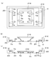
- the positional relationship between the restricting means 72 and 73 is as shown in FIGS. That is, since the eight restricting means 72 and 73 are arranged at positions separated from each other as shown in FIGS. 23 (a) and 24 (a), the other restricting means 72, 73 when bent. 73, the main conveyance conveyor part 3 and the sub conveyance conveyor part 2 can be raised / lowered smoothly.
- the eight regulating means 72 and 73 are in the same region in the height direction as shown in FIGS. 23B and 24B, and are transferred because the individual heights are low. The overall height of the device 1 is low.
- the transfer device 1 When the conveyance direction of the article 25 shown in FIG. 1 is set, the transfer device 1 is operated as follows. When the article 25 is transported from the upstream main transport line 22 to the downstream main transport line 23, the main transport conveyor unit 3 of the transfer device 1 is raised, and the belts 82 and 88 are disposed on the transport path. The sub-conveying conveyor unit 2 is lowered and the conveying roller 14 is retracted below the conveying path. That is, the geared motor 5 is driven to move the horizontal moving member 11 to the right as shown in FIG. 7C, and the cam follower 36 of the main transfer conveyor unit 3 is moved to the first high position portion 7a and the third high position.
- the cam followers 27 of the sub-transport conveyor unit 2 are arranged on the first low position portion 8a (cam concave portion 28a) and the third low position portion 8c (cam concave portion 29a).
- the main transport conveyor unit 3 moves to the raised position
- the sub-transport conveyor unit 2 moves to the lowered position.
- Belts 82 and 88 are arranged on the conveying surface, and the article 25 is conveyed to the downstream main conveying line 23 side by the main conveying conveyor unit 3 of the transfer device 1.
- the regulating means 72 and 73 guide the main transport conveyor unit 3 and the sub transport conveyor unit 2 to move in the vertical direction.
- the sub transport conveyor unit 2 of the transfer device 1 is raised, and the transport rollers 14 are arranged on the transport path.
- the conveying conveyor unit 3 is lowered and the belts 82 and 88 are retracted downward in the conveying path. That is, the geared motor 5 is driven to move the horizontal moving member 11 to the left as shown in FIG. 8C, and the cam follower 36 of the main transfer conveyor unit 3 is moved to the second low position portion 8b (cam recessed portion 28a).
- the cam follower 27 of the sub-transport conveyor unit 2 is disposed on the first high position portion 7a and the third high position portion 7c, as well as on the fourth low position portion 8d (cam recess 29b).
- the main transfer conveyor unit 3 moves to the lowered position, and the auxiliary transfer conveyor unit 2 moves to the raised position.
- a conveyance roller 14 is disposed on the conveyance surface, and the article 25 is conveyed to the sub conveyance line 24 side by the sub conveyance conveyor unit 2 of the transfer device 1.
- the restricting means 72 and 73 guide the main transport conveyor unit 3 and the sub transport conveyor unit 2 to move in the vertical direction.
- leaf springs are employed as the restricting means 72 and 73.
- the sub-transport conveyor unit 2 and the main transport conveyor unit 3 are guided so as to move up and down in a straight line by utilizing the elasticity of the leaf springs.
- the present invention is not limited to this configuration, and a plate body that can be inclined can be employed instead of the plate spring.
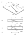
- FIG. 27 shows an example in which a tiltable plate body 111 is employed as the regulating means 110.
- the main body of the restricting means 110 is a plate body 111 that has a small elastic force and is not easily bent.
- both ends of the regulating means 110 are connected to the frame A (the main transport conveyor unit 3 or the sub transport conveyor unit 2) and the surface B (the main frame 12) via hinges 112 and 113, as shown in FIG. It can take a posture close to horizontal as shown in b) and a tilted posture as shown in FIG.
- the hinges 112 and 113 have a certain amount of backlash, and the change in the distance in the longitudinal direction between the hinges 112 and 113 due to the plate body 111 changing to the inclined posture is absorbed by the backlash.
- the restricting means 110 is a plate and is inclined in a direction perpendicular to the plane, but is hardly twisted. Further, the plane of each regulating means 110 is substantially parallel to the plane formed by the virtual plane of the frame A and the plane B. Therefore, when the individual regulating means 110 is observed, the frame A can be moved straight in the direction perpendicular to the surface B by being inclined. That is, when the frame A is lifted by the cam, each regulating means 110 is inclined, and the frame A can be moved vertically without shaking.
- the restricting means 110 employed in the present embodiment is a plate, but need not be bent. Therefore, for example, the cross section may have a “U” shape as shown in FIG. That is, the regulating means 110 does not necessarily have to be planar.
- the restricting means 120 shown in FIG. 28 also employs a tiltable plate 121, but shows an example in which the hinge is omitted. That is, the main body portion of the restricting means 120 is a plate body 121, which has a small elastic force and is not easily bent. On the other hand, there are holes 126, 127 at both ends of the restricting means 120, and fastening elements 123, 125 such as pins or screws are inserted into the holes 126, 127 so that the frame A (the main transport conveyor unit 3 or the sub transport conveyor) is inserted. Part 2) and face B (main frame 12).
- the holes 126 and 127 at both ends of the restricting means 120 are larger than the fastening elements 123 and 125 such as pins or screws, and the fastening elements 123 and 125 loosely restrain both ends of the restricting means 120. Only. For this reason, it is possible to take a posture close to horizontal as shown in FIG. 28B and an inclined posture as shown in FIG.
- the restricting means 120 employed in the present embodiment is a plate, but does not need to be bent. Therefore, for example, the cross section may have a “U” shape as shown in FIG. That is, the regulating means 120 does not necessarily have to be planar.
- FIG. 29 employs a wire rod such as a piano wire as the regulating means 130.
- the restricting means 130 employed in the present embodiment is a wire material such as a piano wire and has elasticity in the bending direction.
- the frame A (the main transport conveyor unit 3 or the sub transport conveyor unit 2) and the surface B are joined by a large number of regulating means 130.
- the frame A can be moved straight in the direction perpendicular to the surface B. That is, when the frame A is lifted by the cam, each regulating means 130 is inclined, and the frame A can be moved vertically without shaking.
Landscapes
- Engineering & Computer Science (AREA)
- Mechanical Engineering (AREA)
- Relays Between Conveyors (AREA)
Abstract
La présente invention concerne un dispositif de transfert dont la hauteur totale peut être réduite par rapport à la technique associée. Le dispositif de transfert (1) comprend : une unité de convoyeur principale (3) qui présente un corps de convoyeur principal (82) ; une unité de convoyeur secondaire (2) qui présente un corps de convoyeur secondaire (14) ; et un mécanisme de levage (4) qui lève ou abaisse l'unité de convoyeur principale (3) et l'unité de convoyeur secondaire (2) afin de créer une différence verticale entre elles ; et un moteur (5) permettant d'actionner le mécanisme de levage (4). L'emplacement plan du moteur (5) est une région plane chevauchant le corps de convoyeur principal (82) et le corps de convoyeur secondaire (14), et l'emplacement vertical du moteur (5) est une position telle que, avec l'une quelconque des unités de convoyeur (3, 2) abaissée, tout ou partie du moteur (5) est plus élevé que l'extrémité inférieure de l'emplacement rotatif ou de l'emplacement mobile du corps de convoyeur correspondant (82, 14). Ainsi, la hauteur totale du dispositif de transfert (1) peut être réduite en disposant le moteur (5) à l'intérieur du dispositif de transfert (1).
Priority Applications (4)
| Application Number | Priority Date | Filing Date | Title |
|---|---|---|---|
| EP15744073.6A EP3100966B1 (fr) | 2014-01-28 | 2015-01-26 | Dispositif de transfert |
| US15/113,193 US10053300B2 (en) | 2014-01-28 | 2015-01-26 | Transfer device |
| CN201580017233.5A CN106132849B (zh) | 2014-01-28 | 2015-01-26 | 移载装置 |
| US16/034,911 US10301123B2 (en) | 2014-01-28 | 2018-07-13 | Transfer device |
Applications Claiming Priority (6)
| Application Number | Priority Date | Filing Date | Title |
|---|---|---|---|
| JP2014013835 | 2014-01-28 | ||
| JP2014-013835 | 2014-01-28 | ||
| JP2014-039735 | 2014-02-28 | ||
| JP2014039736A JP2015163549A (ja) | 2014-01-28 | 2014-02-28 | 移載装置 |
| JP2014-039736 | 2014-02-28 | ||
| JP2014039735A JP6304486B2 (ja) | 2014-01-28 | 2014-02-28 | 移載装置 |
Related Child Applications (2)
| Application Number | Title | Priority Date | Filing Date |
|---|---|---|---|
| US15/113,193 A-371-Of-International US10053300B2 (en) | 2014-01-28 | 2015-01-26 | Transfer device |
| US16/034,911 Division US10301123B2 (en) | 2014-01-28 | 2018-07-13 | Transfer device |
Publications (1)
| Publication Number | Publication Date |
|---|---|
| WO2015115357A1 true WO2015115357A1 (fr) | 2015-08-06 |
Family
ID=53756931
Family Applications (1)
| Application Number | Title | Priority Date | Filing Date |
|---|---|---|---|
| PCT/JP2015/051993 Ceased WO2015115357A1 (fr) | 2014-01-28 | 2015-01-26 | Dispositif de transfert |
Country Status (1)
| Country | Link |
|---|---|
| WO (1) | WO2015115357A1 (fr) |
Cited By (1)
| Publication number | Priority date | Publication date | Assignee | Title |
|---|---|---|---|---|
| DE102017107505A1 (de) * | 2017-04-07 | 2018-10-11 | Jungheinrich Aktiengesellschaft | Hubwerk |
Citations (7)
| Publication number | Priority date | Publication date | Assignee | Title |
|---|---|---|---|---|
| JPH0672607A (ja) * | 1992-08-25 | 1994-03-15 | Dainippon Printing Co Ltd | 短冊状板材の反転集積装置 |
| JPH06115679A (ja) * | 1992-10-09 | 1994-04-26 | Murata Mach Ltd | 方向転換装置 |
| JP2000168948A (ja) * | 1998-11-30 | 2000-06-20 | Ito Denki Kk | クロスフィーダ |
| JP2001225946A (ja) | 2000-02-10 | 2001-08-21 | Misuzu Koki Kk | 多列多段コンベア装置への供給システム |
| JP2003112821A (ja) * | 2001-10-10 | 2003-04-18 | Toho Kikai Kogyo Kk | 搬送方向変換装置 |
| JP2012051679A (ja) | 2010-08-31 | 2012-03-15 | Ito Denki Kk | 移載装置 |
| JP2013230914A (ja) * | 2012-04-27 | 2013-11-14 | Ito Denki Kk | 移載装置 |
-
2015
- 2015-01-26 WO PCT/JP2015/051993 patent/WO2015115357A1/fr not_active Ceased
Patent Citations (7)
| Publication number | Priority date | Publication date | Assignee | Title |
|---|---|---|---|---|
| JPH0672607A (ja) * | 1992-08-25 | 1994-03-15 | Dainippon Printing Co Ltd | 短冊状板材の反転集積装置 |
| JPH06115679A (ja) * | 1992-10-09 | 1994-04-26 | Murata Mach Ltd | 方向転換装置 |
| JP2000168948A (ja) * | 1998-11-30 | 2000-06-20 | Ito Denki Kk | クロスフィーダ |
| JP2001225946A (ja) | 2000-02-10 | 2001-08-21 | Misuzu Koki Kk | 多列多段コンベア装置への供給システム |
| JP2003112821A (ja) * | 2001-10-10 | 2003-04-18 | Toho Kikai Kogyo Kk | 搬送方向変換装置 |
| JP2012051679A (ja) | 2010-08-31 | 2012-03-15 | Ito Denki Kk | 移載装置 |
| JP2013230914A (ja) * | 2012-04-27 | 2013-11-14 | Ito Denki Kk | 移載装置 |
Non-Patent Citations (1)
| Title |
|---|
| See also references of EP3100966A4 * |
Cited By (1)
| Publication number | Priority date | Publication date | Assignee | Title |
|---|---|---|---|---|
| DE102017107505A1 (de) * | 2017-04-07 | 2018-10-11 | Jungheinrich Aktiengesellschaft | Hubwerk |
Similar Documents
| Publication | Publication Date | Title |
|---|---|---|
| JP6304486B2 (ja) | 移載装置 | |
| JP6706745B2 (ja) | 移載装置 | |
| JP6647528B2 (ja) | 昇降装置 | |
| JP6140468B2 (ja) | 被搬送物の方向転換装置 | |
| JP6861432B2 (ja) | 搬送装置及びコンベヤユニット | |
| JP6140467B2 (ja) | 被搬送物の方向転換装置 | |
| JP2014152025A (ja) | 被搬送物の方向転換装置 | |
| JP2006315865A (ja) | 方向切換用ローラー付きチェーン型コンベヤ | |
| KR20120128212A (ko) | 트레이 이송시스템 | |
| KR102813778B1 (ko) | 컨베이어 장치용 디버터 | |
| CN101842302A (zh) | 基板输送装置 | |
| KR101448474B1 (ko) | 이송 경로 전환 장치 | |
| WO2015115357A1 (fr) | Dispositif de transfert | |
| CN110217541B (zh) | 可升降移载装置及物料输送系统 | |
| WO2023276993A1 (fr) | Dispositif de transfert | |
| EP4061752A1 (fr) | Transporteur, système de transport et procédé de fabrication de transporteur | |
| EP2090531A1 (fr) | Transporteur à chaîne comportant un roulement à changement de direction | |
| JP7680738B2 (ja) | 移載装置 | |
| JP2013001463A (ja) | 昇降装置 | |
| JP2021127597A (ja) | 扉装置 | |
| JP6685834B2 (ja) | 浮上搬送装置 | |
| KR20210152610A (ko) | 방향전환부 및 이를 포함하는 컨베이어 장치 | |
| JP4552604B2 (ja) | 搬送装置における被搬送物の位置決め装置 |
Legal Events
| Date | Code | Title | Description |
|---|---|---|---|
| 121 | Ep: the epo has been informed by wipo that ep was designated in this application |
Ref document number: 15744073 Country of ref document: EP Kind code of ref document: A1 |
|
| WWE | Wipo information: entry into national phase |
Ref document number: 15113193 Country of ref document: US |
|
| NENP | Non-entry into the national phase |
Ref country code: DE |
|
| REEP | Request for entry into the european phase |
Ref document number: 2015744073 Country of ref document: EP |
|
| WWE | Wipo information: entry into national phase |
Ref document number: 2015744073 Country of ref document: EP |