WO2015115404A1 - 空気調和システム - Google Patents
空気調和システム Download PDFInfo
- Publication number
- WO2015115404A1 WO2015115404A1 PCT/JP2015/052153 JP2015052153W WO2015115404A1 WO 2015115404 A1 WO2015115404 A1 WO 2015115404A1 JP 2015052153 W JP2015052153 W JP 2015052153W WO 2015115404 A1 WO2015115404 A1 WO 2015115404A1
- Authority
- WO
- WIPO (PCT)
- Prior art keywords
- heat pump
- unit
- heating operation
- switching
- heat source
- Prior art date
- Legal status (The legal status is an assumption and is not a legal conclusion. Google has not performed a legal analysis and makes no representation as to the accuracy of the status listed.)
- Ceased
Links
Images


Classifications
-
- F—MECHANICAL ENGINEERING; LIGHTING; HEATING; WEAPONS; BLASTING
- F24—HEATING; RANGES; VENTILATING
- F24D—DOMESTIC- OR SPACE-HEATING SYSTEMS, e.g. CENTRAL HEATING SYSTEMS; DOMESTIC HOT-WATER SUPPLY SYSTEMS; ELEMENTS OR COMPONENTS THEREFOR
- F24D19/00—Details
- F24D19/10—Arrangement or mounting of control or safety devices
- F24D19/1084—Arrangement or mounting of control or safety devices for air heating systems
- F24D19/1087—Arrangement or mounting of control or safety devices for air heating systems system using a heat pump
-
- F—MECHANICAL ENGINEERING; LIGHTING; HEATING; WEAPONS; BLASTING
- F24—HEATING; RANGES; VENTILATING
- F24D—DOMESTIC- OR SPACE-HEATING SYSTEMS, e.g. CENTRAL HEATING SYSTEMS; DOMESTIC HOT-WATER SUPPLY SYSTEMS; ELEMENTS OR COMPONENTS THEREFOR
- F24D12/00—Other central heating systems
- F24D12/02—Other central heating systems having more than one heat source
-
- F—MECHANICAL ENGINEERING; LIGHTING; HEATING; WEAPONS; BLASTING
- F24—HEATING; RANGES; VENTILATING
- F24D—DOMESTIC- OR SPACE-HEATING SYSTEMS, e.g. CENTRAL HEATING SYSTEMS; DOMESTIC HOT-WATER SUPPLY SYSTEMS; ELEMENTS OR COMPONENTS THEREFOR
- F24D15/00—Other domestic- or space-heating systems
- F24D15/02—Other domestic- or space-heating systems consisting of self-contained heating units, e.g. storage heaters
-
- F—MECHANICAL ENGINEERING; LIGHTING; HEATING; WEAPONS; BLASTING
- F24—HEATING; RANGES; VENTILATING
- F24D—DOMESTIC- OR SPACE-HEATING SYSTEMS, e.g. CENTRAL HEATING SYSTEMS; DOMESTIC HOT-WATER SUPPLY SYSTEMS; ELEMENTS OR COMPONENTS THEREFOR
- F24D15/00—Other domestic- or space-heating systems
- F24D15/04—Other domestic- or space-heating systems using heat pumps
-
- F—MECHANICAL ENGINEERING; LIGHTING; HEATING; WEAPONS; BLASTING
- F24—HEATING; RANGES; VENTILATING
- F24F—AIR-CONDITIONING; AIR-HUMIDIFICATION; VENTILATION; USE OF AIR CURRENTS FOR SCREENING
- F24F11/00—Control or safety arrangements
- F24F11/30—Control or safety arrangements for purposes related to the operation of the system, e.g. for safety or monitoring
- F24F11/46—Improving electric energy efficiency or saving
-
- F—MECHANICAL ENGINEERING; LIGHTING; HEATING; WEAPONS; BLASTING
- F24—HEATING; RANGES; VENTILATING
- F24F—AIR-CONDITIONING; AIR-HUMIDIFICATION; VENTILATION; USE OF AIR CURRENTS FOR SCREENING
- F24F11/00—Control or safety arrangements
- F24F11/62—Control or safety arrangements characterised by the type of control or by internal processing, e.g. using fuzzy logic, adaptive control or estimation of values
- F24F11/63—Electronic processing
-
- F—MECHANICAL ENGINEERING; LIGHTING; HEATING; WEAPONS; BLASTING
- F24—HEATING; RANGES; VENTILATING
- F24F—AIR-CONDITIONING; AIR-HUMIDIFICATION; VENTILATION; USE OF AIR CURRENTS FOR SCREENING
- F24F11/00—Control or safety arrangements
- F24F11/70—Control systems characterised by their outputs; Constructional details thereof
- F24F11/80—Control systems characterised by their outputs; Constructional details thereof for controlling the temperature of the supplied air
- F24F11/83—Control systems characterised by their outputs; Constructional details thereof for controlling the temperature of the supplied air by controlling the supply of heat-exchange fluids to heat-exchangers
- F24F11/84—Control systems characterised by their outputs; Constructional details thereof for controlling the temperature of the supplied air by controlling the supply of heat-exchange fluids to heat-exchangers using valves
-
- F—MECHANICAL ENGINEERING; LIGHTING; HEATING; WEAPONS; BLASTING
- F24—HEATING; RANGES; VENTILATING
- F24F—AIR-CONDITIONING; AIR-HUMIDIFICATION; VENTILATION; USE OF AIR CURRENTS FOR SCREENING
- F24F3/00—Air-conditioning systems in which conditioned primary air is supplied from one or more central stations to distributing units in the rooms or spaces where it may receive secondary treatment; Apparatus specially designed for such systems
- F24F3/001—Air-conditioning systems in which conditioned primary air is supplied from one or more central stations to distributing units in the rooms or spaces where it may receive secondary treatment; Apparatus specially designed for such systems in which the air treatment in the central station takes place by means of a heat-pump or by means of a reversible cycle
-
- F—MECHANICAL ENGINEERING; LIGHTING; HEATING; WEAPONS; BLASTING
- F24—HEATING; RANGES; VENTILATING
- F24H—FLUID HEATERS, e.g. WATER OR AIR HEATERS, HAVING HEAT-GENERATING MEANS, e.g. HEAT PUMPS, IN GENERAL
- F24H15/00—Control of fluid heaters
- F24H15/10—Control of fluid heaters characterised by the purpose of the control
- F24H15/176—Improving or maintaining comfort of users
-
- F—MECHANICAL ENGINEERING; LIGHTING; HEATING; WEAPONS; BLASTING
- F24—HEATING; RANGES; VENTILATING
- F24H—FLUID HEATERS, e.g. WATER OR AIR HEATERS, HAVING HEAT-GENERATING MEANS, e.g. HEAT PUMPS, IN GENERAL
- F24H15/00—Control of fluid heaters
- F24H15/20—Control of fluid heaters characterised by control inputs
- F24H15/204—Temperature of the air before heating
-
- F—MECHANICAL ENGINEERING; LIGHTING; HEATING; WEAPONS; BLASTING
- F24—HEATING; RANGES; VENTILATING
- F24H—FLUID HEATERS, e.g. WATER OR AIR HEATERS, HAVING HEAT-GENERATING MEANS, e.g. HEAT PUMPS, IN GENERAL
- F24H15/00—Control of fluid heaters
- F24H15/20—Control of fluid heaters characterised by control inputs
- F24H15/208—Temperature of the air after heating
-
- F—MECHANICAL ENGINEERING; LIGHTING; HEATING; WEAPONS; BLASTING
- F24—HEATING; RANGES; VENTILATING
- F24H—FLUID HEATERS, e.g. WATER OR AIR HEATERS, HAVING HEAT-GENERATING MEANS, e.g. HEAT PUMPS, IN GENERAL
- F24H15/00—Control of fluid heaters
- F24H15/20—Control of fluid heaters characterised by control inputs
- F24H15/258—Outdoor temperature
-
- F—MECHANICAL ENGINEERING; LIGHTING; HEATING; WEAPONS; BLASTING
- F24—HEATING; RANGES; VENTILATING
- F24H—FLUID HEATERS, e.g. WATER OR AIR HEATERS, HAVING HEAT-GENERATING MEANS, e.g. HEAT PUMPS, IN GENERAL
- F24H15/00—Control of fluid heaters
- F24H15/30—Control of fluid heaters characterised by control outputs; characterised by the components to be controlled
- F24H15/305—Control of valves
- F24H15/31—Control of valves of valves having only one inlet port and one outlet port, e.g. flow rate regulating valves
-
- F—MECHANICAL ENGINEERING; LIGHTING; HEATING; WEAPONS; BLASTING
- F24—HEATING; RANGES; VENTILATING
- F24H—FLUID HEATERS, e.g. WATER OR AIR HEATERS, HAVING HEAT-GENERATING MEANS, e.g. HEAT PUMPS, IN GENERAL
- F24H15/00—Control of fluid heaters
- F24H15/30—Control of fluid heaters characterised by control outputs; characterised by the components to be controlled
- F24H15/355—Control of heat-generating means in heaters
- F24H15/36—Control of heat-generating means in heaters of burners
-
- F—MECHANICAL ENGINEERING; LIGHTING; HEATING; WEAPONS; BLASTING
- F24—HEATING; RANGES; VENTILATING
- F24H—FLUID HEATERS, e.g. WATER OR AIR HEATERS, HAVING HEAT-GENERATING MEANS, e.g. HEAT PUMPS, IN GENERAL
- F24H15/00—Control of fluid heaters
- F24H15/30—Control of fluid heaters characterised by control outputs; characterised by the components to be controlled
- F24H15/375—Control of heat pumps
- F24H15/38—Control of compressors of heat pumps
-
- F—MECHANICAL ENGINEERING; LIGHTING; HEATING; WEAPONS; BLASTING
- F24—HEATING; RANGES; VENTILATING
- F24H—FLUID HEATERS, e.g. WATER OR AIR HEATERS, HAVING HEAT-GENERATING MEANS, e.g. HEAT PUMPS, IN GENERAL
- F24H15/00—Control of fluid heaters
- F24H15/30—Control of fluid heaters characterised by control outputs; characterised by the components to be controlled
- F24H15/375—Control of heat pumps
- F24H15/385—Control of expansion valves of heat pumps
-
- F—MECHANICAL ENGINEERING; LIGHTING; HEATING; WEAPONS; BLASTING
- F24—HEATING; RANGES; VENTILATING
- F24H—FLUID HEATERS, e.g. WATER OR AIR HEATERS, HAVING HEAT-GENERATING MEANS, e.g. HEAT PUMPS, IN GENERAL
- F24H15/00—Control of fluid heaters
- F24H15/40—Control of fluid heaters characterised by the type of controllers
- F24H15/414—Control of fluid heaters characterised by the type of controllers using electronic processing, e.g. computer-based
- F24H15/421—Control of fluid heaters characterised by the type of controllers using electronic processing, e.g. computer-based using pre-stored data
-
- F—MECHANICAL ENGINEERING; LIGHTING; HEATING; WEAPONS; BLASTING
- F24—HEATING; RANGES; VENTILATING
- F24D—DOMESTIC- OR SPACE-HEATING SYSTEMS, e.g. CENTRAL HEATING SYSTEMS; DOMESTIC HOT-WATER SUPPLY SYSTEMS; ELEMENTS OR COMPONENTS THEREFOR
- F24D2200/00—Heat sources or energy sources
- F24D2200/04—Gas or oil fired boiler
-
- F—MECHANICAL ENGINEERING; LIGHTING; HEATING; WEAPONS; BLASTING
- F24—HEATING; RANGES; VENTILATING
- F24D—DOMESTIC- OR SPACE-HEATING SYSTEMS, e.g. CENTRAL HEATING SYSTEMS; DOMESTIC HOT-WATER SUPPLY SYSTEMS; ELEMENTS OR COMPONENTS THEREFOR
- F24D2200/00—Heat sources or energy sources
- F24D2200/12—Heat pump
- F24D2200/123—Compression type heat pumps
-
- F—MECHANICAL ENGINEERING; LIGHTING; HEATING; WEAPONS; BLASTING
- F24—HEATING; RANGES; VENTILATING
- F24D—DOMESTIC- OR SPACE-HEATING SYSTEMS, e.g. CENTRAL HEATING SYSTEMS; DOMESTIC HOT-WATER SUPPLY SYSTEMS; ELEMENTS OR COMPONENTS THEREFOR
- F24D2200/00—Heat sources or energy sources
- F24D2200/32—Heat sources or energy sources involving multiple heat sources in combination or as alternative heat sources
-
- F—MECHANICAL ENGINEERING; LIGHTING; HEATING; WEAPONS; BLASTING
- F24—HEATING; RANGES; VENTILATING
- F24F—AIR-CONDITIONING; AIR-HUMIDIFICATION; VENTILATION; USE OF AIR CURRENTS FOR SCREENING
- F24F11/00—Control or safety arrangements
- F24F11/62—Control or safety arrangements characterised by the type of control or by internal processing, e.g. using fuzzy logic, adaptive control or estimation of values
- F24F11/63—Electronic processing
- F24F11/65—Electronic processing for selecting an operating mode
-
- F—MECHANICAL ENGINEERING; LIGHTING; HEATING; WEAPONS; BLASTING
- F24—HEATING; RANGES; VENTILATING
- F24F—AIR-CONDITIONING; AIR-HUMIDIFICATION; VENTILATION; USE OF AIR CURRENTS FOR SCREENING
- F24F2110/00—Control inputs relating to air properties
- F24F2110/10—Temperature
- F24F2110/12—Temperature of the outside air
-
- F—MECHANICAL ENGINEERING; LIGHTING; HEATING; WEAPONS; BLASTING
- F24—HEATING; RANGES; VENTILATING
- F24H—FLUID HEATERS, e.g. WATER OR AIR HEATERS, HAVING HEAT-GENERATING MEANS, e.g. HEAT PUMPS, IN GENERAL
- F24H15/00—Control of fluid heaters
- F24H15/30—Control of fluid heaters characterised by control outputs; characterised by the components to be controlled
- F24H15/345—Control of fans, e.g. on-off control
-
- Y—GENERAL TAGGING OF NEW TECHNOLOGICAL DEVELOPMENTS; GENERAL TAGGING OF CROSS-SECTIONAL TECHNOLOGIES SPANNING OVER SEVERAL SECTIONS OF THE IPC; TECHNICAL SUBJECTS COVERED BY FORMER USPC CROSS-REFERENCE ART COLLECTIONS [XRACs] AND DIGESTS
- Y02—TECHNOLOGIES OR APPLICATIONS FOR MITIGATION OR ADAPTATION AGAINST CLIMATE CHANGE
- Y02B—CLIMATE CHANGE MITIGATION TECHNOLOGIES RELATED TO BUILDINGS, e.g. HOUSING, HOUSE APPLIANCES OR RELATED END-USER APPLICATIONS
- Y02B30/00—Energy efficient heating, ventilation or air conditioning [HVAC]
- Y02B30/12—Hot water central heating systems using heat pumps
Definitions
- the present invention relates to an air conditioning system, and more particularly, to an air conditioning system having a heat pump section that heats a room by a vapor compression refrigeration cycle and a separate heat source section that heats the room by a heat source different from the heat pump section.
- an air conditioning system having a heat pump unit that heats a room by a vapor compression refrigeration cycle and a separate heat source part that heats the room by a gas furnace, which is a heat source different from the heat pump unit.
- heat pump heating operation a heating operation by a heat pump unit (hereinafter referred to as “heat pump heating operation”) due to a decrease in outside air temperature as shown in Patent Document 1 (Japanese Patent Application Laid-Open No. 64-54160).
- Is switched to a heating operation by a separate heat source unit hereinafter referred to as “separate heat source heating operation”
- the separate heat source heating operation is switched to a heat pump heating operation due to an increase in the outside air temperature.
- An object of the present invention is to improve comfort and energy saving by making the switching timing appropriate when switching from a heat pump heating operation to another heat source heating operation in an air conditioning system including a heat pump unit and another heat source unit. There is.
- An air conditioning system includes a heat pump unit that heats a room by a vapor compression refrigeration cycle, a separate heat source part that heats the room using a heat source different from the heat pump part, a heat pump unit, and a separate heat source.
- a control unit for controlling the operation of the unit. In this case, the control unit performs the heat pump heating operation for heating the room by the heat pump unit, the outside air temperature reaches the first switching outside air temperature, and the heating capacity by the heat pump unit reaches the upper limit. When one switching condition is satisfied, the heat pump heating operation is switched to the separate heat source heating operation in which the room is heated by the separate heat source unit.
- switching from the heat pump heating operation to the separate heat source heating operation can be performed at an appropriate timing, and comfort and energy saving can be improved.
- the air conditioning system according to the second aspect is the air conditioning system according to the first aspect, wherein the control unit starts from the separate heat source heating operation based on the outside air temperature when switching from the heat pump heating operation to the separate heat source heating operation.
- a second switching outside air temperature is determined as a second switching condition for switching to the heat pump heating operation.
- the second switching outside air temperature when switching from the separate heat source heating operation to the heat pump heating operation is determined based on the outside air temperature in consideration of whether the heating capacity by the heat pump unit has reached the upper limit. Thus, it can be used when switching from the separate heat source heating operation to the heat pump heating operation.
- switching from the separate heat source heating operation to the heat pump heating operation can be performed at an appropriate timing, and comfort and energy saving can be improved.
- An air conditioning system is the air conditioning system according to the first or second aspect, wherein the control unit stores the outside air temperature when switching from the heat pump heating operation to the separate heat source heating operation. This is used when the switching outside air temperature is updated and then it is determined whether or not the first switching condition is satisfied.
- the first switching outside air temperature used when switching from the heat pump heating operation to the separate heat source heating operation is updated to the outside air temperature in consideration of whether the heating capacity by the heat pump unit has reached the upper limit. Thus, it can be used for switching from the next heat pump heating operation to another heat source heating operation.
- the first switching outside air temperature used for switching from the heat pump heating operation to the separate heat source heating operation can be set to an appropriate value in consideration of the installation conditions and the operation state of the air conditioning system.
- An air conditioning system is the air conditioning system according to any one of the first to third aspects, wherein a temperature difference obtained by subtracting a target room temperature from a room temperature is a first switching room temperature difference.
- whether or not the heating capacity of the heat pump unit has reached the upper limit is determined based on the room temperature and the operating capacity of the equipment constituting the heat pump unit.
- An air conditioning system is the air conditioning system according to any one of the first to fourth aspects, wherein the control unit has an outside air temperature that reaches the first switching outside air temperature, and a coefficient of performance of the heat pump unit. Even when the value reaches the lower limit, it is determined that the first switching condition is satisfied.
- the switching from the heat pump heating operation to the separate heat source heating operation can be performed at the timing in consideration of the operation efficiency of the heat pump unit.
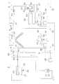
- FIG. 2 is a schematic configuration diagram of the air conditioning system 1.
- the air conditioning system 1 is a device used for air conditioning of a house or a building.
- the air conditioning system 1 is installed in a two-story house 100.
- rooms 101 and 102 are provided on the first floor, and rooms 103 and 104 are provided on the second floor.
- the house 100 is provided with a basement 105.
- the air conditioning system 1 is a so-called duct type air conditioning system.
- the air conditioning system 1 mainly includes an outdoor unit 2, a use unit 3, refrigerant communication pipes 6 and 7 that connect the outdoor unit 2 and the use unit 3, and air conditioned by the use unit 3 in the rooms 101 to 104. And a duct 9 to be sent to.
- the duct 9 is branched into the rooms 101 to 104 and connected to the vents 101a to 104a of the rooms 101 to 104.
- the outdoor unit 2, the indoor unit 4 that is a part of the use unit 3, and the refrigerant communication pipes 6 and 7 constitute a heat pump unit 60 that heats the room by a vapor compression refrigeration cycle.
- the gas furnace unit 5 which is a part of the utilization unit 3 constitutes a separate heat source unit 70 that heats the room by a heat source (here, heat by gas combustion) different from the heat pump unit 60.
- the utilization unit 3 includes both the indoor unit 4 constituting the heat pump unit 60 and the gas furnace unit 5 constituting the separate heat source unit 70.
- the utilization unit 3 takes air in the rooms 101 to 104 into the housing 30 of the utilization unit 3 and is air-conditioned by the heat pump unit 60 (indoor unit 4) and the separate heat source unit 70 (gas furnace unit 5).
- An indoor blower 40 for supplying air into the rooms 101 to 104 is also provided.
- the utilization unit 3 includes a blown air temperature sensor 33 that detects a blown air temperature Trd that is the temperature of air at the air outlet 31 of the housing 30 and a room temperature that is the temperature of air at the air inlet 32 of the housing 30.
- An indoor temperature sensor 34 for detecting Tr is provided.
- the indoor temperature sensor 34 may be provided in the rooms 101 to 104 instead of the usage unit 3.
- the heat pump unit 60 includes the outdoor unit 2, the indoor unit 4 that is a part of the usage unit 3, and the refrigerant communication pipes 6 and 7.
- the outdoor unit 2 and the indoor unit 4 are connected via refrigerant communication pipes 6 and 7.
- the heat pump unit 60 includes the refrigerant circuit 20 in which the outdoor unit 2 and the indoor unit 4 are connected via the refrigerant communication tubes 6 and 7.
- the refrigerant communication pipes 6 and 7 are refrigerant pipes constructed on site when the air conditioning system 1 is installed.
- the indoor unit 4 is provided in the housing 30 of the usage unit 3 installed in the basement 105 of the house 100.
- the indoor unit 4 is connected to the outdoor unit 2 via the refrigerant communication pipes 6 and 7 and constitutes a part of the refrigerant circuit 20.
- the indoor unit 4 mainly has an indoor heat exchanger 42 as a refrigerant radiator that heats air by radiating the refrigerant in the refrigeration cycle.
- the indoor heat exchanger 42 is disposed on the most leeward side in the ventilation path from the air inlet 32 to the air outlet 31 formed in the housing 30 of the utilization unit 3.
- the outdoor unit 2 is installed outside the house 100.
- the outdoor unit 2 is connected to the indoor unit 4 via the refrigerant communication tubes 6 and 7 and constitutes a part of the refrigerant circuit 20.
- the outdoor unit 2 mainly includes a compressor 21, an outdoor heat exchanger 23, and an outdoor expansion valve 24.
- the compressor 21 is a hermetic compressor in which a compression element (not shown) and a compressor motor 22 that rotationally drives the compression element are accommodated in a casing.
- the compressor motor 22 is supplied with electric power via an inverter device (not shown), and the operating capacity can be varied by changing the frequency (that is, the rotation speed) of the inverter device. ing.
- the outdoor heat exchanger 23 is a heat exchanger that functions as a refrigerant evaporator that evaporates refrigerant in the refrigeration cycle by outdoor air.
- An outdoor fan 25 for sending outdoor air to the outdoor heat exchanger 23 is provided in the vicinity of the outdoor heat exchanger 23.
- the outdoor fan 25 is rotationally driven by an outdoor fan motor 26.
- the outdoor expansion valve 24 is a valve that adjusts the flow rate of the refrigerant flowing through the indoor heat exchanger 42 as a refrigerant radiator by reducing the pressure of the refrigerant circulating in the refrigerant circuit 20.
- the outdoor expansion valve 24 is an electric expansion valve connected to the liquid side of the outdoor heat exchanger 23.
- the outdoor unit 2 is provided with an outdoor temperature sensor 27 that detects the temperature of outdoor air outside the house 100 where the outdoor unit 2 is disposed, that is, the outdoor air temperature Ta.
- the outdoor unit 2 has an outdoor side control unit 28 that controls the operation of each unit constituting the outdoor unit 2.
- the outdoor control unit 28 includes a microcomputer provided for controlling the outdoor unit 2, an inverter device that controls the memory and the compressor motor 22, and the like. 38 can exchange control signals and the like.
- the separate heat source unit 70 is configured by the gas furnace unit 5 that is a part of the use unit 3.
- the gas furnace unit 5 is provided in the housing 30 of the usage unit 3 installed in the basement 105 of the house 100.
- the gas furnace unit 5 is a gas combustion type heating apparatus, and mainly includes a fuel gas valve 51, a furnace fan 52, a combustion unit 54, a furnace heat exchanger 55, an air supply pipe 56, and an exhaust pipe 57. And have.
- the fuel gas valve 51 is an electromagnetic valve or the like that can be controlled to open and close, and is provided in a fuel gas supply pipe 58 that extends from the outside of the housing 30 to the combustion unit 54.
- natural gas, petroleum gas, or the like is used as the fuel gas.
- the furnace fan 52 is a fan that generates an air flow in which air is taken into the combustion unit 54 through the air supply pipe 55, and then sent to the furnace heat exchanger 55 and discharged from the exhaust pipe 57.
- the furnace fan 52 is rotationally driven by a furnace fan motor 53.
- the combustion unit 54 is a device that obtains a high-temperature combustion gas by burning a mixed gas of fuel gas and air with a gas burner or the like (not shown).
- the furnace heat exchanger 55 is a heat exchanger that heats air by radiating heat of the combustion gas obtained in the combustion unit 54, and air is radiated by radiating heat from a heat source (here, heat from gas combustion) different from the heat pump unit 60. It functions as a separate heat source radiator that heats.
- the furnace heat exchanger 55 is located on the windward side of the indoor heat exchanger 42 as a refrigerant radiator in the ventilation path from the air inlet 32 to the air outlet 31 formed in the housing 30 of the utilization unit 3. Has been placed.
- the indoor blower 40 is air heated by the indoor heat exchanger 42 as a refrigerant radiator constituting the heat pump unit 60 and the furnace heat exchanger 55 as another heat source radiator constituting the separate heat source unit 70. Is a blower for supplying the air into the rooms 101-104.
- the indoor blower 40 is located on the windward side of both the indoor heat exchanger 42 and the furnace heat exchanger 55 in the ventilation path from the air inlet 32 to the air outlet 31 formed in the housing 30 of the utilization unit 3. Is arranged.
- the indoor blower 40 includes an indoor fan 43 and an indoor fan motor 44 that rotationally drives the indoor fan 43.
- the usage unit 3 includes a usage-side control unit 38 that controls the operation of each unit (the indoor unit 4, the gas furnace unit 5, and the indoor blower 40) constituting the usage unit 3.
- the use-side control unit 38 includes a microcomputer, a memory, and the like provided for controlling the use unit 3 so that control signals and the like can be exchanged with the outdoor unit 2. It has become.
- the utilization side control part 38 of the utilization unit 3 and the outdoor side control part 28 of the outdoor unit 2 comprise the control part 8 which performs operation control of the air conditioning system 1 whole, as shown in FIG. .
- the control unit 8 is connected so as to receive detection signals from various sensors 27, 33, 34 and the like.
- the control unit 8 controls various devices and valves 22, 24, 26, 44, 51, 53 based on these detection signals and the like, that is, controls the operation of the heat pump unit 60 and the separate heat source unit 70.
- the air-conditioning operation heating operation
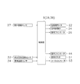
- FIG. 3 is a control block diagram of the air conditioning system 1.
- the high-pressure gas refrigerant sent to the indoor unit 4 of the usage unit 3 is sent to the indoor heat exchanger 42 as a refrigerant radiator.
- the high-pressure gas refrigerant sent to the indoor heat exchanger 42 is condensed by being cooled by performing heat exchange with the indoor air F1 (F2) supplied by the indoor blower 40 in the indoor heat exchanger 42, It becomes a high-pressure liquid refrigerant.
- the high-pressure liquid refrigerant is sent from the indoor unit 4 of the usage unit 3 to the outdoor unit 2 via the liquid refrigerant communication pipe 6.
- the indoor air F3 heated in the indoor heat exchanger 42 is sent from the utilization unit 3 to each of the rooms 101 to 104 through the duct 9 for heating.
- the high-pressure liquid refrigerant sent to the outdoor unit 2 is sent to the outdoor expansion valve 24 and is decompressed by the outdoor expansion valve 24 to become a low-pressure gas-liquid two-phase refrigerant.
- the low-pressure gas-liquid two-phase refrigerant is sent to an outdoor heat exchanger 23 as a refrigerant evaporator.
- the low-pressure gas-liquid two-phase refrigerant sent to the outdoor heat exchanger 23 evaporates by heat exchange with the outdoor air supplied by the outdoor fan 25 in the outdoor heat exchanger 23. It becomes a low-pressure gas refrigerant. This low-pressure gas refrigerant is again sucked into the compressor 21.
- the control unit 8 controls the operating capacity Gr of the compressor 21 and also controls the opening MV of the outdoor expansion valve 24, thereby controlling the indoor spaces in the rooms 101 to 104. Control is performed so that the temperature Tr becomes the target indoor temperature Trs. Specifically, when the temperature difference ⁇ Tr obtained by subtracting the target indoor temperature Trs from the indoor temperature Tr is large, the operating capacity Gr of the compressor 21 (for example, the rotational speed of the compressor motor 22) is increased, and the outdoor expansion valve is increased. The opening degree MV of 24 is increased. Specifically, the control unit 8 increases the operating capacity Gr of the compressor 21 and increases the opening MV of the outdoor expansion valve 24 when the indoor temperature difference ⁇ Tr obtained by subtracting the target indoor temperature Trs from the indoor temperature Tr increases. When the indoor temperature difference ⁇ Tr is reduced, control is performed to reduce the operating capacity Gr of the compressor 21 and the opening degree MV of the outdoor expansion valve 24.
- ⁇ Separate heat source heating operation In the separate heat source heating operation, the fuel gas is supplied to the combustion unit 54 by opening the fuel gas valve 51, and combustion is performed with the air taken into the gas furnace unit 5 of the utilization unit 3 by the furnace fan 52 via the air supply pipe 56. Combustion is performed by mixing and igniting in the section 54 to generate high-temperature combustion gas.
- the high-temperature combustion gas generated in the combustion unit 54 is sent to a furnace heat exchanger 55 as a separate heat source radiator.
- the high-temperature combustion gas sent to the furnace heat exchanger 55 is cooled by exchanging heat with the indoor air F1 supplied by the indoor blower 40 in the furnace heat exchanger 55 to become low-temperature combustion gas.
- This low-temperature combustion gas is discharged from the gas furnace unit 5 of the utilization unit 3 via the exhaust pipe 57.
- the indoor air F2 (F3) heated in the furnace heat exchanger 55 is sent from the utilization unit 3 to each of the rooms 101 to 104 through the duct 9 to be heated.
- the control unit 8 controls the indoor temperature Tr in the rooms 101 to 104 to become the target indoor temperature Trs by controlling the fuel gas valve 51 to open and close. Specifically, the control unit 8 opens the fuel gas valve 51 when the indoor temperature difference ⁇ Tr obtained by subtracting the target indoor temperature Trs from the indoor temperature Tr increases, and closes the fuel gas valve 51 when the indoor temperature difference ⁇ Tr decreases. Control.
- the heat pump heating operation when switching from the heat pump heating operation to the separate heat source heating operation, the heat pump heating operation is performed in order to improve the comfort and energy saving with appropriate switching timing.
- the heat pump heating operation is switched to the separate heat source heating operation. Yes.
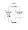
- FIG. 4 is a flowchart showing a switching operation between the heat pump heating operation and the separate heat source heating operation.
- the switching operation between the heat pump heating operation and the separate heat source heating operation is performed by the control unit 8.
- the first switching condition is a determination condition as to whether or not switching from the heat pump heating operation to the separate heat source heating operation is performed.
- the outside air temperature Ta during the heat pump heating operation reaches the first switching outside air temperature Tas1 or less, and the heating capacity by the heat pump unit 60 reaches the upper limit.
- whether or not the heating capacity of the heat pump unit 60 has reached the upper limit depends on whether the temperature difference ⁇ Tr obtained by subtracting the target indoor temperature Trs from the indoor temperature Tr reaches the first switching indoor temperature difference ⁇ Trs1 or more, and the heat pump unit 60 Judgment is made based on whether or not the operating capacity of the component equipment has reached the upper limit.
- whether or not the operating capacity of the devices constituting the heat pump unit 60 has reached the upper limit depends on whether the operating capacity Gr of the compressor 21 (for example, the rotational speed of the compressor motor 22) is the upper limit capacity Grs1 (for example, the upper limit). The number of rotations) and / or whether the degree of opening MV of the outdoor expansion valve 24 has reached the upper limit degree MVs1.
- whether or not the operating capacity of the heat pump unit 60 has reached the upper limit may be determined based on operating capacities of devices other than the compressor 21 and the outdoor expansion valve 24. Further, the temperature Trd of the indoor air after being heated by the indoor heat exchanger 42 as the refrigerant radiator and the flow rate Ga of the indoor air supplied to the room (here, the rooms 101 to 104) by the indoor blower 40. The heating capacity Qa of the heat pump unit 60 may be calculated.
- the temperature Tr of the indoor air before being heated by the indoor heat exchanger 42 as the refrigerant radiator is subtracted from the temperature Trd of the indoor air after being heated by the indoor heat exchanger 42 as the refrigerant radiator, Is multiplied by the flow rate Ga of the indoor air calculated from the rotational speed of the indoor fan motor 44 of the indoor blower 40, etc., so that the amount of exchange heat in the indoor heat exchanger 42 (that is, heating of the heat pump unit 60) is multiplied.
- the capacity Qa) may be calculated to determine whether or not the heating capacity Qa has reached the upper limit value Qas1.
- step ST2 when it determines with satisfy
- the first switching condition is satisfied in step ST2
- the outside air temperature Tam when the heat pump heating operation is switched to the separate heat source heating operation is stored in the memory of the control unit 8.
- the heat pump heating operation in step ST1 is continued.
- switching from the heat pump heating operation to the separate heat source heating operation can be performed at an appropriate timing, and comfort and energy saving can be improved.
- the second switching condition is a determination condition as to whether or not switching from the separate heat source heating operation to the heat pump heating operation is performed.
- the outside air temperature Ta during the separate heat source heating operation reaches or exceeds the second switching outside air temperature Tas2.
- the second switching outside air temperature Tas2 is the outside air temperature Tam when the first switching condition is satisfied in Step ST2, that is, when the heat pump heating operation is switched to the separate heat source heating operation (here, the memory of the control unit 8). Is stored on the basis of). Specifically, it is set to a value obtained by adding a predetermined temperature ⁇ Ta to the outside air temperature Tam when the heat pump heating operation is switched to the separate heat source heating operation.
- the second switching outside air temperature Tas2 when switching from the separate heat source heating operation to the heat pump heating operation is based on the outside air temperature Tam in which it is considered whether the heating capacity by the heat pump unit 60 has reached the upper limit. It is determined and used when switching from the separate heat source heating operation to the heat pump heating operation.
- step ST4 when it determines with satisfy
- switching from the separate heat source heating operation to the heat pump heating operation can be performed at an appropriate timing, and comfort and energy saving can be improved.
- the first switching outside air temperature Tas1 used when switching from the heat pump heating operation to the separate heat source heating operation is a fixed value, but is not limited to this.
- the control unit 8 when the control unit 8 stores the outside air temperature Tam when the heat pump heating operation is switched to the separate heat source heating operation in step ST2, the first switching outside air temperature Tas1 is set to the outside air temperature. It may be updated when replaced with Tam and used when determining whether or not the first switching condition is satisfied.
- the first switching outside air temperature Tas1 used when switching from the heat pump heating operation to the separate heat source heating operation is taken into consideration whether or not the heating capacity by the heat pump unit 60 has reached the upper limit in step ST2. It can be updated to the outside air temperature Tam and used when switching from the next heat pump heating operation to another heat source heating operation.
- the first switching outside air temperature Tas1 used for switching from the heat pump heating operation to the separate heat source heating operation can be set to an appropriate value in consideration of the installation conditions and the operating conditions of the air conditioning system 1. it can.
- the heating capacity by the heat pump unit 60 reaches the upper limit together with the condition that the outside air temperature Ta reaches the first switching outside air temperature Tas1 or less.
- the conditions to reach are added, it is not limited to this.
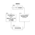
- control unit 8 also determines that the outside air temperature Ta has reached the first switching outside air temperature Tas1 and the coefficient of performance COP of the heat pump unit 60 has reached the lower limit in step ST2. You may make it determine with satisfy
- the coefficient of performance COP may be calculated in various ways.
- the temperature Trd of the indoor air after being heated by the indoor heat exchanger 42 as a refrigerant radiator and the indoor fan (here Then, the heating capacity Qa of the heat pump unit 60 is obtained from the flow rate Ga of the indoor air supplied to the rooms 101 to 104), and this heating capacity Qa is divided by the power consumption Wc of the compressor 21, thereby A coefficient of performance COP can be calculated to determine whether the coefficient of performance COP has reached the lower limit COPas1.
- FIG. 6 in the switching operation of the modification A (see FIG. 5), it is determined whether or not the coefficient of performance COP has reached the lower limit.
- the switching operation in the above embodiment see FIG. 4). In the above, it may be determined whether or not the coefficient of performance COP has reached the lower limit.
- switching from the heat pump heating operation to the separate heat source heating operation can be performed at a timing in consideration of the operation efficiency of the heat pump unit 60.
- the first switching lower limit outside air temperature Tasm is set to a temperature value sufficiently lower than the outside air temperature predicted as the first switching outside air temperature Tas1.
- step ST4 when the outside air temperature Ta reaches the second switching upper limit outside air temperature Tasx higher than the second switching outside air temperature Tas2 in the second switching condition, it is determined whether or not the second switching condition is satisfied. Without switching from the separate heat source heating operation to the heat pump heating operation.
- the second switching upper limit outside air temperature Tasx is set to a temperature value sufficiently higher than the outside air temperature predicted as the second switching outside air temperature Tas2.
- FIG. 7 in the switching operation of the embodiment (see FIG. 4), it is determined whether or not the first switching lower limit outside air temperature Tasm has been reached or not, and whether or not the second switching upper limit outside air temperature Tasx has been reached.
- the switching operations of the modified examples A and B see FIGS. 5 and 6
- the gas furnace unit 5 constituting the separate heat source unit 70 (that is, the furnace heat exchanger 55 as a separate heat source radiator) is used as the indoor unit 4 constituting the heat pump unit 60.
- positions in the windward side namely, the indoor heat exchanger 42 as a refrigerant
- the gas furnace unit 5 as the separate heat source unit 70 (that is, the furnace heat exchanger 55 as the separate heat source radiator) is used as the indoor unit 4 as the heat pump unit 60 (that is, as the refrigerant radiator).
- the indoor heat exchanger 42) may be arranged on the leeward side.
- the gas furnace unit 5 constituting the separate heat source unit 70 and the indoor unit 4 constituting the heat pump unit 60 may be provided separately.
- various devices and sensors such as the indoor blower 40 that are provided in common to both the gas furnace unit 5 and the indoor unit 4 in the above-described embodiment and its modifications are used as the gas furnace unit 5 and the indoor unit. 4 must be provided on both.
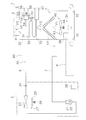
- FIGS. 11 and 12 a configuration in which a plurality (two in this case) of usage units 3 (indoor units 4) are connected to the outdoor unit 2 via refrigerant communication pipes 6 and 7.
- one usage unit 3 may be used for air conditioning of the rooms 103 and 104
- the other usage unit 3 may be used for air conditioning of the rooms 101 and 102.
- FIG. 12 the details of one usage unit 3 are shown, and for the other usage unit 3, only the indoor heat exchanger 42 as a refrigerant radiator constituting the heat pump unit 60 is shown.
- the usage units 3 corresponding to a room used for air conditioning or the vicinity thereof are provided instead of the basement 105.
- the usage units 3 corresponding to the rooms 101 to 104 are provided, the usage units 3 of a type such as floor installation, wall installation, ceiling installation, etc. are provided in the rooms 101 to 104 instead of the duct type. May be. Also, when the use units 3 are provided in the respective rooms 101 to 104, the gas furnace unit 5 constituting the room-specific heat source unit 70 and the indoor unit 4 constituting the heat pump unit 60 are separated from each other as in the modification E. It may be provided at a stand.
- the heat pump unit 60 has the refrigerant circuit 20 dedicated to heating.
- the refrigerant circuit 20 is provided with a four-way switching valve or the like so that the refrigerant circulation direction can be switched.
- the cooling operation may also be possible.
- the gas furnace unit 5 which uses the combustion of fuel gas as a heat source is employ
- adopted as the separate heat source part 70 it is not limited to this.
- any heat source other than the heat pump unit 60 such as a hot water boiler or an electric heater can be used as the separate heat source unit 70.
- the present invention is widely applicable to an air conditioning system having a heat pump unit that heats a room by a vapor compression refrigeration cycle and a separate heat source part that heats the room by a heat source different from the heat pump unit. is there.
Landscapes
- Engineering & Computer Science (AREA)
- Combustion & Propulsion (AREA)
- General Engineering & Computer Science (AREA)
- Mechanical Engineering (AREA)
- Chemical & Material Sciences (AREA)
- Physics & Mathematics (AREA)
- Thermal Sciences (AREA)
- Signal Processing (AREA)
- Mathematical Physics (AREA)
- Fuzzy Systems (AREA)
- Computer Hardware Design (AREA)
- Fluid Mechanics (AREA)
- Air Conditioning Control Device (AREA)
Abstract
空気調和システム(1)の制御部(8)は、ヒートポンプ部(60)によって室内の暖房を行うヒートポンプ暖房運転を行っている際に、外気温度が第1切換外気温度に達し、かつ、ヒートポンプ部による暖房能力が上限に達する第1切換条件を満たす場合に、ヒートポンプ暖房運転から別熱源部(70)によって室内の暖房を行う別熱源暖房運転に切り換える。
Description
本発明は、空気調和システム、特に、蒸気圧縮式の冷凍サイクルによって室内の暖房を行うヒートポンプ部と、ヒートポンプ部とは別の熱源によって室内の暖房を行う別熱源部とを有する空気調和システムに関する。
従来より、蒸気圧縮式の冷凍サイクルによって室内の暖房を行うヒートポンプ部と、ヒートポンプ部とは別の熱源であるガスファーネスによって室内の暖房を行う別熱源部とを有する空気調和システムがある。そして、このような空気調和システムとして、特許文献1(特開昭64-54160号公報)に示すような、外気温度の低下によって、ヒートポンプ部による暖房運転(以下、「ヒートポンプ暖房運転」とする)を、別熱源部による暖房運転(以下、「別熱源暖房運転」とする)に切り換え、外気温度の上昇によって、別熱源暖房運転をヒートポンプ暖房運転に切り換えるものがある。
上記特許文献1におけるヒートポンプ暖房運転から別熱源暖房運転への切り換え手法では、室内の空調負荷(暖房負荷)が大きい場合には、ヒートポンプ暖房運転から別熱源暖房運転への切り換えが遅れて室内温度が低下するおそれがあり、また、室内の空調負荷(暖房負荷)が小さい場合には、ヒートポンプ暖房運転から別熱源暖房運転への切り換えが早すぎて省エネ性が損なわれるおそれがある。これに対して、空気調和システムの設置条件などに応じて、ヒートポンプ暖房運転から別熱源暖房運転に切り換える外気温度を適切に設定することも考えられるが、その設定は容易ではない上に、その作業工数が増加してしまう。
本発明の課題は、ヒートポンプ部と別熱源部とを備えた空気調和システムにおいて、ヒートポンプ暖房運転から別熱源暖房運転に切り換える際に、切り換えのタイミングを適切なものとして快適性及び省エネ性を向上させることにある。
第1の観点にかかる空気調和システムは、蒸気圧縮式の冷凍サイクルによって室内の暖房を行うヒートポンプ部と、ヒートポンプ部とは別の熱源によって室内の暖房を行う別熱源部と、ヒートポンプ部及び別熱源部の動作を制御する制御部と、を有している。そして、ここでは、制御部は、ヒートポンプ部によって室内の暖房を行うヒートポンプ暖房運転を行っている際に、外気温度が第1切換外気温度に達し、かつ、ヒートポンプ部による暖房能力が上限に達する第1切換条件を満たす場合に、ヒートポンプ暖房運転から別熱源部によって室内の暖房を行う別熱源暖房運転に切り換える。
ここでは、上記のように、ヒートポンプ暖房運転から別熱源暖房運転に切り換える際に、外気温度だけでなく、ヒートポンプ部による暖房能力が上限に達しているかどうかも考慮することができる。
これにより、ここでは、ヒートポンプ暖房運転から別熱源暖房運転への切り換えを適切なタイミングで行えるようになり、快適性及び省エネ性を向上させることができる。
第2の観点にかかる空気調和システムは、第1の観点にかかる空気調和システムにおいて、制御部が、ヒートポンプ暖房運転から別熱源暖房運転に切り換えた際の外気温度に基づいて、別熱源暖房運転からヒートポンプ暖房運転に切り換えるための第2切換条件としての第2切換外気温度を決定する。
ここでは、上記のように、別熱源暖房運転からヒートポンプ暖房運転に切り換える際の第2切換外気温度を、ヒートポンプ部による暖房能力が上限に達しているかどうかが考慮された外気温度に基づいて決定して、別熱源暖房運転からヒートポンプ暖房運転への切り換えの際に使用することができる。
これにより、ここでは、別熱源暖房運転からヒートポンプ暖房運転への切り換えも適切なタイミングで行えるようになり、快適性及び省エネ性を向上させることができる。
第3の観点にかかる空気調和システムは、第1又は第2の観点にかかる空気調和システムにおいて、制御部が、ヒートポンプ暖房運転から別熱源暖房運転に切り換えた際の外気温度を記憶して第1切換外気温度を更新し、次に第1切換条件を満たすかどうかを判定する際に使用する。
ここでは、上記のように、ヒートポンプ暖房運転から別熱源暖房運転に切り換える際に使用される第1切換外気温度を、ヒートポンプ部による暖房能力が上限に達しているかどうかが考慮された外気温度に更新して、次のヒートポンプ暖房運転から別熱源暖房運転への切り換えに使用することができる。
これにより、ここでは、ヒートポンプ暖房運転から別熱源暖房運転への切り換えに使用される第1切換外気温度を、空気調和システムの設置条件や運転状況を考慮した適切な値に設定することができる。
第4の観点にかかる空気調和システムは、第1~第3の観点にかかる空気調和システムのいずれかにおいて、制御部が、室内温度から目標室内温度を差し引いた温度差が第1切換室内温度差以上に達し、かつ、ヒートポンプ部を構成する機器の運転容量が上限に達している場合に、ヒートポンプ部による暖房能力が上限に達しているものと判定する。
ここでは、上記のように、ヒートポンプ部による暖房能力が上限に達しているかどうかの判定を、室内温度と、ヒートポンプ部を構成する機器の運転容量に基づいて判定するようにしている。
これにより、ここでは、ヒートポンプ部による暖房能力が上限に達しているかどうかを適切に判定することができる。
第5の観点にかかる空気調和システムは、第1~第4の観点にかかる空気調和システムのいずれかにおいて、制御部が、外気温度が第1切換外気温度に達し、かつ、ヒートポンプ部の成績係数が下限に達している場合にも、第1切換条件を満たすものと判定する。
ここでは、上記のように、ヒートポンプ暖房運転から別熱源暖房運転に切り換える際に、ヒートポンプ部の成績係数が下限に達しているかどうかも考慮することができる。
これにより、ここでは、ヒートポンプ暖房運転から別熱源暖房運転への切り換えをヒートポンプ部の運転効率を考慮したタイミングでも行うことができる。
以下、本発明にかかる空気調和システムの実施形態について、図面に基づいて説明する。尚、本発明にかかる空気調和システムの実施形態の具体的な構成は、下記の実施形態及びその変形例に限られるものではなく、発明の要旨を逸脱しない範囲で変更可能である。
(1)空気調和システムの構成
<全体>
図1は、本発明の一実施形態にかかる空気調和システム1の配置を示す模式図である。図2は、空気調和システム1の概略構成図である。空気調和システム1は、住宅やビルの空調に使用される装置である。ここでは、空気調和システム1は、2階建て構造の住宅100に設置されている。住宅100には、1階に部屋101、102が設けられ、2階に部屋103、104が設けられている。また、住宅100には、地下室105が設けられている。
<全体>
図1は、本発明の一実施形態にかかる空気調和システム1の配置を示す模式図である。図2は、空気調和システム1の概略構成図である。空気調和システム1は、住宅やビルの空調に使用される装置である。ここでは、空気調和システム1は、2階建て構造の住宅100に設置されている。住宅100には、1階に部屋101、102が設けられ、2階に部屋103、104が設けられている。また、住宅100には、地下室105が設けられている。
空気調和システム1は、いわゆるダクト式の空気調和システムである。空気調和システム1は、主として、室外ユニット2と、利用ユニット3と、室外ユニット2と利用ユニット3とを接続する冷媒連絡管6、7と、利用ユニット3で空調された空気を部屋101~104に送るダクト9と、を有している。ダクト9は、部屋101~104に分岐されて、各部屋101~104の通風口101a~104aに接続されている。
ここで、室外ユニット2、利用ユニット3の一部である室内ユニット4、及び、冷媒連絡管6、7は、蒸気圧縮式の冷凍サイクルによって室内の暖房を行うヒートポンプ部60を構成している。また、利用ユニット3の一部であるガスファーネスユニット5は、ヒートポンプ部60とは別の熱源(ここでは、ガス燃焼による熱)によって室内の暖房を行う別熱源部70を構成している。このように、ここでは、利用ユニット3は、ヒートポンプ部60を構成する室内ユニット4、及び、別熱源部70を構成するガスファーネスユニット5の両方を有している。また、利用ユニット3は、利用ユニット3の筐体30内に部屋101~104内の空気を取り込んで、ヒートポンプ部60(室内ユニット4)や別熱源部70(ガスファーネスユニット5)で空調された空気を部屋101~104内に供給するための室内送風機40も有している。また、利用ユニット3には、筐体30の空気出口31における空気の温度である吹出空気温度Trdを検出する吹出空気温度センサ33と、筐体30の空気入口32における空気の温度である室内温度Trを検出する室内温度センサ34とが設けられている。尚、室内温度センサ34は、利用ユニット3ではなく、部屋101~104内に設けられていてもよい。
<ヒートポンプ部>
ヒートポンプ部60は、上記のように、室外ユニット2、利用ユニット3の一部である室内ユニット4、及び、冷媒連絡管6、7によって構成されている。ここで、室外ユニット2と室内ユニット4とは、冷媒連絡管6、7を介して接続されている。すなわち、ヒートポンプ部60は、冷媒回路20は、室外ユニット2と、室内ユニット4とが冷媒連絡管6、7を介して接続されることによって構成されている。ここで、冷媒連絡管6、7は、空気調和システム1を設置する際に、現地にて施工される冷媒管である。
ヒートポンプ部60は、上記のように、室外ユニット2、利用ユニット3の一部である室内ユニット4、及び、冷媒連絡管6、7によって構成されている。ここで、室外ユニット2と室内ユニット4とは、冷媒連絡管6、7を介して接続されている。すなわち、ヒートポンプ部60は、冷媒回路20は、室外ユニット2と、室内ユニット4とが冷媒連絡管6、7を介して接続されることによって構成されている。ここで、冷媒連絡管6、7は、空気調和システム1を設置する際に、現地にて施工される冷媒管である。
室内ユニット4は、ここでは、住宅100の地下室105に設置された利用ユニット3の筐体30内に設けられている。室内ユニット4は、冷媒連絡管6、7を介して室外ユニット2に接続されており、冷媒回路20の一部を構成している。室内ユニット4は、主として、冷凍サイクルにおける冷媒の放熱によって空気を加熱する冷媒放熱器としての室内熱交換器42を有している。ここでは、室内熱交換器42は、利用ユニット3の筐体30に形成された空気入口32から空気出口31までの通風路内の最も風下側に配置されている。
室外ユニット2は、住宅100の屋外に設置されている。室外ユニット2は、冷媒連絡管6、7を介して室内ユニット4に接続されており、冷媒回路20の一部を構成している。室外ユニット2は、主として、圧縮機21と、室外熱交換器23と、室外膨張弁24とを有している。圧縮機21は、ケーシング内に図示しない圧縮要素及び圧縮要素を回転駆動する圧縮機モータ22が収容された密閉型圧縮機である。圧縮機モータ22は、図示しないインバータ装置を介して電力が供給されるようになっており、インバータ装置の周波数(すなわち、回転数)を変化させることによって、運転容量を可変することが可能になっている。室外熱交換器23は、室外空気によって冷凍サイクルにおける冷媒を蒸発させる冷媒蒸発器として機能する熱交換器である。室外熱交換器23の近傍には、室外熱交換器23に室外空気を送るための室外ファン25が設けられている。室外ファン25は、室外ファンモータ26によって回転駆動されるようになっている。室外膨張弁24は、冷媒回路20を循環する冷媒を減圧して冷媒放熱器としての室内熱交換器42を流れる冷媒の流量を調節する弁である。ここで、室外膨張弁24は、室外熱交換器23の液側に接続された電動膨張弁である。また、室外ユニット2には、室外ユニット2が配置される住宅100の屋外の室外空気の温度、すなわち、外気温度Taを検出する室外温度センサ27が設けられている。また、室外ユニット2は、室外ユニット2を構成する各部の動作を制御する室外側制御部28を有している。そして、室外側制御部28は、室外ユニット2の制御を行うために設けられたマイクロコンピュータ、メモリや圧縮機モータ22を制御するインバータ装置等を有しており、利用ユニット3の利用側制御部38との間で制御信号等のやりとりを行うことができるようになっている。
<別熱源部>
別熱源部70は、上記のように、利用ユニット3の一部であるガスファーネスユニット5によって構成されている。
別熱源部70は、上記のように、利用ユニット3の一部であるガスファーネスユニット5によって構成されている。
ガスファーネスユニット5は、ここでは、住宅100の地下室105に設置された利用ユニット3の筐体30内に設けられている。ここでは、ガスファーネスユニット5は、ガス燃焼式暖房装置であり、主として、燃料ガス弁51と、ファーネスファン52と、燃焼部54と、ファーネス熱交換器55と、給気管56と、排気管57とを有している。燃料ガス弁51は、開閉制御が可能な電磁弁等からなり、筐体30外から燃焼部54まで延びる燃料ガス供給管58に設けられている。ここで、燃料ガスとしては、天然ガスや石油ガス等が使用される。ファーネスファン52は、給気管55を通じて燃焼部54に空気を取り込んで、その後、ファーネス熱交換器55に空気を送り、排気管57から排出するという空気の流れを生成するファンである。ファーネスファン52は、ファーネスファンモータ53によって回転駆動されるようになっている。燃焼部54は、ガスバーナ等(図示せず)によって燃料ガスと空気との混合ガスを燃焼させて高温の燃焼ガスを得る機器である。ファーネス熱交換器55は、燃焼部54で得られた燃焼ガスの放熱によって空気を加熱する熱交換器であり、ヒートポンプ部60とは別の熱源(ここでは、ガス燃焼による熱)の放熱によって空気を加熱する別熱源放熱器として機能するものである。ここでは、ファーネス熱交換器55は、利用ユニット3の筐体30に形成された空気入口32から空気出口31までの通風路内において、冷媒放熱器としての室内熱交換器42よりも風上側に配置されている。
<室内送風機>
室内送風機40は、上記のように、ヒートポンプ部60を構成する冷媒放熱器としての室内熱交換器42や別熱源部70を構成する別熱源放熱器としてのファーネス熱交換器55によって加熱される空気を部屋101~104内に供給するための送風機である。ここでは、室内送風機40は、利用ユニット3の筐体30に形成された空気入口32から空気出口31までの通風路内において、室内熱交換器42及びファーネス熱交換器55の両方よりも風上側に配置されている。室内送風機40は、室内ファン43と、室内ファン43を回転駆動する室内ファンモータ44とを有している。
室内送風機40は、上記のように、ヒートポンプ部60を構成する冷媒放熱器としての室内熱交換器42や別熱源部70を構成する別熱源放熱器としてのファーネス熱交換器55によって加熱される空気を部屋101~104内に供給するための送風機である。ここでは、室内送風機40は、利用ユニット3の筐体30に形成された空気入口32から空気出口31までの通風路内において、室内熱交換器42及びファーネス熱交換器55の両方よりも風上側に配置されている。室内送風機40は、室内ファン43と、室内ファン43を回転駆動する室内ファンモータ44とを有している。
<制御部>
利用ユニット3は、利用ユニット3を構成する各部(室内ユニット4、ガスファーネスユニット5、及び、室内送風機40)の動作を制御する利用側制御部38を有している。そして、利用側制御部38は、利用ユニット3の制御を行うために設けられたマイクロコンピュータやメモリ等を有しており、室外ユニット2との間で制御信号等のやりとりを行うことができるようになっている。
利用ユニット3は、利用ユニット3を構成する各部(室内ユニット4、ガスファーネスユニット5、及び、室内送風機40)の動作を制御する利用側制御部38を有している。そして、利用側制御部38は、利用ユニット3の制御を行うために設けられたマイクロコンピュータやメモリ等を有しており、室外ユニット2との間で制御信号等のやりとりを行うことができるようになっている。
そして、利用ユニット3の利用側制御部38と、室外ユニット2の室外側制御部28とは、図2に示すように、空気調和システム1全体の運転制御を行う制御部8を構成している。制御部8は、図3に示されるように、各種センサ27、33、34等の検出信号を受けることができるように接続されている。そして、制御部8は、これらの検出信号等に基づいて各種機器及び弁22、24、26、44、51、53を制御すること、すなわち、ヒートポンプ部60及び別熱源部70の動作を制御することによって、空調運転(暖房運転)を行うように構成されている。ここでは、制御部8は、ヒートポンプ部60によって部屋101~104内の暖房を行うヒートポンプ暖房運転と、別熱源部70によって部屋101~104内の暖房を行う別熱源暖房運転と、を適宜切り換えて行いつつ、部屋101~104内の室内温度Trが目標室内温度Trsになるように制御する。ここで、図3は、空気調和システム1の制御ブロック図である。
(2)空気調和システムの基本動作
次に、空気調和システム1の空調運転(暖房運転)の基本動作について、図1~図3を用いて説明する。上記のように、空気調和システム1の暖房運転には、上記のように、ヒートポンプ部60によって室内の暖房を行うヒートポンプ暖房運転と、別熱源部70によって室内の暖房を行う別熱源暖房運転と、がある。
次に、空気調和システム1の空調運転(暖房運転)の基本動作について、図1~図3を用いて説明する。上記のように、空気調和システム1の暖房運転には、上記のように、ヒートポンプ部60によって室内の暖房を行うヒートポンプ暖房運転と、別熱源部70によって室内の暖房を行う別熱源暖房運転と、がある。
<ヒートポンプ暖房運転>
ヒートポンプ暖房運転においては、冷媒回路20内の冷媒が圧縮機21に吸入されて圧縮されて高圧のガス冷媒となる。この高圧のガス冷媒は、ガス冷媒連絡管7を経由して、室外ユニット2から利用ユニット3の室内ユニット4に送られる。
ヒートポンプ暖房運転においては、冷媒回路20内の冷媒が圧縮機21に吸入されて圧縮されて高圧のガス冷媒となる。この高圧のガス冷媒は、ガス冷媒連絡管7を経由して、室外ユニット2から利用ユニット3の室内ユニット4に送られる。
利用ユニット3の室内ユニット4に送られた高圧のガス冷媒は、冷媒放熱器としての室内熱交換器42に送られる。室内熱交換器42に送られた高圧のガス冷媒は、室内熱交換器42において、室内送風機40によって供給される室内空気F1(F2)と熱交換を行って冷却されることによって凝縮して、高圧の液冷媒となる。この高圧の液冷媒は、液冷媒連絡管6を経由して、利用ユニット3の室内ユニット4から室外ユニット2に送られる。一方、室内熱交換器42において加熱された室内空気F3は、ダクト9を通じて利用ユニット3から各部屋101~104に送られて、暖房が行われる。
室外ユニット2に送られた高圧の液冷媒は、室外膨張弁24に送られ、室外膨張弁24によって減圧されて、低圧の気液二相状態の冷媒となる。この低圧の気液二相状態の冷媒は、冷媒蒸発器としての室外熱交換器23に送られる。室外熱交換器23に送られた低圧の気液二相状態の冷媒は、室外熱交換器23において、室外ファン25によって供給される室外空気と熱交換を行って加熱されることによって蒸発して、低圧のガス冷媒となる。この低圧のガス冷媒は、再び、圧縮機21に吸入される。
そして、上記のヒートポンプ暖房運転において、制御部8は、圧縮機21の運転容量Grを制御することによって、また、室外膨張弁24の開度MVを制御することによって、部屋101~104内の室内温度Trが目標室内温度Trsになるように制御している。具体的には、室内温度Trから目標室内温度Trsを差し引いた温度差ΔTrが大きい場合には、圧縮機21の運転容量Gr(例えば、圧縮機モータ22の回転数)を大きくし、室外膨張弁24の開度MVを大きくする。具体的には、制御部8は、室内温度Trから目標室内温度Trsを差し引いた室内温度差ΔTrが大きくなると、圧縮機21の運転容量Grを大きくし、室外膨張弁24の開度MVを大きくし、室内温度差ΔTrが小さくなると、圧縮機21の運転容量Grを小さくし、室外膨張弁24の開度MVを小さくする制御を行う。
<別熱源暖房運転>
別熱源暖房運転においては、燃料ガス弁51を開けることによって燃焼部54に燃料ガスを供給し、ファーネスファン52によって給気管56を経由して利用ユニット3のガスファーネスユニット5に取り込まれる空気と燃焼部54内で混合し着火することで燃焼させ、高温の燃焼ガスを生成させる。
別熱源暖房運転においては、燃料ガス弁51を開けることによって燃焼部54に燃料ガスを供給し、ファーネスファン52によって給気管56を経由して利用ユニット3のガスファーネスユニット5に取り込まれる空気と燃焼部54内で混合し着火することで燃焼させ、高温の燃焼ガスを生成させる。
燃焼部54内で生成した高温の燃焼ガスは、別熱源放熱器としてのファーネス熱交換器55に送られる。ファーネス熱交換器55に送られた高温の燃焼ガスは、ファーネス熱交換器55において、室内送風機40によって供給される室内空気F1と熱交換を行って冷却され、低温の燃焼ガスとなる。この低温の燃焼ガスは、排気管57を経由して利用ユニット3のガスファーネスユニット5から排出される。一方、ファーネス熱交換器55において加熱された室内空気F2(F3)は、ダクト9を通じて利用ユニット3から各部屋101~104に送られて、暖房が行われる。
そして、上記の別熱源暖房運転において、制御部8は、燃料ガス弁51を開閉制御することによって、部屋101~104内の室内温度Trが目標室内温度Trsになるように制御している。具体的には、制御部8は、室内温度Trから目標室内温度Trsを差し引いた室内温度差ΔTrが大きくなると、燃料ガス弁51を開け、室内温度差ΔTrが小さくなると、燃料ガス弁51を閉止する制御を行う。
(3)ヒートポンプ暖房運転と別熱源暖房運転との切り換え動作
空気調和システム1では、外気温度Taが非常に低い場合にヒートポンプ暖房運転では室内(ここでは、部屋101~104)の空調負荷(暖房負荷)をカバーできない場合があるため、外気温度Taの低下によって、ヒートポンプ暖房運転を、別熱源暖房運転に切り換え、外気温度Taの上昇によって、別熱源暖房運転をヒートポンプ暖房運転に切り換える動作を行う必要がある。
空気調和システム1では、外気温度Taが非常に低い場合にヒートポンプ暖房運転では室内(ここでは、部屋101~104)の空調負荷(暖房負荷)をカバーできない場合があるため、外気温度Taの低下によって、ヒートポンプ暖房運転を、別熱源暖房運転に切り換え、外気温度Taの上昇によって、別熱源暖房運転をヒートポンプ暖房運転に切り換える動作を行う必要がある。
しかし、単なる外気温度Taの条件だけで切り換える手法では、室内(ここでは、部屋101~104)の空調負荷(暖房負荷)が大きい場合には、ヒートポンプ暖房運転から別熱源暖房運転への切り換えが遅れて室内温度Trが低下するおそれがあり、また、室内の空調負荷(暖房負荷)が小さい場合には、ヒートポンプ暖房運転から別熱源暖房運転への切り換えが早すぎて省エネ性が損なわれるおそれがある。これに対して、空気調和システム1の設置条件などに応じて、ヒートポンプ暖房運転から別熱源暖房運転に切り換える外気温度を適切に設定することも考えられるが、その設定は容易ではない上に、その作業工数が増加してしまう。
そこで、ここでは、ヒートポンプ暖房運転から別熱源暖房運転に切り換える際に、切り換えのタイミングを適切なものとして快適性及び省エネ性を向上させることができるようにするために、ヒートポンプ暖房運転を行っている際に、外気温度Taが第1切換外気温度Tas1に達し、かつ、ヒートポンプ部60による暖房能力が上限に達する第1切換条件を満たす場合に、ヒートポンプ暖房運転から別熱源暖房運転に切り換えるようにしている。
次に、第1切換条件によるヒートポンプ暖房運転から別熱源暖房運転への切り換えを含めたヒートポンプ暖房運転と別熱源暖房運転との切り換え動作について、図1~図4を用いて説明する。ここで、図4は、ヒートポンプ暖房運転と別熱源暖房運転との切り換え動作を示すフローチャートである。尚、ヒートポンプ暖房運転と別熱源暖房運転との切り換え動作は、制御部8によって行われる。
具体的には、まず、空気調和システム1の運転が開始すると、ステップST1のヒートポンプ暖房運転を行う。そして、ステップST1のヒートポンプ暖房運転時においては、ステップST2の第1切換条件を満たすかどうかの判定を行う。この第1切換条件は、ヒートポンプ暖房運転から別熱源暖房運転への切り換えを行うかどうかの判定条件である。ここでは、上記のように、ヒートポンプ暖房運転時における外気温度Taが第1切換外気温度Tas1以下に達し、かつ、ヒートポンプ部60による暖房能力が上限に達することである。ここで、ヒートポンプ部60による暖房能力が上限に達しているかどうかは、室内温度Trから目標室内温度Trsを差し引いた温度差ΔTrが第1切換室内温度差ΔTrs1以上に達し、かつ、ヒートポンプ部60を構成する機器の運転容量が上限に達しているかどうかによって判定する。尚、ここでは、ヒートポンプ部60を構成する機器の運転容量が上限に達しているかどうかは、圧縮機21の運転容量Gr(例えば、圧縮機モータ22の回転数)が上限容量Grs1(例えば、上限回転数)に達しているかどうか、及び/又は、室外膨張弁24の開度MVが上限開度MVs1に達しているかどうかによって判定する。但し、ヒートポンプ部60の運転容量が上限に達しているかどうかを、圧縮機21や室外膨張弁24以外の機器の運転容量によって判定するようにしてもよい。また、冷媒放熱器としての室内熱交換器42によって加熱された後の室内空気の温度Trd、及び、室内送風機40によって室内(ここでは、部屋101~104)に供給される室内空気の流量Gaからヒートポンプ部60の暖房能力Qaを算出してもよい。ここでは、冷媒放熱器としての室内熱交換器42によって加熱された後の室内空気の温度Trdから冷媒放熱器としての室内熱交換器42によって加熱される前の室内空気の温度Trを差し引き、これにより得られた温度差に、室内送風機40の室内ファンモータ44の回転数等から算出した室内空気の流量Gaを乗算することによって、室内熱交換器42における交換熱量(すなわち、ヒートポンプ部60の暖房能力Qa)を算出して、この暖房能力Qaが上限値Qas1に達しているかどうかを判定するようにしてもよい。
このように、ここでは、ヒートポンプ暖房運転から別熱源暖房運転に切り換える際に、外気温度Taだけでなく、ヒートポンプ部60による暖房能力が上限に達しているかどうかも考慮されている。また、ここでは、ヒートポンプ部60による暖房能力が上限に達しているかどうかの判定を、室内温度Trと、ヒートポンプ部60を構成する機器(ここでは、圧縮機21や室外膨張弁24)の運転容量に基づいて判定するようにしている。
そして、ステップST2において、第1切換条件を満たすと判定された場合には、ステップST3の処理に移行、すなわち、ヒートポンプ暖房運転から別熱源暖房運転に切り換える。このとき、ステップST2において第1切換条件を満たした際、すなわち、ヒートポンプ暖房運転から別熱源暖房運転に切り換えた際の外気温度Tamを制御部8のメモリに記憶しておく。一方、ステップST2において、第1切換条件を満たさないと判定された場合には、ステップST1のヒートポンプ暖房運転を継続する。
これにより、ここでは、ヒートポンプ暖房運転から別熱源暖房運転への切り換えを適切なタイミングで行えるようになり、快適性及び省エネ性を向上させることができる。また、ここでは、ヒートポンプ部60による暖房能力が上限に達しているかどうかを適切に判定することができる。
次に、ステップST3の別熱源暖房運転時においては、ステップST4の第2切換条件を満たすかどうかの判定を行う。この第2切換条件は、別熱源暖房運転からヒートポンプ暖房運転への切り換えを行うかどうかの判定条件である。ここでは、別熱源暖房運転時における外気温度Taが第2切換外気温度Tas2以上に達することである。ここで、第2切換外気温度Tas2は、ステップST2において第1切換条件を満たした際、すなわち、ヒートポンプ暖房運転から別熱源暖房運転に切り換えた際の外気温度Tam(ここでは、制御部8のメモリに記憶されている)に基づいて決定されている。具体的には、ヒートポンプ暖房運転から別熱源暖房運転に切り換えた際の外気温度Tamに所定温度ΔTaを加算した値にしている。
このように、ここでは、別熱源暖房運転からヒートポンプ暖房運転に切り換える際の第2切換外気温度Tas2を、ヒートポンプ部60による暖房能力が上限に達しているかどうかが考慮された外気温度Tamに基づいて決定して、別熱源暖房運転からヒートポンプ暖房運転への切り換えの際に使用するようにしている。
そして、ステップST4において、第2切換条件を満たすと判定された場合には、ステップST1の処理に移行、すなわち、別熱源暖房運転からヒートポンプ暖房運転に切り換える。一方、ステップST4において、第2切換条件を満たさないと判定された場合には、ステップST3の別熱源暖房運転を継続する。
これにより、ここでは、別熱源暖房運転からヒートポンプ暖房運転への切り換えも適切なタイミングで行えるようになり、快適性及び省エネ性を向上させることができる。
(4)変形例
<A>
上記実施形態では、ヒートポンプ暖房運転から別熱源暖房運転への切り換えの際に使用される第1切換外気温度Tas1が固定値になっているが、これに限定されるものではない。
<A>
上記実施形態では、ヒートポンプ暖房運転から別熱源暖房運転への切り換えの際に使用される第1切換外気温度Tas1が固定値になっているが、これに限定されるものではない。
例えば、図5に示すように、制御部8が、ステップST2において、ヒートポンプ暖房運転から別熱源暖房運転に切り換えた際の外気温度Tamを記憶する際に、第1切換外気温度Tas1をこの外気温度Tamに置き換えることで更新し、次に第1切換条件を満たすかどうかを判定する際に使用するようにしてもよい。
このように、ここでは、ヒートポンプ暖房運転から別熱源暖房運転に切り換える際に使用される第1切換外気温度Tas1を、ステップST2においてヒートポンプ部60による暖房能力が上限に達しているかどうかが考慮された外気温度Tamに更新して、次のヒートポンプ暖房運転から別熱源暖房運転への切り換えの際に使用することができる。
これにより、ここでは、ヒートポンプ暖房運転から別熱源暖房運転への切り換えに使用される第1切換外気温度Tas1を、空気調和システム1の設置条件や運転状況を考慮した適切な値に設定することができる。
<B>
上記実施形態やその変形例では、ヒートポンプ暖房運転から別熱源暖房運転に切り換える第1切換条件として、外気温度Taが第1切換外気温度Tas1以下に達する条件とともに、ヒートポンプ部60による暖房能力が上限に達する条件を加えるようにしているが、これだけに限定されるものではない。
上記実施形態やその変形例では、ヒートポンプ暖房運転から別熱源暖房運転に切り換える第1切換条件として、外気温度Taが第1切換外気温度Tas1以下に達する条件とともに、ヒートポンプ部60による暖房能力が上限に達する条件を加えるようにしているが、これだけに限定されるものではない。
例えば、図6に示すように、制御部8が、ステップST2において、外気温度Taが第1切換外気温度Tas1に達し、かつ、ヒートポンプ部60の成績係数COPが下限に達している場合にも、第1切換条件を満たすものと判定するようにしてもよい。ここで、成績係数COPは、種々の算出方法が考えられるが、例えば、冷媒放熱器としての室内熱交換器42によって加熱された後の室内空気の温度Trd、及び、室内送風機40によって室内(ここでは、部屋101~104)に供給される室内空気の流量Gaからヒートポンプ部60の暖房能力Qaを得て、この暖房能力Qaを圧縮機21の消費動力Wcで除算することによって、ヒートポンプ部60の成績係数COPを算出して、この成績係数COPが下限値COPas1に達しているかどうかを判定することができる。尚、図6では、変形例A(図5参照)の切り換え動作において、成績係数COPが下限に達しているかどうかの判定を加えるようにしているが、上記実施形態(図4参照)の切り換え動作において、成績係数COPが下限に達しているかどうかの判定を加えるようにしてもよい。
このように、ここでは、ヒートポンプ暖房運転から別熱源暖房運転に切り換える際に、ヒートポンプ部60の成績係数COPが下限に達しているかどうかも考慮することができる。
これにより、ここでは、ヒートポンプ暖房運転から別熱源暖房運転への切り換えをヒートポンプ部60の運転効率を考慮したタイミングでも行うことができる。
<C>
上記実施形態やその変形例において、極端に外気温度Taが低い場合や極端に外気温度Taが高い場合には、ステップST2の第1切換条件を満たすかどうかや、ステップST4の第2切換条件を満たすかどうかを判定することなく、ヒートポンプ暖房運転と別熱源暖房運転との切り換えを行うことが好ましい。
上記実施形態やその変形例において、極端に外気温度Taが低い場合や極端に外気温度Taが高い場合には、ステップST2の第1切換条件を満たすかどうかや、ステップST4の第2切換条件を満たすかどうかを判定することなく、ヒートポンプ暖房運転と別熱源暖房運転との切り換えを行うことが好ましい。
そこで、ここでは、図7に示すように、ステップST2において、外気温度Taが第1切換条件における第1切換外気温度Tas1よりも低い第1切換下限外気温度Tasm以下に達した場合には、第1切換条件を満たすかどうかを判定することなく、ヒートポンプ暖房運転から別熱源暖房運転への切り換えを行う。ここで、第1切換下限外気温度Tasmは、第1切換外気温度Tas1として予測される外気温度よりも十分に低い温度値に設定される。また、ステップST4において、外気温度Taが第2切換条件における第2切換外気温度Tas2よりも高い第2切換上限外気温度Tasx以上に達した場合には、第2切換条件を満たすかどうかを判定することなく、別熱源暖房運転からヒートポンプ暖房運転への切り換えを行う。ここで、第2切換上限外気温度Tasxは、第2切換外気温度Tas2として予測される外気温度よりも十分に高い温度値に設定される。尚、図7では、上記実施形態(図4参照)の切り換え動作において、第1切換下限外気温度Tasm以下に達したかどうかの判定や第2切換上限外気温度Tasx以上に達したかどうかの判定を加えるようにしているが、変形例A、B(図5、図6参照)の切り換え動作において、第1切換下限外気温度Tasm以下に達したかどうかの判定や第2切換上限外気温度Tasx以上に達したかどうかの判定を加えるようにしてもよい。
<D>
上記実施形態やその変形例では、利用ユニット3において、別熱源部70を構成するガスファーネスユニット5(すなわち、別熱源放熱器としてのファーネス熱交換器55)をヒートポンプ部60を構成する室内ユニット4(すなわち、冷媒放熱器としての室内熱交換器42)の風上側に配置しているが、これに限定されるものではない。
上記実施形態やその変形例では、利用ユニット3において、別熱源部70を構成するガスファーネスユニット5(すなわち、別熱源放熱器としてのファーネス熱交換器55)をヒートポンプ部60を構成する室内ユニット4(すなわち、冷媒放熱器としての室内熱交換器42)の風上側に配置しているが、これに限定されるものではない。
例えば、図8に示すように、別熱源部70としてのガスファーネスユニット5(すなわち、別熱源放熱器としてのファーネス熱交換器55)をヒートポンプ部60としての室内ユニット4(すなわち、冷媒放熱器としての室内熱交換器42)の風下側に配置してもよい。
<E>
上記実施形態やその変形例では、別熱源部70を構成するガスファーネスユニット5とヒートポンプ部60を構成する室内ユニット4とが一体の利用ユニット3として構成されているが、これに限定されるものではない。
上記実施形態やその変形例では、別熱源部70を構成するガスファーネスユニット5とヒートポンプ部60を構成する室内ユニット4とが一体の利用ユニット3として構成されているが、これに限定されるものではない。
例えば、図9及び図10に示すように、別熱源部70を構成するガスファーネスユニット5とヒートポンプ部60を構成する室内ユニット4とが別置きになっていてもよい。但し、この場合には、上記実施形態やその変形例でガスファーネスユニット5及び室内ユニット4の両方に共通に設けられていた室内送風機40等の各種機器やセンサを、ガスファーネスユニット5及び室内ユニット4の両方に設ける必要がある。
<F>
上記実施形態やその変形例では、室外ユニット2に対して利用ユニット3(室内ユニット4)が1台接続された構成であるが、これに限定されるものではない。
上記実施形態やその変形例では、室外ユニット2に対して利用ユニット3(室内ユニット4)が1台接続された構成であるが、これに限定されるものではない。
例えば、図11及び図12に示すように、室外ユニット2に対して複数台(ここでは、2台)の利用ユニット3(室内ユニット4)が冷媒連絡管6、7を介して接続された構成にして、一方の利用ユニット3を部屋103、104の空調に使用し、他方の利用ユニット3を部屋101、102の空調に使用してもよい。尚、図12では、一方の利用ユニット3の詳細を図示し、他方の利用ユニット3については、ヒートポンプ部60を構成する冷媒放熱器としての室内熱交換器42のみを図示している。また、室外ユニット2に対して複数台の利用ユニット3を接続する構成を採用する場合には、地下室105ではなく、空調に使用される部屋又はその近傍に対応する利用ユニット3を設けるようにしてもよい。また、各部屋101~104に対応する利用ユニット3を設ける場合には、ダクト式ではなく、各部屋101~104に床置き設置や壁掛け設置、天井設置などの型式の利用ユニット3を設けるようにしてもよい。また、各部屋101~104に利用ユニット3を設ける場合にも、変形例Eと同様に、各部屋別熱源部70を構成するガスファーネスユニット5とヒートポンプ部60を構成する室内ユニット4とを別置きで設けてもよい。
<G>
上記実施形態やその変形例では、ヒートポンプ部60が暖房専用の冷媒回路20を有しているが、冷媒回路20に四路切換弁等を設けて冷媒の循環方向を切り換えることができるようにして、冷房運転も可能な構成にしてもよい。
上記実施形態やその変形例では、ヒートポンプ部60が暖房専用の冷媒回路20を有しているが、冷媒回路20に四路切換弁等を設けて冷媒の循環方向を切り換えることができるようにして、冷房運転も可能な構成にしてもよい。
<H>
上記実施形態やその変形例では、別熱源部70として燃料ガスの燃焼を熱源とするガスファーネスユニット5を採用しているが、これに限定されるものではない。例えば、温水ボイラや電気ヒータなどのように、ヒートポンプ部60とは別の熱源であればどのようなものでも別熱源部70として採用可能である。
上記実施形態やその変形例では、別熱源部70として燃料ガスの燃焼を熱源とするガスファーネスユニット5を採用しているが、これに限定されるものではない。例えば、温水ボイラや電気ヒータなどのように、ヒートポンプ部60とは別の熱源であればどのようなものでも別熱源部70として採用可能である。
本発明は、蒸気圧縮式の冷凍サイクルによって室内の暖房を行うヒートポンプ部と、ヒートポンプ部とは別の熱源によって室内の暖房を行う別熱源部とを有する空気調和システムに対して、広く適用可能である。
1 空気調和システム
8 制御部
60 ヒートポンプ部
70 別熱源部
8 制御部
60 ヒートポンプ部
70 別熱源部
Claims (5)
- 蒸気圧縮式の冷凍サイクルによって室内の暖房を行うヒートポンプ部(60)と、
前記ヒートポンプ部とは別の熱源によって室内の暖房を行う別熱源部(70)と、
前記ヒートポンプ部及び前記別熱源部の動作を制御する制御部(8)と、
を備えており、
前記制御部は、前記ヒートポンプ部によって室内の暖房を行うヒートポンプ暖房運転を行っている際に、外気温度が第1切換外気温度に達し、かつ、前記ヒートポンプ部による暖房能力が上限に達する第1切換条件を満たす場合に、前記ヒートポンプ暖房運転から前記別熱源部によって室内の暖房を行う別熱源暖房運転に切り換える、
空気調和システム(1)。 - 前記制御部(8)は、前記ヒートポンプ暖房運転から前記別熱源暖房運転に切り換えた際の外気温度に基づいて、前記別熱源暖房運転から前記ヒートポンプ暖房運転に切り換えるための第2切換条件としての第2切換外気温度を決定する、
請求項1に記載の空気調和システム(1)。 - 前記制御部(8)は、前記ヒートポンプ暖房運転から前記別熱源暖房運転に切り換えた際の前記外気温度を記憶して前記第1切換外気温度を更新し、
次に前記第1切換条件を満たすかどうかを判定する際に使用する、
請求項1又は2に記載の空気調和システム(1)。 - 前記制御部(8)は、室内温度から目標室内温度を差し引いた温度差が第1切換室内温度差以上に達し、かつ、前記ヒートポンプ部を構成する機器の運転容量が上限に達している場合に、前記ヒートポンプ部による暖房能力が上限に達しているものと判定する、
請求項1~3のいずれか1項に記載の空気調和システム(1)。 - 前記制御部(8)は、外気温度が第1切換外気温度に達し、かつ、前記ヒートポンプ部の成績係数が下限に達している場合にも、前記第1切換条件を満たすものと判定する、
請求項1~4のいずれか1項に記載の空気調和システム(1)。
Priority Applications (3)
| Application Number | Priority Date | Filing Date | Title |
|---|---|---|---|
| CN201580006574.2A CN105940273B (zh) | 2014-02-03 | 2015-01-27 | 空调系统 |
| EP15743681.7A EP3096091B1 (en) | 2014-02-03 | 2015-01-27 | Air-conditioning system |
| US15/115,223 US9927133B2 (en) | 2014-02-03 | 2015-01-27 | Air conditioning system |
Applications Claiming Priority (2)
| Application Number | Priority Date | Filing Date | Title |
|---|---|---|---|
| JP2014-018778 | 2014-02-03 | ||
| JP2014018778A JP5858062B2 (ja) | 2014-02-03 | 2014-02-03 | 空気調和システム |
Publications (1)
| Publication Number | Publication Date |
|---|---|
| WO2015115404A1 true WO2015115404A1 (ja) | 2015-08-06 |
Family
ID=53756977
Family Applications (1)
| Application Number | Title | Priority Date | Filing Date |
|---|---|---|---|
| PCT/JP2015/052153 Ceased WO2015115404A1 (ja) | 2014-02-03 | 2015-01-27 | 空気調和システム |
Country Status (5)
| Country | Link |
|---|---|
| US (1) | US9927133B2 (ja) |
| EP (1) | EP3096091B1 (ja) |
| JP (1) | JP5858062B2 (ja) |
| CN (1) | CN105940273B (ja) |
| WO (1) | WO2015115404A1 (ja) |
Cited By (1)
| Publication number | Priority date | Publication date | Assignee | Title |
|---|---|---|---|---|
| WO2021225213A1 (ko) * | 2020-05-06 | 2021-11-11 | 엘지전자 주식회사 | 공기조화기 시스템 및 그 제어방법 |
Families Citing this family (12)
| Publication number | Priority date | Publication date | Assignee | Title |
|---|---|---|---|---|
| JP5858062B2 (ja) | 2014-02-03 | 2016-02-10 | ダイキン工業株式会社 | 空気調和システム |
| JP6384057B2 (ja) * | 2014-02-03 | 2018-09-05 | ダイキン工業株式会社 | 空調システム |
| JP6281535B2 (ja) | 2015-07-23 | 2018-02-21 | 株式会社デンソー | 中継装置、ecu、及び、車載システム |
| CN106123106A (zh) * | 2016-07-05 | 2016-11-16 | 广东美的暖通设备有限公司 | 一种采暖控制方法、装置及联合采暖系统 |
| ES2934137T3 (es) * | 2016-09-23 | 2023-02-17 | Daikin Ind Ltd | Sistema de aire acondicionado y suministro de agua caliente |
| IT201600119340A1 (it) * | 2016-11-24 | 2018-05-24 | Systema S P A | Apparecchiatura combinata per il condizionamento di ambienti |
| US10465935B2 (en) | 2017-10-20 | 2019-11-05 | Mitsubishi Electric Corporation | Air-conditioning apparatus |
| CN108168046A (zh) * | 2017-12-26 | 2018-06-15 | 珠海格力电器股份有限公司 | 一种空调控制方法及空调 |
| CN108917060A (zh) * | 2018-07-31 | 2018-11-30 | 广东美的暖通设备有限公司 | 制热系统的控制方法及装置、存储介质和制热系统 |
| KR102918929B1 (ko) | 2020-02-25 | 2026-01-27 | 엘지전자 주식회사 | 히트펌프 및 그 동작방법 |
| KR102815172B1 (ko) | 2020-02-25 | 2025-05-29 | 엘지전자 주식회사 | 히트펌프 및 그 동작방법 |
| US12398921B2 (en) * | 2020-08-26 | 2025-08-26 | Carrier Corporation | Heat exchanger baffle assembly with horizontal gap |
Citations (8)
| Publication number | Priority date | Publication date | Assignee | Title |
|---|---|---|---|---|
| US4143707A (en) * | 1977-11-21 | 1979-03-13 | The Trane Company | Air conditioning apparatus including a heat pump |
| JPS6256730A (ja) * | 1985-09-02 | 1987-03-12 | Mitsubishi Electric Corp | 冷暖房装置 |
| JPS6454160A (en) | 1987-08-24 | 1989-03-01 | Mitsubishi Electric Corp | Air conditioner |
| US4860552A (en) * | 1988-12-23 | 1989-08-29 | Honeywell, Inc. | Heat pump fan control |
| JPH05312379A (ja) * | 1992-05-11 | 1993-11-22 | Sanyo Electric Co Ltd | 空気調和機の制御装置 |
| US20090171862A1 (en) * | 2007-12-28 | 2009-07-02 | Johnson Controls Technology Company | Energy control system |
| US20130066472A1 (en) * | 2008-09-15 | 2013-03-14 | Johnson Controls Technology Company | Transition temperature adjustment user interfaces |
| JP2013053845A (ja) * | 2012-11-12 | 2013-03-21 | Mitsubishi Electric Corp | 空気調和システム |
Family Cites Families (15)
| Publication number | Priority date | Publication date | Assignee | Title |
|---|---|---|---|---|
| US3173476A (en) | 1961-07-10 | 1965-03-16 | Carrier Corp | Heat pump |
| US3996998A (en) * | 1974-11-27 | 1976-12-14 | Lennox Industries Inc. | Combination furnace--heat pump unit |
| US4217761A (en) * | 1978-09-28 | 1980-08-19 | Cornaire James L | Heat pump output indicator |
| US4445567A (en) | 1982-02-26 | 1984-05-01 | Honeywell Inc. | Thermostat for control of an add-on heat pump system |
| EP0098787B1 (en) | 1982-07-02 | 1987-01-07 | Carrier Corporation | Method and apparatus for integrating operation of a heat pump and a separate heating source and preventing simultaneous operation of a heat pump and a separate heating source |
| KR900002143B1 (ko) * | 1985-03-29 | 1990-04-02 | 미쯔비시 덴끼 가부시기가이샤 | 덕트식 멀티조온 공조시스템 |
| US6176306B1 (en) * | 1997-07-01 | 2001-01-23 | Robert Gault | Method and device for controlling operation of heat pump |
| US6729390B1 (en) * | 2001-06-01 | 2004-05-04 | Emerson Electric Co. | Control for heat pump with auxiliary heat source |
| US7380588B2 (en) * | 2004-01-12 | 2008-06-03 | Trane International Inc. | Heat pump control system and method of operating to provide automatic backup heating modes |
| US20100090017A1 (en) * | 2008-10-11 | 2010-04-15 | Reza Naghshineh | Hybrid heating system and method |
| US9632490B2 (en) * | 2008-10-27 | 2017-04-25 | Lennox Industries Inc. | System and method for zoning a distributed architecture heating, ventilation and air conditioning network |
| US20120248212A1 (en) | 2011-03-30 | 2012-10-04 | Trane International Inc. | Methods and Systems for Controlling a Hybrid Heating System |
| US9651268B2 (en) * | 2013-03-11 | 2017-05-16 | Rheem Manufacturing Company | Gas fired modular blower control and associated methodology |
| JP6244791B2 (ja) * | 2013-09-30 | 2017-12-13 | ダイキン工業株式会社 | 空調システム |
| JP5858062B2 (ja) | 2014-02-03 | 2016-02-10 | ダイキン工業株式会社 | 空気調和システム |
-
2014
- 2014-02-03 JP JP2014018778A patent/JP5858062B2/ja active Active
-
2015
- 2015-01-27 CN CN201580006574.2A patent/CN105940273B/zh active Active
- 2015-01-27 WO PCT/JP2015/052153 patent/WO2015115404A1/ja not_active Ceased
- 2015-01-27 US US15/115,223 patent/US9927133B2/en active Active
- 2015-01-27 EP EP15743681.7A patent/EP3096091B1/en active Active
Patent Citations (8)
| Publication number | Priority date | Publication date | Assignee | Title |
|---|---|---|---|---|
| US4143707A (en) * | 1977-11-21 | 1979-03-13 | The Trane Company | Air conditioning apparatus including a heat pump |
| JPS6256730A (ja) * | 1985-09-02 | 1987-03-12 | Mitsubishi Electric Corp | 冷暖房装置 |
| JPS6454160A (en) | 1987-08-24 | 1989-03-01 | Mitsubishi Electric Corp | Air conditioner |
| US4860552A (en) * | 1988-12-23 | 1989-08-29 | Honeywell, Inc. | Heat pump fan control |
| JPH05312379A (ja) * | 1992-05-11 | 1993-11-22 | Sanyo Electric Co Ltd | 空気調和機の制御装置 |
| US20090171862A1 (en) * | 2007-12-28 | 2009-07-02 | Johnson Controls Technology Company | Energy control system |
| US20130066472A1 (en) * | 2008-09-15 | 2013-03-14 | Johnson Controls Technology Company | Transition temperature adjustment user interfaces |
| JP2013053845A (ja) * | 2012-11-12 | 2013-03-21 | Mitsubishi Electric Corp | 空気調和システム |
Non-Patent Citations (1)
| Title |
|---|
| See also references of EP3096091A4 |
Cited By (2)
| Publication number | Priority date | Publication date | Assignee | Title |
|---|---|---|---|---|
| WO2021225213A1 (ko) * | 2020-05-06 | 2021-11-11 | 엘지전자 주식회사 | 공기조화기 시스템 및 그 제어방법 |
| US11867418B2 (en) | 2020-05-06 | 2024-01-09 | Lg Electronics Inc. | Air conditioning system and method for controlling air conditioning system |
Also Published As
| Publication number | Publication date |
|---|---|
| US20160341434A1 (en) | 2016-11-24 |
| CN105940273A (zh) | 2016-09-14 |
| CN105940273B (zh) | 2018-05-22 |
| JP5858062B2 (ja) | 2016-02-10 |
| US9927133B2 (en) | 2018-03-27 |
| EP3096091A4 (en) | 2017-04-05 |
| JP2015145759A (ja) | 2015-08-13 |
| EP3096091B1 (en) | 2018-08-29 |
| EP3096091A1 (en) | 2016-11-23 |
Similar Documents
| Publication | Publication Date | Title |
|---|---|---|
| JP5858062B2 (ja) | 空気調和システム | |
| JP5861726B2 (ja) | 空気調和システム | |
| US12066228B2 (en) | Heating, ventilation, and air conditioning control system | |
| AU2012392673B2 (en) | Air conditioning apparatus | |
| US20220404038A1 (en) | Air conditioning system | |
| JP6384057B2 (ja) | 空調システム | |
| US12345434B2 (en) | Air conditioning system | |
| US9410715B2 (en) | Air conditioning apparatus | |
| JP2012141113A (ja) | 空気調和温水機器システム | |
| WO2013145838A1 (ja) | 床暖房装置および温調システム | |
| JP6907653B2 (ja) | 空調システム |
Legal Events
| Date | Code | Title | Description |
|---|---|---|---|
| 121 | Ep: the epo has been informed by wipo that ep was designated in this application |
Ref document number: 15743681 Country of ref document: EP Kind code of ref document: A1 |
|
| WWE | Wipo information: entry into national phase |
Ref document number: 15115223 Country of ref document: US |
|
| NENP | Non-entry into the national phase |
Ref country code: DE |
|
| REEP | Request for entry into the european phase |
Ref document number: 2015743681 Country of ref document: EP |
|
| WWE | Wipo information: entry into national phase |
Ref document number: 2015743681 Country of ref document: EP |