WO2015115508A1 - Système de communication mobile et terminal d'utilisateur - Google Patents
Système de communication mobile et terminal d'utilisateur Download PDFInfo
- Publication number
- WO2015115508A1 WO2015115508A1 PCT/JP2015/052418 JP2015052418W WO2015115508A1 WO 2015115508 A1 WO2015115508 A1 WO 2015115508A1 JP 2015052418 W JP2015052418 W JP 2015052418W WO 2015115508 A1 WO2015115508 A1 WO 2015115508A1
- Authority
- WO
- WIPO (PCT)
- Prior art keywords
- information
- user terminal
- emergency
- resource
- transmission
- Prior art date
- Legal status (The legal status is an assumption and is not a legal conclusion. Google has not performed a legal analysis and makes no representation as to the accuracy of the status listed.)
- Ceased
Links
Images






Classifications
-
- H—ELECTRICITY
- H04—ELECTRIC COMMUNICATION TECHNIQUE
- H04W—WIRELESS COMMUNICATION NETWORKS
- H04W72/00—Local resource management
- H04W72/20—Control channels or signalling for resource management
-
- H—ELECTRICITY
- H04—ELECTRIC COMMUNICATION TECHNIQUE
- H04W—WIRELESS COMMUNICATION NETWORKS
- H04W76/00—Connection management
- H04W76/50—Connection management for emergency connections
-
- H—ELECTRICITY
- H04—ELECTRIC COMMUNICATION TECHNIQUE
- H04W—WIRELESS COMMUNICATION NETWORKS
- H04W28/00—Network traffic management; Network resource management
- H04W28/02—Traffic management, e.g. flow control or congestion control
- H04W28/04—Error control
-
- H—ELECTRICITY
- H04—ELECTRIC COMMUNICATION TECHNIQUE
- H04W—WIRELESS COMMUNICATION NETWORKS
- H04W4/00—Services specially adapted for wireless communication networks; Facilities therefor
- H04W4/90—Services for handling of emergency or hazardous situations, e.g. earthquake and tsunami warning systems [ETWS]
-
- H—ELECTRICITY
- H04—ELECTRIC COMMUNICATION TECHNIQUE
- H04W—WIRELESS COMMUNICATION NETWORKS
- H04W72/00—Local resource management
- H04W72/02—Selection of wireless resources by user or terminal
-
- H—ELECTRICITY
- H04—ELECTRIC COMMUNICATION TECHNIQUE
- H04W—WIRELESS COMMUNICATION NETWORKS
- H04W72/00—Local resource management
- H04W72/04—Wireless resource allocation
- H04W72/044—Wireless resource allocation based on the type of the allocated resource
-
- H—ELECTRICITY
- H04—ELECTRIC COMMUNICATION TECHNIQUE
- H04W—WIRELESS COMMUNICATION NETWORKS
- H04W72/00—Local resource management
- H04W72/20—Control channels or signalling for resource management
- H04W72/23—Control channels or signalling for resource management in the downlink direction of a wireless link, i.e. towards a terminal
-
- H—ELECTRICITY
- H04—ELECTRIC COMMUNICATION TECHNIQUE
- H04W—WIRELESS COMMUNICATION NETWORKS
- H04W72/00—Local resource management
- H04W72/50—Allocation or scheduling criteria for wireless resources
- H04W72/51—Allocation or scheduling criteria for wireless resources based on terminal or device properties
-
- H—ELECTRICITY
- H04—ELECTRIC COMMUNICATION TECHNIQUE
- H04W—WIRELESS COMMUNICATION NETWORKS
- H04W74/00—Wireless channel access
- H04W74/08—Non-scheduled access, e.g. ALOHA
- H04W74/0833—Random access procedures, e.g. with 4-step access
- H04W74/0841—Random access procedures, e.g. with 4-step access with collision treatment
- H04W74/085—Random access procedures, e.g. with 4-step access with collision treatment collision avoidance
-
- H—ELECTRICITY
- H04—ELECTRIC COMMUNICATION TECHNIQUE
- H04W—WIRELESS COMMUNICATION NETWORKS
- H04W76/00—Connection management
- H04W76/10—Connection setup
- H04W76/14—Direct-mode setup
-
- H—ELECTRICITY
- H04—ELECTRIC COMMUNICATION TECHNIQUE
- H04W—WIRELESS COMMUNICATION NETWORKS
- H04W8/00—Network data management
- H04W8/005—Discovery of network devices, e.g. terminals
-
- H—ELECTRICITY
- H04—ELECTRIC COMMUNICATION TECHNIQUE
- H04W—WIRELESS COMMUNICATION NETWORKS
- H04W4/00—Services specially adapted for wireless communication networks; Facilities therefor
- H04W4/70—Services for machine-to-machine communication [M2M] or machine type communication [MTC]
Definitions
- the present invention relates to a mobile communication system and a user terminal that support a D2D proximity service.
- 3GPP 3rd Generation Partnership Project
- D2D Device to Device
- the D2D proximity service (D2D ProSe) is a service that enables direct communication without using a network in a synchronous cluster composed of a plurality of synchronized user terminals.
- the D2D proximity service includes a discovery process (Discovery) for discovering nearby terminals and a communication process (Communication) for performing direct communication.
- the determined data resource is used to inform the surrounding user terminals of the determined data resource. It is assumed that the control information indicating the position of is transmitted.
- control information transmitted by each of the user terminal and the other user terminal collides with each other when the user terminal and the other user terminal select the same time / frequency resource. As a result, control information may not be received.
- an object of the present invention is to provide a mobile communication system and a user terminal that can reduce the collision of control information.
- a mobile communication system is a mobile communication system that supports a D2D proximity service that enables direct communication not via a network, for notifying that there is D2D communication data to be transmitted.
- a user terminal that transmits notification information, and the user terminal transmits control information indicating a position of a data resource used for transmitting the D2D communication data preferentially after transmitting the notification information;
- FIG. 1 is a configuration diagram of an LTE system.
- FIG. 2 is a block diagram of the UE.
- FIG. 3 is a block diagram of the eNB.
- FIG. 4 is a protocol stack diagram of a radio interface in the LTE system.
- FIG. 5 is a configuration diagram of a radio frame used in the LTE system.
- FIG. 6 is a diagram illustrating a data path in cellular communication.
- FIG. 7 is a diagram illustrating a data path in D2D communication.
- FIG. 8 is a configuration diagram of a radio frame for explaining the mobile communication system according to the first embodiment.
- FIG. 9 is an explanatory diagram for explaining emergency information.
- FIG. 10 is a flowchart for explaining the operation of the UE 100 according to the first embodiment.
- FIG. 10 is a flowchart for explaining the operation of the UE 100 according to the first embodiment.
- FIG. 11 is a flowchart for explaining the operation of the UE 100 according to the first embodiment.
- FIG. 12 is a sequence for explaining the operation of the mobile communication system according to the second embodiment.
- FIG. 13 is a configuration diagram of a radio frame for explaining the mobile communication system according to the second embodiment.
- FIG. 14 is a diagram illustrating an example of using SA for data collision avoidance.
- FIG. 15 is a diagram for explaining the SA period and the SA region.
- FIG. 16 is a diagram for explaining that each SA determines a position related to a data transmission resource.
- FIG. 17 is a diagram for explaining the first SA transmission and the subsequent SA transmission.
- the mobile communication system is a mobile communication system that supports a D2D proximity service that enables direct communication not via a network, and a notification for notifying that there is D2D communication data to be transmitted
- a user terminal that transmits information, and the user terminal preferentially transmits control information indicating a position of a data resource used for transmitting the D2D communication data after transmitting the notification information.
- the mobile communication system further includes another user terminal that holds D2D communication data scheduled to be transmitted, and the notification information includes an urgent content of the D2D communication data scheduled to be transmitted.
- the other user terminal cancels transmission of the control information.
- the other user terminal when the content of the D2D communication data scheduled to be transmitted held by the other user terminal is urgent content, the other user terminal does not cancel transmission of the control information, Send control information.
- the emergency information includes information indicating an urgency level of the D2D communication data scheduled to be transmitted, and the other user terminal has an urgency level indicated by the information included in the emergency information. If the urgency level of the D2D communication data scheduled to be transmitted held by the other user terminal is lower, the transmission of the control information is canceled.
- dedicated time / frequency resources used for transmitting the emergency information are periodically provided in the time axis direction, and the other user terminal receives the emergency information and then receives the next period. If the emergency information is not received by the dedicated time / frequency resource, transmission of the control information is resumed.
- the emergency information includes information indicating an emergency level of the D2D communication data scheduled to be transmitted, and the other user terminal preferentially uses the D2D communication data having a high emergency level as a user interface. indicate.
- the mobile communication system further includes another user terminal that transmits the control information before the user terminal, and the other user terminal uses the control information based on the notification information. Is selected next, and only when the user terminal is selected as the transmission terminal, the user terminal transmits the control information.
- the user terminal transmits the notification information using a dedicated time / frequency resource for transmitting the notification information, and the other user terminal transmits the dedicated time / frequency resource.
- the notification information is received by scanning an area in which is provided.
- the other user terminal transmits information specifying the position of the dedicated time / frequency resource for transmitting the notification information together with the control information.
- the other user terminal transmits the transmission terminal information using a dedicated time / frequency resource for transmitting the transmission terminal information indicating the selected transmission terminal, and the user terminal The transmitting terminal information is received by scanning an area where the dedicated time / frequency resource is provided.
- the other user terminal transmits information specifying the position of the dedicated time / frequency resource for transmitting the transmission terminal information together with the control information.
- the user terminal which concerns on embodiment is a user terminal used for the mobile communication system which supports the D2D proximity service which enables direct communication not via a network, Comprising: Notifying that there exists D2D communication data to be transmitted A control unit that transmits notification information for the communication. After transmitting the notification information, the control unit preferentially transmits control information indicating a position of a data resource used for transmitting the D2D communication data.
- the user terminal is a user terminal used in a mobile communication system that supports a D2D proximity service that enables direct communication not via a network.
- the user terminal includes a control unit that receives notification information for notifying that there is D2D communication data scheduled to be transmitted from another user terminal.
- the notification information is emergency information
- the control unit cancels transmission of control information indicating a position of a data resource used for transmitting the D2D communication data.
- the emergency information indicates that the content of the D2D communication data scheduled to be transmitted is emergency content.
- FIG. 1 is a configuration diagram of an LTE system according to the present embodiment.
- the LTE system includes a plurality of UEs (User Equipment) 100, an E-UTRAN (Evolved Universal Terrestrial Radio Access Network) 10, an EPC (Evolved Packet Core) 20, and the like.
- the E-UTRAN 10 and the EPC 20 constitute a network.
- the UE 100 is a mobile radio communication device, and performs radio communication with a cell (serving cell) that has established a connection.
- UE100 is corresponded to a user terminal.
- the E-UTRAN 10 includes a plurality of eNBs 200 (evolved Node-B).
- the eNB 200 corresponds to a base station.
- the eNB 200 manages a cell and performs radio communication with the UE 100 that has established a connection with the cell.
- cell is used as a term indicating a minimum unit of a radio communication area, and is also used as a term indicating a function of performing radio communication with the UE 100.
- the eNB 200 has, for example, a radio resource management (RRM) function, a user data routing function, and a measurement control function for mobility control and scheduling.
- RRM radio resource management
- the EPC 20 includes MME (Mobility Management Entity) / S-GW (Serving-Gateway) 300 and OAM (Operation and Maintenance) 400.
- MME Mobility Management Entity
- S-GW Serving-Gateway
- OAM Operaation and Maintenance
- the MME is a network node that performs various types of mobility control for the UE 100, and corresponds to a control station.
- the S-GW is a network node that performs transfer control of user data, and corresponds to an exchange.
- the OAM 400 is a server device managed by an operator, and performs maintenance and monitoring of the E-UTRAN 10.
- FIG. 2 is a block diagram of the UE 100.
- the UE 100 includes an antenna 101, a radio transceiver 110, a user interface 120, a GNSS (Global Navigation Satellite System) receiver 130, a battery 140, a memory 150, and a processor 160.
- the memory 150 and the processor 160 constitute a control unit.
- the UE 100 may not have the GNSS receiver 130. Further, the memory 150 may be integrated with the processor 160, and this set (that is, a chip set) may be used as the processor 160 '.
- the antenna 101 and the wireless transceiver 110 are used for transmitting and receiving wireless signals.
- the antenna 101 includes a plurality of antenna elements.
- the radio transceiver 110 converts the baseband signal output from the processor 160 into a radio signal and transmits it from the antenna 101. Further, the radio transceiver 110 converts a radio signal received by the antenna 101 into a baseband signal and outputs the baseband signal to the processor 160.
- the user interface 120 is an interface with a user who owns the UE 100, and includes, for example, a display, a microphone, a speaker, and various buttons.
- the user interface 120 receives an operation from the user and outputs a signal indicating the content of the operation to the processor 160.
- the GNSS receiver 130 receives a GNSS signal and outputs the received signal to the processor 160 in order to obtain position information indicating the geographical position of the UE 100.
- the battery 140 stores power to be supplied to each block of the UE 100.
- the memory 150 stores a program executed by the processor 160 and information used for processing by the processor 160.
- the processor 160 includes a baseband processor that modulates / demodulates and encodes / decodes a baseband signal, and a CPU (Central Processing Unit) that executes programs stored in the memory 150 and performs various processes. .
- the processor 160 may further include a codec that performs encoding / decoding of an audio / video signal.
- the processor 160 executes various processes and various communication protocols described later.
- FIG. 3 is a block diagram of the eNB 200.
- the eNB 200 includes an antenna 201, a radio transceiver 210, a network interface 220, a memory 230, and a processor 240.
- the memory 230 and the processor 240 constitute a control unit.
- the memory 230 may be integrated with the processor 240, and this set (that is, a chip set) may be used as the processor 240 '.
- the antenna 201 and the wireless transceiver 210 are used for transmitting and receiving wireless signals.
- the antenna 201 includes a plurality of antenna elements.
- the wireless transceiver 210 converts the baseband signal output from the processor 240 into a wireless signal and transmits it from the antenna 201.
- the radio transceiver 210 converts a radio signal received by the antenna 201 into a baseband signal and outputs the baseband signal to the processor 240.
- the network interface 220 is connected to the neighboring eNB 200 via the X2 interface and is connected to the MME / S-GW 300 via the S1 interface.
- the network interface 220 is used for communication performed on the X2 interface and communication performed on the S1 interface.
- the memory 230 stores a program executed by the processor 240 and information used for processing by the processor 240.
- the processor 240 includes a baseband processor that performs modulation / demodulation and encoding / decoding of a baseband signal, and a CPU that executes programs stored in the memory 230 and performs various processes.
- the processor 240 executes various processes and various communication protocols described later.
- FIG. 4 is a protocol stack diagram of a radio interface in the LTE system.
- the radio interface protocol is divided into layers 1 to 3 of the OSI reference model, and layer 1 is a physical (PHY) layer.
- Layer 2 includes a MAC (Medium Access Control) layer, an RLC (Radio Link Control) layer, and a PDCP (Packet Data Convergence Protocol) layer.
- Layer 3 includes an RRC (Radio Resource Control) layer.
- the physical layer performs encoding / decoding, modulation / demodulation, antenna mapping / demapping, and resource mapping / demapping.
- the physical layer provides a transmission service to an upper layer using a physical channel. Data is transmitted between the physical layer of the UE 100 and the physical layer of the eNB 200 via a physical channel.
- the MAC layer performs data priority control, retransmission processing by hybrid ARQ (HARQ), and the like. Data is transmitted via the transport channel between the MAC layer of the UE 100 and the MAC layer of the eNB 200.
- the MAC layer of the eNB 200 includes a MAC scheduler that determines an uplink / downlink transport format (transport block size, modulation / coding scheme, and the like) and an allocated resource block.
- the RLC layer transmits data to the RLC layer on the receiving side using the functions of the MAC layer and the physical layer. Data is transmitted between the RLC layer of the UE 100 and the RLC layer of the eNB 200 via a logical channel.
- the PDCP layer performs header compression / decompression and encryption / decryption.
- the RRC layer is defined only in the control plane. Control signals (RRC messages) for various settings are transmitted between the RRC layer of the UE 100 and the RRC layer of the eNB 200.
- the RRC layer controls the logical channel, the transport channel, and the physical channel according to establishment, re-establishment, and release of the radio bearer. If there is an RRC connection between the RRC of the UE 100 and the RRC of the eNB 200, the UE 100 is in a connected state, otherwise, the UE 100 is in an idle state.
- the NAS (Non-Access Stratum) layer located above the RRC layer performs session management and mobility management.
- FIG. 5 is a configuration diagram of a radio frame used in the LTE system.
- the LTE system uses OFDMA (Orthogonal Frequency Division Multiple Access) for the downlink, and SC-FDMA (Single Carrier Division Multiple Access) for the uplink.
- OFDMA Orthogonal Frequency Division Multiple Access
- SC-FDMA Single Carrier Division Multiple Access
- the radio frame is composed of 10 subframes arranged in the time direction, and each subframe is composed of two slots arranged in the time direction.
- the length of each subframe is 1 ms, and the length of each slot is 0.5 ms.
- Each subframe includes a plurality of resource blocks (RB) in the frequency direction and includes a plurality of symbols in the time direction.
- a guard interval called a cyclic prefix (CP) is provided at the head of each symbol.
- the resource block includes a plurality of subcarriers in the frequency direction.
- a radio resource unit composed of one subcarrier and one symbol is called a resource element (RE).
- RE resource element
- frequency resources can be specified by resource blocks, and time resources can be specified by subframes (or slots).
- the section of the first few symbols of each subframe is a control region mainly used as a physical downlink control channel (PDCCH).
- the remaining section of each subframe is an area that can be used mainly as a physical downlink shared channel (PDSCH).
- PDSCH physical downlink shared channel
- CRS cell-specific reference signals
- both ends in the frequency direction in each subframe are control regions mainly used as a physical uplink control channel (PUCCH). Further, the central portion in the frequency direction in each subframe is an area that can be used mainly as a physical uplink shared channel (PUSCH). Further, a demodulation reference signal (DMRS) and a sounding reference signal (SRS) are arranged in each subframe.
- DMRS demodulation reference signal
- SRS sounding reference signal
- D2D communication Next, normal communication (cellular communication) of the LTE system and D2D communication will be compared and described.
- FIG. 6 is a diagram showing a data path in cellular communication.
- a data path means a transfer path of user data (user plane).
- the data path of cellular communication goes through the network. Specifically, a data path passing through the eNB 200-1, the S-GW 300, and the eNB 200-2 is set.
- FIG. 7 is a diagram showing a data path in D2D communication. Here, a case where D2D communication is performed between the UE 100-1 that has established a connection with the eNB 200-1 and the UE 100-2 that has established a connection with the eNB 200-2 is illustrated.
- the data path of D2D communication does not go through the network. That is, direct radio communication is performed between UEs.
- direct radio communication is performed between UEs.
- the network traffic load and the battery consumption of the UE 100 are reduced by performing D2D communication between the UE 100-1 and the UE 100-2. The effect of doing etc. is acquired.
- D2D communication As a case where D2D communication is started, (a) a case where D2D communication is started after discovering a nearby terminal by performing an operation for discovering a nearby terminal, and (b) a nearby terminal is discovered. There is a case where D2D communication is started without performing the operation for.
- D2D communication is started when one of the UEs 100-1 and 100-2 discovers the other UE 100 in the vicinity.
- the UE 100 discovers other UEs 100 existing in the vicinity of the UE 100 in order to discover neighboring terminals (Discover) and / or the UE 100 is discovered from the other UEs 100 (Discoverable). It has a function.
- the UE 100-1 transmits a discovery signal (Discovery signal / Discoverable signal) used to discover a nearby terminal or to be discovered by a nearby terminal.
- the UE 100-2 that has received the discovery signal discovers the UE 100-1.
- the UE 100-2 transmits a response to the discovery signal, the UE 100-1 that has transmitted the discovery signal discovers the UE 100-2 that is a neighboring terminal.
- the UE 100 does not necessarily perform the D2D communication even if the UE 100 discovers a nearby terminal.
- the UE 100-1 and the UE 100-2 may negotiate each other and then perform the D2D communication. It may be determined.
- Each of the UE 100-1 and the UE 100-2 starts D2D communication when agreeing to perform D2D communication.
- the UE 100-1 may report the discovery of the nearby UE 100 (that is, the UE 100-2) to an upper layer (for example, an application).
- the application can execute processing based on the report (for example, processing for plotting the location of the UE 100-2 on map information).
- the UE 100 can report to the eNB 200 that a nearby terminal has been found, and can receive an instruction from the eNB 200 to perform communication with the nearby terminal through cellular communication or D2D communication.
- the UE 100-1 starts transmitting a signal for D2D communication (such as broadcast notification) without specifying a nearby terminal.
- a signal for D2D communication such as broadcast notification
- UE100 can start D2D communication irrespective of the presence or absence of the discovery of a nearby terminal.
- the UE 100-2 performing the signal standby operation for D2D communication performs synchronization or / and demodulation based on the signal from the UE 100-1.
- FIG. 8 is a configuration diagram of a radio frame for explaining the mobile communication system according to the first embodiment. It is.
- UE 100-1 determines a data resource that is a time / frequency resource used for transmitting D2D communication data from time / frequency resources available for the D2D proximity service.
- the UE 100-1 uses a control resource (a time / frequency resource used for transmission of control information (SA: Scheduling Assignment) indicating the location of the data resource from among time / frequency resources available for the D2D proximity service. SA resource) is determined.
- SA Scheduling Assignment
- the UE 100-1 determines an SA resource from a control resource area (SA resource area) whose range is limited among time / frequency resources available for the D2D proximity service.
- SA resource area is an area where SA resources that the UE 100 is permitted to use for SA transmission are arranged.
- the SA resource area is periodically provided in the time axis direction.
- the UE 100-1 determines an SA resource based on control resource information (SA resource information) received from the eNB 200 (cell).
- SA resource information control resource information
- SA resource information is information for designating SA resource areas, SA resources, or SA resource area candidates.
- the SA resource information includes information indicating at least one of a frequency band and / or time band, an offset (time and / or frequency), and a period (time) of the SA resource region.
- the offset is indicated by using the following formula, for example.
- the SA resource information is at least one of the size of one SA resource, the number of SA resources that can be allocated by the UE 100 (and / or presence / absence of SA resources), and a modulation / coding scheme (MCS) applied to the SA. May be included.
- MCS modulation / coding scheme
- the UE 100-1 determines an SA resource based on setting information stored in advance in the UE 100-1.
- the setting information is the same as the SA resource information described above.
- the UE 100-1 determines the resource at the position (subframe1, RB2) as the SA resource from the SA resource area within the limited SA resource area.
- the UE 100-1 determines a data resource from time / frequency resources available for the D2D proximity service.
- the UE 100 determines that the UE 100 is in a data resource area with a limited range. Determine data resources from For example, in FIG. 8, the UE 100-1 determines a resource at a location such as (subframe4, RB2-3) as a data resource.
- the UE 100-1 transmits SA11 indicating the position of the determined data resource using the determined SA resource.
- the UE 100-2 that has received SA11 can grasp the position of the data resource used by the UE 100-1 for transmission of D2D communication data by SA11.
- the UE 100-1 transmits D2D communication data (DATA 11 or the like) using the data resource indicated by SA11.
- the UE 100-2 can receive the D2D communication data from the UE 100-1 by scanning the grasped data resource.
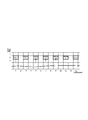
- FIG. 9 is an explanatory diagram for explaining emergency information.
- FIG. 10 is a flowchart for explaining the operation of the UE 100 according to the first embodiment.
- FIG. 11 is a flowchart for explaining the operation of the UE 100 according to the first embodiment.
- Urgent content is, for example, content related to attention, content related to a request for assistance, or content related to evacuation.
- the contents related to attention are attention contents, attention area information, and the like.
- the content related to the request for assistance includes location information of the user (UE) requesting assistance.
- the contents related to the evacuation are the evacuation route and the like.
- UE100 determines with transmitting emergency content by D2D communication, for example, when D2D communication data is designated by the user as emergency content.
- Emergency information is notification information indicating that there is D2D communication data scheduled to be transmitted, and in the present embodiment, the content of D2D communication data scheduled to be transmitted is emergency content.
- the emergency information may include information indicating the emergency level of the D2D communication data scheduled to be transmitted. For example, as shown in FIG. 9, the urgency level of the content related to attention is “1”, the urgency level of the content related to the request for assistance is “2”, and the urgency level of the content related to evacuation is “3”.
- the normal urgency may be set to “0”.
- Emergency resource is a dedicated time / frequency resource for transmitting emergency information. Emergency resources are periodically provided in the time axis direction. For example, the emergency resource may be provided with a cycle longer than that of the SA resource region, and specifically, may be provided with a cycle of 1024 [subframe].
- the other UEs 100 always search for emergency resources, and recognize emergency status when receiving emergency information transmitted using emergency resources.
- emergency information may collide.
- Other UE100 recognizes that it is in an emergency state, when it is a case where the content of emergency information cannot be read, when it detects that emergency information collided.
- the other UEs 100 detect the received power by searching (monitoring) emergency resources, and recognize the emergency state when the contents of the emergency information cannot be read.
- the UE 100 In the emergency state, the UE 100 is prohibited from transmitting D2D communication data other than emergency contents. Thereby, after transmitting emergency information, the UE 100 preferentially transmits an SA indicating the position of the data resource used for transmitting the emergency content D2D communication data using the SA resource. After that, the UE 100 transmits D2D communication data with urgent contents using the data resource indicated by the SA.
- the UE 100 may monitor the SA resource and the data resource immediately after transmitting the emergency information, and may transmit the SA after confirming the usage status of the SA resource and the data resource.
- the UE 100 determines the SA resource based on the SA resource information or the setting information.
- the emergency state is valid for a certain period, for example, the emergency state is valid for one cycle of the emergency resource.
- UE100 which transmitted emergency information may terminate an emergency state by transmitting the information which shows normal emergency degree using SA resource or a data resource.
- the other UE 100 monitors the SA resource area and receives the D2D communication data of the emergency content.
- UE100 can grasp
- the emergency information including the information indicating the emergency level and the SA and / or D2D communication data are associated with each other by the UE identifier or the like, the D2D communication data emergency level can be grasped.
- the UE 100 may preferentially display D2D communication data with a high degree of urgency on the user interface.
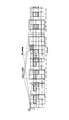
- the UE 100-1 periodically transmits SA (SA11, SA12) and D2D communication data (DATA11 to DATA13). Further, the UE 100-2 periodically transmits SA (SA21, SA22) and D2D communication data (DATA21 to DATA23). Each of UE 100-1 and UE 100-2 transmits D2D communication data up to a period to which n + 9 [subframe] belongs.
- Each of the UE 100-1 and the UE 100-2 plans to transmit D2D communication data in the next cycle, and determines the SA resource and the data resource as in the previous cycle.
- the UE 100-3 schedules transmission of D2D communication data with urgent contents, and transmits emergency information by broadcast using emergency resources. Specifically, the UE 100 transmits emergency information (Emergency) using the emergency resource at the position of (subframe (n + 10), RB1).
- Each of the UE 100-1 and the UE 100-2 monitors emergency resources and receives emergency information. Each of the UE 100-1 and the UE 100-2 that has received the emergency information recognizes that it is in an emergency state. Each of the UE 100-1 and the UE 100-2 stops the D2D communication scheduled to be transmitted because the D2D communication data scheduled to be transmitted is not urgent content. Specifically, each of UE 100-1 and UE 100-2 cancels the SA transmission that was scheduled for transmission. Thereby, SA is not transmitted in the SA resource area of n + 11, n + 12 [subframe]. Also, each of UE 100-1 and UE 100-2 cancels transmission of D2D communication data because SA indicating the position of the data resource is not transmitted.
- the SA resource in the SA resource area in the cycle immediately after the emergency information is transmitted is used.
- the SA indicating the position of the urgent D2D communication data is transmitted.
- the UE 100-3 monitors the SA resource area and the area (n + 11 to n + 20 [subframe]) where the D2D communication data is arranged. As a result of the monitoring, the UE 100-3 determines that the other UE 100 does not transmit the D2D communication data, and uses the SA resource in the SA resource area to change the SA 41 indicating the D2D communication data (DATA 41 or the like) that is emergency content. Send. Then, UE10 transmits DATA41 etc. using the data resource shown by SA.
- the UE 100-3 transmits SA using the SA resource in the SA resource area immediately after the other UE 100 transmits the emergency information
- the SA resource is determined based on the SA resource information or the setting information so that there is no collision.
- the UE 100-3 determines the position of the SA of the next period of the other UE 100. And SA resources are determined.
- each of the UE 100-1 and the UE 100-2 resumes the D2D communication after being out of the emergency state. Specifically, each of the UE 100-1 and the UE 100-2 monitors the emergency resource, and when the emergency information is not received, determines the SA resource and the data resource, and transmits the SA and D2D communication data. Resume.
- step S101 the UE 100 determines whether or not there is D2D communication data (emergency D2D data) with urgent contents in the D2D communication data scheduled to be transmitted.
- UE100 performs the process of step S102, when there exists emergency D2D data.
- UE100 complete finishes a process, when there is no emergency D2D data.
- step S102 the UE 100 broadcasts emergency information using the emergency resource. Further, the UE 100 determines a data resource used for transmission of emergency D2D data and a position of an SA resource indicating the position of the data resource.
- step S103 the UE 100 transmits the SA using the determined SA resource.
- step S104 emergency D2D data is transmitted using the data resource indicated by the determined SA.
- step S201 the UE 100 monitors emergency resources. If the UE 100 receives emergency information as a result of monitoring, the UE 100 executes the process of step S202. On the other hand, UE100 complete
- step S202 the UE 100 determines whether or not the D2D communication data scheduled to be transmitted held by the UE 100 itself is emergency D2D data. UE100 performs the process of step S203, when transmitting emergency D2D data. On the other hand, UE100 performs the process of step S204, when normal D2D communication data are due to be transmitted.
- step S204 may be executed without executing the process of step S203.
- step S203 the UE 100 transmits emergency D2D data and continues to transmit D2D communication data.
- the UE 100 stops the transmission of the D2D data until the emergency state disappears.
- step S204 the UE 100 stops (stops) transmission of SA and D2D communication data.
- UE100 is transmitting emergency D2D data, when emergency D2D data with higher urgency than the emergency D2D data hold
- the UE 100 after transmitting the emergency information, preferentially transmits an SA indicating the position of the data resource used for transmitting the emergency content D2D communication data. Thereby, it can reduce that SA of UE100 holding D2D communication data with high priority collides with SA of other UE100.
- the other UE 100 when the other UE 100 receives emergency information from the UE 100, the other UE 100 cancels transmission of the SA. Thereby, it can reduce that SA of UE100 holding D2D communication data with high priority collides with SA of other UE100.
- the other UE 100 when the content of the D2D communication data scheduled to be transmitted held by the other UE 100 is urgent content, the other UE 100 transmits the SA without canceling the SA transmission. Thereby, other UE100 can also transmit emergency D2D data preferentially.
- the other UE 100 cancels the transmission of the SA when the urgency level of the emergency D2D data held by the other UE 100 is lower than the urgency level indicated by the information included in the emergency information. Thereby, it is possible to reduce the collision between the SA having a higher priority and another SA having a lower priority.
- the other UE 100 resumes the transmission of the SA when the emergency information is not received by the emergency resource in the next cycle.
- the other SAs can grasp that the normal state has been reached, and can transmit SAs without collision with SAs with high urgency.
- the other UE 100 preferentially displays emergency D2D data having a high degree of urgency on the user interface. Thereby, the user can grasp
- the notification information is emergency information.
- the notification information is an SA transmission request for requesting to become a transmission UE of the next SA.
- FIG. 12 is a sequence for explaining the operation of the mobile communication system according to the second embodiment.
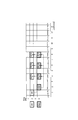
- FIG. 13 is a configuration diagram of a radio frame for explaining the mobile communication system according to the second embodiment.
- the UE 100 that transmits an SA determines the UE 100 that transmits the next SA.
- step S301 the UE 100-1 transmits SA11 indicating the positions of the data resources DATA11, DATA12, and DATA13 which are D2D communication data.
- SA11 indicating the positions of the data resources DATA11, DATA12, and DATA13 which are D2D communication data.
- UE 100-2 and UE 100-3 receives SA11.
- each of the UE 100-2 and the UE 100-3 transmits an SA transmission request (Order 11) using the SA transmission request resource.
- the SA transmission request indicates that there is D2D communication data scheduled to be transmitted, and requests to be selected as a transmission UE that transmits the SA after the UE 100-1.
- the SA transmission request resource which is a time / frequency resource for SA transmission request, is a dedicated time / frequency resource.
- the SA transmission request resource may be a predefined time / frequency resource, or may be specified by the UE 100-1 that transmits the SA. In this case, the UE 100-1 specifies a position different from the data resource as the position of the SA transmission request resource. Information specifying the position of the SA transmission request resource may be transmitted together with the SA 11 using the SA resource.
- Each of UE 100-2 and UE 100-3 may transmit an SA transmission request using a signal sequence (code code) unique to UE in order to distinguish it from other SA transmission requests.
- code code code code
- the UE 100-1 transmits the SA transmission request of each of the UE 100-2 and the UE 100-3.
- the UE 100-2 transmits an SA transmission request using code2
- the UE 100-3 transmits an SA transmission request using code3.
- the UE 100-1 receives the SA transmission request by scanning the SA transmission request resource. Thereby, the UE 100-1 grasps that the UE 100-2 and the UE 100-3 are requesting to transmit SA. Next, based on the SA transmission request, the UE 100-1 selects a transmission UE that transmits the SA next.
- the UE 100-1 may randomly select from the UEs that transmitted the SA transmission request, or may preferentially select a UE with a low transmission frequency. In the following, it is recommended that the UE 100-1 selects the UE 100-3.
- step S303 the UE 100-1 transmits each of DATA11 to DATA13 using the data resource indicated by SA11.
- Each of the UE 100-2 and the UE 100-3 receives DATA11 to DATA13.
- step S304 the UE 100-1 broadcasts an SA transmission notification (Decade 11) for notifying the selected transmission UE using the SA transmission notification resource. Specifically, the UE 100-1 transmits the SA transmission notification using the same signal sequence (code 3) as that of the selected UE 100-3 as the SA transmission request.
- the SA transmission notification resource which is a time / frequency resource for SA transmission notification, is a dedicated time / frequency resource.
- the SA transmission notification resource may be a predefined time / frequency resource, or may be specified by the UE 100-1 that transmits the SA. In this case, the UE 100-1 specifies a position different from the data resource as the position of the SA transmission request resource. Information specifying the position of the SA transmission notification resource may be transmitted together with the SA 11 using the SA resource.
- the UE 100-3 scans the SA transmission notification resource, thereby receiving the SA transmission notification transmitted using the same signal sequence (code 3) as the SA transmission request of the UE 100-3. As a result, the UE 100-3 recognizes that the UE 100-3 itself is the next transmitting UE that transmits the SA. The UE 100-3 determines an SA resource and a data resource in order to transmit D2D communication data.
- the UE 100-2 receives the SA transmission notification by scanning the SA transmission notification resource. As a result, the UE 100-2 recognizes that the UE 100-2 has not been selected as the next transmission UE for transmitting the SA.
- the UE 100-3 performs the same operation as the UE 100-1 in steps S301 and S303. Further, each of the UE 100-1 and the UE 100-2 performs the same operation as the UE 100-2 (or the UE 100-3) in Step S302.
- UE100 which transmits SA may select UE100 itself as transmission UE which transmits SA, when SA transmission request
- each of the UE 100-2 and the UE 100-3 transmits an SA transmission request.
- the UE 100-3 preferentially transmits the SA after transmitting the SA transmission request. This can reduce the collision of the SA of the UE 100-3 with the SA transmitted from the UE 100-1 and the UE 100-2.
- the UE 100-1 that transmits the SA selects the transmission UE that transmits the SA next based on the SA transmission request.
- the UE 100-3 transmits SA only when the UE 100-3 is selected as the transmission UE. This can reduce the collision of the SA of the UE 100-3 with the SA transmitted from the UE 100-1 and the UE 100-2.
- each of the UE 100-2 and the UE 100-3 transmits an SA transmission request using the SA transmission request resource.
- the UE 100-1 receives the SA transmission request by scanning the SA transmission request resource. Thereby, it is possible to avoid the SA transmission request from colliding with other radio signals.
- the UE 100-1 transmits information specifying the SA transmission request resource together with the SA.
- each of the UE 100-2 and the UE 100-3 can know the SA transmission request resource by performing a search of the SA resource area.
- the UE 100-1 transmits an SA transmission notification using the SA transmission notification resource.
- Each of the UE 100-2 and the UE 100-3 receives the SA transmission notification by scanning the SA transmission notification resource. Thereby, it is possible to avoid the SA transmission notification from colliding with other radio signals.
- the UE 100-1 transmits information specifying the SA transmission notification resource together with the SA.
- each of the UE 100-2 and the UE 100-3 can know the position of the SA notification request resource by performing a search of the SA resource area.
- the second embodiment described above may be applied to a D2D group configured by a plurality of UEs 100.
- Each of the plurality of D2D groups may apply the second embodiment described above when performing D2D communication using SA resources different from those of other D2D groups.
- the present invention is not limited to the LTE system, and the present invention may be applied to a system other than the LTE system.
- FIG. 14 shows a method in which UE2 detects SA1 transmitted by UE1 and schedules its own data transmission by avoiding resources listed in SA1 using this detection information. Furthermore, to improve the resource allocation, an additional operation for SA based on the resource allocation scheme is proposed.
- SA transmissions are periodic and uses a pre-defined time-frequency resource known to the receiver. .
- the locations for SA transmission resources can be grouped together in a region for simpler detection.
- Proposal 1 If SAs are agreed, SAs should be sent periodically and grouped together within a given region.
- Each SA is mapped to a specific set of time / frequency resources available for data transmission.
- Each D2D is allowed to select a resource for SA transmission as described in the section above. However, only the same D2D UE can transmit data in the resource associated with the SA resource location. That is, the position of the SA determines the position of the data transmission resource. As shown in FIG. 16, SA1 indicates data 11, 12, and 13, and SA2 indicates data 21, 22, and 23. This method can avoid a collision between data transmissions.
- Proposal 2 To avoid data collisions, the SA is mapped to a specific set of time and frequency resources available for data transmission.
- Each D2D UE monitors the SA area to detect SAs transmitted by other D2D UEs. With this monitoring information, the same D2D UE avoids transmitting SA using the same resource while other D2D UEs are transmitting SA earlier. For example, as shown in FIG. 17, UE1 and UE2 transmit SA11 and SA21, respectively. A third D2D UE (not shown) detects their transmission and transmits SA32 at another location. UE1 and UE2 can use the same resources used repeatedly for SA12 and SA22, respectively. In the first first SA period, UE1 and UE2 can randomly select resources for SA transmission.
- ⁇ Proposal 3 If the SA is agreed, in order to reduce SA collisions, the D2D UE avoids sending SAs on the same resources used by other D2D UEs in previous SA transmissions.
- the mobile communication system and the user terminal according to the present embodiment can reduce the collision of control information, they are useful in the mobile communication field.
Landscapes
- Engineering & Computer Science (AREA)
- Computer Networks & Wireless Communication (AREA)
- Signal Processing (AREA)
- Business, Economics & Management (AREA)
- Health & Medical Sciences (AREA)
- Emergency Management (AREA)
- Environmental & Geological Engineering (AREA)
- Public Health (AREA)
- Databases & Information Systems (AREA)
- Mobile Radio Communication Systems (AREA)
Abstract
Priority Applications (3)
| Application Number | Priority Date | Filing Date | Title |
|---|---|---|---|
| EP15743781.5A EP3101968A4 (fr) | 2014-01-31 | 2015-01-29 | Système de communication mobile et terminal d'utilisateur |
| JP2015559993A JP6446375B2 (ja) | 2014-01-31 | 2015-01-29 | 移動通信システム及びユーザ端末 |
| US15/220,434 US10070420B2 (en) | 2014-01-31 | 2016-07-27 | Mobile communication system and user terminal |
Applications Claiming Priority (2)
| Application Number | Priority Date | Filing Date | Title |
|---|---|---|---|
| US201461934323P | 2014-01-31 | 2014-01-31 | |
| US61/934,323 | 2014-01-31 |
Related Child Applications (1)
| Application Number | Title | Priority Date | Filing Date |
|---|---|---|---|
| US15/220,434 Continuation US10070420B2 (en) | 2014-01-31 | 2016-07-27 | Mobile communication system and user terminal |
Publications (1)
| Publication Number | Publication Date |
|---|---|
| WO2015115508A1 true WO2015115508A1 (fr) | 2015-08-06 |
Family
ID=53757080
Family Applications (1)
| Application Number | Title | Priority Date | Filing Date |
|---|---|---|---|
| PCT/JP2015/052418 Ceased WO2015115508A1 (fr) | 2014-01-31 | 2015-01-29 | Système de communication mobile et terminal d'utilisateur |
Country Status (4)
| Country | Link |
|---|---|
| US (1) | US10070420B2 (fr) |
| EP (1) | EP3101968A4 (fr) |
| JP (1) | JP6446375B2 (fr) |
| WO (1) | WO2015115508A1 (fr) |
Cited By (5)
| Publication number | Priority date | Publication date | Assignee | Title |
|---|---|---|---|---|
| WO2016136492A1 (fr) * | 2015-02-27 | 2016-09-01 | 京セラ株式会社 | Terminal sans fil et station de base |
| WO2017133432A1 (fr) * | 2016-02-04 | 2017-08-10 | Jrd Communication Inc. | Commande de transmission de données directe entre des dispositifs mobiles dans un réseau sans fil |
| CN107079480A (zh) * | 2015-09-18 | 2017-08-18 | 华为技术有限公司 | 一种控制信息的传输方法、发送端和接收端 |
| JPWO2020054079A1 (ja) * | 2018-09-14 | 2021-09-24 | 富士通株式会社 | 無線端末、無線通信システム、及び無線基地局 |
| JPWO2024053054A1 (fr) * | 2022-09-08 | 2024-03-14 |
Families Citing this family (2)
| Publication number | Priority date | Publication date | Assignee | Title |
|---|---|---|---|---|
| JP6446375B2 (ja) * | 2014-01-31 | 2018-12-26 | 京セラ株式会社 | 移動通信システム及びユーザ端末 |
| WO2016089185A1 (fr) * | 2014-12-05 | 2016-06-09 | 엘지전자 주식회사 | Procédé et appareil permettant à un terminal de transmettre et de recevoir un signal à l'aide de liaisons auxiliaires entre des dispositifs |
Citations (1)
| Publication number | Priority date | Publication date | Assignee | Title |
|---|---|---|---|---|
| WO2012059793A1 (fr) * | 2010-11-05 | 2012-05-10 | Nokia Corporation | Procédé et appareil de planification de ressources de fréquence radio dans un contexte de piles radio multiples |
Family Cites Families (9)
| Publication number | Priority date | Publication date | Assignee | Title |
|---|---|---|---|---|
| US9706340B2 (en) * | 2012-02-16 | 2017-07-11 | Lg Electronics Inc. | Method and apparatus performing proximity service in wireless communication system |
| US9883496B2 (en) | 2012-03-06 | 2018-01-30 | Lg Electronics Inc. | Method and apparatus for transmitting/receiving control information for device to device (D2D) communication in a wireless communications system |
| US20150045078A1 (en) * | 2012-04-09 | 2015-02-12 | Lg Electronics Inc. | Method for d2d terminal transmitting and receiving data in wireless communication system supporting device-to-device communication |
| JP6209595B2 (ja) * | 2012-05-11 | 2017-10-04 | インターデイジタル パテント ホールディングス インコーポレイテッド | コンテキストアウェアピアツーピア通信 |
| EP2853132A1 (fr) * | 2012-05-23 | 2015-04-01 | Kyocera Corporation | Transmission de données de commande de dispositif à dispositif (d2d) d'un premier dispositif d2d à un second dispositif d2d dans un système de communication cellulaire |
| US9516653B2 (en) * | 2012-06-22 | 2016-12-06 | Lg Electronics Inc. | Scheduling method for device-to-device communication and apparatus for same |
| US9112685B2 (en) * | 2013-05-10 | 2015-08-18 | Blackberry Limited | Mechanisms for direct inter-device signaling |
| WO2015113589A1 (fr) * | 2014-01-28 | 2015-08-06 | Nokia Solutions And Networks Oy | Contrôle d'occupation de canal semi-persistent pour des communications sans fil de dispositif à dispositif (d2d) |
| JP6446375B2 (ja) * | 2014-01-31 | 2018-12-26 | 京セラ株式会社 | 移動通信システム及びユーザ端末 |
-
2015
- 2015-01-29 JP JP2015559993A patent/JP6446375B2/ja active Active
- 2015-01-29 EP EP15743781.5A patent/EP3101968A4/fr not_active Withdrawn
- 2015-01-29 WO PCT/JP2015/052418 patent/WO2015115508A1/fr not_active Ceased
-
2016
- 2016-07-27 US US15/220,434 patent/US10070420B2/en active Active
Patent Citations (1)
| Publication number | Priority date | Publication date | Assignee | Title |
|---|---|---|---|---|
| WO2012059793A1 (fr) * | 2010-11-05 | 2012-05-10 | Nokia Corporation | Procédé et appareil de planification de ressources de fréquence radio dans un contexte de piles radio multiples |
Non-Patent Citations (4)
| Title |
|---|
| "TR 36.843 VI.0.0", 3GPP TECHNICAL REPORT, 16 January 2014 (2014-01-16) |
| ERICSSON: "On D2D broadcast communication procedures", 3GPP TSG-RAN WG1 MEETING #74BIS RL-134704, 28 September 2013 (2013-09-28), pages 1 - 3, XP050717767 * |
| ETRI: "Unicast, groupcast/broadcast, and relay for public safety D2D communications", 3GPP TSG-RAN1 MEETING #74 RL-133181, pages 1 - 11, XP050716390 * |
| See also references of EP3101968A4 |
Cited By (11)
| Publication number | Priority date | Publication date | Assignee | Title |
|---|---|---|---|---|
| WO2016136492A1 (fr) * | 2015-02-27 | 2016-09-01 | 京セラ株式会社 | Terminal sans fil et station de base |
| CN107079480A (zh) * | 2015-09-18 | 2017-08-18 | 华为技术有限公司 | 一种控制信息的传输方法、发送端和接收端 |
| KR20180044349A (ko) * | 2015-09-18 | 2018-05-02 | 후아웨이 테크놀러지 컴퍼니 리미티드 | 제어 정보 송신 방법, 송신단 및 수신단 |
| JP2018526926A (ja) * | 2015-09-18 | 2018-09-13 | 華為技術有限公司Huawei Technologies Co.,Ltd. | 制御情報伝送方法、送信端、および受信端 |
| KR102126400B1 (ko) * | 2015-09-18 | 2020-06-24 | 후아웨이 테크놀러지 컴퍼니 리미티드 | 제어 정보 송신 방법, 송신단 및 수신단 |
| US11357032B2 (en) | 2015-09-18 | 2022-06-07 | Huawei Technologies Co., Ltd. | Control information transmission method, transmit end, and receive end |
| WO2017133432A1 (fr) * | 2016-02-04 | 2017-08-10 | Jrd Communication Inc. | Commande de transmission de données directe entre des dispositifs mobiles dans un réseau sans fil |
| JPWO2020054079A1 (ja) * | 2018-09-14 | 2021-09-24 | 富士通株式会社 | 無線端末、無線通信システム、及び無線基地局 |
| JP7140198B2 (ja) | 2018-09-14 | 2022-09-21 | 富士通株式会社 | 無線端末、無線通信システム、及び無線基地局 |
| JPWO2024053054A1 (fr) * | 2022-09-08 | 2024-03-14 | ||
| WO2024053054A1 (fr) * | 2022-09-08 | 2024-03-14 | 本田技研工業株式会社 | Dispositif terminal et procédé de commande de communication |
Also Published As
| Publication number | Publication date |
|---|---|
| JPWO2015115508A1 (ja) | 2017-03-23 |
| US10070420B2 (en) | 2018-09-04 |
| US20160338016A1 (en) | 2016-11-17 |
| EP3101968A1 (fr) | 2016-12-07 |
| EP3101968A4 (fr) | 2017-10-04 |
| JP6446375B2 (ja) | 2018-12-26 |
Similar Documents
| Publication | Publication Date | Title |
|---|---|---|
| JP6621551B2 (ja) | 通信方法、ユーザ装置、プロセッサ及び通信システム | |
| JP6799600B2 (ja) | 通信装置及びプロセッサ | |
| JP6026549B2 (ja) | 移動通信システム、基地局及びユーザ端末 | |
| JP6446375B2 (ja) | 移動通信システム及びユーザ端末 | |
| JP6313485B2 (ja) | ユーザ端末、移動通信方法及びプロセッサ | |
| US11368836B2 (en) | Communication method, radio terminal, processor, and base station | |
| WO2014129452A1 (fr) | Système de communication mobile, terminal utilisateur et station de base | |
| JP2018152888A (ja) | 通信制御方法、ユーザ端末及びプロセッサ | |
| EP3051852A1 (fr) | Terminal utilisateur, dispositif de réseau et processeur | |
| WO2015029952A1 (fr) | Dispositif utilisateur et terminal utilisateur | |
| WO2015083686A1 (fr) | Procédé de commande de communication, terminal d'utilisateur, et station de base | |
| JP6106286B2 (ja) | ユーザ端末及びプロセッサ | |
| WO2016163474A1 (fr) | Terminal utilisateur |
Legal Events
| Date | Code | Title | Description |
|---|---|---|---|
| 121 | Ep: the epo has been informed by wipo that ep was designated in this application |
Ref document number: 15743781 Country of ref document: EP Kind code of ref document: A1 |
|
| ENP | Entry into the national phase |
Ref document number: 2015559993 Country of ref document: JP Kind code of ref document: A |
|
| REEP | Request for entry into the european phase |
Ref document number: 2015743781 Country of ref document: EP |
|
| WWE | Wipo information: entry into national phase |
Ref document number: 2015743781 Country of ref document: EP |
|
| NENP | Non-entry into the national phase |
Ref country code: DE |