WO2015119081A1 - 廃熱回収システム - Google Patents
廃熱回収システム Download PDFInfo
- Publication number
- WO2015119081A1 WO2015119081A1 PCT/JP2015/052869 JP2015052869W WO2015119081A1 WO 2015119081 A1 WO2015119081 A1 WO 2015119081A1 JP 2015052869 W JP2015052869 W JP 2015052869W WO 2015119081 A1 WO2015119081 A1 WO 2015119081A1
- Authority
- WO
- WIPO (PCT)
- Prior art keywords
- refrigerant
- expander
- waste heat
- temperature
- condenser
- Prior art date
- Legal status (The legal status is an assumption and is not a legal conclusion. Google has not performed a legal analysis and makes no representation as to the accuracy of the status listed.)
- Ceased
Links
Images

Classifications
-
- F—MECHANICAL ENGINEERING; LIGHTING; HEATING; WEAPONS; BLASTING
- F01—MACHINES OR ENGINES IN GENERAL; ENGINE PLANTS IN GENERAL; STEAM ENGINES
- F01K—STEAM ENGINE PLANTS; STEAM ACCUMULATORS; ENGINE PLANTS NOT OTHERWISE PROVIDED FOR; ENGINES USING SPECIAL WORKING FLUIDS OR CYCLES
- F01K7/00—Steam engine plants characterised by the use of specific types of engine; Plants or engines characterised by their use of special steam systems, cycles or processes; Control means specially adapted for such systems, cycles or processes; Use of withdrawn or exhaust steam for feed-water heating
- F01K7/16—Steam engine plants characterised by the use of specific types of engine; Plants or engines characterised by their use of special steam systems, cycles or processes; Control means specially adapted for such systems, cycles or processes; Use of withdrawn or exhaust steam for feed-water heating the engines being only of turbine type
-
- F—MECHANICAL ENGINEERING; LIGHTING; HEATING; WEAPONS; BLASTING
- F01—MACHINES OR ENGINES IN GENERAL; ENGINE PLANTS IN GENERAL; STEAM ENGINES
- F01K—STEAM ENGINE PLANTS; STEAM ACCUMULATORS; ENGINE PLANTS NOT OTHERWISE PROVIDED FOR; ENGINES USING SPECIAL WORKING FLUIDS OR CYCLES
- F01K13/00—General layout or general methods of operation of complete plants
- F01K13/02—Controlling, e.g. stopping or starting
-
- F—MECHANICAL ENGINEERING; LIGHTING; HEATING; WEAPONS; BLASTING
- F01—MACHINES OR ENGINES IN GENERAL; ENGINE PLANTS IN GENERAL; STEAM ENGINES
- F01K—STEAM ENGINE PLANTS; STEAM ACCUMULATORS; ENGINE PLANTS NOT OTHERWISE PROVIDED FOR; ENGINES USING SPECIAL WORKING FLUIDS OR CYCLES
- F01K23/00—Plants characterised by more than one engine delivering power external to the plant, the engines being driven by different fluids
- F01K23/02—Plants characterised by more than one engine delivering power external to the plant, the engines being driven by different fluids the engine cycles being thermally coupled
- F01K23/06—Plants characterised by more than one engine delivering power external to the plant, the engines being driven by different fluids the engine cycles being thermally coupled combustion heat from one cycle heating the fluid in another cycle
- F01K23/065—Plants characterised by more than one engine delivering power external to the plant, the engines being driven by different fluids the engine cycles being thermally coupled combustion heat from one cycle heating the fluid in another cycle the combustion taking place in an internal combustion piston engine, e.g. a diesel engine
-
- F—MECHANICAL ENGINEERING; LIGHTING; HEATING; WEAPONS; BLASTING
- F01—MACHINES OR ENGINES IN GENERAL; ENGINE PLANTS IN GENERAL; STEAM ENGINES
- F01K—STEAM ENGINE PLANTS; STEAM ACCUMULATORS; ENGINE PLANTS NOT OTHERWISE PROVIDED FOR; ENGINES USING SPECIAL WORKING FLUIDS OR CYCLES
- F01K25/00—Plants or engines characterised by use of special working fluids, not otherwise provided for; Plants operating in closed cycles and not otherwise provided for
- F01K25/08—Plants or engines characterised by use of special working fluids, not otherwise provided for; Plants operating in closed cycles and not otherwise provided for using special vapours
-
- F—MECHANICAL ENGINEERING; LIGHTING; HEATING; WEAPONS; BLASTING
- F01—MACHINES OR ENGINES IN GENERAL; ENGINE PLANTS IN GENERAL; STEAM ENGINES
- F01K—STEAM ENGINE PLANTS; STEAM ACCUMULATORS; ENGINE PLANTS NOT OTHERWISE PROVIDED FOR; ENGINES USING SPECIAL WORKING FLUIDS OR CYCLES
- F01K5/00—Plants characterised by use of means for storing steam in an alkali to increase steam pressure, e.g. of Honigmann or Koenemann type
- F01K5/02—Plants characterised by use of means for storing steam in an alkali to increase steam pressure, e.g. of Honigmann or Koenemann type used in regenerative installation
-
- F—MECHANICAL ENGINEERING; LIGHTING; HEATING; WEAPONS; BLASTING
- F02—COMBUSTION ENGINES; HOT-GAS OR COMBUSTION-PRODUCT ENGINE PLANTS
- F02G—HOT GAS OR COMBUSTION-PRODUCT POSITIVE-DISPLACEMENT ENGINE PLANTS; USE OF WASTE HEAT OF COMBUSTION ENGINES; NOT OTHERWISE PROVIDED FOR
- F02G5/00—Profiting from waste heat of combustion engines, not otherwise provided for
- F02G5/02—Profiting from waste heat of exhaust gases
-
- Y—GENERAL TAGGING OF NEW TECHNOLOGICAL DEVELOPMENTS; GENERAL TAGGING OF CROSS-SECTIONAL TECHNOLOGIES SPANNING OVER SEVERAL SECTIONS OF THE IPC; TECHNICAL SUBJECTS COVERED BY FORMER USPC CROSS-REFERENCE ART COLLECTIONS [XRACs] AND DIGESTS
- Y02—TECHNOLOGIES OR APPLICATIONS FOR MITIGATION OR ADAPTATION AGAINST CLIMATE CHANGE
- Y02T—CLIMATE CHANGE MITIGATION TECHNOLOGIES RELATED TO TRANSPORTATION
- Y02T10/00—Road transport of goods or passengers
- Y02T10/10—Internal combustion engine [ICE] based vehicles
- Y02T10/12—Improving ICE efficiencies
Definitions
- the present invention relates to a waste heat recovery system, and more particularly to a waste heat recovery system that recovers waste heat of an internal combustion engine with high efficiency without causing thermal decomposition of a refrigerant in a Rankine cycle.
- the Rankine cycle is used as described in Japanese Patent Application Laid-Open No. 11-51582 (Patent Document 1) for the purpose of recovering waste heat of an internal combustion engine and improving fuel consumption.
- Patent Document 1 Japanese Patent Application Laid-Open No. 11-51582
- the fluorocarbon refrigerant used in the Rankine cycle for waste heat recovery is vaporized at a low temperature, it has a feature that the Rankine cycle can be operated even at a low temperature heat source of 100 ° C. or lower by setting an appropriate pressure.
- the temperature of the refrigerant cannot be higher than the thermal decomposition temperature.
- An object of the present invention is to provide a waste heat recovery system capable of recovering waste heat of an internal combustion engine with high efficiency without causing thermal decomposition of a refrigerant in a Rankine cycle.
- the waste heat recovery system of the present invention that achieves the above object includes a Rankine cycle in which a refrigerant is circulated in order through a refrigerant pump, an evaporator, an expander, and a condenser, and a control means that controls the Rankine cycle.
- a Rankine cycle in which a refrigerant is circulated in order through a refrigerant pump, an evaporator, an expander, and a condenser, and a control means that controls the Rankine cycle.
- at least one other set of another expander and condenser is arranged in parallel with the set of the expander and condenser.
- the expansion unit in another set connected in parallel is provided with an operation stop means for stopping the operation, and a pressure sensor and a temperature sensor are respectively provided at the inlet and the outlet of the evaporator, and the control Means is a small amount of the operation stop means so that the measured value of the temperature sensor is equal to or lower than the thermal decomposition temperature of the refrigerant and becomes a preset specified temperature value.
- sets or releases the Kutomo one is characterized in controlling the rotational speed of the coolant pump so that the measured value of the pressure sensor becomes a preset prescribed pressure value.
- a plurality of expanders and condensers in a conventional Rankine cycle are connected in parallel, and a flow path is appropriately selected according to the temperature of the refrigerant.
- the temperature of the refrigerant in the Rankine cycle is always kept at a temperature value under pressure that is lower than the thermal decomposition temperature and operates at high efficiency, so that the waste heat of the internal combustion engine is reduced in the Rankine cycle.
- the refrigerant can be recovered with high efficiency without causing thermal decomposition of the refrigerant.
- FIG. 1 is a configuration diagram of a waste heat recovery system according to an embodiment of the present invention.
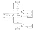
- FIG. 2 is a flowchart for explaining the control contents of the ECU in the waste heat recovery system according to the embodiment of the present invention.
- FIG. 1 shows a waste heat recovery system according to an embodiment of the present invention.
- the arrow in a figure has shown the direction through which the fluid flows.
- This waste heat recovery system is mounted on a vehicle such as a truck, and includes a Rankine cycle 6 in which a refrigerant 5 is circulated through a refrigerant pump 1, an evaporator 2, an expander 3, and a condenser 4 in order.
- the purpose is to recover the waste heat of a certain diesel engine 7.
- the refrigerant 5 flowing through the Rankine cycle 6 is compressed in a liquid state in the refrigerant pump 1, is heated at a constant pressure in the evaporator 2 to become high-pressure gas, and is adiabatically expanded in the expander 3, and a generator 9 through the turbine shaft 8. Is driven to rotate to generate electric power, and then cooled at a constant pressure in the condenser 4 to return to a liquid.
- n sets S (where n is a natural number) connected in parallel to the expander 3 and the condenser 4 in the Rankine cycle 6 are composed of another expander E and a condenser C having the same specifications as those. .
- the operation stop means B is not particularly limited, and examples thereof include a brake for applying a mechanical load to the turbine shaft A of the expander E. Incidentally, when the operation stop means B n is set, the refrigerant 5 is prevented from circulating in the set S n.
- a pressure sensor 10 that measures the pressure of the refrigerant 5 is disposed on the inlet side of the evaporator 2, and a temperature sensor 11 that measures the temperature of the refrigerant 5 is disposed on the outlet side.
- the operation stopping means B 1 to B n , the refrigerant pump 1, the pressure sensor 10 and the temperature sensor 11 are connected to the ECU 12 as control means through signal lines (indicated by a one-dot chain line).
- n of the set S is appropriately determined depending on the specifications and operating conditions of the diesel engine 7 and the performance of the refrigerant pump 1 and the evaporator 2.
- the ECU After initializing the control variable i (integer) (S10), the ECU inputs the measured value T of the temperature sensor 11 (S15), and the measured value T is equal to or lower than the thermal decomposition temperature of the refrigerant 5. At least one of the operation stop means B 1 to B n is set or canceled so as to be equal to the specified temperature value Ts.
- the specified temperature value Ts is a temperature at which the refrigerant 5 operates with high efficiency in the Rankine cycle 6, and is determined by the type of the refrigerant 5.
- the respective operation stopping means B 1 to B n are set in order. (S25 to S30) allows the refrigerant 5 to flow only through the conventional expander 3 and condenser 4 or in addition to an appropriate number of sets S.
- the measured value T exceeds the specified temperature value Ts (S35)
- the respective operation stop means B 1 to B n are sequentially released (S40).
- S45 the refrigerant 5 flows through an appropriate number of sets S in addition to the conventional expander 3 and condenser 4.
- the measured value T is equal to the specified temperature value Ts (S50)
- the measured value P of the pressure sensor 10 is input (S55), and the measured value P is equal to the preset specified pressure value Ps.
- the rotational speed of the refrigerant pump 1 is controlled (S60 to S65).
- the specified pressure value Ps is a pressure at which the refrigerant 5 operates with high efficiency in the Rankine cycle 6, and is determined by the type of the refrigerant 5.
- the temperature of the refrigerant 5 of the Rankine cycle 6 is always equal to or lower than the thermal decomposition temperature and a temperature value under pressure that operates with high efficiency.
- the waste heat of the diesel engine 7 can be recovered with high efficiency without thermally decomposing the refrigerant 5.
- the waste heat recovery system of the present invention can be mounted not only on a vehicle such as the truck described above but also on a fixed power generator or a large generator. Further, the internal combustion engine is not limited to the diesel engine 7.
Landscapes
- Engineering & Computer Science (AREA)
- Chemical & Material Sciences (AREA)
- Combustion & Propulsion (AREA)
- Mechanical Engineering (AREA)
- General Engineering & Computer Science (AREA)
- Engine Equipment That Uses Special Cycles (AREA)
- Power Engineering (AREA)
- Control Of Turbines (AREA)
Abstract
ランキンサイクル6の膨張器3及び凝縮器4に対して、別の膨張器E及び凝縮器CからなるセットSをn個並列に接続するとともに、それらの並列に接続されたセットS1~Snにおける膨張器E1~Enに作動を停止させる作動停止手段B1~Bnを設け、かつ蒸発器2の入口及び出口に圧力センサ10及び温度センサ11をそれぞれ配設する。ECU12は、温度センサ11の測定値Tが、冷媒5の熱分解温度以下であって予め設定された規定温度値Tsとなるように、作動停止手段B1~Bnのうちの少なくとも1つを設定又は解除するとともに、圧力センサ10の測定値Pが予め設定された規定圧力値Psになるように冷媒ポンプ1の回転数を制御する。
Description
本発明は廃熱回収システムに関し、更に詳しくは、内燃機関の廃熱をランキンサイクルにおける冷媒の熱分解を招くことなく高効率で回収する廃熱回収システムに関する。
従来より、内燃機関の廃熱を回収して燃費を向上させることを目的として、日本出願の特開平11-51582号公報(特許文献1)に記載されているように、ランキンサイクルを利用することが提案されている。このランキンサイクルを効率よく作動させるためには、冷媒の圧力を変化させることにより、その蒸発温度を調整する必要がある。廃熱回収用のランキンサイクルで使用されるフロン系の冷媒は、低温で気化するため、適切な圧力にすることで100℃以下の低温の熱源でもランキンサイクルを作動できるという特徴を有しているが、その冷媒の温度を熱分解温度よりも高温にすることができないという欠点がある。
自動車等の内燃機関から排ガスの廃熱を回収する際には、運転状況によっては排ガスの温度が100~800℃と大きく変化する。更に、排ガスの温度が高いときには、排気流量も比例して増加するため、廃熱量も非常に大きくなる。また、内燃機関の冷却水からの廃熱についても、温度は80~100℃と大きく変化しないが、廃熱量は大きく変化する。
上記のように熱量が大きく変化する廃熱を回収する場合において、ランキンサイクルの冷媒の温度を、熱分解温度以下であって、かつ高効率に作動する圧力下での蒸発温度に保つためには、冷媒の流量を適正に変化させればよい。
しかしながら、従来の廃熱回収用のランキンサイクルのように、膨張器及びポンプがそれぞれ1台ずつしかない構成では、圧力を既定値に保ちながら温度が一定に維持されるように冷媒の流量を変化させることは困難であった。
本発明の目的は、内燃機関の廃熱をランキンサイクルにおける冷媒の熱分解を招くことなく高効率で回収することができる廃熱回収システムを提供することにある。
上記の目的を達成する本発明の廃熱回収システムは、冷媒ポンプ、蒸発器、膨張器及び凝縮器を冷媒が順に循環してなるランキンサイクルと、前記ランキンサイクルを制御する制御手段とを備え、前記蒸発器の加熱源に内燃機関の廃熱を用いる廃熱回収システムにおいて、前記膨張器及び凝縮器からなるセットに対して、別の膨張器及び凝縮器からなる別のセットを少なくとも一個並列に接続するとともに、それら並列に接続された別のセットにおける膨張器にその作動を停止させる作動停止手段を設け、かつ前記蒸発器の入口及び出口に圧力センサ及び温度センサをそれぞれ配設し、前記制御手段は、前記温度センサの測定値が、前記冷媒の熱分解温度以下であって予め設定された規定温度値となるように、前記作動停止手段のうちの少なくとも1つを設定又は解除するとともに、前記圧力センサの測定値が予め設定された規定圧力値になるように前記冷媒ポンプの回転数を制御することを特徴とするものである。
本発明の廃熱回収システムによれば、従来のランキンサイクルにおける膨張器及び凝縮器を並列に複数接続して、冷媒の温度に応じて流路を適切に選択することで、内燃機関の廃熱量が変化しても、ランキンサイクルの冷媒の温度が、熱分解温度以下であって高効率に作動する圧力下の温度値に常に維持されるようにしたので、内燃機関の廃熱をランキンサイクルにおける冷媒の熱分解を招くことなく高効率で回収することができる。
以下に、本発明の実施の形態について、図面を参照して説明する。図1は、本発明の実施形態からなる廃熱回収システムを示す。なお、図中の矢印は流体の流れる方向を示している。
この廃熱回収システムは、トラックなどの車両に搭載され、冷媒ポンプ1、蒸発器2、膨張器3及び凝縮器4を冷媒5が順に循環してなるランキンサイクル6を備えており、内燃機関であるディーゼルエンジン7の廃熱を回収することを目的としている。
ランキンサイクル6における蒸発器2の加熱源には、ディーゼルエンジン7の排ガスや、エンジン本体用の冷却水などが用いられる。また、凝縮器4の冷却源には、インタークーラー用の冷却水などが用いられる。また、冷媒5としては、水、エタノール及びフッ素化合物などが例示される。
ランキンサイクル6を流れる冷媒5は、冷媒ポンプ1において液体の状態で圧縮され、蒸発器2において定圧的に加熱されて高圧のガスとなり、膨張器3で断熱膨張しつつタービン軸8を通じて発電機9を回転駆動して発電させた後に、凝縮器4において定圧的に冷却されて液体に戻る。
そして、このランキンサイクル6における膨張器3及び凝縮器4に対して、それらと同一仕様の別の膨張器E及び凝縮器CからなるセットSがn個(nは自然数)並列に接続されている。また、各セットS1~Snにおける膨張器E1~Enには、設定又は解除することにより膨張器E1~Enの作動を停止又は進行させる作動停止手段B1~Bnがそれぞれ取り付けられている。この作動停止手段Bとしては、特に限定するものではないが、膨張器Eのタービン軸Aに機械的な負荷を加えるブレーキなどが例示される。なお、作動停止手段Bnが設定されると、当該セットSnには冷媒5は循環しないようになる。
更に、蒸発器2の入口側には冷媒5の圧力を測定する圧力センサ10が、出口側には冷媒5の温度を測定する温度センサ11が、それぞれ配設されている。
上記の作動停止手段B1~Bn、冷媒ポンプ1、圧力センサ10及び温度センサ11は、制御手段であるECU12に信号線(一点鎖線で示す)を通じてそれぞれ接続している。
なお、上記のセットSの個数nは、ディーゼルエンジン7の仕様及び運転条件や、冷媒ポンプ1及び蒸発器2の性能により適宜決定される。
このような廃熱回収システムにおけるECU12の制御内容を、図2に基づいて以下に説明する。
ECUは、制御変数i(整数)を初期化した後に(S10)、温度センサ11の測定値Tを入力し(S15)、その測定値Tが冷媒5の熱分解温度以下であって予め設定された規定温度値Tsと等しくなるように各作動停止手段B1~Bnのうちの少なくとも1つを設定又は解除する。この規定温度値Tsは、ランキンサイクル6において冷媒5が高効率に作動する温度であり、冷媒5の種類により決定される。
具体的には、測定値Tが規定温度値Ts未満であるときは(S20)、ディーゼルエンジン7の廃熱量が比較的小さいと判断して、各作動停止手段B1~Bnを順に設定する(S25~S30)ことにより、従来の膨張器3及び凝縮器4にのみ、又はそれに加えて適切な個数のセットSにのみ冷媒5が流れるようにする。一方で、測定値Tが規定温度値Ts超であるときは(S35)、ディーゼルエンジン7の廃熱量が比較的大きいと判断して、各作動停止手段B1~Bnを順に解除する(S40~S45)ことにより、従来の膨張器3及び凝縮器4に加えて適切な個数のセットSに冷媒5が流れるようにする。
そして、測定値Tが規定温度値Tsと等しくなったと判断したときには(S50)、圧力センサ10の測定値Pを入力し(S55)、その測定値Pが予め設定された規定圧力値Psと等しくなるように冷媒ポンプ1の回転数を制御する(S60~S65)。この規定圧力値Psは、ランキンサイクル6において冷媒5が高効率に作動する圧力であり、冷媒5の種類により決定される。
ディーゼルエンジン7の運転時においては、上記のステップ10~65を繰り返す。
このような制御を行うことで、ディーゼルエンジン7の廃熱量が変化しても、ランキンサイクル6の冷媒5の温度が、熱分解温度以下であって高効率に作動する圧力下の温度値に常に維持されるので、ディーゼルエンジン7の廃熱を、冷媒5を熱分解させることなく高効率で回収することができるのである。
本発明の廃熱回収システムは、上述したトラックなどの車両に限らず、固定式の動力発生機や大型発電機などにも搭載することができる。また、内燃機関はディーゼルエンジン7に限るものではない。
1 冷媒ポンプ
2 蒸発器
3、E 膨張器
4、C 凝縮器
5 冷媒
6 ランキンサイクル
7 ディーゼルエンジン
10 圧力センサ
11 温度センサ
12 ECU
B 作動停止手段
S セット
2 蒸発器
3、E 膨張器
4、C 凝縮器
5 冷媒
6 ランキンサイクル
7 ディーゼルエンジン
10 圧力センサ
11 温度センサ
12 ECU
B 作動停止手段
S セット
Claims (2)
- 冷媒ポンプ、蒸発器、膨張器及び凝縮器を冷媒が順に循環してなるランキンサイクルと、前記ランキンサイクルを制御する制御手段とを備え、前記蒸発器の加熱源に内燃機関の廃熱を用いる廃熱回収システムにおいて、
前記膨張器及び凝縮器からなるセットに対して、別の膨張器及び凝縮器からなる別のセットを少なくとも一個並列に接続するとともに、それら並列に接続された別のセットにおける膨張器にその作動を停止させる作動停止手段を設け、かつ前記蒸発器の入口及び出口に圧力センサ及び温度センサをそれぞれ配設し、
前記制御手段は、前記温度センサの測定値が、前記冷媒の熱分解温度以下であって予め設定された規定温度値となるように、前記作動停止手段のうちの少なくとも1つを設定又は解除するとともに、前記圧力センサの測定値が予め設定された規定圧力値になるように前記冷媒ポンプの回転数を制御することを特徴とする廃熱回収システム。 - 前記作動停止手段が、前記別の膨張器の回転軸に負荷を加えるブレーキである請求項1に記載の廃熱回収システム。
Priority Applications (3)
| Application Number | Priority Date | Filing Date | Title |
|---|---|---|---|
| US15/031,065 US9819193B2 (en) | 2014-02-07 | 2015-02-02 | Waste heat recovery system |
| CN201580001993.7A CN105593476B (zh) | 2014-02-07 | 2015-02-02 | 废热回收系统 |
| EP15746099.9A EP3103975B1 (en) | 2014-02-07 | 2015-02-02 | Waste heat recovery system |
Applications Claiming Priority (2)
| Application Number | Priority Date | Filing Date | Title |
|---|---|---|---|
| JP2014-022158 | 2014-02-07 | ||
| JP2014022158A JP6217426B2 (ja) | 2014-02-07 | 2014-02-07 | 廃熱回収システム |
Publications (1)
| Publication Number | Publication Date |
|---|---|
| WO2015119081A1 true WO2015119081A1 (ja) | 2015-08-13 |
Family
ID=53777886
Family Applications (1)
| Application Number | Title | Priority Date | Filing Date |
|---|---|---|---|
| PCT/JP2015/052869 Ceased WO2015119081A1 (ja) | 2014-02-07 | 2015-02-02 | 廃熱回収システム |
Country Status (5)
| Country | Link |
|---|---|
| US (1) | US9819193B2 (ja) |
| EP (1) | EP3103975B1 (ja) |
| JP (1) | JP6217426B2 (ja) |
| CN (1) | CN105593476B (ja) |
| WO (1) | WO2015119081A1 (ja) |
Families Citing this family (2)
| Publication number | Priority date | Publication date | Assignee | Title |
|---|---|---|---|---|
| JP6757631B2 (ja) * | 2016-09-02 | 2020-09-23 | 株式会社Ihi回転機械エンジニアリング | バイナリー発電システム |
| CN110553240A (zh) * | 2018-06-01 | 2019-12-10 | 新疆北方建设集团有限公司 | 一种朗肯循环的装置及其方法 |
Citations (4)
| Publication number | Priority date | Publication date | Assignee | Title |
|---|---|---|---|---|
| JPS59185808A (ja) * | 1983-04-07 | 1984-10-22 | Toshiba Corp | 発電プラントの主蒸気圧制御装置 |
| JP2008175108A (ja) * | 2007-01-17 | 2008-07-31 | Yanmar Co Ltd | ランキンサイクル動力回収装置 |
| JP2010048129A (ja) * | 2008-08-20 | 2010-03-04 | Sanden Corp | 内燃機関の廃熱利用装置 |
| JP2013217221A (ja) * | 2012-04-05 | 2013-10-24 | Toyota Industries Corp | ランキンサイクル装置 |
Family Cites Families (44)
| Publication number | Priority date | Publication date | Assignee | Title |
|---|---|---|---|---|
| US4437316A (en) * | 1981-01-23 | 1984-03-20 | Technology Marketing Inc. | Method and apparatus for recovering waste energy |
| US20030213246A1 (en) * | 2002-05-15 | 2003-11-20 | Coll John Gordon | Process and device for controlling the thermal and electrical output of integrated micro combined heat and power generation systems |
| US6598397B2 (en) * | 2001-08-10 | 2003-07-29 | Energetix Micropower Limited | Integrated micro combined heat and power system |
| WO2007008225A2 (en) * | 2004-08-14 | 2007-01-18 | The State Of Oregon Acting By And Through The State Board Of Higher Education On Behalf Of Oregon State University | Heat-activated heat-pump systems including integrated expander/compressor and regenerator |
| US7458218B2 (en) * | 2004-11-08 | 2008-12-02 | Kalex, Llc | Cascade power system |
| DE102005028451B4 (de) * | 2005-06-17 | 2017-02-16 | Evonik Degussa Gmbh | Verfahren zum Transport von Wärme |
| AU2007240367B2 (en) * | 2006-04-21 | 2011-04-07 | Shell Internationale Research Maatschappij B.V. | High strength alloys |
| AU2007288134A1 (en) * | 2006-08-25 | 2008-02-28 | Commonwealth Scientific And Industrial Research Organisation | A heat engine system |
| RU2452852C2 (ru) * | 2006-10-20 | 2012-06-10 | Шелл Интернэшнл Рисерч Маатсхаппий Б.В. | Процесс поэтапного нагревания по спирали пластов, содержащих углеводороды |
| WO2009037516A2 (en) * | 2007-09-20 | 2009-03-26 | Gea Egi Energiagazdálkodási Zrt. | Steam turbine with series connected direct-contact condensers |
| WO2009045196A1 (en) * | 2007-10-04 | 2009-04-09 | Utc Power Corporation | Cascaded organic rankine cycle (orc) system using waste heat from a reciprocating engine |
| JP5018592B2 (ja) * | 2008-03-27 | 2012-09-05 | いすゞ自動車株式会社 | 廃熱回収装置 |
| RU92475U1 (ru) * | 2008-04-11 | 2010-03-20 | Открытое акционерное общество "Инженерный центр энергетики Урала-УРАЛВНИПИЭНЕРГОПРОМ, Уралсельэнергопроект, УралТЭП, УралОРГРЭС, УралВТИ, Уралэнергосетьпроект, Челябэнергосетьпроект" | Технологическая схема тепловой электрической станции |
| US20090277400A1 (en) | 2008-05-06 | 2009-11-12 | Ronald David Conry | Rankine cycle heat recovery methods and devices |
| US8695344B2 (en) * | 2008-10-27 | 2014-04-15 | Kalex, Llc | Systems, methods and apparatuses for converting thermal energy into mechanical and electrical power |
| US8464532B2 (en) * | 2008-10-27 | 2013-06-18 | Kalex, Llc | Power systems and methods for high or medium initial temperature heat sources in medium and small scale power plants |
| CH699804A1 (de) * | 2008-10-29 | 2010-04-30 | Alstom Technology Ltd | Gasturbinenanlage mit Abgasrückführung sowie Verfahren zum Betrieb einer solchen Anlage. |
| EP2406485B1 (en) * | 2009-03-12 | 2017-09-06 | Joseph B. Seale | Heat engine with regenerator and timed gas exchange |
| DE102009020615A1 (de) | 2009-05-09 | 2010-11-11 | Daimler Ag | Abgaswärmenutzung in Kraftfahrzeugen |
| US8341962B2 (en) * | 2009-05-12 | 2013-01-01 | General Electric Company | Biasing working fluid flow |
| WO2010132439A1 (en) * | 2009-05-12 | 2010-11-18 | Icr Turbine Engine Corporation | Gas turbine energy storage and conversion system |
| JP5681711B2 (ja) * | 2009-06-22 | 2015-03-11 | エコージェン パワー システムズ インコーポレイテッドEchogen Power Systems Inc. | 1または2以上の工業プロセスでの熱流出物処理方法および装置 |
| US8869531B2 (en) * | 2009-09-17 | 2014-10-28 | Echogen Power Systems, Llc | Heat engines with cascade cycles |
| US8522756B2 (en) * | 2009-10-28 | 2013-09-03 | Deere & Company | Interstage exhaust gas recirculation system for a dual turbocharged engine having a turbogenerator system |
| US20110209473A1 (en) * | 2010-02-26 | 2011-09-01 | Jassin Fritz | System and method for waste heat recovery in exhaust gas recirculation |
| DE102010027068A1 (de) * | 2010-07-13 | 2012-01-19 | Behr Gmbh & Co. Kg | System zur Nutzung von Abwärme eines Verbrennungsmotors |
| CN103237961B (zh) * | 2010-08-05 | 2015-11-25 | 康明斯知识产权公司 | 采用有机朗肯循环的排放临界增压冷却 |
| DE112011102672B4 (de) * | 2010-08-09 | 2022-12-29 | Cummins Intellectual Properties, Inc. | Abwärmerückgewinnungssystem und Verbrennungsmotorsystem zum Einfangen von Energie nach Motornachbehandlungssytemen |
| JP2012051060A (ja) * | 2010-08-31 | 2012-03-15 | Institute Of Physical & Chemical Research | 金属ナノ構造体を表面に備える基板及びその製造方法 |
| EP2455658B1 (de) * | 2010-11-17 | 2016-03-02 | Orcan Energy AG | Verfahren und Vorrichtung zur Verdampfung organischer Arbeitsmedien |
| US8616001B2 (en) * | 2010-11-29 | 2013-12-31 | Echogen Power Systems, Llc | Driven starter pump and start sequence |
| US8857186B2 (en) * | 2010-11-29 | 2014-10-14 | Echogen Power Systems, L.L.C. | Heat engine cycles for high ambient conditions |
| DE112011104516B4 (de) * | 2010-12-23 | 2017-01-19 | Cummins Intellectual Property, Inc. | System und Verfahren zur Regulierung einer EGR-Kühlung unter Verwendung eines Rankine-Kreisprozesses |
| US8601814B2 (en) * | 2011-04-18 | 2013-12-10 | Ormat Technologies Inc. | Geothermal binary cycle power plant with geothermal steam condensate recovery system |
| HK1198590A1 (en) * | 2011-08-19 | 2015-04-30 | The Chemours Company Fc, Llc | Processes and compositions for organic rankine cycles for generating mechanical energy from heat |
| JP2015507716A (ja) * | 2011-12-21 | 2015-03-12 | イー・アイ・デュポン・ドウ・ヌムール・アンド・カンパニーE.I.Du Pont De Nemours And Company | 動力サイクルでのe−1,1,1,4,4,5,5,5−オクタフルオロ−2−ペンテンおよび任意選択的に、1,1,1,2,3−ペンタフルオロプロパンを含む組成物の使用 |
| US9551487B2 (en) * | 2012-03-06 | 2017-01-24 | Access Energy Llc | Heat recovery using radiant heat |
| JP5792663B2 (ja) * | 2012-03-07 | 2015-10-14 | ヤンマー株式会社 | 船舶の廃熱回収システム |
| US9115603B2 (en) * | 2012-07-24 | 2015-08-25 | Electratherm, Inc. | Multiple organic Rankine cycle system and method |
| US9676484B2 (en) * | 2013-03-14 | 2017-06-13 | Rolls-Royce North American Technologies, Inc. | Adaptive trans-critical carbon dioxide cooling systems |
| US10132529B2 (en) * | 2013-03-14 | 2018-11-20 | Rolls-Royce Corporation | Thermal management system controlling dynamic and steady state thermal loads |
| US10302342B2 (en) * | 2013-03-14 | 2019-05-28 | Rolls-Royce Corporation | Charge control system for trans-critical vapor cycle systems |
| US9518497B2 (en) * | 2013-07-24 | 2016-12-13 | Cummins, Inc. | System and method for determining the net output torque from a waste heat recovery system |
| JP6213194B2 (ja) * | 2013-11-29 | 2017-10-18 | セントラル硝子株式会社 | 熱エネルギーを機械エネルギーへ変換する方法、有機ランキンサイクル装置、及び作動流体を置換える方法 |
-
2014
- 2014-02-07 JP JP2014022158A patent/JP6217426B2/ja active Active
-
2015
- 2015-02-02 EP EP15746099.9A patent/EP3103975B1/en not_active Not-in-force
- 2015-02-02 WO PCT/JP2015/052869 patent/WO2015119081A1/ja not_active Ceased
- 2015-02-02 US US15/031,065 patent/US9819193B2/en active Active
- 2015-02-02 CN CN201580001993.7A patent/CN105593476B/zh active Active
Patent Citations (4)
| Publication number | Priority date | Publication date | Assignee | Title |
|---|---|---|---|---|
| JPS59185808A (ja) * | 1983-04-07 | 1984-10-22 | Toshiba Corp | 発電プラントの主蒸気圧制御装置 |
| JP2008175108A (ja) * | 2007-01-17 | 2008-07-31 | Yanmar Co Ltd | ランキンサイクル動力回収装置 |
| JP2010048129A (ja) * | 2008-08-20 | 2010-03-04 | Sanden Corp | 内燃機関の廃熱利用装置 |
| JP2013217221A (ja) * | 2012-04-05 | 2013-10-24 | Toyota Industries Corp | ランキンサイクル装置 |
Also Published As
| Publication number | Publication date |
|---|---|
| EP3103975A1 (en) | 2016-12-14 |
| EP3103975A4 (en) | 2017-11-29 |
| CN105593476A (zh) | 2016-05-18 |
| JP6217426B2 (ja) | 2017-10-25 |
| JP2015148203A (ja) | 2015-08-20 |
| CN105593476B (zh) | 2018-01-26 |
| US20160254674A1 (en) | 2016-09-01 |
| US9819193B2 (en) | 2017-11-14 |
| EP3103975B1 (en) | 2018-10-17 |
Similar Documents
| Publication | Publication Date | Title |
|---|---|---|
| US8567193B2 (en) | Waste heat recovering device | |
| US8931275B2 (en) | Adaptive heat exchange architecture for optimum energy recovery in a waste heat recovery architecture | |
| JP6002417B2 (ja) | 廃熱回収装置 | |
| JP5328527B2 (ja) | 排熱回生システムおよびその制御方法 | |
| CN102422007A (zh) | 机动车中的排气热利用 | |
| JP6382219B2 (ja) | 直列並列廃熱回収システム | |
| WO2016002425A1 (ja) | 廃熱回生システム | |
| CN108495992B (zh) | 一种用于控制废热回收系统的温度的方法和这种废热回收系统 | |
| WO2013046853A1 (ja) | 廃熱回生システム | |
| JP6217426B2 (ja) | 廃熱回収システム | |
| JP2017110551A (ja) | 廃熱回収装置 | |
| JP2016014339A (ja) | 廃熱回生システム | |
| JP6474973B2 (ja) | 廃熱回収装置 | |
| JP6549955B2 (ja) | 廃熱利用装置 | |
| WO2016129451A1 (ja) | 熱交換器、エネルギー回収装置、および船舶 | |
| JP2016188605A (ja) | ランキンサイクルの制御方法 | |
| US20190309655A1 (en) | A method and system for controlling the rotational speed of an expander in a waste heat recovery system | |
| JP6552953B2 (ja) | バイパスバルブ及びランキンサイクル装置 | |
| JP6298369B2 (ja) | 廃熱回収装置 | |
| JP6511948B2 (ja) | 排熱回収システム | |
| JP2018062895A (ja) | 廃熱回収装置 | |
| GB2542809A (en) | Heat engine for a motor vehicle | |
| EP3594569A1 (en) | Heat recovery device | |
| JP2011196229A (ja) | 廃熱回生システム |
Legal Events
| Date | Code | Title | Description |
|---|---|---|---|
| 121 | Ep: the epo has been informed by wipo that ep was designated in this application |
Ref document number: 15746099 Country of ref document: EP Kind code of ref document: A1 |
|
| WWE | Wipo information: entry into national phase |
Ref document number: 15031065 Country of ref document: US |
|
| REEP | Request for entry into the european phase |
Ref document number: 2015746099 Country of ref document: EP |
|
| WWE | Wipo information: entry into national phase |
Ref document number: 2015746099 Country of ref document: EP |
|
| NENP | Non-entry into the national phase |
Ref country code: DE |