WO2015121910A1 - 触媒担持用基材 - Google Patents
触媒担持用基材 Download PDFInfo
- Publication number
- WO2015121910A1 WO2015121910A1 PCT/JP2014/006440 JP2014006440W WO2015121910A1 WO 2015121910 A1 WO2015121910 A1 WO 2015121910A1 JP 2014006440 W JP2014006440 W JP 2014006440W WO 2015121910 A1 WO2015121910 A1 WO 2015121910A1
- Authority
- WO
- WIPO (PCT)
- Prior art keywords
- honeycomb body
- axial direction
- foil
- catalyst
- area
- Prior art date
- Legal status (The legal status is an assumption and is not a legal conclusion. Google has not performed a legal analysis and makes no representation as to the accuracy of the status listed.)
- Ceased
Links
Images





Classifications
-
- F—MECHANICAL ENGINEERING; LIGHTING; HEATING; WEAPONS; BLASTING
- F01—MACHINES OR ENGINES IN GENERAL; ENGINE PLANTS IN GENERAL; STEAM ENGINES
- F01N—GAS-FLOW SILENCERS OR EXHAUST APPARATUS FOR MACHINES OR ENGINES IN GENERAL; GAS-FLOW SILENCERS OR EXHAUST APPARATUS FOR INTERNAL-COMBUSTION ENGINES
- F01N3/00—Exhaust or silencing apparatus having means for purifying, rendering innocuous, or otherwise treating exhaust
- F01N3/08—Exhaust or silencing apparatus having means for purifying, rendering innocuous, or otherwise treating exhaust for rendering innocuous
- F01N3/10—Exhaust or silencing apparatus having means for purifying, rendering innocuous, or otherwise treating exhaust for rendering innocuous by thermal or catalytic conversion of noxious components of exhaust
- F01N3/24—Exhaust or silencing apparatus having means for purifying, rendering innocuous, or otherwise treating exhaust for rendering innocuous by thermal or catalytic conversion of noxious components of exhaust characterised by constructional aspects of converting apparatus
- F01N3/28—Construction of catalytic reactors
- F01N3/2803—Construction of catalytic reactors characterised by structure, by material or by manufacturing of catalyst support
- F01N3/2807—Metal other than sintered metal
- F01N3/281—Metallic honeycomb monoliths made of stacked or rolled sheets, foils or plates
- F01N3/2821—Metallic honeycomb monoliths made of stacked or rolled sheets, foils or plates the support being provided with means to enhance the mixing process inside the converter, e.g. sheets, plates or foils with protrusions or projections to create turbulence
-
- F—MECHANICAL ENGINEERING; LIGHTING; HEATING; WEAPONS; BLASTING
- F01—MACHINES OR ENGINES IN GENERAL; ENGINE PLANTS IN GENERAL; STEAM ENGINES
- F01N—GAS-FLOW SILENCERS OR EXHAUST APPARATUS FOR MACHINES OR ENGINES IN GENERAL; GAS-FLOW SILENCERS OR EXHAUST APPARATUS FOR INTERNAL-COMBUSTION ENGINES
- F01N3/00—Exhaust or silencing apparatus having means for purifying, rendering innocuous, or otherwise treating exhaust
- F01N3/08—Exhaust or silencing apparatus having means for purifying, rendering innocuous, or otherwise treating exhaust for rendering innocuous
- F01N3/10—Exhaust or silencing apparatus having means for purifying, rendering innocuous, or otherwise treating exhaust for rendering innocuous by thermal or catalytic conversion of noxious components of exhaust
- F01N3/24—Exhaust or silencing apparatus having means for purifying, rendering innocuous, or otherwise treating exhaust for rendering innocuous by thermal or catalytic conversion of noxious components of exhaust characterised by constructional aspects of converting apparatus
- F01N3/28—Construction of catalytic reactors
- F01N3/2803—Construction of catalytic reactors characterised by structure, by material or by manufacturing of catalyst support
- F01N3/2807—Metal other than sintered metal
- F01N3/281—Metallic honeycomb monoliths made of stacked or rolled sheets, foils or plates
-
- F—MECHANICAL ENGINEERING; LIGHTING; HEATING; WEAPONS; BLASTING
- F01—MACHINES OR ENGINES IN GENERAL; ENGINE PLANTS IN GENERAL; STEAM ENGINES
- F01N—GAS-FLOW SILENCERS OR EXHAUST APPARATUS FOR MACHINES OR ENGINES IN GENERAL; GAS-FLOW SILENCERS OR EXHAUST APPARATUS FOR INTERNAL-COMBUSTION ENGINES
- F01N2330/00—Structure of catalyst support or particle filter
- F01N2330/02—Metallic plates or honeycombs, e.g. superposed or rolled-up corrugated or otherwise deformed sheet metal
-
- F—MECHANICAL ENGINEERING; LIGHTING; HEATING; WEAPONS; BLASTING
- F01—MACHINES OR ENGINES IN GENERAL; ENGINE PLANTS IN GENERAL; STEAM ENGINES
- F01N—GAS-FLOW SILENCERS OR EXHAUST APPARATUS FOR MACHINES OR ENGINES IN GENERAL; GAS-FLOW SILENCERS OR EXHAUST APPARATUS FOR INTERNAL-COMBUSTION ENGINES
- F01N2330/00—Structure of catalyst support or particle filter
- F01N2330/30—Honeycomb supports characterised by their structural details
- F01N2330/32—Honeycomb supports characterised by their structural details characterised by the shape, form or number of corrugations of plates, sheets or foils
-
- F—MECHANICAL ENGINEERING; LIGHTING; HEATING; WEAPONS; BLASTING
- F01—MACHINES OR ENGINES IN GENERAL; ENGINE PLANTS IN GENERAL; STEAM ENGINES
- F01N—GAS-FLOW SILENCERS OR EXHAUST APPARATUS FOR MACHINES OR ENGINES IN GENERAL; GAS-FLOW SILENCERS OR EXHAUST APPARATUS FOR INTERNAL-COMBUSTION ENGINES
- F01N2330/00—Structure of catalyst support or particle filter
- F01N2330/30—Honeycomb supports characterised by their structural details
- F01N2330/32—Honeycomb supports characterised by their structural details characterised by the shape, form or number of corrugations of plates, sheets or foils
- F01N2330/322—Corrugations of trapezoidal form
-
- F—MECHANICAL ENGINEERING; LIGHTING; HEATING; WEAPONS; BLASTING
- F01—MACHINES OR ENGINES IN GENERAL; ENGINE PLANTS IN GENERAL; STEAM ENGINES
- F01N—GAS-FLOW SILENCERS OR EXHAUST APPARATUS FOR MACHINES OR ENGINES IN GENERAL; GAS-FLOW SILENCERS OR EXHAUST APPARATUS FOR INTERNAL-COMBUSTION ENGINES
- F01N2330/00—Structure of catalyst support or particle filter
- F01N2330/60—Discontinuous, uneven properties of filter material, e.g. different material thickness along the longitudinal direction; Higher filter capacity upstream than downstream in same housing
Definitions
- the present invention relates to a catalyst-carrying substrate that carries an exhaust gas purification catalyst discharged from an internal combustion engine of an automobile.
- gas components that cause harm to the human body when released into the atmosphere, such as HC (hydrocarbon), CO (carbon monoxide), and NOx (nitrogen compounds).
- catalyst substrates for gas purification There are catalyst substrates for gas purification.
- a catalytic converter carrying a catalyst is disposed in an exhaust gas path.
- a methanol reformer that generates a hydrogen-rich gas by steam reforming a hydrocarbon compound such as methanol
- a CO removal device that reforms and removes CO to CO 2 , or H 2 to H 2 O
- a substrate carrying a catalyst is also used.
- These catalyst bases are configured by partially joining a honeycomb body formed by winding a metal flat foil and a corrugated foil and an outer cylinder covering an outer peripheral surface in the radial direction of the honeycomb body. .
- a large number of exhaust gas passages extending in the axial direction are formed, and exhaust gas is purified by conducting exhaust gas inside the exhaust gas passage from the inlet end surface to the outlet end surface of the honeycomb body. be able to.
- the honeycomb body Since the temperature of the catalyst base rises by receiving the heat of the exhaust gas, the honeycomb body undergoes thermal strain due to the foil elongation. Further, the temperature distribution in the axial direction of the catalyst base is not uniform, and the temperature of the upstream portion of the exhaust gas passage is likely to be higher than that of the downstream portion. Therefore, since the thermal strain on the upstream side of the exhaust gas flow path becomes larger, when the honeycomb body and the outer cylinder are joined in the upstream side portion, the honeycomb body and the outer cylinder are joined by the heat cycle of heating and cooling. There is a risk that the load applied to the portion increases and the honeycomb body falls off the outer cylinder.
- the joint portion is provided only at a position farther from the inlet end surface of the honeycomb body, that is, only at the outlet end portion where the temperature change is smaller. It is done.
- the joint portion since the joint portion must be provided in a limited space at the exit end, the axial dimension of the joint portion is reduced, and the joint strength is reduced. For this reason, when vibration during traveling of the vehicle propagates to the joint, the honeycomb body may fall off the outer cylinder.
- the first object of the present invention is to achieve both the heat resistance and the impact durability of the catalyst supporting substrate.
- the second object of the present invention is to improve the purification performance.
- the third object of the present invention is to suppress a decrease in pressure loss.
- the present invention includes (1) a honeycomb body in which a metal flat foil and a corrugated foil are overlapped and wound around an axis, and a metal body surrounding an outer peripheral surface of the honeycomb body.
- the flat foil and the corrugated foil disposed at the entrance side joint are joined to each other and connected to the axial end of the entrance side joint.
- the outer cylinder and the honeycomb body are formed in an exit end region formed between the outer cylinder and the honeycomb body, and extend in the axial direction from the exit end of the honeycomb body.
- the corrugated plate has an impact relaxation portion having different wave phases before and after the axial direction, and the impact relaxation portion is formed at least in a region corresponding to the entrance side joint portion and the outer periphery joint portion. It is characterized by that.
- P 2mm ⁇ P ⁇ 50mm ... (A) (2)
- P may satisfy the following formula (B).
- the impact mitigating part is a continuous body in which a trapezoidal gas flow path is continued in an orthogonal plane orthogonal to the axial direction.
- the continuous body is formed by connecting the continuous bodies while shifting the phase in the axial direction.
- the area S1 and the area S2 are configured to satisfy the following conditional expression (C): Good.
- the corrugated plate has a pair of tapered portions that form the side walls of the gas flow path, and each of the pair of tapered portions
- the pitch of the gas flow path corresponding to the length of the line connecting the points is Q
- the height of the pair of tapered portions is H
- the angle between the radial direction and the tapered portion is ⁇ .
- the present invention by limiting the joining region of the outer cylinder and the honeycomb body to the outlet end portion of the honeycomb body, it is possible to improve the cooling durability of the catalyst supporting substrate. Moreover, the impact durability of the catalyst-supporting base material can be enhanced by providing impact relaxation portions having different wave phases before and after the axial direction.
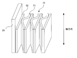
- FIG. 1 is a perspective view of a catalyst supporting substrate according to the present embodiment.
- FIG. 2 is an enlarged perspective view of a part of the catalyst supporting substrate.
- the catalyst supporting substrate 1 includes a honeycomb body 10 and an outer cylinder 20.
- a heat-resistant alloy can be used for the catalyst supporting substrate 1.
- Fe-20Cr-5Al stainless steel and those joined with a brazing material having high heat resistance can be used.
- various heat-resistant stainless steels containing Al in the alloy composition can also be used.
- the foil used for the substrate 1 for supporting a catalyst contains 15 to 25% by mass of Cr and 2 to 8% by mass of Al.
- an Fe-18Cr-3Al alloy, an Fe-20Cr-8Al alloy, or the like can be used as the heat resistant alloy.
- the catalyst supporting substrate 1 can be installed in an exhaust gas path of a vehicle.
- the honeycomb body 10 is formed in a roll shape by winding a long and wavy corrugated foil 51 and a flat flat foil 52 around the axial direction in multiple layers.
- a plurality of channels having the corrugated foil 51 and the flat foil 52 as side walls are formed by winding the corrugated foil 51 and the flat foil 52 in multiple layers.
- Each of the plurality of flow paths extends in the axial direction of the catalyst supporting substrate 1.
- the outer cylinder 20 is formed in a cylindrical shape and is disposed at a position surrounding the outer peripheral surface in the radial direction of the honeycomb body 10. The inner surface of the outer cylinder 20 and the outer surface of the honeycomb body 10 are partially joined, and details will be described later.
- the catalyst supporting substrate 1 is not limited to a circular cross section.
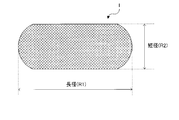
- the catalyst-supporting substrate 1 can be formed in other shapes such as an oval shape, an oval shape, a race track (hereinafter referred to as RT) shape.
- FIG. 8 is a schematic view of an RT-shaped honeycomb body as viewed from the axial direction, in which R1 has a major axis and R2 has a minor axis.
- the honeycomb body 10 may carry a catalyst.
- a washcoat solution (a solution containing ⁇ -alumina, an additive, and a noble metal catalyst as a component) is supplied to the flow path of the honeycomb body 10 and baked by high-temperature heat treatment so that the honeycomb body 10 can carry it.
- the exhaust gas is purified by reacting with the catalyst when passing through the flow path of the honeycomb body 10.
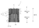
- FIG. 3 is a cross-sectional view of the catalyst supporting substrate 1 cut along the axial direction.
- a bonding layer 30 is formed between the outer peripheral surface of the honeycomb body 10 and the inner peripheral surface of the outer cylinder 20, and the honeycomb body 10 and the outer cylinder 20 are partially bonded via the bonding layer 30. .
- the bonding layer 30 is formed only in the exit end region 10a of the honeycomb body 10, and is formed at a plurality of predetermined intervals in the circumferential direction of the honeycomb body 10 (outer cylinder 20). However, the bonding layer 30 can also be formed in the entire circumferential direction of the honeycomb body 10 (outer cylinder 20) in the outlet side end region 10a.
- a Ni-based brazing material having high heat resistance can be used for the bonding layer 30, a Ni-based brazing material having high heat resistance can be used.
- the bonding layer 30 extends in the axial direction from the exit end of the honeycomb body 10.
- P is 50 mm or less, and preferably 45 mm or less.
- FIG. 4 is a cross-sectional view of a catalyst-supporting base material of a comparative example, and corresponds to FIG.
- bonding layer 300 is formed at the entrance end of honeycomb body 100 or at the center in the axial direction of honeycomb body 100.
- the honeycomb body in the temperature raising process has the following temperature characteristics. The exhaust gas flows into the flow path of the honeycomb body from the entrance side end of the catalyst supporting substrate, and gradually decreases in temperature while exchanging heat with the honeycomb body.
- the temperature distribution in the axial direction of the catalyst-carrying substrate in the temperature raising process is not uniform, and the temperature gradually decreases from the entrance side end to the exit side end. That is, as the catalyst-carrying base material is closer to the entrance side, the temperature change becomes larger. Therefore, when the bonding layer 300 is formed at the entrance-side end and the axial center of the catalyst-carrying base material, the thermal durability is improved. Deteriorate. Therefore, in the configuration of the comparative example, the honeycomb body 100 is easily detached from the outer cylinder 200 by repeating the temperature raising process.
- the bonding layer 30 at the outlet end portion of the honeycomb body in order to enhance the thermal durability of the catalyst supporting substrate.
- the dimension in the axial direction of the bonding layer 30 is lengthened, the constrained region of the honeycomb body 10 is increased due to the increase in the bonding area, and the axial end of the bonding layer 30 is changed to the inlet end where the temperature change is large. Since it approaches, cold durability becomes worse.
- the formation region of the bonding layer 30 is limited to the outlet end portion, and the upper limit value of the axial length P of the bonding layer 30 is limited to 50 mm. That is, by satisfying these conditions, the region where the bonding layer 30 is formed is limited to a region where the temperature change is small, so that the thermal durability can be improved.
- the corrugated foil 51 and the flat foil 52 in the inlet side joining portion 11 and the outer circumference joining portion 12 of the honeycomb body 10 are joined to each other in order to further improve the thermal durability of the catalyst supporting substrate 1.
- a brazing material can be used for joining.
- As the brazing material a Ni-based brazing material having high heat resistance can be used.
- the entrance-side joined portion 11 is formed to extend in the axial direction from the entrance-side end portion of the honeycomb body 10, where X is 5 mm or more and 50% or less of the total axial length. It is a length and is formed over the entire radial layer of the honeycomb body 10. In FIG. 3, a region where the entrance side joint portion 11 is formed is surrounded by a one-dot chain line.
- the outer peripheral joint 12 extends from the outermost periphery of the honeycomb body 10 in the radial direction to two or more layers in the radial direction and from the axial end 11a of the inlet joint 11 to the outlet end of the honeycomb body 10 to 1/3 or less of the total number of layers. It is formed over. In FIG. 3, a region where the outer peripheral joint portion 12 is formed is surrounded by a two-dot chain line.
- the axial direction end portion 11a of the entrance side joint portion 11 is an opposite end portion different from the entrance side end portion in the axial direction of the entrance side joint portion 11, in other words, the lower surface of the entrance side joint portion 11. That is.
- the total number of layers is the number of corrugated foils 51 from the center of the honeycomb body 10 to the outermost periphery.
- the time required for the catalyst supporting substrate 1 to be exposed to the hot exhaust gas at the center portion is longer than that of the outer peripheral portion. Therefore, thermal strain due to a temperature difference between the central portion and the outer peripheral portion of the honeycomb body 10 occurs, and further, foil elongation occurs in the central portion, so thermal strain due to foil elongation also occurs.
- the corrugated foil 51 and the flat foil 52 in the entrance-side joined portion 11 and the outer peripheral joint portion 12 of the honeycomb body 10 to each other, the corrugated foil 51 and the flat foil 52 in the central portion 10b in the radial direction on the exit side are independent of each other. The stress can be relaxed. Thereby, the cold-heat durability of the base material 1 for catalyst support can be improved more.
- the inventor diligently studied the structure of the honeycomb body 10 that improves the impact durability as well as the above-described cold and heat durability, and has obtained the following knowledge.
- a vibration is applied to the catalyst supporting substrate 1 when the vehicle travels, and this vibration propagates to the bonding layer 30 via the corrugated foil 51, thereby reducing the bonding force between the honeycomb body 10 and the outer cylinder 20.
- the axial length P of the bonding layer 30 is limited to 50 mm or less in order to increase the thermal durability, so that the impact durability is increased by increasing the axial length of the bonding layer 30. Can not be increased.
- the present inventor has intensively studied a structure that makes it difficult for vibration applied to the honeycomb body 10 to propagate to the bonding layer 30, and provides an impact relaxation portion 13 having a phase difference in the axial direction before and after at least a part of the corrugated foil 51. I found out.
- FIG. FIG. 5 is a development view of a part of the impact relaxation portion 13 formed on the corrugated foil 51.
- the corrugated foil 51 is alternately bent before and after the radial direction, and the impact relaxation portion 13 is configured by making the wave phases different before and after the axial direction. That is, the shock relaxation unit 13 is configured by an offset structure in which the phases of waves arranged in the axial direction are shifted by a predetermined range.
- the impact relaxation unit 13 the impact force can be cut (relaxed) between waves having different phases. Thereby, both the heat resistance and the impact durability of the substrate 1 for supporting a catalyst can be achieved.
- the exhaust gas collides with the wall portion of the honeycomb body 10 and is stirred by adopting the offset structure, the purification performance can be improved.
- the impact reducing portion 13 is provided in the entrance-side joint portion 11, whereby the effect of improving the purification performance can be enhanced.
- the lower limit of the axial length P of the bonding layer 30 can be limited to 2 mm by providing the impact relaxation portion 13 described above. That is, if at least 2 mm of the axial length P of the bonding layer 30 is ensured, impact durability can be ensured.
- the axial length P of the bonding layer 30 satisfies the following formula (A), and preferably satisfies the following formula (B).
- the impact mitigation part 13 in the present embodiment is formed only in the entrance side joining part 11 and the outer periphery joining part 12 of the honeycomb body 10, and the other parts of the honeycomb body 10 have the same wave phase before and after the axial direction. It is configured. In this way, by forming the joining region where the corrugated foil 51 and the flat foil 52 are joined and the impact relaxing part 13 having different wave phases before and after the axial direction are formed at overlapping positions, the impact caused by the impact relaxing part 13 is reduced.
- the relaxation effect can be enhanced. That is, in the joining region, since the wave foil 51 and the flat foil 52 are integrated, vibration is easily transmitted. Therefore, the vibration propagating to the joining layer 30 is formed by forming the impact relaxation portion 13 in the joining region. Can be more effectively suppressed.
- the joining region and the impact relaxation portion 13 are formed at overlapping positions, the joining region can be easily identified, so that the joining process can be simplified. That is, since the impact mitigating portion 13 and other regions (regions where the impact mitigating portion of the corrugated foil 51 is not provided) are easily visually distinguished from each other, the brazing range can be easily determined.
- the impact relaxation part 13 can also be extended to the external region of the entrance side joint part 11 and the outer periphery joint part 12. In this case, the manufacturing process becomes complicated because the structure of the honeycomb body 10 is complicated, but the impact force propagating to the bonding layer 30 can be more reliably mitigated.
- FIG. 6 is a cross-sectional view of a part of the impact relaxation portion 13, where one wave adjacent in the axial direction is indicated by a solid line, and the other wave is indicated by a dotted line.
- the impact relaxation portion 13 of the present embodiment is formed in a sine curve shape when viewed in the axial direction.
- T1 is an offset width
- T2 is a phase shift
- T3 is a wave pitch
- T4 is a wave height.
- the offset width T1 is the axial length of waves having the same phase.
- the offset width T1 is preferably 0.5 mm or greater and 50 mm or less. When the offset width T1 is less than 0.5 mm, the pressure loss increases.
- the phase shift T2 is the amount of phase shift between adjacent waves in the axial direction.
- the phase shift T2 is preferably 0.05 mm or more and 5 mm or less.
- the phase shift T2 is less than 0.05 mm, the overlapping area of waves adjacent in the axial direction increases, so that the impact force mitigating ability decreases.
- the phase shift T2 exceeds 5 mm, the contact area between the honeycomb body 10 and the exhaust gas becomes small, and the purification performance deteriorates.
- the wave pitch T3 is the length in the circumferential direction (circumferential direction of the honeycomb body 10) of wave peaks (or valleys).
- the half-wave length of the wave is the wave pitch T3.
- the wave pitch T3 is preferably 0.1 mm or more and 5 mm or less.
- the wave pitch T3 is less than 0.1 mm, the exhaust gas passage is narrowed and the pressure loss is increased.
- the wave pitch T3 exceeds 5 mm, the contact area between the honeycomb body 10 and the exhaust gas becomes small, and the purification performance deteriorates.
- the wave height T4 is the difference in height between the wave peaks and valleys.
- the wave height T4 is preferably not less than 0.1 mm and not more than 5 mm.
- the wave height T4 is less than 0.1 mm, the exhaust gas passage is narrowed and the pressure loss increases.
- the wave height T4 exceeds 5 mm, the contact area between the honeycomb body 10 and the exhaust gas becomes small, and the purification performance deteriorates.
- the impact relaxation portion 13 can be manufactured using, for example, the jig shown in FIG.
- FIG. 7 is a cross-sectional view of the jig, and illustrates elements that do not appear in the cross-section as seen through dotted lines.
- An arrow A indicates the rotation direction of the jig
- an arrow B indicates the conveyance direction of the base material foil that is the base material of the corrugated foil 51.
- the jig 70 is formed in a roll shape and rotates around a shaft portion 71 extending in the normal direction of the paper surface. On the outer peripheral surface of the jig 70, an uneven portion 72 corresponding to the shape of the impact relaxation portion 13 is formed.
- the concavo-convex shape portions 72 indicated by the solid line and the dotted line are formed at adjacent positions in the direction of the shaft portion 71, and each extends in the direction of the shaft portion 71.
- the jig 70 is rotated in the direction of arrow A with the concave-convex shape portion 72 in contact with the base material foil, and the base material foil is fed out in the direction of arrow B, so that the entrance side joining portion 11 of the corrugated foil 51 and The impact relaxation portion 13 can be formed in a region corresponding to the outer peripheral joint portion 12.
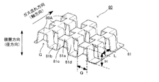
- FIG. 9 is an external perspective view of a part of the corrugated sheet.
- FIG. 10 is an external view of corrugated plates adjacent in the axial direction.
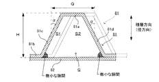
- the impact mitigating unit 80 is a continuum 80A in which a trapezoidal gas flow path G is continued in an orthogonal plane orthogonal to the axial direction, and the continuum 80A is offset (offset) in the axial direction. However, it is configured by connecting.
- the trapezoidal gas flow path G is formed between the corrugated foil 81 and the flat foil 82 that are stacked in layers.
- the corrugated foil 81 includes a first flat shape portion 81a, a second flat shape portion 81b, a first taper shape portion 81c, and a second taper shape portion 81d.
- the first and second flat shape portions 81a and 81b extend in a direction orthogonal to the axial direction, and the first flat shape portion 81a is located on the radially outer side of the honeycomb body than the second flat shape portion 81b. ing.
- the first and second taper-shaped portions 81c and 81d extend from both ends of the first flat-shaped portion 81a toward the inner side in the radial direction, and the tip end side is connected to the second flat-shaped portion 81b. Thereby, the trapezoidal gas flow path G in which the upper base and the lower base are alternately switched around the axis is continuously formed.
- the area of the gas flow path G is divided at a position corresponding to the corrugated foil 81 adjacent in the axial direction, one area is S1, and the other area is S2. It is preferable to adjust the offset amount of the corrugated foils 81 adjacent in the axial direction so that the areas S1 and S2 are different from each other. Thereby, a flow velocity difference is generated between the gas flowing into the area S1 and the area S2, respectively, and turbulent flow can be generated. By generating the turbulent flow, the area where the gas contacts the wave foil 81 and the flat foil 82 increases, and the purification performance can be further improved.
- Turbulent flow can be generated when the area S1 and the area S2 are different from each other, but it is more preferable that the following conditional expression (C) is satisfied.
- the pitch of the gas flow path G is Q
- the height of the first taper-shaped portion 81c (second taper-shaped portion 81d) is H
- the angle formed is ⁇
- the pitch Q is the length of a line connecting the midpoints of the first tapered portion 81c and the second tapered portion 81d.
- the height H of the first taper-shaped part 81c (second taper-shaped part 81d) is the height in the stacking direction (in other words, the radial direction of the honeycomb body).
- H / Q 0.15 ⁇ H / Q ⁇ 0.85 (D) 5 ° ⁇ ⁇ ⁇ 45 ° ⁇ ⁇ ⁇ ⁇ ⁇ ⁇ ⁇ ⁇ ⁇ ⁇ ⁇ (E) That is, the present inventors have found that by forming each gas flow path G in a flat shape, it is possible to relax conditions such as a flow velocity at which transition from laminar flow to turbulent flow is suppressed while suppressing an increase in pressure loss.
- H / Q satisfies the range of conditional expression (D)
- the more preferable condition of H / Q is 0.25 or more and 0.80 or less.
- H is preferably 0.1 mm or more and 10 mm or less
- S is preferably 0.1 mm or more and 10 mm or less.
- the present inventors provide the first taper-shaped portion 81c (second taper-shaped portion 81d) (that is, the shape of the gas flow path G is not a rectangle but a trapezoid), thereby suppressing an increase in pressure loss. It was found that the purification performance can be improved.
- the effect of improving the purification performance is presumed to be that the increase in the surface area of the gas flow path G due to an increase in ⁇ and the promotion of turbulent gas flow. That is, when ⁇ is 5 ° or more, turbulent flow easily occurs in the gas flow path G and the surface area is sufficiently increased, so that the purification performance is further improved.
- ⁇ By limiting ⁇ to 45 ° or less, a minute gap indicated by hatching formed between the tip of the first tapered portion 81c (second tapered portion 81d) and the flat foil 82 can be widened. .
- the gas easily flows into the gap, and the contact between the catalyst supported in the gap and the gas is ensured, so that the purification performance can be further enhanced.
- the gas flow becomes turbulent, so that the gas easily flows into the minute gap. Therefore, even if ⁇ is greater than 45 °, the purification performance is deteriorated. Can be relaxed.
- Example 1 When the length of each gas flow path G in the axial direction is L, the following conditional expression (F) is preferably satisfied.
- L 0.1 mm or more pressure loss can be reduced.
- L 100 mm or less the effect of improving the purification performance by offsetting the continuum 80A can be enhanced.
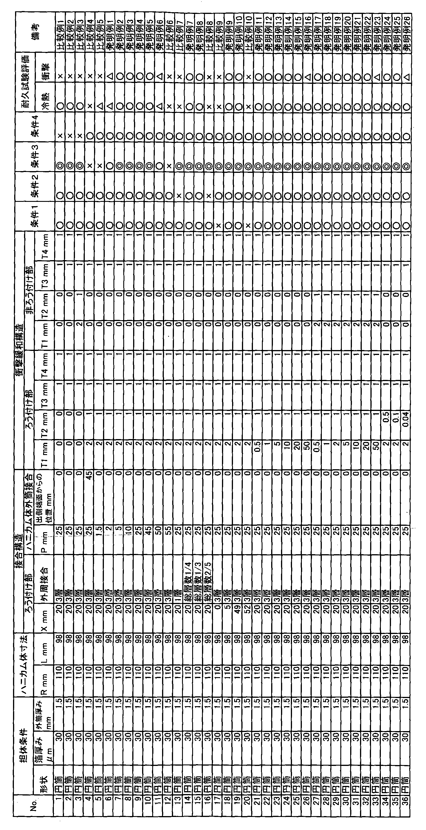
- Example 1 corresponds to Embodiment 1. Cylindrical or RT-shaped catalyst support base materials were prepared with various specifications, and the effects of the present invention were examined by evaluating the thermal durability and impact durability. Tables 1 to 3 show the various specifications and their evaluation results.
- the cold heat durability was evaluated by allowing hot air and cold air to alternately flow into the catalyst-supporting substrate, and repeatedly cooling.
- the joint between the outer cylinder and the honeycomb body is broken by repeated cold heat, and the honeycomb body falls off.
- the number of repetitions of cooling until the honeycomb body falls off is counted, and when this count is 600 times or more, it is evaluated as ⁇ because the cooling durability is very good, and the count is 400 to 600 times. In some cases, the evaluation was evaluated as “ ⁇ ” because the cooling durability was good, and in the case where the count number was less than 400, the evaluation was evaluated as “poor” because the cooling durability was poor.
- a temperature increasing process for raising the temperature to 950 ° C., a heat retaining process for keeping the temperature at 950 ° C., and a cooling process for cooling to 150 ° C. or less were performed.
- the temperature raising time was set to 1 minute, and the maximum heating rate was set to 120 ° C./second.
- the heat retention time was set to 4 minutes.
- the cooling temperature was set to 150 ° C. or lower, the cooling time was set to 2.5 minutes, and the minimum cooling rate was set to ⁇ 40 ° C./second.
- the impact durability test was conducted following the cold endurance test. While applying vibration of acceleration 100G (direction of 45 ° to the axis direction of the base material) to the catalyst-supporting base material at a frequency of 200 Hz, giving the same temperature change as in the thermal endurance test, joining between the outer cylinder and the honeycomb body The health of the department was evaluated. Evaluation is the same as in the case of the cold endurance test, and the number of repetitions of cold heat until the honeycomb body falls off is counted. If this count is 600 times or more, the impact durability is very good. When the count number is 400 to 600 times, the impact durability is evaluated as ⁇ , and when the count number is less than 400 times, the impact durability is poor. It evaluated by x.
- foil thickness refers to the total thickness of two layers of flat foil and corrugated foil.
- R is the diameter of the honeycomb body
- L is the length in the axial direction of the honeycomb body.
- the major axis and the minor axis are as shown in FIG. 8, and “L” is the length in the axial direction.
- the condition 1 is that “the entry side joined portion is formed over the entire radial layer of the honeycomb body from 5 mm to 50% of the total axial length from the entry side end of the honeycomb body. In the case of satisfying this condition 1, it was evaluated as “good”, and in the case where this condition 1 was not satisfied, it was evaluated as “poor”.
- the condition 2 is described in claim 1, wherein “the outer peripheral joint portion is not less than two layers in the radial direction from the outermost periphery of the honeycomb body, and the shaft of the inlet side joint portion is not more than 1/3 of the total number of layers. Is formed from the direction end portion to the exit end portion of the honeycomb body, and is evaluated as ⁇ when this condition 2 is satisfied, and when this condition 2 is not satisfied X was evaluated.
- the condition 3 corresponds to “2 mm ⁇ P ⁇ 50 mm” described in claim 1 and satisfies “5 mm ⁇ P ⁇ 45 mm” (that is, the numerical condition described in claim 2).
- Example 2 corresponds to the second embodiment.
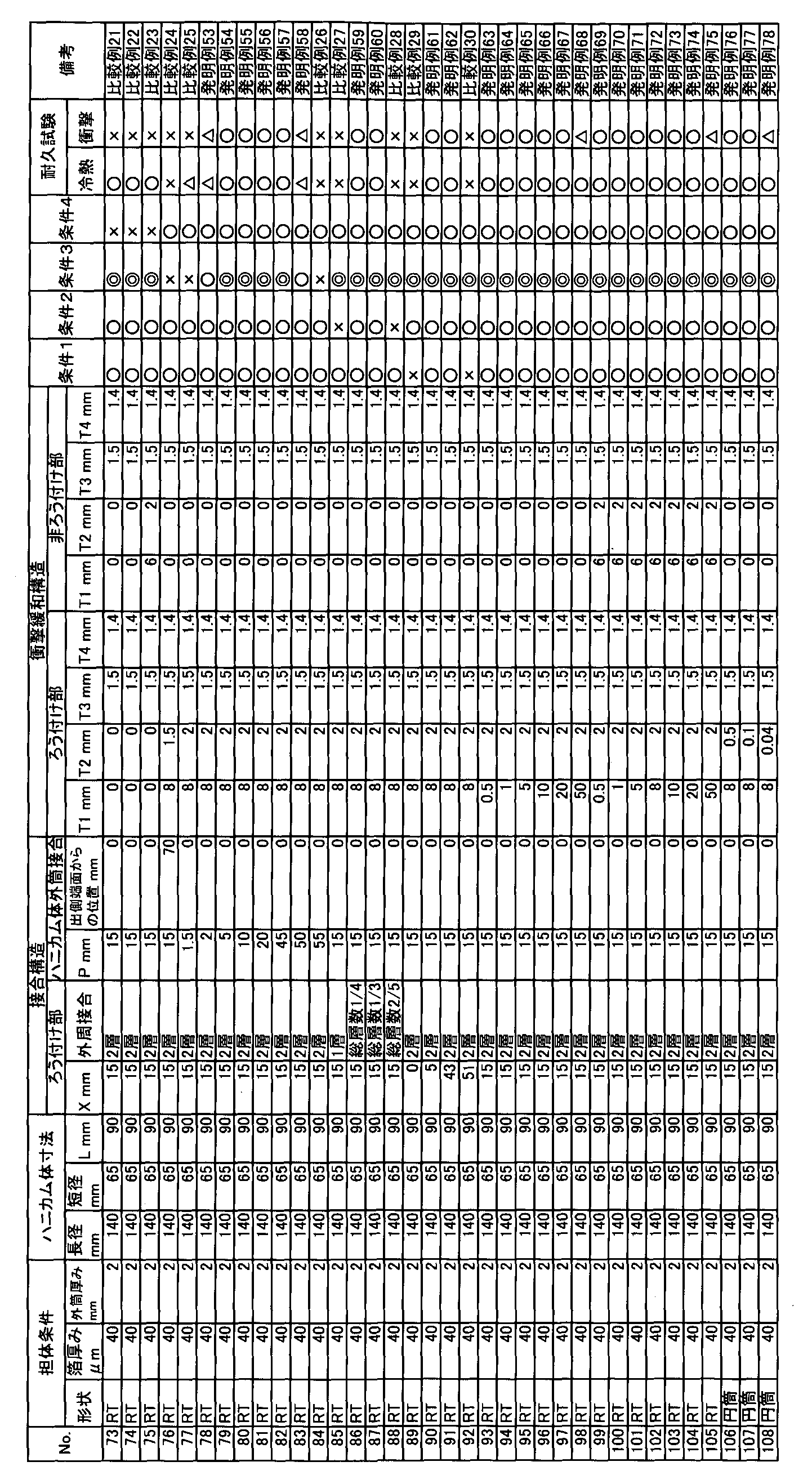
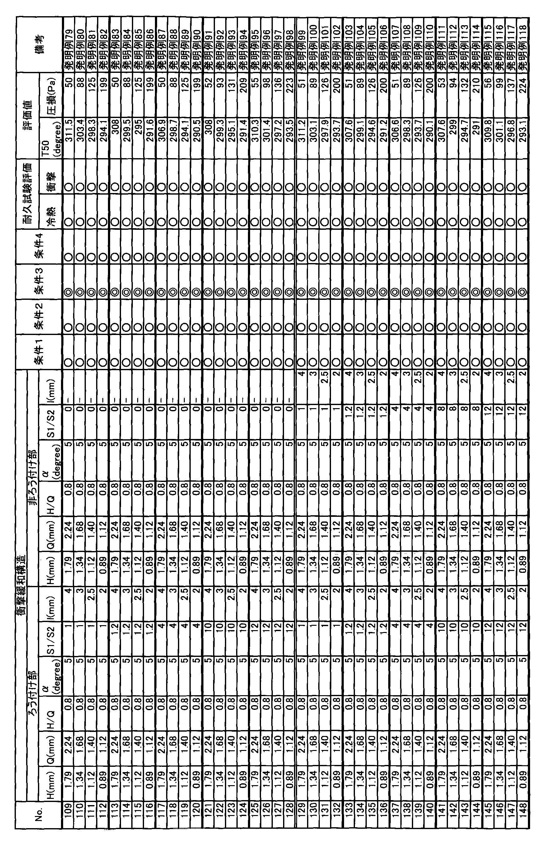
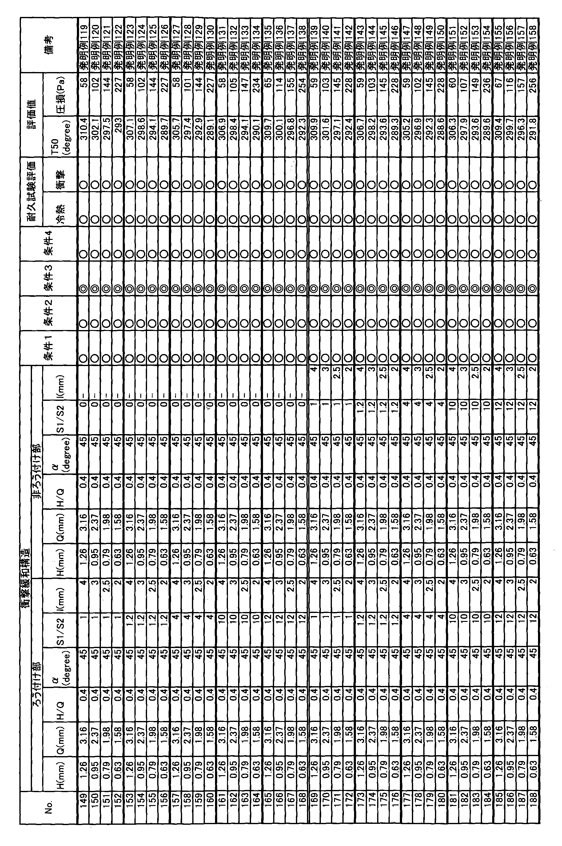
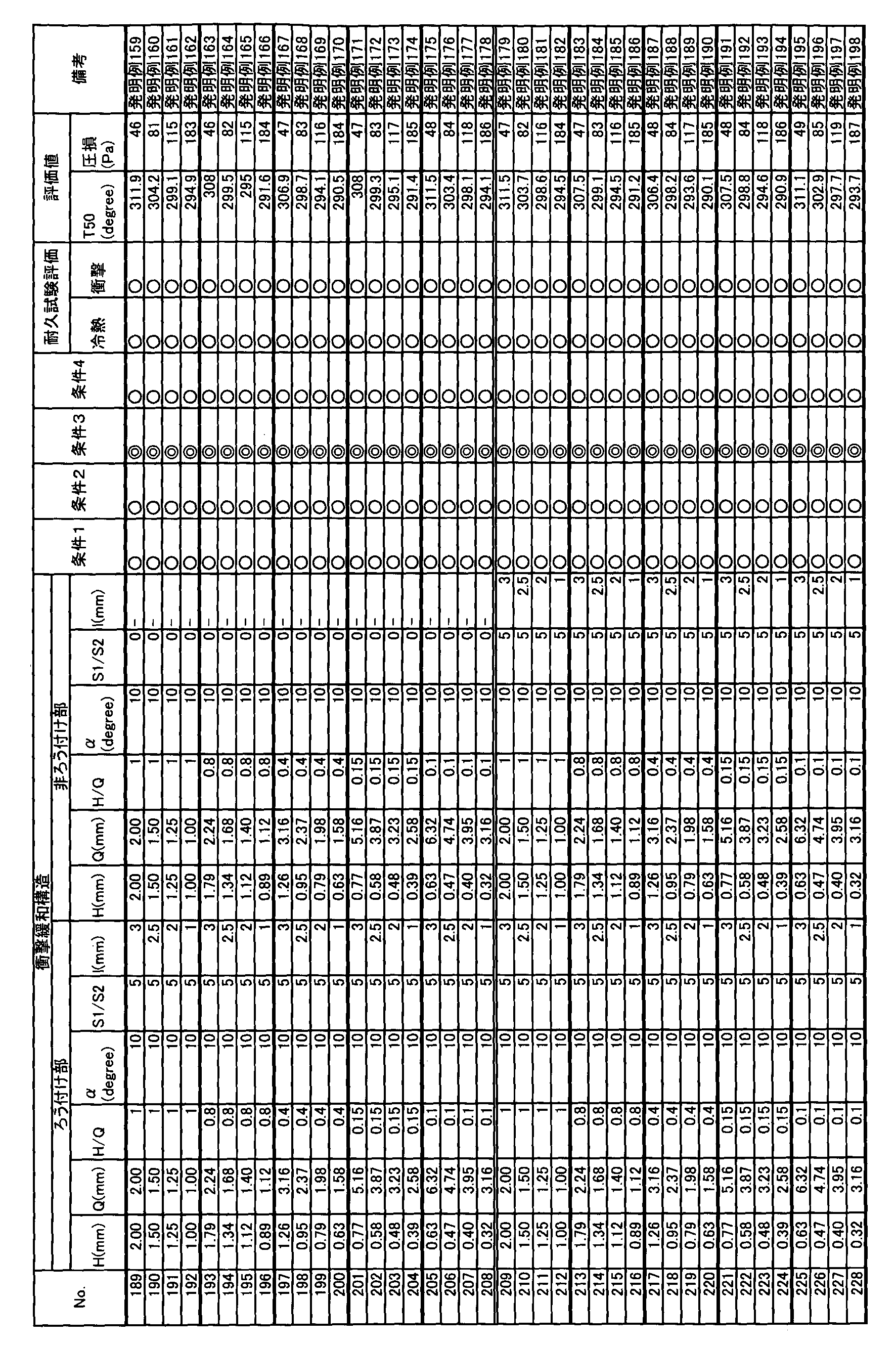
- Cylindrical and RT-shaped catalyst support base materials were prepared with various specifications, and the effects of the present invention were examined by evaluating purification performance and pressure loss.
- the catalyst was supported by the following method.
- a wash coat layer composed mainly of ceria-zirconia-alumina was formed on the prototype metal substrate. After passing the washcoat liquid through the metal substrate and removing the excess washcoat liquid, drying is performed at 180 ° C. for 1 hour, followed by baking at 500 ° C. for 2 hours, thereby forming the washcoat layer on the metal substrate. Formed at 180 g / L per volume.
- the metal carrier on which the washcoat layer was formed was immersed in distilled water to sufficiently absorb water, and then pulled up to blow off excess moisture and immersed in an aqueous solution containing palladium. By taking out and drying, 4 g / L of palladium was supported per volume of the substrate.
- Each catalyst supporting substrate was loaded into a catalyst container, and purification performance evaluation and pressure loss evaluation were performed by the following methods. At this time, the catalyst supporting substrate was exposed to an atmosphere containing 10% water vapor in advance and heated to 980 ° C., and maintained for 4 hours to perform a deterioration simulation treatment.
- the purification rate was determined by analyzing the gas composition on the entry side and the exit side. In the temperature raising process, the inlet gas temperature T50 at which the purification rate became 50% was taken as the evaluation value. In this example, T50 of the HC component was used as the evaluation value. In the pressure loss evaluation, room temperature N 2 gas was allowed to flow to the catalyst supporting substrate, and the pressure loss generated in the catalyst supporting substrate at this time was measured by the Pitot tube method. The flow rate of N 2 gas was 905 L / min in Table 4 below, 540 L / min in Table 5, and 780 L / min in Table 6.
- the catalyst-supporting base material has the following specifications.
- the honeycomb bodies shown in Table 4 had a cylindrical shape, a foil thickness of 30 ⁇ m, a diameter of 110 mm, and an axial length of 98 mm.
- the thickness of the outer cylinder of Table 4 was 1.5 mm.
- the length (namely, X) of the entrance side junction part of Table 4 was 25 mm, and the number of layers of outer periphery joining was 3 layers.
- the length P of the outer peripheral joint of the honeycomb bodies in Table 4 was 20 mm, and the position from the exit end face was 0 mm.
- the honeycomb bodies shown in Table 5 had a cylindrical shape, a foil thickness of 50 ⁇ m, a diameter of 85 mm, and an axial length of 110 mm.
- the outer cylinder thickness in Table 5 was 1.5 mm.
- the length (namely, X) of the entrance side junction part of Table 5 was 20 mm, and the number of layers of outer periphery joining was 3 layers.
- the length P of the outer peripheral joint of the honeycomb bodies in Table 5 was 25 mm, and the position from the exit end face was 0 mm.
- the honeycomb bodies shown in Table 6 had an RT shape, a foil thickness of 40 ⁇ m, a diameter of 140 mm, an axial length of 90 mm, a major axis of 140 mm, and a minor axis of 65 mm.
- the thickness of the outer cylinder in Table 6 was 2.0 mm.
- the length (namely, X) of the entrance side joining part of Table 6 was 15 mm, and the number of outer peripheral joining layers was two.
- the length P of the outer peripheral joint of the honeycomb bodies in Table 6 was 15 mm, and the position from the exit end face was 0 mm.
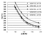
- test results in Table 4 are shown in FIG. 11, the test results in Table 5 are shown in FIG. 12, and the test results in Table 6 are shown in FIG.
Landscapes
- Chemical & Material Sciences (AREA)
- Chemical Kinetics & Catalysis (AREA)
- Engineering & Computer Science (AREA)
- Health & Medical Sciences (AREA)
- Toxicology (AREA)
- Combustion & Propulsion (AREA)
- Mechanical Engineering (AREA)
- General Engineering & Computer Science (AREA)
- Catalysts (AREA)
- Exhaust Gas Treatment By Means Of Catalyst (AREA)
- Exhaust Gas After Treatment (AREA)
Abstract
Description
(2)上記(1)の構成において、Pに下記(B)式を満足させるとよい。
上記第1及び第2の目的を達成するために、(3)前記衝撃緩和部は、台形状のガス流路を前記軸方向に対して直交する直交面内に連続させた連続体であって、この連続体を前記軸方向に位相をずらしながら連設することにより形成されており、前記軸方向視において、前記ガス流路を軸方向において隣り合う波板に対応する位置で領域分けしたときの一方の面積をS1、他方の面積をS2としたときに、面積S1及び面積S2は互いに異なることを特徴とする(1)又は(2)に記載の触媒担持用基材。
(5)上記(3)又は(4)の構成において、前記波板は、前記ガス流路の側壁を形成する一対のテーパー形状部を有しており、前記一対のテーパー形状部のそれぞれの中点を結んだ線の長さに対応する前記ガス流路のピッチをQ、前記一対のテーパー形状部の高さをH、前記径方向と前記テーパー形状部とのなす角度をαとしたときに、以下の条件式(D)又は(E)を満足する。
5°≦α≦45°・・・・・・・・・・・・・・・・・・・・・(E)
(6)上記(3)乃至(5)の構成において、前記軸方向における前記ガス流路の長さをLとしたときに、以下の条件式(F)を満足する。
以下に本実施形態を図面に基づき説明する。図1は、本実施形態に係る触媒担持用基材の斜視図である。図2は、触媒担持用基材の一部における拡大斜視図である。
5mm≦P≦45mm・・・・・・・・・・・・(B)
(A)式を満足することにより、触媒担持用基材1の冷熱耐久性及び衝撃耐久性を両立することができる。(B)式を満足することによって、上述の効果をより高めることができる。
本実施形態は、衝撃緩和部の形状が第1実施形態と異なる。図9は波板の一部における外観斜視図である。図10は軸方向において隣り合う波板の外観図である。衝撃緩和部80は、台形状のガス流路Gを軸方向に対して直交する直交面内に連続させた連続体80Aであって、この連続体80Aを軸方向に位相をずらしながら(オフセットしながら)連設することにより構成されている。台形状のガス流路Gは、層状に重ねられた波箔81と平箔82との間に形成されている。波箔81は、第1フラット形状部81a、第2フラット形状部81b、第1テーパー形状部81c及び第2テーパー形状部81dから構成されている。第1及び第2フラット形状部81a、81bは、軸方向に対して直交する方向に延びており、第1フラット形状部81aは第2フラット形状部81bよりもハニカム体の径方向外側に位置している。第1及び第2テーパー形状部81c、81dは、第1フラット形状部81aの両端から径方向内側に向かって末広がりに延びており、その先端側が第2フラット形状部81bに連設している。これにより、軸周りに上底と下底とが交互に入れ替わる台形状のガス流路Gが連続的に形成される。
S1/S2を1.2以上とすることで、乱流を生成することによる浄化性能の向上効果を十分に高めることができる。S1/S2を10以下に制限することで、面積S1の面積低下による圧力損失の増大を抑制することができる。
5°≦α≦45°・・・・・・・・・・・・・・・・・・・・・(E)
すなわち、本発明者等は、各ガス流路Gを扁平状に形成することで、圧力損失の増大を抑制しながら、層流から乱流へ遷移する流速等の条件を緩和できることを知見した。H/Qが条件式(D)の範囲を満足することで、上記緩和効果が高められ、浄化性能を向上させることができる。H/Qのより好ましい条件は、0.25以上0.80以下である。なお、Hは好ましくは0.1mm以上10mm以下であり、Sは好ましくは0.1mm以上10mm以下である。
Lを0.1mm以上にすることで、圧力損失を少なくすることができる。Lを100mm以下にすることで、連続体80Aをオフセットさせることによる浄化性能の向上効果を高めることができる。
(実施例1)
次に、実施例を示して、本発明についてより具体的に説明する。本実施例1は、実施形態1に対応している。円筒形やRT形状の触媒担持用基材を各種仕様で作成して、冷熱耐久性と衝撃耐久性を評価することで、本発明の効果を調べた。表1~表3に各種仕様と其々の評価結果を示した。

本実施例2は第2実施形態に対応している。円筒形やRT形状の触媒担持用基材を各種仕様で作成して、浄化性能と圧力損失を評価することで、本発明の効果を調べた。触媒は以下の方法で担持させた。試作した金属基材にセリア-ジルコニア-アルミナを主成分とするウォッシュコート層を形成した。金属基材にウォッシュコート液を通し、余分なウォッシュコート液を除去した後、180℃で1時間乾燥し、続いて500℃で2時間焼成することにより、金属基材にウォッシュコート層を基材体積当たりで180g/Lで形成した。このウォッシュコート層を形成した金属担体を蒸留水に浸漬して十分吸水させた後、引き上げて余分な水分を吹き払い、パラジウムを含む水溶液に浸漬した。取り出して乾燥することにより、パラジウムを基材体積当たりで4g/L担持させた。
10 ハニカム体
11 入側接合部
12 外周接合部
13 衝撃緩和部
20 外筒
30 接合層
51 波箔
52 平箔
Claims (6)
- 金属製の平箔と波箔とを積層したハニカム体と、前記ハニカム体の外周面を囲む金属製の外筒と、を備える触媒担持用基材において、
入側接合部に配置される前記平箔と前記波箔とは互いに接合されており、
前記入側接合部の軸方向端部に連設する外周接合部であって、前記外周接合部に配置される前記平箔と前記波箔とは互いに接合されており、
前記入側接合部は、前記ハニカム体の入側端部から5mm以上軸方向全長の50%以下まで、前記ハニカム体の径方向全層に亘って形成されており、
前記外周接合部は、前記ハニカム体の最外周から径方向に2層以上、総層数の1/3以下まで前記入側接合部の前記軸方向端部から前記ハニカム体の出側端部に亘って形成されており、
前記外筒及び前記ハニカム体は、前記外筒及び前記ハニカム体の間に形成される出側端部領域であって、前記ハニカム体の出側端部から前記軸方向に延びる前記出側端部領域に接合層を介在させることにより接合されており、前記接合層の前記軸方向における長さをPとしたときに、Pは下記(A)式を満足しており、
前記波板は、前記軸方向の前後で波の位相が異なる衝撃緩和部を有しており、前記衝撃緩和部は、少なくとも前記入側接合部及び前記外周接合部に対応した領域に形成されていることを特徴とする触媒担持用基材。
2mm≦P≦50mm・・・・・・・・・(A) - Pは下記(B)式を満足することを特徴とする請求項1に記載の触媒担持用基材。
5mm≦P≦45mm・・・・・・・・・(B) - 前記衝撃緩和部は、台形状のガス流路を前記軸方向に対して直交する直交面内に連続させた連続体であって、この連続体を前記軸方向に位相をずらしながら連設することにより形成されており、
前記軸方向視において、前記ガス流路を軸方向において隣り合う波板に対応する位置で領域分けしたときの一方の面積をS1、他方の面積をS2としたときに、面積S1及び面積S2は互いに異なることを特徴とする請求項1又は2に記載の触媒担持用基材。 - 前記面積S1及び前記面積S2は、以下の条件式(C)を満足することを特徴とする請求項3に記載の触媒担持用基材。
1.2≦S1/S2≦10・・・・・・・・・(C) - 前記波板は、前記ガス流路の側壁を形成する一対のテーパー形状部を有しており、
前記一対のテーパー形状部のそれぞれの中点を結んだ線の長さに対応する前記ガス流路のピッチをQ、前記一対のテーパー形状部の高さをH、前記径方向と前記テーパー形状部とのなす角度をαとしたときに、
以下の条件式(D)又は(E)を満足することを特徴とする請求項3又は4に記載の触媒担持用基材。
0.15≦H/Q≦0.85・・・・・・・・・・・・(D)
5°≦α≦45°・・・・・・・・・・・・・・・・・(E) - 前記軸方向における前記ガス流路の長さをLとしたときに、以下の条件式(F)を満足することを特徴とする請求項3乃至5のうちいずれか一つに記載の触媒担持用基材。
0.1mm≦L≦100mm・・・・・・・・・・・・(F)
Priority Applications (5)
| Application Number | Priority Date | Filing Date | Title |
|---|---|---|---|
| EP19164484.8A EP3539658B1 (en) | 2014-02-12 | 2014-12-24 | Metal substrate for catalytic converters |
| JP2015562575A JP6069538B2 (ja) | 2014-02-12 | 2014-12-24 | 触媒担持用基材 |
| CN201480061402.0A CN105705237B (zh) | 2014-02-12 | 2014-12-24 | 催化剂承载用基材 |
| EP14882382.6A EP3106222B1 (en) | 2014-02-12 | 2014-12-24 | Base material for carrying catalysts |
| US15/113,230 US10072549B2 (en) | 2014-02-12 | 2014-12-24 | Metal substrate for catalytic converters |
Applications Claiming Priority (2)
| Application Number | Priority Date | Filing Date | Title |
|---|---|---|---|
| JP2014024743 | 2014-02-12 | ||
| JP2014-024743 | 2014-02-12 |
Publications (1)
| Publication Number | Publication Date |
|---|---|
| WO2015121910A1 true WO2015121910A1 (ja) | 2015-08-20 |
Family
ID=53799681
Family Applications (1)
| Application Number | Title | Priority Date | Filing Date |
|---|---|---|---|
| PCT/JP2014/006440 Ceased WO2015121910A1 (ja) | 2014-02-12 | 2014-12-24 | 触媒担持用基材 |
Country Status (5)
| Country | Link |
|---|---|
| US (1) | US10072549B2 (ja) |
| EP (2) | EP3106222B1 (ja) |
| JP (1) | JP6069538B2 (ja) |
| CN (1) | CN105705237B (ja) |
| WO (1) | WO2015121910A1 (ja) |
Cited By (26)
| Publication number | Priority date | Publication date | Assignee | Title |
|---|---|---|---|---|
| WO2017061439A1 (ja) * | 2015-10-06 | 2017-04-13 | 新日鉄住金マテリアルズ株式会社 | 触媒担持用基材及び触媒担体 |
| CN107735176A (zh) * | 2016-01-08 | 2018-02-23 | 新日铁住金高新材料股份有限公司 | 催化剂负载用蜂窝体以及催化剂转换器 |
| CN108865089A (zh) * | 2018-08-10 | 2018-11-23 | 宁夏朔光石油科技有限公司 | 堵水体系及其施工方法 |
| DE102018100833A1 (de) | 2018-01-16 | 2019-07-18 | Umicore Ag & Co. Kg | Verfahren zur Herstellung eines SCR-Katalysators |
| DE102018100834A1 (de) | 2018-01-16 | 2019-07-18 | Umicore Ag & Co. Kg | Verfahren zur Herstellung eines SCR-Katalysators |
| JP2019198823A (ja) * | 2018-05-16 | 2019-11-21 | モリテックスチール株式会社 | メタル箔及びこれを備えた積層体 |
| WO2020165387A1 (de) | 2019-02-14 | 2020-08-20 | Umicore Ag & Co. Kg | Verfahren zur herstellung von autoabgaskatalysatoren |
| JP2020131053A (ja) * | 2019-02-13 | 2020-08-31 | 日鉄ケミカル&マテリアル株式会社 | ハニカム体、触媒担持用コンバータ及び熱交換器用ハニカム体 |
| WO2021023659A1 (de) | 2019-08-05 | 2021-02-11 | Umicore Ag & Co. Kg | Katalysatorsubstrate mit poröser beschichtung |
| DE202021103624U1 (de) | 2021-07-06 | 2022-10-14 | Umicore Ag & Co. Kg | WC Applikator |
| DE102021118803A1 (de) | 2021-07-21 | 2023-01-26 | Umicore Ag & Co. Kg | Abgasreinigungssystem zur Reinigung von Abgasen von Benzinmotoren |
| DE102021118801A1 (de) | 2021-07-21 | 2023-01-26 | Umicore Ag & Co. Kg | Abgasreinigungssystem zur Reinigung von Abgasen von Benzinmotoren |
| DE102021118802A1 (de) | 2021-07-21 | 2023-01-26 | Umicore Ag & Co. Kg | Abgasreinigungssystem zur Reinigung von Abgasen von Benzinmotoren |
| DE202023100970U1 (de) | 2023-03-01 | 2023-03-16 | Umicore Ag & Co. Kg | Beschichtungsvorrichtung |
| DE202021106828U1 (de) | 2021-12-15 | 2023-03-24 | Umicore Ag & Co. Kg | Beschichtungskammer |
| DE202023103234U1 (de) | 2023-06-13 | 2023-06-26 | Umicore Ag & Co. Kg | Beschichtungsvorrichtung |
| DE102023101779A1 (de) | 2022-04-11 | 2023-10-12 | Umicore Ag & Co. Kg | Abgassystem für überwiegend stöchiometrisch betriebene Verbrennungsmotoren aufweisend einen Katalysator zur Verminderung der Ammoniakemissionen |
| WO2023198577A1 (de) | 2022-04-11 | 2023-10-19 | Umicore Ag & Co. Kg | Abgassystem für überwiegend stöchiometrisch betriebene verbrennungsmotoren aufweisend einen katalysator zur verminderung der ammoniakemissionen |
| WO2024041907A1 (de) | 2022-08-25 | 2024-02-29 | Umicore Ag & Co. Kg | Applikator zum auftragen von beschichtungsmedium auf substrate |
| DE102022130469A1 (de) | 2022-11-17 | 2024-05-23 | Umicore Ag & Co. Kg | Verfahren und Vorrichtung zum Herstellen eines Substrats für eine Abgasnachbehandlungseinrichtung |
| DE102022134540A1 (de) | 2022-12-22 | 2024-06-27 | Umicore Ag & Co. Kg | Reformierungskatalysator |
| WO2024133611A1 (de) | 2022-12-22 | 2024-06-27 | Umicore Ag & Co. Kg | Substratmonolith aufweisend einen reformierungskatalysator |
| DE102023107627A1 (de) | 2023-03-27 | 2024-10-02 | Umicore Ag & Co. Kg | Substratmonolith aufweisend einen Reformierungskatalysator |
| DE102023117464A1 (de) | 2023-07-03 | 2025-01-09 | Umicore Ag & Co. Kg | Verfahren und Vorrichtung zum Herstellen eines Substrats für eine Abgasnachbehandlungseinrichtung |
| WO2025104217A1 (de) | 2023-11-17 | 2025-05-22 | Umicore Ag & Co. Kg | Katalytischer partikelfilter |
| JP7780588B1 (ja) * | 2024-07-31 | 2025-12-04 | 日鉄ケミカル&マテリアル株式会社 | ハニカムユニット及び触媒コンバータ |
Families Citing this family (7)
| Publication number | Priority date | Publication date | Assignee | Title |
|---|---|---|---|---|
| CN106457208A (zh) * | 2014-06-04 | 2017-02-22 | 托普索公司 | 气体处理整料制品 |
| EP3590599B1 (en) * | 2017-02-28 | 2021-12-01 | NIPPON STEEL Chemical & Material Co., Ltd. | Honeycomb substrate for catalyst support, and catalytic converter for exhaust gas purification |
| JP6340101B1 (ja) * | 2017-02-28 | 2018-06-06 | 新日鉄住金マテリアルズ株式会社 | 触媒担持用基材及び触媒担体 |
| JP6742457B1 (ja) * | 2019-02-05 | 2020-08-19 | 株式会社キャタラー | 排ガス浄化用のメタル基材及びそれを用いた排ガス浄化装置 |
| WO2021070691A1 (ja) | 2019-10-08 | 2021-04-15 | 日鉄ケミカル&マテリアル株式会社 | 排気ガスの浄化に用いられるハニカムユニット及びハニカムユニットの製造方法 |
| KR102389351B1 (ko) * | 2020-04-23 | 2022-04-21 | 주식회사 혜성피에스 | 분쇄유닛과 이것을 구비한 물질혼합장치 |
| JP6975359B1 (ja) * | 2021-07-30 | 2021-12-01 | 日鉄ケミカル&マテリアル株式会社 | 触媒担持用基材及び触媒担体 |
Citations (5)
| Publication number | Priority date | Publication date | Assignee | Title |
|---|---|---|---|---|
| JPS61115139U (ja) * | 1984-12-29 | 1986-07-21 | ||
| JPS63201631U (ja) * | 1987-06-19 | 1988-12-26 | ||
| JP2006175346A (ja) * | 2004-12-22 | 2006-07-06 | Nippon Steel Corp | 構造耐久性に優れた触媒担持用メタル担体 |
| JP2008264596A (ja) * | 2007-04-16 | 2008-11-06 | Showa Aircraft Ind Co Ltd | 排気ガス浄化用の触媒担体 |
| JP2011156505A (ja) * | 2010-02-03 | 2011-08-18 | Nippon Steel Materials Co Ltd | 触媒担体 |
Family Cites Families (11)
| Publication number | Priority date | Publication date | Assignee | Title |
|---|---|---|---|---|
| JPS61115139A (ja) | 1984-11-12 | 1986-06-02 | Nec Corp | プログラム走行時間制御方式 |
| JPS63201631A (ja) | 1987-02-17 | 1988-08-19 | Sharp Corp | カラ−表示装置の駆動方法 |
| JP2558005B2 (ja) | 1990-07-10 | 1996-11-27 | 新日本製鐵株式会社 | 良好な耐久性を有する自動車排ガス触媒用金属担体 |
| JPH0815559B2 (ja) * | 1990-11-13 | 1996-02-21 | 新日本製鐵株式会社 | 耐熱応力・耐熱疲労特性の優れたレーストラック型自動車排ガス触媒用金属担体 |
| JP3199936B2 (ja) | 1993-11-18 | 2001-08-20 | 新日本製鐵株式会社 | メタル担体 |
| JP4049501B2 (ja) * | 2000-01-24 | 2008-02-20 | 日本碍子株式会社 | セラミックス構造体 |
| US6656564B2 (en) * | 2000-08-03 | 2003-12-02 | Ngk Insulators, Ltd. | Ceramic honeycomb structure |
| JP2003080660A (ja) | 2000-10-10 | 2003-03-19 | Nippon Steel Corp | ハニカム体の製造方法 |
| EP1475150B1 (en) | 2000-10-10 | 2012-08-22 | Nippon Steel Corporation | Honeycomb body manufacturing method |
| JP5719645B2 (ja) * | 2011-03-10 | 2015-05-20 | 株式会社エフ・シー・シー | 排気ガス浄化装置 |
| JP5674531B2 (ja) | 2011-03-31 | 2015-02-25 | 本田技研工業株式会社 | 排気ガス浄化用ハニカムユニット |
-
2014
- 2014-12-24 CN CN201480061402.0A patent/CN105705237B/zh active Active
- 2014-12-24 WO PCT/JP2014/006440 patent/WO2015121910A1/ja not_active Ceased
- 2014-12-24 EP EP14882382.6A patent/EP3106222B1/en active Active
- 2014-12-24 US US15/113,230 patent/US10072549B2/en active Active
- 2014-12-24 JP JP2015562575A patent/JP6069538B2/ja active Active
- 2014-12-24 EP EP19164484.8A patent/EP3539658B1/en active Active
Patent Citations (5)
| Publication number | Priority date | Publication date | Assignee | Title |
|---|---|---|---|---|
| JPS61115139U (ja) * | 1984-12-29 | 1986-07-21 | ||
| JPS63201631U (ja) * | 1987-06-19 | 1988-12-26 | ||
| JP2006175346A (ja) * | 2004-12-22 | 2006-07-06 | Nippon Steel Corp | 構造耐久性に優れた触媒担持用メタル担体 |
| JP2008264596A (ja) * | 2007-04-16 | 2008-11-06 | Showa Aircraft Ind Co Ltd | 排気ガス浄化用の触媒担体 |
| JP2011156505A (ja) * | 2010-02-03 | 2011-08-18 | Nippon Steel Materials Co Ltd | 触媒担体 |
Cited By (62)
| Publication number | Priority date | Publication date | Assignee | Title |
|---|---|---|---|---|
| EP3360612A4 (en) * | 2015-10-06 | 2019-04-24 | Nippon Steel & Sumikin Materials Co., Ltd. | CARRIER BASE FOR A CATALYST AND CATALYST CARRIER |
| JPWO2017061439A1 (ja) * | 2015-10-06 | 2018-02-01 | 新日鉄住金マテリアルズ株式会社 | 触媒担持用基材及び触媒担体 |
| CN107683176A (zh) * | 2015-10-06 | 2018-02-09 | 新日铁住金高新材料股份有限公司 | 催化剂负载用基材及催化剂载体 |
| WO2017061439A1 (ja) * | 2015-10-06 | 2017-04-13 | 新日鉄住金マテリアルズ株式会社 | 触媒担持用基材及び触媒担体 |
| US10458305B2 (en) | 2015-10-06 | 2019-10-29 | Nippon Steel Chemical & Material Co., Ltd. | Metal substrate for catalytic converter and catalyst carrier |
| CN107735176B (zh) * | 2016-01-08 | 2020-02-21 | 日铁化学材料株式会社 | 催化剂负载用蜂窝体以及催化剂转换器 |
| EP3401011A4 (en) * | 2016-01-08 | 2019-06-05 | Nippon Steel & Sumikin Materials Co., Ltd. | WABENKÖRPER FOR CARRYING A CATALYST AND CATALYTIC CONVERTER |
| CN107735176A (zh) * | 2016-01-08 | 2018-02-23 | 新日铁住金高新材料股份有限公司 | 催化剂负载用蜂窝体以及催化剂转换器 |
| US11400443B2 (en) | 2018-01-16 | 2022-08-02 | Umicore Ag & Co. Kg | Ultrasound-assisted method for producing an SCR catalytic converter |
| DE102018100834A1 (de) | 2018-01-16 | 2019-07-18 | Umicore Ag & Co. Kg | Verfahren zur Herstellung eines SCR-Katalysators |
| WO2019141719A1 (de) | 2018-01-16 | 2019-07-25 | Umicore Ag & Co. Kg | Ultraschall-assistiertes verfahren zur herstellung eines scr-katalysators |
| WO2019141718A1 (de) | 2018-01-16 | 2019-07-25 | Umicore Ag & Co. Kg | Verfahren zur herstellung eines scr-katalysators mittels vortrocknung |
| DE102018100833A1 (de) | 2018-01-16 | 2019-07-18 | Umicore Ag & Co. Kg | Verfahren zur Herstellung eines SCR-Katalysators |
| US11230955B2 (en) | 2018-01-16 | 2022-01-25 | Umicore Ag & Co. Kg | Method for producing an SCR catalytic converter by way of pre-drying |
| JP2019198823A (ja) * | 2018-05-16 | 2019-11-21 | モリテックスチール株式会社 | メタル箔及びこれを備えた積層体 |
| WO2019221169A1 (ja) * | 2018-05-16 | 2019-11-21 | モリテックスチール株式会社 | メタルシート及びこれを備えた積層体 |
| CN108865089A (zh) * | 2018-08-10 | 2018-11-23 | 宁夏朔光石油科技有限公司 | 堵水体系及其施工方法 |
| CN108865089B (zh) * | 2018-08-10 | 2019-06-25 | 宁夏朔光石油科技有限公司 | 堵水体系及其施工方法 |
| JP7254551B2 (ja) | 2019-02-13 | 2023-04-10 | 日鉄ケミカル&マテリアル株式会社 | ハニカム体、触媒担持用コンバータ及び熱交換器用ハニカム体 |
| JP2020131053A (ja) * | 2019-02-13 | 2020-08-31 | 日鉄ケミカル&マテリアル株式会社 | ハニカム体、触媒担持用コンバータ及び熱交換器用ハニカム体 |
| WO2020165387A1 (de) | 2019-02-14 | 2020-08-20 | Umicore Ag & Co. Kg | Verfahren zur herstellung von autoabgaskatalysatoren |
| DE102019103765B4 (de) | 2019-02-14 | 2023-01-12 | Umicore Ag & Co. Kg | Verfahren zur Herstellung von Autoabgaskatalysatoren |
| WO2021023659A1 (de) | 2019-08-05 | 2021-02-11 | Umicore Ag & Co. Kg | Katalysatorsubstrate mit poröser beschichtung |
| DE202021103624U1 (de) | 2021-07-06 | 2022-10-14 | Umicore Ag & Co. Kg | WC Applikator |
| DE102021118803A1 (de) | 2021-07-21 | 2023-01-26 | Umicore Ag & Co. Kg | Abgasreinigungssystem zur Reinigung von Abgasen von Benzinmotoren |
| DE102021118801A1 (de) | 2021-07-21 | 2023-01-26 | Umicore Ag & Co. Kg | Abgasreinigungssystem zur Reinigung von Abgasen von Benzinmotoren |
| DE102021118802A1 (de) | 2021-07-21 | 2023-01-26 | Umicore Ag & Co. Kg | Abgasreinigungssystem zur Reinigung von Abgasen von Benzinmotoren |
| WO2023001863A1 (de) | 2021-07-21 | 2023-01-26 | Umicore Ag & Co. Kg | Abgasreinigungssystem zur reinigung von abgasen von benzinmotoren |
| WO2023001865A1 (de) | 2021-07-21 | 2023-01-26 | Umicore Ag & Co. Kg | Abgasreinigungssystem zur reinigung von abgasen von benzinmotoren |
| WO2023001617A1 (de) | 2021-07-21 | 2023-01-26 | Umicore Ag & Co. Kg | Abgasreinigungssystem zur reinigung von abgasen von benzinmotoren |
| US12410741B2 (en) | 2021-07-21 | 2025-09-09 | Umicore Ag & Co. Kg | Exhaust gas purification system for purifying exhaust gases of gasoline engines |
| US12188392B2 (en) | 2021-07-21 | 2025-01-07 | Umicore Ag & Co. Kg | Exhaust gas system for purifying exhaust gases of gasoline engine |
| US12247505B2 (en) | 2021-07-21 | 2025-03-11 | Umicore Ag & Co. Kg | Exhaust gas purification system for purifying exhaust gases of internal combustion engines |
| DE202021106828U1 (de) | 2021-12-15 | 2023-03-24 | Umicore Ag & Co. Kg | Beschichtungskammer |
| WO2023198574A1 (de) | 2022-04-11 | 2023-10-19 | Umicore Ag & Co. Kg | Abgassystem für überwiegend stöchiometrisch betriebene verbrennungsmotoren aufweisend einen katalysator zur verminderung der ammoniakemissionen |
| WO2023198569A1 (de) | 2022-04-11 | 2023-10-19 | Umicore Ag & Co. Kg | Ammoniaksperrkatalysator für stöchiometrische verbrennungsmotoren |
| DE102023101763A1 (de) | 2022-04-11 | 2023-10-12 | Umicore Ag & Co. Kg | Abgassystem für überwiegend stöchiometrisch betriebene Verbrennungsmotoren aufweisend einen Katalysator zur Verminderung der Ammoniakemissionen |
| WO2023198577A1 (de) | 2022-04-11 | 2023-10-19 | Umicore Ag & Co. Kg | Abgassystem für überwiegend stöchiometrisch betriebene verbrennungsmotoren aufweisend einen katalysator zur verminderung der ammoniakemissionen |
| WO2023198570A1 (de) | 2022-04-11 | 2023-10-19 | Umicore Ag & Co. Kg | Abgassystem für überwiegend stöchiometrisch betriebene verbrennungsmotoren aufweisend einen katalysator zur verminderung der ammoniakemissionen |
| WO2023198571A1 (de) | 2022-04-11 | 2023-10-19 | Umicore Ag & Co. Kg | Abgassystem für überwiegend stöchiometrisch betriebene verbrennungsmotoren aufweisend einen katalysator zur verminderung der ammoniakemissionen |
| DE102023101768A1 (de) | 2022-04-11 | 2023-10-12 | Umicore Ag & Co. Kg | Abgassystem für überwiegend stöchiometrisch betriebene Verbrennungsmotoren aufweisend einen Katalysator zur Verminderung der Ammoniakemissionen |
| WO2023198575A1 (de) | 2022-04-11 | 2023-10-19 | Umicore Ag & Co. Kg | Abgassystem für überwiegend stöchiometrisch betriebene verbrennungsmotoren aufweisend einen katalysator zur verminderung der ammoniakemissionen |
| DE102023101779A1 (de) | 2022-04-11 | 2023-10-12 | Umicore Ag & Co. Kg | Abgassystem für überwiegend stöchiometrisch betriebene Verbrennungsmotoren aufweisend einen Katalysator zur Verminderung der Ammoniakemissionen |
| WO2023198573A1 (de) | 2022-04-11 | 2023-10-19 | Umicore Ag & Co. Kg | Abgassystem für überwiegend stöchiometrisch betriebene verbrennungsmotoren aufweisend einen katalysator zur verminderung der ammoniakemissionen |
| WO2023198572A1 (de) | 2022-04-11 | 2023-10-19 | Umicore Ag & Co. Kg | Abgassystem für überwiegend stöchiometrisch betriebene verbrennungsmotoren aufweisend einen katalysator zur verminderung der ammoniakemissionen |
| DE102023101772A1 (de) | 2022-04-11 | 2023-10-12 | Umicore Ag & Co. Kg | Abgassystem für überwiegend stöchiometrisch betriebene Verbrennungsmotoren aufweisend einen Katalysator zur Verminderung der Ammoniakemissionen |
| DE102022121499A1 (de) | 2022-08-25 | 2024-03-07 | Umicore Ag & Co. Kg | Applikator zum Auftragen von Beschichtungsmedium auf Substrate |
| WO2024041907A1 (de) | 2022-08-25 | 2024-02-29 | Umicore Ag & Co. Kg | Applikator zum auftragen von beschichtungsmedium auf substrate |
| DE102022130469A1 (de) | 2022-11-17 | 2024-05-23 | Umicore Ag & Co. Kg | Verfahren und Vorrichtung zum Herstellen eines Substrats für eine Abgasnachbehandlungseinrichtung |
| DE102022134540A1 (de) | 2022-12-22 | 2024-06-27 | Umicore Ag & Co. Kg | Reformierungskatalysator |
| WO2024133613A1 (de) | 2022-12-22 | 2024-06-27 | Umicore Ag & Co. Kg | Reformierungskatalysator, herstellung desselben, verwendung desselben zur erzeugung von wasserstoff sowie vorrichtung zur stromerzeugung |
| WO2024133611A1 (de) | 2022-12-22 | 2024-06-27 | Umicore Ag & Co. Kg | Substratmonolith aufweisend einen reformierungskatalysator |
| WO2024179974A2 (de) | 2023-03-01 | 2024-09-06 | Umicore Ag & Co. Kg | Beschichtungsvorrichtung |
| DE202023100970U1 (de) | 2023-03-01 | 2023-03-16 | Umicore Ag & Co. Kg | Beschichtungsvorrichtung |
| DE102023107627A1 (de) | 2023-03-27 | 2024-10-02 | Umicore Ag & Co. Kg | Substratmonolith aufweisend einen Reformierungskatalysator |
| WO2024256218A1 (de) | 2023-06-13 | 2024-12-19 | Umicore Ag & Co. Kg | Beschichtungsstation |
| DE202023103234U1 (de) | 2023-06-13 | 2023-06-26 | Umicore Ag & Co. Kg | Beschichtungsvorrichtung |
| DE102023117464A1 (de) | 2023-07-03 | 2025-01-09 | Umicore Ag & Co. Kg | Verfahren und Vorrichtung zum Herstellen eines Substrats für eine Abgasnachbehandlungseinrichtung |
| WO2025104217A1 (de) | 2023-11-17 | 2025-05-22 | Umicore Ag & Co. Kg | Katalytischer partikelfilter |
| DE102023132075A1 (de) * | 2023-11-17 | 2025-05-22 | Umicore Ag & Co. Kg | Katalytischer Partikelfilter |
| JP7780588B1 (ja) * | 2024-07-31 | 2025-12-04 | 日鉄ケミカル&マテリアル株式会社 | ハニカムユニット及び触媒コンバータ |
| WO2026029078A1 (ja) * | 2024-07-31 | 2026-02-05 | 日鉄ケミカル&マテリアル株式会社 | ハニカムユニット及び触媒コンバータ |
Also Published As
| Publication number | Publication date |
|---|---|
| EP3106222B1 (en) | 2019-07-03 |
| EP3106222A1 (en) | 2016-12-21 |
| EP3539658B1 (en) | 2020-09-09 |
| JP6069538B2 (ja) | 2017-02-01 |
| CN105705237B (zh) | 2018-01-30 |
| EP3539658A1 (en) | 2019-09-18 |
| US10072549B2 (en) | 2018-09-11 |
| JPWO2015121910A1 (ja) | 2017-03-30 |
| CN105705237A (zh) | 2016-06-22 |
| EP3106222A4 (en) | 2017-08-30 |
| US20170002711A1 (en) | 2017-01-05 |
Similar Documents
| Publication | Publication Date | Title |
|---|---|---|
| JP6069538B2 (ja) | 触媒担持用基材 | |
| JPH05301049A (ja) | 金属製ハニカム担体 | |
| RU2516716C2 (ru) | Сотовый элемент и способ изготовления паяного сотового элемента | |
| CN114502824B (zh) | 用于净化废气的蜂窝单元以及蜂窝单元的制造方法 | |
| JP3215866B2 (ja) | 排気ガス浄化用触媒に用いる金属製担体の製造方法 | |
| US20240418115A1 (en) | Honeycomb body for exhaust-gas aftertreatment, having slotted metal foils | |
| JP2008264596A (ja) | 排気ガス浄化用の触媒担体 | |
| CN118401305A (zh) | 用于废气净化的催化剂负载用基材 | |
| JP6367729B2 (ja) | ハニカム体及び触媒担体 | |
| JP2015208742A (ja) | キャタライザエレメント及びキャタライザ | |
| JP6275933B2 (ja) | ハニカム体及び触媒コンバータ | |
| JP2025024959A (ja) | ハニカムユニットおよび触媒コンバータ | |
| JP6396748B2 (ja) | 触媒担持用基材、触媒担体、触媒担持用基材の製造方法及び触媒担体の製造方法 | |
| JP2013015110A (ja) | 排ガス触媒装置におけるハニカム体の製造方法並びにこの方法によって製造されたハニカム体並びにこのハニカム体を適用した排ガス触媒装置 | |
| JP7254551B2 (ja) | ハニカム体、触媒担持用コンバータ及び熱交換器用ハニカム体 | |
| JP2025155024A (ja) | 触媒装置 | |
| CN121866109A (zh) | 用于废气净化的蜂窝单元及催化转换器 | |
| JP6247165B2 (ja) | 排気浄化装置 | |
| JP2004169601A (ja) | 排気ガス浄化装置 | |
| JP6139961B2 (ja) | ハニカム構造体 | |
| JP2026022723A (ja) | ハニカムユニット及び触媒コンバータ | |
| JP2009183844A (ja) | 金属触媒担体 | |
| JPH03174221A (ja) | 排気ガス浄化装置 | |
| JP2007218142A (ja) | 排気ガスの浄化方法 | |
| JPH0730314U (ja) | 排ガス触媒装置 |
Legal Events
| Date | Code | Title | Description |
|---|---|---|---|
| 121 | Ep: the epo has been informed by wipo that ep was designated in this application |
Ref document number: 14882382 Country of ref document: EP Kind code of ref document: A1 |
|
| ENP | Entry into the national phase |
Ref document number: 2015562575 Country of ref document: JP Kind code of ref document: A |
|
| WWE | Wipo information: entry into national phase |
Ref document number: 15113230 Country of ref document: US |
|
| REEP | Request for entry into the european phase |
Ref document number: 2014882382 Country of ref document: EP |
|
| WWE | Wipo information: entry into national phase |
Ref document number: 2014882382 Country of ref document: EP |
|
| NENP | Non-entry into the national phase |
Ref country code: DE |