WO2015121973A1 - Dispositif de détection de position de conteneur et système de commande de grue - Google Patents
Dispositif de détection de position de conteneur et système de commande de grue Download PDFInfo
- Publication number
- WO2015121973A1 WO2015121973A1 PCT/JP2014/053476 JP2014053476W WO2015121973A1 WO 2015121973 A1 WO2015121973 A1 WO 2015121973A1 JP 2014053476 W JP2014053476 W JP 2014053476W WO 2015121973 A1 WO2015121973 A1 WO 2015121973A1
- Authority
- WO
- WIPO (PCT)
- Prior art keywords
- container
- arrangement position
- detection light
- container arrangement
- light
- Prior art date
- Legal status (The legal status is an assumption and is not a legal conclusion. Google has not performed a legal analysis and makes no representation as to the accuracy of the status listed.)
- Ceased
Links
Images





Classifications
-
- B—PERFORMING OPERATIONS; TRANSPORTING
- B66—HOISTING; LIFTING; HAULING
- B66C—CRANES; LOAD-ENGAGING ELEMENTS OR DEVICES FOR CRANES, CAPSTANS, WINCHES, OR TACKLES
- B66C13/00—Other constructional features or details
- B66C13/04—Auxiliary devices for controlling movements of suspended loads, or preventing cable slack
- B66C13/08—Auxiliary devices for controlling movements of suspended loads, or preventing cable slack for depositing loads in desired attitudes or positions
- B66C13/085—Auxiliary devices for controlling movements of suspended loads, or preventing cable slack for depositing loads in desired attitudes or positions electrical
-
- B—PERFORMING OPERATIONS; TRANSPORTING
- B66—HOISTING; LIFTING; HAULING
- B66C—CRANES; LOAD-ENGAGING ELEMENTS OR DEVICES FOR CRANES, CAPSTANS, WINCHES, OR TACKLES
- B66C13/00—Other constructional features or details
- B66C13/16—Applications of indicating, registering, or weighing devices
-
- B—PERFORMING OPERATIONS; TRANSPORTING
- B66—HOISTING; LIFTING; HAULING
- B66C—CRANES; LOAD-ENGAGING ELEMENTS OR DEVICES FOR CRANES, CAPSTANS, WINCHES, OR TACKLES
- B66C13/00—Other constructional features or details
- B66C13/18—Control systems or devices
- B66C13/22—Control systems or devices for electric drives
-
- B—PERFORMING OPERATIONS; TRANSPORTING
- B66—HOISTING; LIFTING; HAULING
- B66C—CRANES; LOAD-ENGAGING ELEMENTS OR DEVICES FOR CRANES, CAPSTANS, WINCHES, OR TACKLES
- B66C19/00—Cranes comprising trolleys or crabs running on fixed or movable bridges or gantries
- B66C19/007—Cranes comprising trolleys or crabs running on fixed or movable bridges or gantries for containers
Definitions
- This invention relates to a container arrangement position detection device and a crane control system.
- Patent Document 1 discloses a container arrangement position detection device that detects a position where a container should be arranged in a container yard.
- an image pickup unit such as a CCD camera is installed on a spreader of a crane arranged in a container yard, and the upper edge of the container is detected by this image pickup unit, and the position where the container is to be placed (container Locating position).
- the conventional container arrangement position detection device only evaluates the amount of horizontal displacement on the image of the imaging unit, and can evaluate it as a physical distance (for example, how many mm are displaced). Absent. And the distance of the height direction to a packing destination target container or a target position mark is not known. Therefore, in the container arrangement position detection device, it is difficult to control the suspension tool or the container held by the suspension tool so that the container is accurately placed on the target position without deviation. Also, if the amount of light at the imaging location is insufficient and the influence of noise or disturbance contained in the image data acquired by the imaging unit is large, or if there is a lot of noise or disturbance itself, the container placement position must be set correctly. It becomes difficult to ask for. For example, after rain, there is a problem that sunlight is reflected on rainwater collected in a container yard or the like, and the container arrangement position cannot be obtained accurately.
- An object of the present invention is to provide a container arrangement position detection device and a crane control system capable of accurately and stably obtaining a container arrangement position.
- the container arrangement position detection device is a container arrangement position detection device that detects a position where a container is to be arranged in a container yard, and is an already installed container already arranged in the container yard.
- a detection light irradiating unit that irradiates detection light from above so as to cross the upper edge of the first detection light irradiated to the suspended container by imaging the irradiation range of the detection light obliquely from above and the existing container
- a first imaging unit that detects the second detection light applied to the upper surface of the first imaging unit, and a container arrangement position determination unit that obtains a container arrangement position based on the first detection light and the second detection light.
- the container arrangement position determination unit in the container arrangement position detection device of the first aspect is configured to detect the second detection light detected by the first imaging unit.
- the height of the upper edge of the existing container may be obtained based on the position.
- the container arrangement position determination unit in the container arrangement position detection device determines the amount of deviation between the first detection light and the second detection light. Based on this, the height distance between the suspended container and the upper edge of the existing container may be obtained.
- the container arrangement position detection device is provided in the container yard by imaging the container yard in the container arrangement position detection device according to any one of the first to third aspects.
- a second imaging unit that detects a mark corresponding to the container arrangement position, and the container arrangement position determination unit may obtain the container arrangement position in the container yard based on the position of the mark.
- the first imaging unit in the container arrangement position detection device of the fourth aspect may also serve as the second imaging unit.
- the container arrangement position detection device may include an illumination unit that illuminates the imaging range of the second imaging unit in the container arrangement position detection device according to the fourth or fifth aspect. .
- the illumination light emitted from the illumination unit is set in the same wavelength band as the detection light in the container arrangement position detection device of the sixth aspect. It may be.
- the wavelength band in the container arrangement position detection device of the seventh aspect may be set to an absorption band of sunlight.
- the detection light irradiation section in the container arrangement position detection device is adjacent to the container arrangement position. Then, the detection light may be irradiated so as to cross the upper edge of the already installed adjacent container, and the container arrangement position determining unit may detect the position of the already installed adjacent container.
- the crane control system includes a crane that moves a container in a container yard, the container arrangement position detection device according to any one of the first to ninth aspects, and the container arrangement position detection. And a control device that controls the crane based on the container arrangement position obtained by the device.
- the container arrangement position detection apparatus described above can accurately determine the container arrangement position while having resistance to surrounding disturbances and noise.
- the crane control system mentioned above can arrange a container correctly in a container arrangement position.
- FIG. 1 is a diagram showing a crane control system 1 according to an embodiment of the present invention.
- the crane control system 1 includes a crane 5, a container arrangement position detection device 20, a control device 50, and the like.
- the crane 5 is a mechanical device that holds the container C1 that is a suspended load and moves toward the container arrangement position A in the container yard G.
- the container arrangement position detection apparatus 20 is an apparatus that detects a position (container arrangement position A) where the container C1 is arranged.
- the control device 50 is a device that controls the crane 5 based on the container placement position A obtained by the container placement position detection device 20.
- the crane 5 is a tire-type yard bridge crane for stacking containers C1.
- the crane 5 includes a portal crane traveling machine body 10 and a tire-type traveling device 11 that causes the crane traveling machine body 10 to travel in the X direction on a trackless surface.
- the crane traveling machine body 10 has a pair of upper beams 12 extending in parallel in the horizontal direction (Y direction).
- a traverse trolley 13 that moves along the upper beam 12 is attached to these upper beams 12.
- the traversing trolley 13 includes a hoisting device 14 that moves the spreader 16 in the vertical direction (Z direction) via the suspension wire 15.
- the hoisting device 14 moves the spreader 16 suspended from the suspension wire 15 in the vertical direction by winding or unwinding the suspension wire 15.
- the spreader 16 can hold (grip) the container C1 in a detachable manner.
- the spreader 16 is a planar member that substantially matches the shape of the upper surface of the container C1.
- Two container arrangement position detection devices 20 are attached downward on one long side 16 a extending in the X direction of the spreader 16.
- Two container arrangement position detectors 20 are also attached downward to the other long side 16b parallel to the long side 16a.
- the four container arrangement position detection devices 20 have the same configuration.
- the control device 50 is placed on the crane traveling machine body 10.
- Four container arrangement position detection devices 20 are connected to the control device 50 via signal cables (not shown).
- the arrangement position of the container C1 described above is a rectangular range on the upper surface of the container C2.
- the arrangement position of the container C1 described above is set to a rectangular range that is the same shape as the upper surface of the container C2 that is determined in advance when there is no container. In general, by marking the ground, the driver can visually check the rectangular range.
- the purpose of the crane control system 1 to which the present invention is applied is to place the container C1 which is a suspended container without shifting from the arrangement position of the container C1. In order to realize this, the crane control system 1 needs to accurately and reliably detect the relative positional relationship between the container C1 and the container arrangement position.
- FIG. 2 is a diagram showing a schematic configuration of the container arrangement position detection device 20 according to the embodiment of the present invention, and is a view of the container arrangement position detection device 20 viewed from the Y direction.
- the container arrangement position detection device 20 includes a laser projector 25, an illuminator 26, a CCD camera 27, and a transmission filter 28 that matches the wavelength of these light sources.
- the laser projector (detection light irradiation unit) 25 irradiates a thin sheet-like detection light L (slit light) downward from above.
- the detection light L is a sheet-like laser beam that spreads in the Y direction, and is irradiated in the Z direction.
- the detection light L needs to have an intensity that can be distinguished from reflected light from sunlight.
- the illuminator (illumination unit) 26 is illumination using an LED or the like that irradiates illumination light R downward from above.
- the illumination light R is irradiated in the Z direction in a beam shape (spot shape).
- the wavelengths of these laser beams (detection light L) and illumination light R are set in an absorption band of sunlight. Thereby, the influence of the reflected light by sunlight is reduced, and stable detection can be realized.
- the laser projector 25 and the illuminator 26 are disposed adjacent to each other.
- the CCD camera 27 is attached facing downward.
- the CCD camera 27 images the irradiation range of the detection light L and the illumination light R.
- the CCD camera 27 serves as both a camera that captures the reflected light of the detection light L and a camera that captures the reflected light of the illumination light R.
- the CCD camera (first imaging unit, second imaging unit) 27 is spaced from the laser projector 25 and is inclined with respect to the laser projector 25.
- the image data picked up by the CCD camera 27 is output toward the container arrangement position determination unit 55 mounted on the control device 50.
- FIG. 3A is a view of the detection light L emitted from the laser projector 25 as seen from the Y direction.
- FIG. 3B is a view of the detection light L emitted from the laser projector 25 as seen from the X direction.
- FIG. 4A is a diagram illustrating an image (imaging range) of reflected light of the detection light L captured by the CCD camera 27 when the height distance is long.
- FIG. 4B is a diagram illustrating an image (imaging range) of reflected light of the detection light L captured by the CCD camera 27 when the height distance is short.
- the detection light L from the laser projector 25 is irradiated toward the container C2 that is already placed in the container yard G.
- the detection light L is irradiated so as to cross the side C1S of the container C1 that is a suspended container and the upper edge E of the container (existing container) C2 that is already arranged in the container yard G. Further, the end portion of the detection light L is irradiated to the container yard G.
- the detection light L is divided into three by the container C1 and the container C2. More specifically, the detection light L is divided into a first detection light L1 and a second detection light L2 with the lower end of the container C1 as a boundary.
- the first detection light L1 is reflected light of the detection light L irradiated on the container C1.
- the second detection light L2 is reflected light of the detection light L irradiated on the upper surface of the container C2.
- the third detection light L3 is reflected light of the detection light L irradiated to the container yard G.
- the third detection light L3 does not necessarily need to be clearly imaged, as long as the boundary with the second detection light L2 can be distinguished.
- the CCD camera 27 images the reflected light of the detection light L that is irradiated and reflected toward the upper surface of the container C2.
- the CCD camera 27 images the first detection light L1, the second detection light L2, and the third detection light L3.
- the CCD camera 27 is separated from the laser projector 25 and is inclined with respect to the laser projector 25. For this reason, as shown to FIG. 4A, the 1st detection light L1, the 2nd detection light L2, and the 3rd detection light L3 are imaged separately in the direction corresponding to a X direction.
- the container arrangement position determination unit 55 obtains a position (container arrangement position A) where the container C1 held by the crane 5 should be arranged based on the image data captured by the CCD camera 27. Specifically, the container arrangement position determination unit 55 obtains a distance H1 in the height direction between the CCD camera 27 and the container C2 based on the distance ⁇ from the image origin of the second detection light L2. Then, based on the length ⁇ of the second detection light L2, the horizontal relative displacement amount D between the container C1 and the container C2 is obtained. The distance between the laser projector 25 and the CCD camera 27 and the angle formed (the tilt angle of the CCD camera 27) and the viewing angle ⁇ of the CCD camera 27 are known. As can be seen from FIGS.
- the container arrangement position determination unit 55 determines the distance H2 in the height direction between the lower surface of the container C1 gripped by the crane 5 and the container C2 based on the image data captured by the CCD camera 27 on the image. Obtained from ⁇ .
- This distance H2 can be easily obtained using the same proportional relationship as H1.
- a crane for container handling has no means for measuring the height of the suspended container C1, and therefore there is no way to measure the distance until the container C1 is landed on the container C2.
- the container arrangement position determination unit 55 accurately determines the distance in the height direction between the container C1 and the container C2 based on the distance ⁇ on the image between the first detection light L1 and the second detection light L2. You can ask for it.
- the operation time of the crane 5 can be shortened.
- FIG. 5A is a view of the illumination light R emitted from the illuminator 26 as seen from the X direction.
- FIG. 5B is a view of the illumination light R emitted from the illuminator 26 as seen from the Y direction.
- FIG. 6A is a diagram illustrating an image (imaging range) of reflected light of the illumination light R captured by the CCD camera 27 when the height distance is long.
- FIG. 6B is a diagram illustrating an image (imaging range) of reflected light of the illumination light R captured by the CCD camera 27 when the height distance is short.
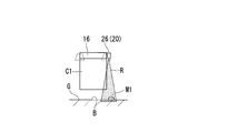
- the illumination light R from the illuminator 26 is irradiated toward the container yard G.
- the illumination light R is applied to the mark M1 installed in the container yard G.
- the mark M1 is a mark provided in the container yard G corresponding to the container arrangement position B.
- a diffusion plate is used for the mark M1. Since the light reflected by the mark M1 diffuses, the reflected light always enters the CCD camera 27. For this reason, even if the irradiation angle of the illumination light R to the mark M1 changes, the intensity of the reflected light (illumination light R) imaged by the CCD camera 27 is difficult to change.
- the CCD camera 27 can stably image the mark M1 irradiated with the illumination light R from the illuminator 26. Further, since the light reflected by the mark M1 is diffused, disturbance light such as sunlight is difficult to enter the CCD camera 27. Therefore, the mark M1 can be stably imaged by the CCD camera 27.
- the CCD camera 27 images the illumination light R that is irradiated and reflected toward the container yard G. As shown in FIGS. 6A and 6B, the CCD camera 27 images the reflected light of the illumination light R reflected by the mark M1 on the container yard G.
- the container arrangement position determination unit 55 obtains a position (container arrangement position B) where the container C1 held by the crane 5 should be arranged based on the image data captured by the CCD camera 27. Specifically, the container arrangement position determination unit 55 obtains the position of the mark M1 from the position of the reflected light of the illumination light R imaged by the CCD camera 27. The container arrangement position determination unit 55 obtains the container arrangement position B from the position in the X direction and the position in the Y direction of the mark M1. The container placement position determination unit 55 obtains a position where the container C1 is placed on the floor.
- the distance in the height direction (position in the Z direction) from the ground (container yard G) of the spreader 16 in which the container arrangement position detecting device 20 is installed is measured by a spreader position measuring device (not shown).
- a spreader position measuring device not shown.
- the distance and the angle formed by the CCD camera 27 with respect to the spreader 16 (inclination angle of the CCD camera 27) and the viewing angle of the CCD camera 27 are also known. Therefore, the distances in the X and Y directions between the CCD camera 27 and the mark M1 are geometrically determined from the mark positions P and Q on the image, and the relative relationship between the container C1 and the container arrangement position B can be more easily obtained. Distance is required.
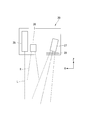
- FIG. 7 is a diagram illustrating a state in which the detection light L of the laser projector 25 is applied to the container C3.
- a container (already installed adjacent container) C3 is already arranged adjacent to the container arrangement positions A and B. For this reason, it is necessary to prevent the container C1 from colliding with the container C3 when the container C1 is arranged at the container arrangement positions A and B by the crane 5. Therefore, the container arrangement position detection device 20 irradiates the container C3 as well as the container C2 with the detection light L from the laser projector 25.
- the detection light L is irradiated so as to cross the upper edges E of the containers C2 and C3 already arranged in the container yard G.
- the CCD camera 27 images the fourth detection light L4 that is irradiated and reflected on the upper surface of the container C3.
- the fourth detection light L4 is captured at a position different from the first detection light L1, the second detection light L2, and the third detection light L3. For this reason, the container arrangement position determination unit 55 can obtain the position of the upper edge E of the container C3 based on the position of the fourth detection light L4.
- the container arrangement position determining unit 55 can detect the presence of the container C3 that becomes an obstacle when the containers C1 are stacked. Therefore, the control device 50 can reliably avoid the collision between the container C1 and the container C3 by controlling the crane 5 based on the position of the upper edge E of the container C3 obtained by the container arrangement position determination unit 55.
- the present invention is not limited to the above-described embodiment, and includes various modifications made to the above-described embodiment without departing from the spirit of the present invention. That is, the specific shapes, configurations, and the like given in the embodiment are merely examples, and can be changed as appropriate.
- a total of four container arrangement position detection devices 20 are installed on the long sides 16a and 16b of the spreader 16, but the present invention is not limited to this.
- the number and the installation position of the container arrangement position detection device 20 can be arbitrarily set.
- Detecting light L is not limited to sheet-like light along the Y direction. It may be a sheet-like light along the X direction. Of the four container arrangement position detection devices 20, the two container arrangement position detection devices 20 emit sheet-like detection light L along the X direction, and the remaining two container arrangement position detection devices 20 You may make it irradiate the sheet-like detection light L along a Y direction. Thereby, four sides of the upper surface of the container C2 can be detected.
- the two rectangular marks M1 are arranged in the container yard G, but the present invention is not limited to this.
- the shape and number of marks provided in the container yard G corresponding to the container arrangement position B can be arbitrarily set.
- This invention is the crane control system 1 and the container arrangement position detection device.
Landscapes
- Engineering & Computer Science (AREA)
- Mechanical Engineering (AREA)
- Automation & Control Theory (AREA)
- Control And Safety Of Cranes (AREA)
Abstract
Priority Applications (6)
| Application Number | Priority Date | Filing Date | Title |
|---|---|---|---|
| JP2015505755A JP5950022B2 (ja) | 2014-02-14 | 2014-02-14 | コンテナ配置位置検出装置、クレーン制御システム |
| HK16104384.8A HK1216414B (en) | 2014-02-14 | Container position detecting device and crane control system | |
| PCT/JP2014/053476 WO2015121973A1 (fr) | 2014-02-14 | 2014-02-14 | Dispositif de détection de position de conteneur et système de commande de grue |
| KR1020157001787A KR101704309B1 (ko) | 2014-02-14 | 2014-02-14 | 컨테이너 배치 위치 검출 장치, 크레인 제어 시스템 |
| SG11201500575UA SG11201500575UA (en) | 2014-02-14 | 2014-02-14 | Container position detecting device and crane control system |
| CN201480001926.0A CN104995123B (zh) | 2014-02-14 | 2014-02-14 | 集装箱配置位置检测装置、吊车控制系统 |
Applications Claiming Priority (1)
| Application Number | Priority Date | Filing Date | Title |
|---|---|---|---|
| PCT/JP2014/053476 WO2015121973A1 (fr) | 2014-02-14 | 2014-02-14 | Dispositif de détection de position de conteneur et système de commande de grue |
Publications (1)
| Publication Number | Publication Date |
|---|---|
| WO2015121973A1 true WO2015121973A1 (fr) | 2015-08-20 |
Family
ID=53799739
Family Applications (1)
| Application Number | Title | Priority Date | Filing Date |
|---|---|---|---|
| PCT/JP2014/053476 Ceased WO2015121973A1 (fr) | 2014-02-14 | 2014-02-14 | Dispositif de détection de position de conteneur et système de commande de grue |
Country Status (5)
| Country | Link |
|---|---|
| JP (1) | JP5950022B2 (fr) |
| KR (1) | KR101704309B1 (fr) |
| CN (1) | CN104995123B (fr) |
| SG (1) | SG11201500575UA (fr) |
| WO (1) | WO2015121973A1 (fr) |
Cited By (5)
| Publication number | Priority date | Publication date | Assignee | Title |
|---|---|---|---|---|
| WO2018073168A1 (fr) * | 2016-10-18 | 2018-04-26 | Konecranes Global Corporation | Procédé de positionnement automatique d'un chariot cavalier pour conteneurs et chariot cavalier correspondant |
| CN109455622A (zh) * | 2017-12-15 | 2019-03-12 | 天津埃特维科技有限公司 | 集装箱吊具的视觉识别系统以及集装箱的吊箱方法 |
| JP2020142914A (ja) * | 2019-03-08 | 2020-09-10 | 住友重機械搬送システム株式会社 | クレーン、及びクレーンの積み付け方法 |
| WO2022024670A1 (fr) * | 2020-07-30 | 2022-02-03 | 住友重機械搬送システム株式会社 | Système de grue automatique et procédé de commande de système de grue automatique |
| CN118660368A (zh) * | 2024-08-20 | 2024-09-17 | 上海知率智能科技有限公司 | 港口起吊设备的照明系统 |
Families Citing this family (4)
| Publication number | Priority date | Publication date | Assignee | Title |
|---|---|---|---|---|
| CN106809730B (zh) * | 2017-01-18 | 2019-04-09 | 北京理工大学 | 一种基于视觉的集装箱自动对接起吊系统及起吊方法 |
| CN107445067B (zh) * | 2017-08-01 | 2020-01-10 | 集美大学 | 集装箱轮胎吊自动装卸系统 |
| CN112629408B (zh) * | 2020-11-30 | 2022-11-22 | 三一海洋重工有限公司 | 对位装置和对位方法 |
| CN112978579B (zh) * | 2021-05-13 | 2021-07-23 | 新乡职业技术学院 | 一种具有防碰撞控制系统的起重机 |
Citations (6)
| Publication number | Priority date | Publication date | Assignee | Title |
|---|---|---|---|---|
| JPH0451492U (fr) * | 1990-09-10 | 1992-04-30 | ||
| JPH08193944A (ja) * | 1995-01-19 | 1996-07-30 | Tohoku Electric Power Co Inc | 路面状態検出装置 |
| JP2002527317A (ja) * | 1998-10-22 | 2002-08-27 | エービービー エービー | コンテナ荷役方法及びスタッキングターゲット上の所望の位置を選択する方法を実施する手段 |
| JP2004161475A (ja) * | 2002-11-15 | 2004-06-10 | Mitsubishi Heavy Ind Ltd | 吊荷の積み付け制御方法及び制御装置並びに荷役機械 |
| JP2006256848A (ja) * | 2005-03-18 | 2006-09-28 | Mitsui Eng & Shipbuild Co Ltd | 荷役支援方法および荷役支援システム |
| JP2008168952A (ja) * | 2007-01-05 | 2008-07-24 | Mitsubishi Heavy Ind Ltd | 位置ずれ量算出方法およびクレーン並びに搬送台車 |
Family Cites Families (6)
| Publication number | Priority date | Publication date | Assignee | Title |
|---|---|---|---|---|
| JP3785061B2 (ja) | 2000-10-27 | 2006-06-14 | 三菱重工業株式会社 | 荷役クレーンにおけるコンテナ位置検知方法及び装置並びにコンテナ着床、段積制御方法 |
| JP4598999B2 (ja) * | 2001-07-18 | 2010-12-15 | 三菱重工業株式会社 | クレーン及びクレーンの制御方法 |
| KR20060097972A (ko) * | 2005-03-08 | 2006-09-18 | 이장명 | 레이저 센서와 카메라를 이용하여 컨테이너를 들어올리고내릴 수 있는 장치 |
| CN201125130Y (zh) * | 2007-10-09 | 2008-10-01 | 上海明路绳网索具有限公司 | 一种用激光扫描的集装箱吊运防撞装置 |
| CN203284078U (zh) * | 2013-05-08 | 2013-11-13 | 北京国泰星云科技有限公司 | 集装箱码头rtg/rmg吊具防碰箱自动控制系统 |
| CN103363898B (zh) * | 2013-06-26 | 2016-04-13 | 上海振华重工电气有限公司 | 集装箱对箱检测装置 |
-
2014
- 2014-02-14 WO PCT/JP2014/053476 patent/WO2015121973A1/fr not_active Ceased
- 2014-02-14 KR KR1020157001787A patent/KR101704309B1/ko not_active Expired - Fee Related
- 2014-02-14 JP JP2015505755A patent/JP5950022B2/ja active Active
- 2014-02-14 CN CN201480001926.0A patent/CN104995123B/zh active Active
- 2014-02-14 SG SG11201500575UA patent/SG11201500575UA/en unknown
Patent Citations (6)
| Publication number | Priority date | Publication date | Assignee | Title |
|---|---|---|---|---|
| JPH0451492U (fr) * | 1990-09-10 | 1992-04-30 | ||
| JPH08193944A (ja) * | 1995-01-19 | 1996-07-30 | Tohoku Electric Power Co Inc | 路面状態検出装置 |
| JP2002527317A (ja) * | 1998-10-22 | 2002-08-27 | エービービー エービー | コンテナ荷役方法及びスタッキングターゲット上の所望の位置を選択する方法を実施する手段 |
| JP2004161475A (ja) * | 2002-11-15 | 2004-06-10 | Mitsubishi Heavy Ind Ltd | 吊荷の積み付け制御方法及び制御装置並びに荷役機械 |
| JP2006256848A (ja) * | 2005-03-18 | 2006-09-28 | Mitsui Eng & Shipbuild Co Ltd | 荷役支援方法および荷役支援システム |
| JP2008168952A (ja) * | 2007-01-05 | 2008-07-24 | Mitsubishi Heavy Ind Ltd | 位置ずれ量算出方法およびクレーン並びに搬送台車 |
Cited By (11)
| Publication number | Priority date | Publication date | Assignee | Title |
|---|---|---|---|---|
| WO2018073168A1 (fr) * | 2016-10-18 | 2018-04-26 | Konecranes Global Corporation | Procédé de positionnement automatique d'un chariot cavalier pour conteneurs et chariot cavalier correspondant |
| US11492236B2 (en) | 2016-10-18 | 2022-11-08 | Konecranes Global Corporation | Method for automatically positioning a straddle carrier for containers, and straddle carrier for this purpose |
| CN109455622A (zh) * | 2017-12-15 | 2019-03-12 | 天津埃特维科技有限公司 | 集装箱吊具的视觉识别系统以及集装箱的吊箱方法 |
| JP2020142914A (ja) * | 2019-03-08 | 2020-09-10 | 住友重機械搬送システム株式会社 | クレーン、及びクレーンの積み付け方法 |
| WO2020184025A1 (fr) * | 2019-03-08 | 2020-09-17 | 住友重機械搬送システム株式会社 | Grue et procédé de chargement avec une grue |
| CN113490635A (zh) * | 2019-03-08 | 2021-10-08 | 住友重机械搬运系统工程株式会社 | 起重机及起重机的堆放方法 |
| JP7162555B2 (ja) | 2019-03-08 | 2022-10-28 | 住友重機械搬送システム株式会社 | クレーン、及びクレーンの積み付け方法 |
| WO2022024670A1 (fr) * | 2020-07-30 | 2022-02-03 | 住友重機械搬送システム株式会社 | Système de grue automatique et procédé de commande de système de grue automatique |
| JP2022026315A (ja) * | 2020-07-30 | 2022-02-10 | 住友重機械搬送システム株式会社 | 自動クレーンシステム、及び自動クレーンシステムの制御方法 |
| JP7548749B2 (ja) | 2020-07-30 | 2024-09-10 | 住友重機械搬送システム株式会社 | 自動クレーンシステム、及び自動クレーンシステムの制御方法 |
| CN118660368A (zh) * | 2024-08-20 | 2024-09-17 | 上海知率智能科技有限公司 | 港口起吊设备的照明系统 |
Also Published As
| Publication number | Publication date |
|---|---|
| HK1216414A1 (zh) | 2016-11-11 |
| KR20150105624A (ko) | 2015-09-17 |
| JP5950022B2 (ja) | 2016-07-13 |
| KR101704309B1 (ko) | 2017-02-07 |
| JPWO2015121973A1 (ja) | 2017-03-30 |
| SG11201500575UA (en) | 2015-09-29 |
| CN104995123A (zh) | 2015-10-21 |
| CN104995123B (zh) | 2017-09-08 |
Similar Documents
| Publication | Publication Date | Title |
|---|---|---|
| JP5950022B2 (ja) | コンテナ配置位置検出装置、クレーン制御システム | |
| US10315697B2 (en) | Vehicle comprising a manoeuvring system | |
| JP5978298B2 (ja) | クレーングラップル部材の位置およびスキュー判定システムおよび方法 | |
| US7289876B2 (en) | Container crane, and method of determining and correcting a misalignment between a load-carrying frame and a transport vehicle | |
| CN1248955C (zh) | 装卸用起重机中的集装箱位置检测方法及装置、及集装箱着地、摞放控制方法 | |
| US9518845B2 (en) | Device for surveying tracks | |
| EP2871465A1 (fr) | Système d'inspection du rayonnement de type monté sur véhicule | |
| CN1989060A (zh) | 电梯螺栓检测装置、电梯装置、及移动体的位置·速度检测装置 | |
| WO2014115354A1 (fr) | Portique à conteneurs | |
| CN103030063A (zh) | 用于确定集装箱吊架用的目标位置的方法和集装箱吊架 | |
| CN104860203A (zh) | 对集装箱转运起重机上的激光扫描仪校准的方法 | |
| KR20180113154A (ko) | 함요부 검출 장치, 반송 장치, 및 함요부 검출 방법 | |
| KR102159654B1 (ko) | 센서 트롤리 및 대응하는 컨테이너 크레인 | |
| KR102438943B1 (ko) | 기준 마커를 포함하는 컨테이너 크레인 | |
| TW202237510A (zh) | 高架搬送車 | |
| JP2016094094A (ja) | 車両床下検査装置 | |
| KR101820894B1 (ko) | 크레인시스템 및 처리방법 | |
| JP3222202U (ja) | クレーンレール検査システム | |
| KR102903588B1 (ko) | 검사 시스템 | |
| JP6807131B2 (ja) | 荷役搬送装置 | |
| JP2021109771A (ja) | ターゲット、検出システムおよび検出方法 | |
| HK1216414B (en) | Container position detecting device and crane control system | |
| JP2017512731A (ja) | 光学測定装置、荷役装置、光学測定装置の保護方法および荷役装置の更改方法 | |
| JP2016218584A (ja) | 無人搬送車 | |
| CN118770814A (zh) | 托盘检测方法及四向车 |
Legal Events
| Date | Code | Title | Description |
|---|---|---|---|
| ENP | Entry into the national phase |
Ref document number: 20157001787 Country of ref document: KR Kind code of ref document: A |
|
| ENP | Entry into the national phase |
Ref document number: 2015505755 Country of ref document: JP Kind code of ref document: A |
|
| 121 | Ep: the epo has been informed by wipo that ep was designated in this application |
Ref document number: 14882608 Country of ref document: EP Kind code of ref document: A1 |
|
| NENP | Non-entry into the national phase |
Ref country code: DE |
|
| 122 | Ep: pct application non-entry in european phase |
Ref document number: 14882608 Country of ref document: EP Kind code of ref document: A1 |