WO2015121997A1 - Batterie lithium-ion - Google Patents
Batterie lithium-ion Download PDFInfo
- Publication number
- WO2015121997A1 WO2015121997A1 PCT/JP2014/053574 JP2014053574W WO2015121997A1 WO 2015121997 A1 WO2015121997 A1 WO 2015121997A1 JP 2014053574 W JP2014053574 W JP 2014053574W WO 2015121997 A1 WO2015121997 A1 WO 2015121997A1
- Authority
- WO
- WIPO (PCT)
- Prior art keywords
- internal short
- positive electrode
- negative electrode
- ion battery
- lithium ion
- Prior art date
- Legal status (The legal status is an assumption and is not a legal conclusion. Google has not performed a legal analysis and makes no representation as to the accuracy of the status listed.)
- Ceased
Links
Images



Classifications
-
- H—ELECTRICITY
- H01—ELECTRIC ELEMENTS
- H01M—PROCESSES OR MEANS, e.g. BATTERIES, FOR THE DIRECT CONVERSION OF CHEMICAL ENERGY INTO ELECTRICAL ENERGY
- H01M10/00—Secondary cells; Manufacture thereof
- H01M10/05—Accumulators with non-aqueous electrolyte
- H01M10/052—Li-accumulators
-
- H—ELECTRICITY
- H01—ELECTRIC ELEMENTS
- H01M—PROCESSES OR MEANS, e.g. BATTERIES, FOR THE DIRECT CONVERSION OF CHEMICAL ENERGY INTO ELECTRICAL ENERGY
- H01M10/00—Secondary cells; Manufacture thereof
- H01M10/05—Accumulators with non-aqueous electrolyte
- H01M10/056—Accumulators with non-aqueous electrolyte characterised by the materials used as electrolytes, e.g. mixed inorganic/organic electrolytes
- H01M10/0564—Accumulators with non-aqueous electrolyte characterised by the materials used as electrolytes, e.g. mixed inorganic/organic electrolytes the electrolyte being constituted of organic materials only
- H01M10/0566—Liquid materials
- H01M10/0567—Liquid materials characterised by the additives
-
- H—ELECTRICITY
- H01—ELECTRIC ELEMENTS
- H01M—PROCESSES OR MEANS, e.g. BATTERIES, FOR THE DIRECT CONVERSION OF CHEMICAL ENERGY INTO ELECTRICAL ENERGY
- H01M10/00—Secondary cells; Manufacture thereof
- H01M10/42—Methods or arrangements for servicing or maintenance of secondary cells or secondary half-cells
- H01M10/4235—Safety or regulating additives or arrangements in electrodes, separators or electrolyte
-
- Y—GENERAL TAGGING OF NEW TECHNOLOGICAL DEVELOPMENTS; GENERAL TAGGING OF CROSS-SECTIONAL TECHNOLOGIES SPANNING OVER SEVERAL SECTIONS OF THE IPC; TECHNICAL SUBJECTS COVERED BY FORMER USPC CROSS-REFERENCE ART COLLECTIONS [XRACs] AND DIGESTS
- Y02—TECHNOLOGIES OR APPLICATIONS FOR MITIGATION OR ADAPTATION AGAINST CLIMATE CHANGE
- Y02E—REDUCTION OF GREENHOUSE GAS [GHG] EMISSIONS, RELATED TO ENERGY GENERATION, TRANSMISSION OR DISTRIBUTION
- Y02E60/00—Enabling technologies; Technologies with a potential or indirect contribution to GHG emissions mitigation
- Y02E60/10—Energy storage using batteries
Definitions
- the present invention relates to a lithium ion battery.
- Patent Document 1 describes an example of providing a non-aqueous electrolyte secondary battery in which battery performance does not deteriorate even when metal foreign matter is mixed by using an electrolytic solution to which an amide compound having a specific structure is added. ing.
- Patent Document 2 discloses that at least one of a positive electrode plate, a negative electrode plate, a separator, and a non-aqueous electrolyte solution is organic and / or inorganic Cu corrosion inhibitor, or organic and / or inorganic.
- an inhibitor that is a Cu trapping agent By adding an inhibitor that is a Cu trapping agent, the corrosion of the copper foil used as the negative electrode current collector is suppressed, the inhibition of the battery reaction is suppressed, and a lithium secondary battery having excellent self-discharge characteristics and cycle characteristics is obtained. Examples to provide are described.
- Patent Document 1 discloses a method using an electrolytic solution to which an amide compound having a specific structure is added in a range of 0.01 wt% to 2 wt%. Are listed. However, in the method of Patent Document 1, an amide compound having a specific structure may cause a side reaction due to an oxidation-reduction reaction in the positive electrode or the negative electrode, which may deteriorate battery performance.
- Patent Document 2 discloses an organic and / or inorganic Cu corrosion inhibitor, or an organic and / or inorganic Cu. A method of adding 0.01 wt% to 10 wt% of an inhibitor as a trapping agent is described.
- the inorganic corrosion inhibitor is used in the addition method of Patent Document 2, since the solubility in the non-aqueous electrolyte is small, the undissolved fine powder is suspended and dispersed in the non-aqueous electrolyte.
- the separator hole at the interface between the separator and the negative electrode / separator may be blocked, and the movement of Li ions may be hindered. Thereby, internal resistance may increase.
- an object of the present invention is to provide a lithium ion battery that can suppress the internal short circuit failure without affecting the battery performance and can improve the reliability.
- the present invention provides a positive electrode and a negative electrode, a separator that insulates the positive electrode and the negative electrode, an electrolytic solution in which a charge / discharge reaction is performed between the positive electrode and the negative electrode, and the electrolytic solution Further, the present invention provides a lithium ion battery characterized by containing 0.0001 wt% to 0.001 wt% of an internal short circuit preventing agent that suppresses internal short circuit defects.
- the present invention it is possible to provide a lithium ion battery capable of suppressing internal short circuit failure and improving reliability without affecting battery performance.
- FIG. 1 It is a figure which shows the typical structure of a lithium ion battery. It is sectional drawing which shows the internal structure of a cylindrical lithium ion battery. It is a figure which shows the component of the previous step which comprises an electrode winding body. It is a schematic diagram which shows a mode that a positive electrode, a separator, a negative electrode, and a separator are wound around an axial center, and an electrode winding body is formed. It is a graph which shows the electric current which flows into a lithium ion battery at the time of constant voltage charge when the internal short circuit does not generate
- the constituent elements are not necessarily indispensable unless otherwise specified and apparently essential in principle. Needless to say.
- FIG. 1 is a diagram showing a schematic configuration of a lithium ion battery.
- the lithium ion battery has an outer can CS whose main material is, for example, iron (Fe) or stainless steel, and an electrolyte EL is filled in the outer can CS.
- the positive electrode plate PEP and the negative electrode plate NEP are provided to face each other, and the separator SP is provided between the positive electrode plate PEP and the negative electrode plate NEP provided to face each other. Is arranged.
- the positive electrode active material is applied to the positive electrode plate PEP, and the negative electrode active material is applied to the negative electrode plate NEP.
- the positive electrode active material is formed of a lithium-containing transition metal oxide capable of inserting / extracting lithium ions.
- the positive electrode active material include lithium-containing transition metal oxides.
- typical positive electrode active materials include, but are not limited to, lithium cobaltate, lithium nickelate, and lithium manganate.
- the positive electrode active material is a material capable of inserting / extracting lithium, and may be any lithium-containing transition metal oxide in which a sufficient amount of lithium has been previously inserted, and manganese (Mn) as a transition metal , Nickel (Ni), cobalt (Co), iron (Fe) or the like, or a material mainly composed of two or more transition metals.
- Mn manganese
- Nickel (Ni), cobalt (Co), iron (Fe) or the like or a material mainly composed of two or more transition metals.
- the crystal structure such as the spinel crystal structure and the layered crystal structure is not particularly limited as long as the above-described sites and channels are ensured.
- FIG. 1 schematically shows that the lithium-containing transition metal oxide is applied to the positive electrode plate PEP. That is, FIG. 1 shows a schematic crystal structure in which oxygen, metal atoms, and lithium are arranged as the lithium-containing transition metal oxide applied to the positive electrode plate PEP.
- This positive electrode plate PEP and the positive electrode active material constitute a positive electrode.
- the negative electrode active material is formed of a carbon material capable of inserting and removing lithium ions.
- a crystalline carbon material or an amorphous carbon material can be used.
- the negative electrode active material is not limited to these materials.
- natural graphite, various artificial graphite agents, carbon materials such as coke, and the like may be used.
- particle shape various particle shapes such as a scale shape, a spherical shape, a fiber shape, and a lump shape are applicable.
- FIG. 1 schematically shows a state in which this carbon material is applied to the negative electrode plate NEP. That is, FIG. 1 shows a schematic crystal structure in which carbon is arranged as the carbon material applied to the negative electrode plate NEP.
- the negative electrode is composed of the negative electrode plate NEP and the negative electrode active material.
- the separator SP has a function as a spacer that allows lithium ions to pass through while insulating between the positive electrode and the negative electrode and preventing electrical contact.
- a high-strength and thin microporous film has been used as the separator SP.
- This microporous membrane also has a function of preventing abnormal current due to a short circuit of the battery, rapid increase in internal pressure and temperature, and ignition.
- the current separator SP has a function as a thermal fuse for preventing a short circuit and overcharge in addition to a function of preventing electrical contact between the positive electrode and the negative electrode and allowing lithium ions to pass therethrough. become. The safety of the lithium ion battery can be maintained by the shutdown function of the microporous membrane.
- separator SP when a lithium ion battery causes an external short circuit for some reason, there is a risk that a large current flows instantaneously but the temperature rises abnormally due to Joule heat.
- a microporous membrane is used as the separator SP, the microporous membrane closes the pores (microporous) in the vicinity of the melting point of the membrane material, so that lithium ions can permeate between the positive electrode and the negative electrode. Can be blocked.
- separator SP As separator SP comprised from this microporous film
- PE polyethylene
- PP polypropylene
- a nonaqueous electrolytic solution is used as the electrolytic solution EL in which a charge / discharge reaction is performed between the positive electrode and the negative electrode.
- the lithium ion battery is a battery that performs charging / discharging by using insertion / extraction of lithium ions in an active material, and lithium ions move in the electrolyte EL.
- Lithium is a strong reducing agent and reacts violently with water to generate hydrogen gas. Therefore, in a lithium ion battery in which lithium ions move in the electrolytic solution EL, an aqueous solution cannot be used as the electrolytic solution EL unlike a conventional battery. For this reason, in the lithium ion battery, a non-aqueous electrolyte is used as the electrolyte EL.
- LiPF 6, LiClO 4, LiAsF 6, LiBF 4, LiB (C 6 H 5) 4, CH 3 SO 3 Li, CF 3 SO 3 Li , etc., and mixtures thereof can be used.
- organic solvent examples include ethylene carbonate, dimethyl carbonate, propylene carbonate, diethyl carbonate, 1,2-dimethoxyethane, 1,2-diethoxyethane, ⁇ -butyrolactone, tetrahydrofuran, 1,3-dioxolane, 4-methyl- 1,3 dioxolane, diethyl ether, sulfolane, methyl sulfolane, acetonitrile, propionitrile, etc., or a mixture thereof can be used.
- the lithium ion battery is configured as described above, and the charging / discharging mechanism will be described below.
- the charging mechanism will be described.
- a charger CU is connected between the positive electrode and the negative electrode.
- lithium ions inserted in the positive electrode active material are desorbed and released into the electrolyte EL.
- the lithium ions are desorbed from the positive electrode active material, whereby electrons flow from the positive electrode to the charger.
- the lithium ions released into the electrolytic solution EL move through the electrolytic solution EL, pass through the separator SP made of a microporous film, and reach the negative electrode.
- the lithium ions that have reached the negative electrode are inserted into the negative electrode active material constituting the negative electrode. At this time, when lithium ions are inserted into the negative electrode active material, electrons flow into the negative electrode. In this way, charging is completed as electrons move from the positive electrode to the negative electrode via the charger CU.
- a current can flow from the positive electrode to the negative electrode to drive the load.
- charging / discharging can be performed by inserting / extracting lithium ions between the positive electrode active material and the negative electrode active material.
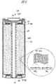
- FIG. 2 is a cross-sectional view showing the internal structure of a cylindrical lithium ion battery LIB.
- an electrode winding body WRF including a positive electrode PEL, separators SP1 and SP2, and a negative electrode NEL is formed inside a cylindrical outer can CS having a bottom.
- the electrode winding body WRF is stacked so as to sandwich the separator SP1 (SP2) between the positive electrode PEL and the negative electrode NEL, and is wound around the axis CR in the center of the outer can CS. .
- the negative electrode NEL is electrically connected to the negative electrode lead plate NT provided at the bottom of the outer can CS
- the positive electrode PEL is electrically connected to the positive electrode lead plate PT provided at the upper portion of the outer can CS.
- An electrolyte is injected into the electrode winding body formed inside the outer can CS.
- the outer can CS is sealed with a battery lid CAP.
- the positive electrode PEL is formed by applying a coating liquid containing the positive electrode active material PAS and a binder (binder) to the positive electrode plate (positive electrode current collector) PEP, drying it, and then pressurizing it.
- a plurality of rectangular positive electrode current collecting tabs PTAB are formed at the upper end portion of the positive electrode PEL, and the plurality of positive electrode current collecting tabs PTAB are connected to the positive electrode current collecting ring PR.
- the positive electrode current collection ring PR is electrically connected to the positive electrode lead plate PT. Therefore, the positive electrode PEL is electrically connected to the positive electrode lead plate PT via the positive electrode current collecting tab PTAB and the positive electrode current collecting ring PR.
- the plurality of positive electrode current collecting tabs PTAB are provided in order to reduce the resistance of the positive electrode PEL and to quickly extract current.
- the positive electrode active material PAS constituting the positive electrode PEL for example, the above-described materials represented by lithium cobaltate, lithium nickelate, lithium manganate and the like can be used.
- the binder for example, polyvinyl fluoride, polyvinylidene fluoride, polytetrafluoroethylene, or the like can be used.
- a metal foil or a net-like metal made of a conductive metal such as aluminum is used for example.
- the negative electrode NEL is formed by applying a coating liquid containing the negative electrode active material NAS and a binder (binder) to the negative electrode plate (negative electrode current collector) NEP and drying it, followed by pressurization.
- a plurality of rectangular negative electrode current collecting tabs NTAB are formed at the lower end of the negative electrode NEL, and the plurality of negative electrode current collecting tabs NTAB are connected to the negative electrode current collecting ring NR. And this negative electrode current collection ring NR is electrically connected with the negative electrode lead board NT. Therefore, the negative electrode NEL is electrically connected to the negative electrode lead plate NT via the negative electrode current collecting tab NTAB and the negative electrode current collecting ring NR.
- the negative electrode active material NAS constituting the negative electrode NEL for example, the above-described materials typified by carbon materials can be used.
- the binder for example, polyvinylidene fluoride, polytetrafluoroethylene, or the like can be used.
- a metal foil made of a conductive metal such as copper or a mesh metal is used for the negative electrode plate.
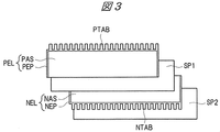
- FIG. 3 is a diagram showing components in a previous stage constituting the electrode winding body.
- the components constituting the electrode winding body are a positive electrode PEL, a separator SP1, a negative electrode NEL, and a separator SP2.
- the positive electrode PEL has a structure in which the positive electrode active material PAS is applied to both surfaces of the positive electrode plate PEP
- the negative electrode NEL has a structure in which the negative electrode active material NAS is applied to both surfaces of the negative electrode plate NEP.
- a plurality of rectangular positive electrode current collecting tabs PTAB are formed on the upper side of the positive electrode PEL.
- a plurality of rectangular negative electrode current collecting tabs NTAB are formed on the lower side of the negative electrode NEL.
- FIG. 4 is a schematic diagram showing how the electrode wound body WRF is formed by winding the positive electrode PEL, the separator SP1, the negative electrode NEL, and the separator SP2 around the axis CR.
- the positive electrode PEL, the separator SP1, the negative electrode NEL, and the separator SP2 are wound so that the separator SP1 is sandwiched between the positive electrode PEL and the negative electrode NEL and the negative electrode NEL is sandwiched between the separator SP1 and the separator SP2. Is done.
- the positive electrode current collecting tab PTAB formed on the positive electrode PEL is arranged on the upper side of the electrode winding body WRF, while the negative electrode current collecting tab (not shown) formed on the negative electrode NEL is wound on the electrode. Located on the lower side of the body WRF.
- the electrode winding body WRF is configured as described above.
- the feature of the present embodiment is that an internal short-circuit preventing agent is added to the electrolytic solution EL. Therefore, according to the lithium ion battery in this Embodiment, even if a metal foreign material mixes, an internal short circuit can be prevented. Therefore, according to the present embodiment, it is possible to further improve the reliability of the lithium ion battery in that there is no possibility of an internal short circuit due to the metal foreign matter.
- the internal short circuit preventing agent in the present embodiment is hardly soluble in an electrolytic solution EL (non-aqueous electrolytic solution) such as nitrite, nitrate, phosphate, and chromate (internal short circuit prevention for the electrolytic solution).
- the agent has a solubility of 0.001% by weight (10 ppm) or less) and a substance that collects metal ions (coordinates with metal ions to form a complex).
- the addition concentration of the internal short circuit preventing agent is 0.0001 wt% (1 ppm) to 0.001 wt% (10 ppm).
- concentration of an internal short circuit inhibitor it is preferable to set it as the solubility with respect to the electrolyte solution of an internal short circuit inhibitor.
- the reason why the lower limit value of the addition concentration of the internal short circuit preventing agent is 0.0001% by weight or more is that the function of suppressing the internal short circuit when the addition concentration of the internal short circuit preventing agent is less than 0.0001% by weight. It is because it becomes impossible to fully exhibit. That is, the reason why the internal short circuit is suppressed by adding the internal short circuit preventing agent even if the metal foreign object is mixed is that the metal ions eluted from the metal foreign object are collected by the internal short circuit preventing agent added to the electrolyte EL. It is thought to be done.
- the concentration of the internal short-circuit preventing agent is extremely low, the effect of the internal short-circuit preventing agent is diminished and metal ions eluted from the metal foreign matter cannot be collected. For this reason, in order to fully exhibit the function of preventing the internal short circuit, there is a lower limit value for the addition concentration of the internal short circuit preventing agent.
- the addition concentration of the internal short circuit preventing agent is 0. It is confirmed that an internal short circuit can be prevented even if metallic foreign matter is mixed if it is 0.0001% by weight or more.
- the reason why the upper limit of the concentration of the internal short-circuit preventing agent is 0.001% by weight or less (preferably below the solubility of the internal short-circuit preventing agent in the electrolytic solution) is that the solid particles constituting the internal short-circuit preventing agent are the electrolytic solution. This is because the concentration can exist without being suspended and dispersed in EL. That is, when the addition concentration of the internal short-circuit preventing agent is greater than 0.001% by weight, the internal short-circuit preventing agent has low solubility in the electrolytic solution EL, so that fine particles that remain undissolved are suspended in the electrolytic solution EL. This is because it becomes turbidly dispersed and closes the fine holes provided in the separator SP1 or the separator SP2. In this case, the movement of lithium ions between the positive electrode and the negative electrode is hindered, which increases the internal resistance of the lithium ion battery, leading to performance degradation.
- the concentration of the internal short-circuit preventing agent added to the electrolytic solution EL is set to 0.0001 wt% to 0.001 wt%.
- the metal foreign matter that can prevent the internal short circuit by the internal short circuit preventing agent is an alloy mainly composed of a transition metal such as iron or nickel and a transition metal such as stainless steel.
- FIG. 5 is a graph showing the current during constant voltage charging when no internal short circuit occurs and when an internal short circuit occurs.
- graph 1 shows the experimental results when no internal short circuit occurs.
- the current decays and converges to a certain value.
- the average value of current during the charging time of 501 to 600 minutes is 7.4 ⁇ A / cm 2 .
- a graph 2 shows an experimental result in the case where one iron particle having a diameter of 100 ⁇ m is arranged between the positive electrode and the separator as a metal foreign substance and an internal short circuit is generated.
- the average value of the current during the charging time of 501 minutes to 600 minutes is 311.2 ⁇ A / cm 2 . This is a short circuit current and indicates that an internal short circuit has occurred.
- the occurrence of an internal short circuit can be determined from the value of the current flowing in the lithium ion battery during constant voltage charging.
- the average value of the current during the charging time of 501 to 600 minutes is 7.4 ⁇ A / When it was cm 2 or more, it was determined that an internal short circuit occurred.
- a positive electrode composed of an active material (lithium transition metal composite oxide: LiNi 1/3 Mn 1/3 Co 1/3 O 2 ), a conductive additive (acetylene black), a binder (polyvinylidene fluoride), carbon Negative electrode made of powder, conductive additive (graphite), binder (polyvinylidene fluoride), separator made of porous polypropylene with a thickness of 20 ⁇ m, organic solvent (ethyl carbonate, dimethyl carbonate, ethyl methyl carbonate), electrolytic salt (hexa A lithium ion battery was manufactured using an electrolytic solution made of lithium fluorophosphate.
- an active material lithium transition metal composite oxide: LiNi 1/3 Mn 1/3 Co 1/3 O 2
- a conductive additive acetylene black
- a binder polyvinylidene fluoride
- carbon Negative electrode made of powder
- conductive additive graphite
- binder polyvinylidene fluoride
- separator made of porous polypropylene
- one iron particle having a diameter of 100 ⁇ m was disposed as a metal foreign matter between the positive electrode and the separator.
- the electrolyte was prepared with no internal short-circuit preventing agent added and with sodium nitrite as an internal short-circuit preventing agent added in an amount of 0.00001 wt% to 0.001 wt%.
- the manufactured lithium ion battery was charged with a constant current (1C) to a predetermined voltage, and then charged with a constant voltage.
- the occurrence of an internal short circuit was determined from the value of the current flowing through the lithium ion battery during this constant voltage charge.
- FIG. 6 is a graph showing experimental results when no internal short-circuit preventing agent is added to the electrolytic solution and when 0.00001 to 0.001% by weight of sodium nitrite, which is an internal short-circuit preventing agent, is added.
- graph 1 shows the experimental results when no internal short-circuit preventing agent is added to the electrolytic solution.
- the current is 311.2 ⁇ A / cm 2 , which indicates that a short-circuit current has flowed, that is, an internal short circuit has occurred. From this, it can be seen that when the internal short-circuit preventing agent is not added to the electrolytic solution, an internal short-circuit occurs due to the iron particles disposed between the positive electrode and the separator.
- graph 2 shows the experimental results when 0.001% by weight of sodium nitrite which is an internal short-circuit preventing agent is added to the electrolytic solution.
- the current is 2.8 ⁇ A / cm 2 , and no short circuit current flows, that is, the occurrence of an internal short circuit is prevented.
- the lithium ion battery used in the experiment was disassembled, and it was confirmed that all iron particles having a diameter of 100 ⁇ m arranged as a metal foreign object were dissolved between the positive electrode and the separator. Since all the metallic foreign matters that cause the internal short circuit are dissolved, it indicates that the internal short circuit does not occur even if time passes. From this, it can be seen that when 0.001% by weight of sodium nitrite, which is an internal short circuit preventing agent, is added to the electrolytic solution, an effect of preventing internal short circuit is obtained.
- graph 3 shows the experimental results when 0.0001 wt% of sodium nitrite, which is an internal short-circuit preventing agent, is added to the electrolytic solution.
- This graph 3 shows that the current is 5.6 ⁇ A / cm 2 and no short-circuit current flows, that is, the occurrence of an internal short circuit is prevented.
- the lithium ion battery used in the experiment was disassembled, and it was confirmed that all iron particles having a diameter of 100 ⁇ m arranged as a metal foreign object were dissolved between the positive electrode and the separator. Since all the metallic foreign matters that cause the internal short circuit are dissolved, it indicates that the internal short circuit does not occur even if time passes. From this, it can be seen that when 0.0001% by weight of sodium nitrite which is an internal short-circuit preventing agent is added to the electrolytic solution, an effect of preventing the internal short-circuit can be obtained.
- graph 4 shows the experimental results when 0.00001% by weight of sodium nitrite, which is an internal short-circuit preventing agent, is added to the electrolytic solution.
- the current is 22.3 ⁇ A / cm 2 , which indicates that a short-circuit current has flowed, that is, an internal short circuit has occurred. From this, it can be seen that when 0.00001% by weight of sodium nitrite, which is an internal short circuit preventing agent, is added to the electrolytic solution, the occurrence of internal short circuit is not prevented.
- a positive electrode composed of an active material (lithium transition metal composite oxide: LiNi 1/3 Mn 1/3 Co 1/3 O 2 ), a conductive additive (acetylene black), a binder (polyvinylidene fluoride), carbon Negative electrode made of powder, conductive additive (graphite), binder (polyvinylidene fluoride), separator made of porous polypropylene with a thickness of 20 ⁇ m, organic solvent (ethyl carbonate, dimethyl carbonate, ethyl methyl carbonate), electrolytic salt (hexa)
- the electrolyte was prepared with no internal short-circuit preventing agent added and with 0.001% by weight of sodium nitrite as an internal short-circuit preventing agent added.
- FIG. 7 is a graph showing the discharge characteristics of the battery capacity when no internal short-circuit preventing agent is added to the electrolyte and when 0.001 wt% of sodium nitrite, which is the internal short-circuit preventing agent, is added.
- the discharge capacity is shown as a relative value, assuming that the capacity at 0.2 C discharge when the internal short-circuit preventing agent is not added to the electrolytic solution is 1.
- graph 1 shows the experimental results when no internal short-circuit preventing agent is added to the electrolyte.
- the graph 2 has shown the experimental result at the time of adding 0.001 weight% of sodium nitrite which is an internal short circuit preventing agent to electrolyte solution. Comparing Graph 1 and Graph 2, when the discharge rate is 0.2C to 5.0C and 0.001% by weight of sodium nitrite, which is an internal short-circuit prevention agent, is added, the discharge capacity is the same as the internal short-circuit prevention in the electrolyte. It was confirmed that it was equivalent to the discharge capacity when no agent was added.
- the present invention can prevent an internal short circuit caused by iron particles without deteriorating the battery capacity.
- sodium nitrite was used as an internal short-circuit preventing agent and iron particles were used as an example of metallic foreign matter, but nitrites, nitrates, phosphates, chromates were used as internal short-circuit preventing agents.
- metal foreign matter the same applies to transition metals such as iron and nickel, and alloys mainly composed of transition metals such as stainless steel.
- the technical idea of the present invention has been described by taking a lithium ion battery as an example.
- the technical idea of the present invention is not limited to a lithium ion battery, and includes a positive electrode, a negative electrode, and
- the present invention can be widely applied to an electricity storage device (for example, a battery or a capacitor) provided with a separator that electrically separates a positive electrode and a negative electrode.
- the present invention can be widely used in, for example, a manufacturing industry for manufacturing a battery typified by a lithium ion battery.
- CR shaft core CS outer can EL electrolyte NAS negative electrode active material NEL negative electrode NEP negative electrode plate NR negative electrode ring NTAB negative electrode current collector tab PAS positive electrode active material PEL positive electrode PEP positive electrode plate PR positive electrode ring PTAB positive electrode current collector tab SP1 separator SP2 separator WRF electrode cage Round body
Landscapes
- Chemical & Material Sciences (AREA)
- Engineering & Computer Science (AREA)
- Manufacturing & Machinery (AREA)
- Chemical Kinetics & Catalysis (AREA)
- Electrochemistry (AREA)
- General Chemical & Material Sciences (AREA)
- Physics & Mathematics (AREA)
- Condensed Matter Physics & Semiconductors (AREA)
- General Physics & Mathematics (AREA)
- Inorganic Chemistry (AREA)
- Secondary Cells (AREA)
Abstract
L'objet de la présente invention est de produire une batterie lithium-ion qui peut supprimer une panne de court-circuit interne sans nuire à la performance de la batterie, et qui peut améliorer la fiabilité. La présente invention concerne une batterie lithium-ion qui est caractérisée en ce qu'elle inclut : une électrode positive et une électrode négative ; un séparateur permettant d'isoler l'électrode positive et l'électrode négative l'une de l'autre ; et une solution électrolytique dans laquelle une réaction de charge et de décharge est réalisée entre l'électrode positive et l'électrode négative ; et entre 0,0001 et 0,001 % en poids d'un inhibiteur de court-circuit interne permettant de supprimer une panne de court-circuit interne dans la solution électrolytique.
Priority Applications (3)
| Application Number | Priority Date | Filing Date | Title |
|---|---|---|---|
| JP2015562662A JP6324418B2 (ja) | 2014-02-17 | 2014-02-17 | リチウムイオン電池 |
| PCT/JP2014/053574 WO2015121997A1 (fr) | 2014-02-17 | 2014-02-17 | Batterie lithium-ion |
| TW103143538A TW201533948A (zh) | 2014-02-17 | 2014-12-12 | 鋰電池及其製造方法 |
Applications Claiming Priority (1)
| Application Number | Priority Date | Filing Date | Title |
|---|---|---|---|
| PCT/JP2014/053574 WO2015121997A1 (fr) | 2014-02-17 | 2014-02-17 | Batterie lithium-ion |
Publications (1)
| Publication Number | Publication Date |
|---|---|
| WO2015121997A1 true WO2015121997A1 (fr) | 2015-08-20 |
Family
ID=53799760
Family Applications (1)
| Application Number | Title | Priority Date | Filing Date |
|---|---|---|---|
| PCT/JP2014/053574 Ceased WO2015121997A1 (fr) | 2014-02-17 | 2014-02-17 | Batterie lithium-ion |
Country Status (3)
| Country | Link |
|---|---|
| JP (1) | JP6324418B2 (fr) |
| TW (1) | TW201533948A (fr) |
| WO (1) | WO2015121997A1 (fr) |
Cited By (2)
| Publication number | Priority date | Publication date | Assignee | Title |
|---|---|---|---|---|
| JPWO2018020669A1 (ja) * | 2016-07-29 | 2019-02-28 | 株式会社東芝 | 非水電解質電池及び電池パック |
| WO2020054866A1 (fr) * | 2018-09-14 | 2020-03-19 | 旭化成株式会社 | Batterie secondaire non aqueuse |
Families Citing this family (1)
| Publication number | Priority date | Publication date | Assignee | Title |
|---|---|---|---|---|
| EP3422455B1 (fr) * | 2016-02-25 | 2021-06-23 | Asahi Kasei Kabushiki Kaisha | Particules inorganiques de batterie à électrolyte non aqueux, et batterie à électrolyte non aqueux |
Citations (5)
| Publication number | Priority date | Publication date | Assignee | Title |
|---|---|---|---|---|
| JP2005190953A (ja) * | 2003-12-26 | 2005-07-14 | Ngk Insulators Ltd | リチウム二次電池 |
| JP2006172726A (ja) * | 2004-12-13 | 2006-06-29 | Matsushita Electric Ind Co Ltd | 非水電解液二次電池 |
| JP2007059201A (ja) * | 2005-08-24 | 2007-03-08 | Denso Corp | 非水電解液二次電池 |
| JP2007258080A (ja) * | 2006-03-24 | 2007-10-04 | Denso Corp | 非水電解質二次電池の製造方法 |
| JP2009117081A (ja) * | 2007-11-02 | 2009-05-28 | Asahi Kasei Chemicals Corp | リチウムイオン二次電池用電解液、及びリチウムイオン二次電池 |
Family Cites Families (5)
| Publication number | Priority date | Publication date | Assignee | Title |
|---|---|---|---|---|
| JP2001273927A (ja) * | 2000-03-28 | 2001-10-05 | Ngk Insulators Ltd | リチウム二次電池 |
| JP2005197175A (ja) * | 2004-01-09 | 2005-07-21 | Sony Corp | 正極、負極、電解質および電池 |
| CN100459276C (zh) * | 2005-12-09 | 2009-02-04 | 比亚迪股份有限公司 | 电解液、含有该电解液的锂离子电池以及它们的制备方法 |
| JP2012028150A (ja) * | 2010-07-22 | 2012-02-09 | Toyota Motor Corp | リチウムイオン二次電池 |
| WO2014188503A1 (fr) * | 2013-05-21 | 2014-11-27 | 株式会社日立製作所 | Dispositif d'accumulation d'électricité et son procédé de production |
-
2014
- 2014-02-17 WO PCT/JP2014/053574 patent/WO2015121997A1/fr not_active Ceased
- 2014-02-17 JP JP2015562662A patent/JP6324418B2/ja active Active
- 2014-12-12 TW TW103143538A patent/TW201533948A/zh not_active IP Right Cessation
Patent Citations (5)
| Publication number | Priority date | Publication date | Assignee | Title |
|---|---|---|---|---|
| JP2005190953A (ja) * | 2003-12-26 | 2005-07-14 | Ngk Insulators Ltd | リチウム二次電池 |
| JP2006172726A (ja) * | 2004-12-13 | 2006-06-29 | Matsushita Electric Ind Co Ltd | 非水電解液二次電池 |
| JP2007059201A (ja) * | 2005-08-24 | 2007-03-08 | Denso Corp | 非水電解液二次電池 |
| JP2007258080A (ja) * | 2006-03-24 | 2007-10-04 | Denso Corp | 非水電解質二次電池の製造方法 |
| JP2009117081A (ja) * | 2007-11-02 | 2009-05-28 | Asahi Kasei Chemicals Corp | リチウムイオン二次電池用電解液、及びリチウムイオン二次電池 |
Cited By (7)
| Publication number | Priority date | Publication date | Assignee | Title |
|---|---|---|---|---|
| JPWO2018020669A1 (ja) * | 2016-07-29 | 2019-02-28 | 株式会社東芝 | 非水電解質電池及び電池パック |
| WO2020054866A1 (fr) * | 2018-09-14 | 2020-03-19 | 旭化成株式会社 | Batterie secondaire non aqueuse |
| KR20210011427A (ko) * | 2018-09-14 | 2021-02-01 | 아사히 가세이 가부시키가이샤 | 비수계 이차 전지 |
| JPWO2020054866A1 (ja) * | 2018-09-14 | 2021-03-18 | 旭化成株式会社 | 非水系二次電池 |
| JP7019063B2 (ja) | 2018-09-14 | 2022-02-14 | 旭化成株式会社 | 非水系二次電池 |
| KR102524284B1 (ko) * | 2018-09-14 | 2023-04-24 | 아사히 가세이 가부시키가이샤 | 비수계 이차 전지 |
| US12401060B2 (en) | 2018-09-14 | 2025-08-26 | Asahi Kasei Kabushiki Kaisha | Nonaqueous secondary battery |
Also Published As
| Publication number | Publication date |
|---|---|
| TWI562433B (fr) | 2016-12-11 |
| JPWO2015121997A1 (ja) | 2017-03-30 |
| JP6324418B2 (ja) | 2018-05-16 |
| TW201533948A (zh) | 2015-09-01 |
Similar Documents
| Publication | Publication Date | Title |
|---|---|---|
| JP5783425B2 (ja) | 非水電解質二次電池の製造方法 | |
| US9647298B2 (en) | Nonaqueous electrolyte battery and electrical apparatus | |
| CN101485034B (zh) | 锂二次电池 | |
| JP6688974B2 (ja) | 二次電池 | |
| JP2007265668A (ja) | 非水電解質二次電池用正極及びその製造方法 | |
| JP6324418B2 (ja) | リチウムイオン電池 | |
| JP2016081610A (ja) | 非水電解液二次電池及び車両 | |
| WO2020183894A1 (fr) | Batterie secondaire à électrolyte non aqueux | |
| US12347855B2 (en) | Negative electrode active material for nonaqueous electrolyte secondary batteries, and nonaqueous electrolyte secondary battery | |
| JP5538563B2 (ja) | 有機電解液二次電池 | |
| JP2008097857A (ja) | 非水電解液二次電池の製造方法 | |
| US7425385B2 (en) | Non-aqueous electrolyte secondary battery | |
| JP2005209395A (ja) | 非水電解液二次電池 | |
| JP4026587B2 (ja) | リチウムイオン電池 | |
| JP6295324B2 (ja) | リチウムイオン電池およびその製造方法 | |
| US12362353B2 (en) | Negative electrode active material for nonaqueous electrolyte secondary batteries, and nonaqueous electrolyte secondary battery | |
| JP2006156007A (ja) | 円筒形リチウムイオン二次電池 | |
| JP2006260786A (ja) | 非水電解質二次電池 | |
| JP5783415B2 (ja) | リチウムイオン二次電池 | |
| JP2003077478A (ja) | リチウムイオン2次電池 | |
| WO2014188503A1 (fr) | Dispositif d'accumulation d'électricité et son procédé de production | |
| EP4498452A1 (fr) | Électrode positive pour batterie secondaire à électrolyte non aqueux, et batterie secondaire à électrolyte non aqueux | |
| JP2007026717A (ja) | 非水電解液電池 | |
| JP2011187357A (ja) | 角形二次電池 | |
| JP2015149308A (ja) | リチウムイオン二次電池 |
Legal Events
| Date | Code | Title | Description |
|---|---|---|---|
| 121 | Ep: the epo has been informed by wipo that ep was designated in this application |
Ref document number: 14882588 Country of ref document: EP Kind code of ref document: A1 |
|
| ENP | Entry into the national phase |
Ref document number: 2015562662 Country of ref document: JP Kind code of ref document: A |
|
| NENP | Non-entry into the national phase |
Ref country code: DE |
|
| 122 | Ep: pct application non-entry in european phase |
Ref document number: 14882588 Country of ref document: EP Kind code of ref document: A1 |