WO2015122004A1 - 内燃機関の点火装置および点火方法 - Google Patents
内燃機関の点火装置および点火方法 Download PDFInfo
- Publication number
- WO2015122004A1 WO2015122004A1 PCT/JP2014/053601 JP2014053601W WO2015122004A1 WO 2015122004 A1 WO2015122004 A1 WO 2015122004A1 JP 2014053601 W JP2014053601 W JP 2014053601W WO 2015122004 A1 WO2015122004 A1 WO 2015122004A1
- Authority
- WO
- WIPO (PCT)
- Prior art keywords
- ignition
- internal combustion
- combustion engine
- cylinder pressure
- compression ratio
- Prior art date
- Legal status (The legal status is an assumption and is not a legal conclusion. Google has not performed a legal analysis and makes no representation as to the accuracy of the status listed.)
- Ceased
Links
Images


Classifications
-
- F—MECHANICAL ENGINEERING; LIGHTING; HEATING; WEAPONS; BLASTING
- F02—COMBUSTION ENGINES; HOT-GAS OR COMBUSTION-PRODUCT ENGINE PLANTS
- F02D—CONTROLLING COMBUSTION ENGINES
- F02D35/00—Controlling engines, dependent on conditions exterior or interior to engines, not otherwise provided for
- F02D35/02—Controlling engines, dependent on conditions exterior or interior to engines, not otherwise provided for on interior conditions
- F02D35/023—Controlling engines, dependent on conditions exterior or interior to engines, not otherwise provided for on interior conditions by determining the cylinder pressure
- F02D35/024—Controlling engines, dependent on conditions exterior or interior to engines, not otherwise provided for on interior conditions by determining the cylinder pressure using an estimation
-
- F—MECHANICAL ENGINEERING; LIGHTING; HEATING; WEAPONS; BLASTING
- F02—COMBUSTION ENGINES; HOT-GAS OR COMBUSTION-PRODUCT ENGINE PLANTS
- F02P—IGNITION, OTHER THAN COMPRESSION IGNITION, FOR INTERNAL-COMBUSTION ENGINES; TESTING OF IGNITION TIMING IN COMPRESSION-IGNITION ENGINES
- F02P17/00—Testing of ignition installations, e.g. in combination with adjusting; Testing of ignition timing in compression-ignition engines
- F02P17/12—Testing characteristics of the spark, ignition voltage or current
-
- F—MECHANICAL ENGINEERING; LIGHTING; HEATING; WEAPONS; BLASTING
- F02—COMBUSTION ENGINES; HOT-GAS OR COMBUSTION-PRODUCT ENGINE PLANTS
- F02P—IGNITION, OTHER THAN COMPRESSION IGNITION, FOR INTERNAL-COMBUSTION ENGINES; TESTING OF IGNITION TIMING IN COMPRESSION-IGNITION ENGINES
- F02P3/00—Other installations
- F02P3/02—Other installations having inductive energy storage, e.g. arrangements of induction coils
- F02P3/04—Layout of circuits
- F02P3/0407—Opening or closing the primary coil circuit with electronic switching means
-
- F—MECHANICAL ENGINEERING; LIGHTING; HEATING; WEAPONS; BLASTING
- F02—COMBUSTION ENGINES; HOT-GAS OR COMBUSTION-PRODUCT ENGINE PLANTS
- F02D—CONTROLLING COMBUSTION ENGINES
- F02D41/00—Electrical control of supply of combustible mixture or its constituents
- F02D41/22—Safety or indicating devices for abnormal conditions
Definitions
- the present invention improves an ignition device and an ignition method for an internal combustion engine in which a discharge voltage is generated between electrodes of an ignition plug connected to a secondary coil by energizing and interrupting a primary current to the primary coil of the ignition coil. About.
- a primary current is supplied to the primary coil, and then the primary current is cut off at a predetermined ignition timing, so that a high discharge voltage is generated in the secondary coil and the mixture is insulated.
- a discharge occurs between the electrodes of the spark plug with destruction. Specifically, a very high voltage capacitive discharge occurs instantaneously, followed by an induction discharge.
- the secondary current flowing between the electrodes decreases relatively abruptly in a triangular wave shape with the passage of time from the start of the discharge.
- Patent Document 1 when the current value of the secondary current flowing between the electrodes of the ignition plug is detected and the current value of the secondary current becomes equal to or less than the predetermined value before a predetermined time has elapsed since the ignition command signal was generated. Discloses a technique for determining a misfire.
- This Patent Document 1 does not disclose the correlation between the secondary current and the compression ratio.
- Patent Document 2 cranking without fuel injection is performed immediately after the start of the internal combustion engine, and the temperature of the intake air introduced into each cylinder and the gas temperature in the exhaust port discharged from each cylinder are used.
- a technique for individually estimating the compression ratio of each cylinder is disclosed.
- correction of the fuel injection amount for each cylinder is performed using the deviation of the compression ratio of each cylinder.
- An object of the present invention is to make it possible to detect an in-cylinder pressure at an ignition timing and an actual compression ratio at the ignition timing with a simple configuration using an ignition device.
- the present invention relates to an ignition device for an internal combustion engine that generates a discharge voltage between electrodes of an ignition plug connected to a secondary coil by energizing and interrupting a primary current to the primary coil of the ignition coil.
- Secondary current detection means for monitoring the secondary current flowing between the electrodes;
- In-cylinder pressure estimating means for estimating the in-cylinder pressure at the ignition timing based on the secondary current; It has.
- the ignition method of the present invention is an ignition method for an internal combustion engine in which a discharge current is generated between electrodes of an ignition plug connected to a secondary coil by energizing and interrupting a primary current to the primary coil of the ignition coil. Monitor the secondary current flowing between the electrodes, In-cylinder pressure at the ignition timing is estimated based on this secondary current, Is.
- the in-cylinder pressure at the ignition timing is estimated based on the current value of the secondary current immediately after the end of the capacity discharge.
- the magnitude of the current value of the secondary current correlates with the pressure of the gas in the vicinity of the electrode where discharge occurs (that is, the cylinder pressure), and the current value decreases as the gas pressure increases.
- the in-cylinder pressure at the ignition timing can be uniquely estimated from the current value of the secondary current immediately after the end of the capacity discharge.
- the current peak value at the time of capacitive discharge varies greatly and it is difficult to measure correctly, the current value immediately after the end of capacitive discharge is used in the present invention.
- the in-cylinder pressure at the ignition timing is estimated based on the discharge time in which the secondary current flows and the engine speed.
- the discharge time during which the secondary current flows also correlates with the gas pressure in the vicinity of the electrode (that is, the in-cylinder pressure), and the gas pressure is high.
- the discharge time becomes shorter.
- the discharge time varies depending on the engine speed, and the discharge time is shorter as the engine speed is higher. Therefore, the in-cylinder pressure at the ignition timing can be estimated from the discharge time and the engine speed.
- the in-cylinder pressure at the ignition timing can be obtained only by monitoring the secondary current flowing between the electrodes during the operation of the internal combustion engine. It is possible to detect a variation in the compression ratio.
- FIG. 1 shows a system configuration of an automotive internal combustion engine 1 to which the present invention is applied.
- the internal combustion engine 1 is an in-cylinder direct injection type spark ignition type internal combustion engine with four cylinders, and includes a fuel injection valve 2 for injecting fuel into the cylinder for each cylinder, and is generated.
- a spark plug 3 for igniting the air-fuel mixture is provided, for example, at the center of the ceiling surface.
- the spark plug 3 is connected to an ignition unit 4 described later provided for each cylinder.
- each ignition unit 4 is arranged so that the ignition unit 4 is directly connected to the terminal portion at the upper end of the spark plug 3.
- Each cylinder includes an intake valve 5 and an exhaust valve 7, and the tip of the intake port connected to the intake collector 8 is opened and closed by the intake valve 5 and the tip of the exhaust port connected to the exhaust passage 9. Is opened and closed by the exhaust valve 7.
- the intake valve 5 includes a variable valve gear 6 that can variably control the opening / closing timing (at least the closing timing) of the intake valve 5.
- the variable valve gear 6 can be configured such that the valve timings of the intake valves 5 of all cylinders change at the same time. A configuration that can be changed individually for each cylinder is more desirable.
- An electronically controlled throttle valve 11 whose opening is controlled by a control signal from the engine controller 10 is interposed at the inlet of the intake collector 8.
- the engine controller 10 includes a crank angle sensor 13 for detecting the engine speed, an air flow meter 14 for detecting the intake air amount, a water temperature sensor 15 for detecting the cooling water temperature, and an accelerator pedal depression amount operated by the driver. Detection signals of sensors such as an accelerator opening sensor 16 for detecting the air-fuel ratio and an air-fuel ratio sensor 17 for detecting the exhaust air-fuel ratio are input. Based on these detection signals, the engine controller 10 determines the fuel injection amount and injection timing by the fuel injection valve 2, the ignition timing of the spark plug 3 via the ignition unit 4, the opening and closing timing of the intake valve 5, and the opening of the throttle valve 11. , Etc. are optimally controlled.
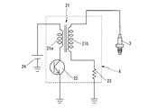
- the ignition unit 4 includes an ignition coil 21 including a primary coil 21a and a secondary coil 21b, and an igniter 22 that controls energization / interruption of a primary current to the primary coil 21a of the ignition coil 21.
- the in-vehicle battery 24 is connected to the primary coil 21a of the ignition coil 21, and the ignition plug 3 is connected to the secondary coil 21b.
- the resistance 23 for secondary current detection is provided in series with the secondary coil 21b. A signal indicating the secondary current of each cylinder detected through the secondary current detection resistor 23 is input to the engine controller 10 and monitored by the engine controller 10.
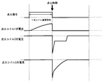
- FIG. 3 shows the operation of the ignition unit 4 using the ignition coil 21 as described above.
- a primary current is supplied to the primary coil 21 a of the ignition coil 21 through the igniter 22 for an appropriate energization time.
- This primary current is interrupted at a predetermined ignition timing.
- a high discharge voltage (secondary voltage) is generated in the secondary coil 21b, and discharge occurs between the electrodes of the spark plug 3 with dielectric breakdown of the air-fuel mixture.
- a very high voltage capacitive discharge occurs instantaneously, followed by an induction discharge.
- the secondary current flowing between the electrodes decreases relatively abruptly in a triangular wave shape with the passage of time from the start of the discharge.
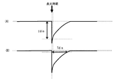
- the in-cylinder pressure is estimated based on the substantial peak value of the secondary current. That is, as shown in FIG. 4A, the engine controller 10 reads the current value Idis of the secondary current immediately after the end of the capacity discharge as a substantial peak value. For example, the current value Idis when a very short predetermined time has elapsed from the ignition timing is detected. This is because the current value at the time of capacitive discharge showing a very high voltage in an extremely short time is considered to be relatively unstable and difficult to detect accurately.
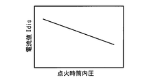
- the current value (substantial peak value) of the secondary current detected as shown in FIG. 4A is equal to the in-cylinder pressure (gas pressure between the electrodes) at the ignition timing.
- both have a characteristic that the current value decreases as the in-cylinder pressure increases, and has a linear relationship, for example.
- the relationship between the two hardly changes even if the engine rotational speed, the strength of gas flow, or the like changes. Therefore, the in-cylinder pressure at the ignition timing can be uniquely estimated based on the current value Idis of the secondary current immediately after the end of the capacity discharge.
- the in-cylinder pressure at the ignition timing estimated in this way can be used for various controls. For example, detection of a change over time in the mechanical compression ratio due to deposit accumulation and detection of variation in the compression ratio of each cylinder. It is possible to apply to.
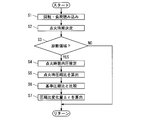
- FIG. 6 is a flowchart showing a specific processing flow of the first embodiment in which the estimation of the in-cylinder pressure is used for estimation of a change with time of the mechanical compression ratio. The process shown in this flowchart is executed in the engine controller 10 every time each cylinder is ignited, for example.
- step 1 the rotational speed and load of the internal combustion engine 1 are read, and in step 2, the ignition timing is determined.
- step 3 it is determined whether or not the operating condition is to perform a diagnosis of the temporal change of the mechanical compression ratio.
- FIG. 7 is an explanatory diagram illustrating the diagnosis region with the horizontal axis as the ignition timing and the vertical axis as the intake pressure as the operating conditions of the internal combustion engine 1.
- the compression ratio change with time is diagnosed in a predetermined diagnostic region where the intake pressure is high and the ignition timing is near top dead center.
- This diagnostic region generally corresponds to the low speed full load region of the internal combustion engine 1.
- the diagnosis is not limited to the steady operation, and the diagnosis may be performed when the ignition timing is retarded near the top dead center (in the diagnosis region) for some reason.
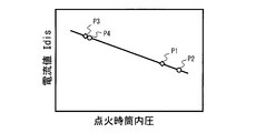
- FIG. 8 is an explanatory diagram for explaining this. For example, assuming that the P1 point is initially set under an operation condition in which the in-cylinder pressure at the ignition timing is relatively high, a certain mechanical compression ratio with time is given. When there is a change, the in-cylinder pressure changes at point P2. Between the P1 point and the P2 point, a change in the in-cylinder pressure and, in turn, a change in the current value Idis is relatively large.
- step 4 the in-cylinder pressure Pign at the ignition timing is estimated based on the current value Idis according to the characteristics shown in FIG. For example, a corresponding value is retrieved from a table created along the characteristics shown in FIG.
- Step 5 based on the in-cylinder pressure Pign at the ignition timing, a compression ratio ⁇ sign (mechanical compression ratio) at the ignition timing is calculated.
- the in-cylinder pressure Pign at the ignition timing has the relationship of the following equation (1) with respect to the intake pressure P1, the compression ratio ⁇ sign and the specific heat ratio ⁇ at the ignition timing.
- ⁇ sign exp ⁇ ln (Pign / P1) / ⁇ (2)
- the intake pressure P1 and the specific heat ratio ⁇ can be obtained, for example, with reference to a map or table created in advance using the engine speed and load or the ignition timing as parameters.
- the intake pressure P1 can be detected directly by providing an intake pressure sensor in the intake collector 8.
- step 6 the compression ratio ⁇ sign at the estimated ignition timing is compared with the original reference compression ratio (reference mechanical compression ratio at the same ignition timing).
- the reference compression ratio is searched from a table created in advance using the ignition timing as a parameter.
- the piston position may be obtained from the ignition timing, and the reference compression ratio corresponding to each ignition timing may be calculated based on the piston position.
- Step 6 since the amount of change over time of the compression ratio at the ignition timing is obtained, finally, in Step 7, the mechanical compression ratio at the piston top dead center position, which is generally expressed as “mechanical compression ratio”. It is converted into a change amount ⁇ of ⁇ .
- the compression ratio change ⁇ over time of a certain cylinder can be obtained, and by sequentially performing this, the change over time in the compression ratio of each cylinder can be obtained.
- the in-cylinder pressure at the ignition timing is estimated based on the discharge time during which the secondary current flows and the engine speed. That is, as shown in FIG. 4B, the engine controller 10 reads a time during which a secondary current having a predetermined threshold value or more flows as a discharge time Tdis.
- the threshold value is set to an appropriate value so as to avoid erroneous detection, but may be a very small value close to 0.
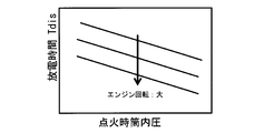
- the discharge time Tdis detected as shown in FIG. 4B correlates with the in-cylinder pressure (gas pressure between the electrodes) at the ignition timing.
- both have a characteristic that the discharge time becomes shorter as the in-cylinder pressure becomes higher, and has a linear relationship, for example.
- the relationship between the two hardly changes even if the strength of the gas flow other than the engine speed changes. Accordingly, it is possible to uniquely estimate the in-cylinder pressure at the ignition timing based on the discharge time Tdis and the engine speed.
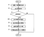
- FIG. 10 is a flowchart showing a specific processing flow of the second embodiment in which the estimation of the in-cylinder pressure is used for estimation of the change over time of the mechanical compression ratio. The process shown in this flowchart is executed in the engine controller 10 every time each cylinder is ignited, for example.
- Steps 1 to 3 and 5 to 7 are substantially the same as the steps in the flowchart of FIG. 6 described above.
- Step 1 the rotational speed and load of the internal combustion engine 1 are read, and in Step 2, the ignition timing is determined. To do.
- step 3 it is determined whether or not the operating condition is to perform a diagnosis of a change with time of the mechanical compression ratio. If it is not the diagnosis area shown in FIG. 7, the routine is terminated, and if it is the diagnosis area, the process proceeds to Step 4A.
- step 4A the in-cylinder pressure Pign at the ignition timing is estimated based on the discharge time Tdis and the engine rotation speed in accordance with the characteristics shown in FIG. For example, a corresponding value is retrieved from a three-dimensional map created along the characteristics shown in FIG.
- step 5 the compression ratio ⁇ ign at the ignition timing is calculated based on the in-cylinder pressure Pign at the ignition timing. This is as described above.
- step 6 the estimated compression ratio ⁇ sign at the ignition timing is compared with the original reference compression ratio (reference mechanical compression ratio at the same ignition timing).
- step 7 the piston top dead center position is determined. The amount of change ⁇ of the mechanical compression ratio ⁇ at is obtained.
- the time-dependent compression ratio change amount ⁇ of one cylinder can be obtained as in the first embodiment, and the change over time of each cylinder can be obtained by sequentially performing this process. Can do.
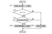
- FIG. 11 is a flowchart showing an example of processing executed for a change in compression ratio with time obtained by the first embodiment or the second embodiment. This example of FIG. 11 is possible to prevent pre-ignition and knocking when a change in mechanical compression ratio over time (specifically, an increase in mechanical compression ratio) occurs due to deposit accumulation or the like.
- the effective compression ratio is made lower than the normal set value via the variable valve device 6.
- step 11 the amount of change ⁇ over time of the mechanical compression ratio is obtained by the method of the first embodiment or the second embodiment described above.
- step 12 it is determined whether or not the compression ratio change amount ⁇ over time is larger than a predetermined threshold value ⁇ (that is, an allowable value).
- a predetermined threshold value ⁇ that is, an allowable value.
- the routine proceeds to step 13, where it is determined whether or not a predetermined low speed and high load region in which abnormal combustion such as pre-ignition or knocking is likely to occur. If “YES” here, the process proceeds to a step 14, and the intake valve closing timing located after the bottom dead center is corrected through the variable valve device 6 to retard the effective compression ratio from the normal set value. If NO in step 12 or step 13, the process proceeds to step 15 and the intake valve closing timing is controlled as usual.
- the intake valve closing timing delay correction corresponding to the compression ratio change amount ⁇ may be performed for each cylinder. it can. Further, when the intake valve closing timing is changed at the same time for all cylinders, for example, in step 12, the average value of the compression ratio change ⁇ of all cylinders or the compression ratio change amount ⁇ of each cylinder The maximum value may be compared with the allowable value (threshold value ⁇ ).
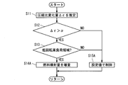
- FIG. 12 is a flowchart showing an example of processing executed for a change in compression ratio with time obtained by the first embodiment or the second embodiment.
- a change in mechanical compression ratio over time due to deposit accumulation or the like specifically, an increase in the mechanical compression ratio
- the pre-ignition or knocking is suppressed.
- the fuel injection amount of the cylinder is increased.
- Steps 11 to 13 are the same as the respective steps in FIG. 11.
- the amount of change ⁇ over time in the mechanical compression ratio is obtained by the method of the first embodiment or the second embodiment described above.
- a predetermined threshold value ⁇ that is, an allowable value.
- the routine proceeds to step 13, where it is determined whether or not a predetermined low speed and high load region in which abnormal combustion such as pre-ignition or knocking is likely to occur. If “YES" here, the process proceeds to a step 14A to increase and correct the fuel injection amount from the fuel injection valve 2. If NO in step 12 or step 13, the process proceeds to step 15A to control the fuel injection amount as usual.
- the fuel injection amount increase correction may be performed only for the cylinders whose compression ratio change amount ⁇ exceeds the threshold value ⁇ , but the fuel increase is performed for all the cylinders at the same time. Also good.
- the combustion temperature is positively increased for incineration removal of deposits accumulated in the cylinder.
- the deposited combustion operation may be executed.
- the detection of the in-cylinder pressure at the ignition timing is applied to the detection of the change over time of the mechanical compression ratio, but the cylinder in the multi-cylinder internal combustion engine is detected by using the detection of the in-cylinder pressure at the ignition timing. It is also possible to detect the compression ratio variation. That is, by individually detecting the in-cylinder pressure at the ignition timing of each cylinder during operation of the internal combustion engine, it is possible to easily detect the compression ratio variation between the cylinders, and in consideration of this compression ratio variation, Correction of the cylinder fuel injection amount and fuel injection timing, correction of ignition timing, and the like can be performed.
Landscapes
- Engineering & Computer Science (AREA)
- Chemical & Material Sciences (AREA)
- Combustion & Propulsion (AREA)
- Mechanical Engineering (AREA)
- General Engineering & Computer Science (AREA)
- Combined Controls Of Internal Combustion Engines (AREA)
- Ignition Installations For Internal Combustion Engines (AREA)
- Electrical Control Of Ignition Timing (AREA)
Abstract
Description
上記電極間に流れる二次電流をモニタする二次電流検知手段と、
この二次電流に基づいて点火時期における筒内圧を推定する筒内圧推定手段と、
を備えている。
上記電極間に流れる二次電流をモニタし、
この二次電流に基づいて点火時期における筒内圧を推定する、
ものである。
従って、点火時期における圧縮比εignは、次の(2)式から求まる。
ここで、吸気圧P1および比熱比κは、例えば、機関回転速度と負荷、あるいは点火時期をパラメータとして予め作成したマップないしテーブルを参照して求めることができる。吸気圧P1については、吸気コレクタ8に吸気圧センサを設けて直接検出することも可能である。
Claims (10)
- 点火コイルの一次コイルに一次電流を通電しかつ遮断することで、二次コイルに接続された点火プラグの電極間に放電電圧を発生させる内燃機関の点火装置において、
上記電極間に流れる二次電流をモニタする二次電流検知手段と、
この二次電流に基づいて点火時期における筒内圧を推定する筒内圧推定手段と、
を備えてなる内燃機関の点火装置。 - 上記筒内圧推定手段は、容量放電終了直後の二次電流の電流値に基づいて点火時期における筒内圧を推定する、請求項1に記載の内燃機関の点火装置。
- 容量放電終了直後の二次電流の電流値として、点火時期から所定時間経過した時点の電流値を用いる、請求項2に記載の内燃機関の点火装置。
- 上記筒内圧推定手段は、二次電流が流れる放電時間と機関回転速度とに基づいて点火時期における筒内圧を推定する、請求項1に記載の内燃機関の点火装置。
- 所定の閾値以上の電流が流れる時間を上記放電時間として検出する、請求項4に記載の内燃機関の点火装置。
- 推定した筒内圧に基づいて当該気筒の点火時期における圧縮比を求める圧縮比推定手段をさらに備える、請求項1~5のいずれかに記載の内燃機関の点火装置。
- 上記圧縮比を、点火時期に対応した基準圧縮比と比較する圧縮比診断手段をさらに備える、請求項6に記載の内燃機関の点火装置。
- 多気筒内燃機関において各気筒毎に筒内圧の推定を行い、各気筒の筒内圧のばらつきを求める、請求項1~7のいずれかに記載の内燃機関の点火装置。
- 吸気圧が高くかつ点火時期が上死点近傍となる内燃機関の特定の運転条件下で筒内圧の推定を行う、請求項1~8のいずれかに記載の内燃機関の点火装置。
- 点火コイルの一次コイルに一次電流を通電しかつ遮断することで、二次コイルに接続された点火プラグの電極間に放電電圧を発生させる内燃機関の点火方法において、
上記電極間に流れる二次電流をモニタし、
この二次電流に基づいて点火時期における筒内圧を推定する、
内燃機関の点火方法。
Priority Applications (5)
| Application Number | Priority Date | Filing Date | Title |
|---|---|---|---|
| CN201480075764.5A CN106030099B (zh) | 2014-02-17 | 2014-02-17 | 内燃机的点火装置以及点火方法 |
| PCT/JP2014/053601 WO2015122004A1 (ja) | 2014-02-17 | 2014-02-17 | 内燃機関の点火装置および点火方法 |
| JP2015562669A JP6090481B2 (ja) | 2014-02-17 | 2014-02-17 | 内燃機関の点火装置および点火方法 |
| US15/116,667 US10519879B2 (en) | 2014-02-17 | 2014-02-17 | Determining in-cylinder pressure by analyzing current of a spark plug |
| EP14882294.3A EP3109457B1 (en) | 2014-02-17 | 2014-02-17 | Ignition device and ignition method for internal combustion engine |
Applications Claiming Priority (1)
| Application Number | Priority Date | Filing Date | Title |
|---|---|---|---|
| PCT/JP2014/053601 WO2015122004A1 (ja) | 2014-02-17 | 2014-02-17 | 内燃機関の点火装置および点火方法 |
Publications (1)
| Publication Number | Publication Date |
|---|---|
| WO2015122004A1 true WO2015122004A1 (ja) | 2015-08-20 |
Family
ID=53799767
Family Applications (1)
| Application Number | Title | Priority Date | Filing Date |
|---|---|---|---|
| PCT/JP2014/053601 Ceased WO2015122004A1 (ja) | 2014-02-17 | 2014-02-17 | 内燃機関の点火装置および点火方法 |
Country Status (5)
| Country | Link |
|---|---|
| US (1) | US10519879B2 (ja) |
| EP (1) | EP3109457B1 (ja) |
| JP (1) | JP6090481B2 (ja) |
| CN (1) | CN106030099B (ja) |
| WO (1) | WO2015122004A1 (ja) |
Cited By (2)
| Publication number | Priority date | Publication date | Assignee | Title |
|---|---|---|---|---|
| JP2016094854A (ja) * | 2014-11-13 | 2016-05-26 | 日立オートモティブシステムズ株式会社 | 内燃機関の制御装置 |
| JP2018066305A (ja) * | 2016-10-18 | 2018-04-26 | 株式会社エッチ・ケー・エス | 内燃機関用点火装置 |
Families Citing this family (2)
| Publication number | Priority date | Publication date | Assignee | Title |
|---|---|---|---|---|
| JP7101460B2 (ja) * | 2017-05-10 | 2022-07-15 | 日立Astemo株式会社 | 内燃機関の制御装置 |
| JP7324384B2 (ja) * | 2021-02-24 | 2023-08-09 | 日立Astemo株式会社 | 筒内圧力検出方法、筒内圧センサ診断方法及び内燃機関制御装置 |
Citations (3)
| Publication number | Priority date | Publication date | Assignee | Title |
|---|---|---|---|---|
| JPS57194043U (ja) * | 1981-05-19 | 1982-12-09 | ||
| JPH07198545A (ja) * | 1993-11-08 | 1995-08-01 | Chrysler Corp | 火花放電点火内燃機関の燃焼シリンダにおける負荷を決定する方法 |
| JP2001020805A (ja) * | 1999-07-06 | 2001-01-23 | Honda Motor Co Ltd | 内燃機関制御装置 |
Family Cites Families (14)
| Publication number | Priority date | Publication date | Assignee | Title |
|---|---|---|---|---|
| DE3234629A1 (de) * | 1982-09-18 | 1984-03-22 | Robert Bosch Gmbh, 7000 Stuttgart | Einrichtung zum erfassen von druckschwankungen im brennraum einer brennkraftmaschine |
| JP2592075B2 (ja) * | 1987-10-19 | 1997-03-19 | 日産自動車株式会社 | 可変圧縮比型内燃機関の制御装置 |
| US4836015A (en) * | 1988-06-14 | 1989-06-06 | General Motors Corporation | Method and apparatus for determining the compression ratio of an engine cylinder |
| JP2705041B2 (ja) | 1991-03-12 | 1998-01-26 | 本田技研工業株式会社 | 内燃機関の失火検出装置 |
| JPH10196507A (ja) * | 1997-01-09 | 1998-07-31 | Nippon Soken Inc | 燃焼状態検出装置 |
| JP2000034969A (ja) * | 1998-07-15 | 2000-02-02 | Ngk Spark Plug Co Ltd | スパークプラグを用いた燃焼状態検出装置 |
| DE10201164A1 (de) * | 2002-01-15 | 2003-08-14 | Bosch Gmbh Robert | Verfahren und Vorrichtung zur Erkennung einer Phase eines Viertakt-Ottomotors |
| JP2005048621A (ja) * | 2003-07-31 | 2005-02-24 | Toyota Motor Corp | 内燃機関の圧縮比算出装置、圧縮比算出方法、内燃機関の制御装置およびその制御方法 |
| JP4397804B2 (ja) * | 2004-12-27 | 2010-01-13 | 本田技研工業株式会社 | ノッキング検出装置 |
| JP2011220309A (ja) * | 2010-04-14 | 2011-11-04 | Toyota Motor Corp | 点火プラグの磨耗量推定装置、内燃機関の制御装置 |
| JP5392241B2 (ja) | 2010-12-03 | 2014-01-22 | 三菱自動車工業株式会社 | 多気筒内燃機関 |
| JP5983740B2 (ja) * | 2012-05-14 | 2016-09-06 | トヨタ自動車株式会社 | 内燃機関の制御装置 |
| WO2016063430A1 (ja) * | 2014-10-24 | 2016-04-28 | 日立オートモティブシステムズ阪神株式会社 | 内燃機関用失火検出方法 |
| JP6302822B2 (ja) * | 2014-11-13 | 2018-03-28 | 日立オートモティブシステムズ株式会社 | 内燃機関の制御装置 |
-
2014
- 2014-02-17 JP JP2015562669A patent/JP6090481B2/ja not_active Expired - Fee Related
- 2014-02-17 CN CN201480075764.5A patent/CN106030099B/zh not_active Expired - Fee Related
- 2014-02-17 WO PCT/JP2014/053601 patent/WO2015122004A1/ja not_active Ceased
- 2014-02-17 EP EP14882294.3A patent/EP3109457B1/en not_active Not-in-force
- 2014-02-17 US US15/116,667 patent/US10519879B2/en not_active Expired - Fee Related
Patent Citations (3)
| Publication number | Priority date | Publication date | Assignee | Title |
|---|---|---|---|---|
| JPS57194043U (ja) * | 1981-05-19 | 1982-12-09 | ||
| JPH07198545A (ja) * | 1993-11-08 | 1995-08-01 | Chrysler Corp | 火花放電点火内燃機関の燃焼シリンダにおける負荷を決定する方法 |
| JP2001020805A (ja) * | 1999-07-06 | 2001-01-23 | Honda Motor Co Ltd | 内燃機関制御装置 |
Cited By (2)
| Publication number | Priority date | Publication date | Assignee | Title |
|---|---|---|---|---|
| JP2016094854A (ja) * | 2014-11-13 | 2016-05-26 | 日立オートモティブシステムズ株式会社 | 内燃機関の制御装置 |
| JP2018066305A (ja) * | 2016-10-18 | 2018-04-26 | 株式会社エッチ・ケー・エス | 内燃機関用点火装置 |
Also Published As
| Publication number | Publication date |
|---|---|
| EP3109457B1 (en) | 2018-06-20 |
| CN106030099B (zh) | 2018-12-04 |
| JPWO2015122004A1 (ja) | 2017-03-30 |
| EP3109457A1 (en) | 2016-12-28 |
| US20160348596A1 (en) | 2016-12-01 |
| CN106030099A (zh) | 2016-10-12 |
| EP3109457A4 (en) | 2017-03-15 |
| JP6090481B2 (ja) | 2017-03-08 |
| US10519879B2 (en) | 2019-12-31 |
Similar Documents
| Publication | Publication Date | Title |
|---|---|---|
| US9683535B2 (en) | Method and system for detection of hot spark plug fouling | |
| US9534984B2 (en) | Spark plug fouling detection for ignition system | |
| US9618422B2 (en) | Spark plug fouling detection | |
| CN103306837B (zh) | 用于阻止燃料空气混合物在内燃机气缸室中预燃的方法 | |
| US9068522B2 (en) | Method for diagnosing an engine | |
| CN106401776B (zh) | 用于点火控制的方法和系统 | |
| JP6357985B2 (ja) | 内燃機関の点火装置および点火方法 | |
| JP6090481B2 (ja) | 内燃機関の点火装置および点火方法 | |
| US8924134B2 (en) | Knock control device of internal combustion engine | |
| JP6350135B2 (ja) | 内燃機関の点火装置および点火方法 | |
| US20160215749A1 (en) | Control device of internal combustion engine | |
| JP4799646B2 (ja) | 内燃機関の異常着火制御装置 | |
| JP2013104371A (ja) | 内燃機関の制御装置 | |
| JP6022594B2 (ja) | エンジン制御システム | |
| WO2021106520A1 (ja) | 内燃機関用制御装置 | |
| JP2012219757A (ja) | 内燃機関の制御装置 | |
| JP2022146773A (ja) | 内燃機関の制御装置 | |
| JP2018172994A (ja) | 内燃機関制御装置 | |
| JP7247364B2 (ja) | 内燃機関用制御装置 | |
| JP2016056684A (ja) | エンジン制御装置 | |
| JP2013104323A (ja) | 内燃機関の制御装置 | |
| JP5896839B2 (ja) | 内燃機関の制御装置 | |
| JP5911342B2 (ja) | 内燃機関の燃焼状態判定装置 | |
| JP2010127103A (ja) | 内燃機関の制御装置 | |
| JP2016109100A (ja) | 内燃機関の診断装置 |
Legal Events
| Date | Code | Title | Description |
|---|---|---|---|
| 121 | Ep: the epo has been informed by wipo that ep was designated in this application |
Ref document number: 14882294 Country of ref document: EP Kind code of ref document: A1 |
|
| ENP | Entry into the national phase |
Ref document number: 2015562669 Country of ref document: JP Kind code of ref document: A |
|
| WWE | Wipo information: entry into national phase |
Ref document number: 15116667 Country of ref document: US |
|
| NENP | Non-entry into the national phase |
Ref country code: DE |
|
| REEP | Request for entry into the european phase |
Ref document number: 2014882294 Country of ref document: EP |
|
| WWE | Wipo information: entry into national phase |
Ref document number: 2014882294 Country of ref document: EP |