WO2015122196A1 - Dispositif de détermination d'état d'occupation, système de distribution, procédé de détermination d'état d'occupation, programme de détermination d'état d'occupation et terminal de distribution - Google Patents
Dispositif de détermination d'état d'occupation, système de distribution, procédé de détermination d'état d'occupation, programme de détermination d'état d'occupation et terminal de distribution Download PDFInfo
- Publication number
- WO2015122196A1 WO2015122196A1 PCT/JP2015/000672 JP2015000672W WO2015122196A1 WO 2015122196 A1 WO2015122196 A1 WO 2015122196A1 JP 2015000672 W JP2015000672 W JP 2015000672W WO 2015122196 A1 WO2015122196 A1 WO 2015122196A1
- Authority
- WO
- WIPO (PCT)
- Prior art keywords
- home
- power
- discharge
- status
- charge
- Prior art date
- Legal status (The legal status is an assumption and is not a legal conclusion. Google has not performed a legal analysis and makes no representation as to the accuracy of the status listed.)
- Ceased
Links
Images





Classifications
-
- H—ELECTRICITY
- H02—GENERATION; CONVERSION OR DISTRIBUTION OF ELECTRIC POWER
- H02J—ELECTRIC POWER NETWORKS; CIRCUIT ARRANGEMENTS OR SYSTEMS FOR SUPPLYING OR DISTRIBUTING ELECTRIC POWER; SYSTEMS FOR STORING ELECTRIC ENERGY
- H02J3/00—Circuit arrangements for AC mains or AC distribution networks
- H02J3/28—Arrangements for balancing of the load in networks by storage of energy
- H02J3/32—Arrangements for balancing of the load in networks by storage of energy using batteries or super capacitors with converting means
-
- G—PHYSICS
- G01—MEASURING; TESTING
- G01R—MEASURING ELECTRIC VARIABLES; MEASURING MAGNETIC VARIABLES
- G01R31/00—Arrangements for testing electric properties; Arrangements for locating electric faults; Arrangements for electrical testing characterised by what is being tested not provided for elsewhere
- G01R31/36—Arrangements for testing, measuring or monitoring the electrical condition of accumulators or electric batteries, e.g. capacity or state of charge [SoC]
- G01R31/382—Arrangements for monitoring battery or accumulator variables, e.g. SoC
-
- G—PHYSICS
- G01—MEASURING; TESTING
- G01V—GEOPHYSICS; GRAVITATIONAL MEASUREMENTS; DETECTING MASSES OR OBJECTS; TAGS
- G01V3/00—Electric or magnetic prospecting or detecting; Measuring magnetic field characteristics of the earth, e.g. declination, deviation
- G01V3/02—Electric or magnetic prospecting or detecting; Measuring magnetic field characteristics of the earth, e.g. declination, deviation operating with propagation of electric current
- G01V3/04—Electric or magnetic prospecting or detecting; Measuring magnetic field characteristics of the earth, e.g. declination, deviation operating with propagation of electric current using DC
-
- G—PHYSICS
- G01—MEASURING; TESTING
- G01V—GEOPHYSICS; GRAVITATIONAL MEASUREMENTS; DETECTING MASSES OR OBJECTS; TAGS
- G01V3/00—Electric or magnetic prospecting or detecting; Measuring magnetic field characteristics of the earth, e.g. declination, deviation
- G01V3/38—Processing data, e.g. for analysis, for interpretation, for correction
-
- G—PHYSICS
- G05—CONTROLLING; REGULATING
- G05B—CONTROL OR REGULATING SYSTEMS IN GENERAL; FUNCTIONAL ELEMENTS OF SUCH SYSTEMS; MONITORING OR TESTING ARRANGEMENTS FOR SUCH SYSTEMS OR ELEMENTS
- G05B15/00—Systems controlled by a computer
- G05B15/02—Systems controlled by a computer electric
-
- G—PHYSICS
- G06—COMPUTING OR CALCULATING; COUNTING
- G06Q—INFORMATION AND COMMUNICATION TECHNOLOGY [ICT] SPECIALLY ADAPTED FOR ADMINISTRATIVE, COMMERCIAL, FINANCIAL, MANAGERIAL OR SUPERVISORY PURPOSES; SYSTEMS OR METHODS SPECIALLY ADAPTED FOR ADMINISTRATIVE, COMMERCIAL, FINANCIAL, MANAGERIAL OR SUPERVISORY PURPOSES, NOT OTHERWISE PROVIDED FOR
- G06Q10/00—Administration; Management
- G06Q10/04—Forecasting or optimisation specially adapted for administrative or management purposes, e.g. linear programming or "cutting stock problem"
-
- G—PHYSICS
- G06—COMPUTING OR CALCULATING; COUNTING
- G06Q—INFORMATION AND COMMUNICATION TECHNOLOGY [ICT] SPECIALLY ADAPTED FOR ADMINISTRATIVE, COMMERCIAL, FINANCIAL, MANAGERIAL OR SUPERVISORY PURPOSES; SYSTEMS OR METHODS SPECIALLY ADAPTED FOR ADMINISTRATIVE, COMMERCIAL, FINANCIAL, MANAGERIAL OR SUPERVISORY PURPOSES, NOT OTHERWISE PROVIDED FOR
- G06Q10/00—Administration; Management
- G06Q10/08—Logistics, e.g. warehousing, loading or distribution; Inventory or stock management
-
- G—PHYSICS
- G06—COMPUTING OR CALCULATING; COUNTING
- G06Q—INFORMATION AND COMMUNICATION TECHNOLOGY [ICT] SPECIALLY ADAPTED FOR ADMINISTRATIVE, COMMERCIAL, FINANCIAL, MANAGERIAL OR SUPERVISORY PURPOSES; SYSTEMS OR METHODS SPECIALLY ADAPTED FOR ADMINISTRATIVE, COMMERCIAL, FINANCIAL, MANAGERIAL OR SUPERVISORY PURPOSES, NOT OTHERWISE PROVIDED FOR
- G06Q50/00—Information and communication technology [ICT] specially adapted for implementation of business processes of specific business sectors, e.g. utilities or tourism
- G06Q50/06—Energy or water supply
-
- H—ELECTRICITY
- H02—GENERATION; CONVERSION OR DISTRIBUTION OF ELECTRIC POWER
- H02J—ELECTRIC POWER NETWORKS; CIRCUIT ARRANGEMENTS OR SYSTEMS FOR SUPPLYING OR DISTRIBUTING ELECTRIC POWER; SYSTEMS FOR STORING ELECTRIC ENERGY
- H02J3/00—Circuit arrangements for AC mains or AC distribution networks
- H02J3/008—Circuit arrangements for power supply or distribution technologies responsive to energy trading
-
- H—ELECTRICITY
- H02—GENERATION; CONVERSION OR DISTRIBUTION OF ELECTRIC POWER
- H02J—ELECTRIC POWER NETWORKS; CIRCUIT ARRANGEMENTS OR SYSTEMS FOR SUPPLYING OR DISTRIBUTING ELECTRIC POWER; SYSTEMS FOR STORING ELECTRIC ENERGY
- H02J7/00—Circuit arrangements for charging or discharging batteries or for supplying loads from batteries
- H02J7/80—Circuit arrangements for charging or discharging batteries or for supplying loads from batteries including monitoring or indicating arrangements
- H02J7/82—Control of state of charge [SOC]
-
- Y—GENERAL TAGGING OF NEW TECHNOLOGICAL DEVELOPMENTS; GENERAL TAGGING OF CROSS-SECTIONAL TECHNOLOGIES SPANNING OVER SEVERAL SECTIONS OF THE IPC; TECHNICAL SUBJECTS COVERED BY FORMER USPC CROSS-REFERENCE ART COLLECTIONS [XRACs] AND DIGESTS
- Y04—INFORMATION OR COMMUNICATION TECHNOLOGIES HAVING AN IMPACT ON OTHER TECHNOLOGY AREAS
- Y04S—SYSTEMS INTEGRATING TECHNOLOGIES RELATED TO POWER NETWORK OPERATION, COMMUNICATION OR INFORMATION TECHNOLOGIES FOR IMPROVING THE ELECTRICAL POWER GENERATION, TRANSMISSION, DISTRIBUTION, MANAGEMENT OR USAGE, i.e. SMART GRIDS
- Y04S10/00—Systems supporting electrical power generation, transmission or distribution
- Y04S10/50—Systems or methods supporting the power network operation or management, involving a certain degree of interaction with the load-side end user applications
-
- Y—GENERAL TAGGING OF NEW TECHNOLOGICAL DEVELOPMENTS; GENERAL TAGGING OF CROSS-SECTIONAL TECHNOLOGIES SPANNING OVER SEVERAL SECTIONS OF THE IPC; TECHNICAL SUBJECTS COVERED BY FORMER USPC CROSS-REFERENCE ART COLLECTIONS [XRACs] AND DIGESTS
- Y04—INFORMATION OR COMMUNICATION TECHNOLOGIES HAVING AN IMPACT ON OTHER TECHNOLOGY AREAS
- Y04S—SYSTEMS INTEGRATING TECHNOLOGIES RELATED TO POWER NETWORK OPERATION, COMMUNICATION OR INFORMATION TECHNOLOGIES FOR IMPROVING THE ELECTRICAL POWER GENERATION, TRANSMISSION, DISTRIBUTION, MANAGEMENT OR USAGE, i.e. SMART GRIDS
- Y04S50/00—Market activities related to the operation of systems integrating technologies related to power network operation or related to communication or information technologies
- Y04S50/10—Energy trading, including energy flowing from end-user application to grid
Definitions
- the present invention relates to a home status determination device, a delivery system, a home status determination method, a home status determination program, and a delivery terminal.
- Patent Document 1 discloses a system that calculates a home probability using information on power consumption by automatic meter reading.
- the at-home probability calculation system of Patent Document 1 determines the at-home situation based on the amount of power used and the amount of change detected by the automatic meter reading system. Further, after taking into account the behavioral characteristics of each home based on the past power usage information, this power usage information is processed into a “home probability” at a designated future time. More preferably, the “home probability” is provided to the service user, and the service user can make a visit schedule to the user's home using the “home probability” as a criterion.
- a home situation is determined based on the electric power consumption (usage of the purchased electric power supplied from a system
- the accuracy is not sufficient to determine the home status based on the power consumption detected by the automatic meter reading system.
- a power storage device is installed in a house or the like. The power storage device charges the storage battery with power supplied from the grid and discharges when power is required. Utilizing this function, the power storage device is used for the purpose of leveling the backup power source and power consumption during a power failure. The leveling of power usage is to reduce the peak value of power usage by charging the battery with power from the grid at night and discharging it from the storage battery at the peak of daytime power demand.
- the power usage detected by the automatic meter-reading system is leveled throughout the day and the amount of change is reduced. Therefore, it is difficult to determine the home status based on the amount of power used or the amount of change.
- An object of the present invention is to provide a home status determination device, a delivery system, a home status determination method, a home status determination program, and a delivery terminal that solve the above-described problems and accurately determine the home status.
- the present invention relates to charging / discharging information acquisition means for acquiring charging / discharging information indicating a charging status or a discharging status of a power storage device that supplies electric power to a load provided in a home, and determines the home status of the home based on the charging / discharging information
- a home status determination device including a home status determination means.
- a delivery system includes a power storage unit that supplies power to a load provided in a house that is a delivery destination, a charge / discharge information acquisition unit that acquires charge / discharge information indicating a charge status or a discharge status of the power storage unit, Home status determining means for determining the home status of the house based on the discharge information, and means for outputting a delivery route including the house whose home status is determined to be home.
- the present invention is a home status determination method for acquiring charge / discharge information indicating a charge status or a discharge status of a power storage device that supplies power to a load provided in a home and determining the home status of the home based on the charge / discharge information. .
- the recording medium on which the home status determination program of the present invention is recorded is a recording medium recording a program that causes a computer to function as a home status determination device for determining the home status of a house, and supplies power to a load provided in the house
- a recording medium recording a home status determination program for executing a process of acquiring charge / discharge information indicating a charge status or a discharge status of the power storage device and a process of determining the home status of the house based on the charge / discharge information is there.
- the present invention shows a charging state or a discharging state of a power storage device that supplies power to a load provided in a house, a means for transmitting a request for designating a house as a delivery destination, and a delivery time to the delivery destination.
- a delivery terminal comprising: means for receiving the home status of the house determined based on charge / discharge information; and means for outputting a delivery route including a house whose home status is determined to be home.
- the home status can be determined with high accuracy.
- FIG. 1 It is a figure which shows an example of embodiment of this invention. It is a figure which shows an example of a structure of the house 100 in embodiment of this invention. It is a figure which shows an example of the functional block of the at-home situation determination apparatus 105 in embodiment of this invention. It is a figure which shows an example of the charging / discharging information of this invention. It is a figure which shows the example of the operation
- FIG. 1 shows an example of a system to which the at-home situation determination apparatus of the present invention is applied.
- the home status determination apparatus 105 of the present invention is connected to the user's house 100 via the network 104 and the communication line 103.
- a power storage device 101 is installed in the house 100.
- the home status determination device 105 is connected to the terminal 106 via the network 104 and the communication line 103.
- the terminal 106 transmits a home status determination request designating a predetermined time (or time zone) of the house 100 to the home status determination device 105.
- the home status determination device 105 acquires charge / discharge information from the power storage device 101 of the specified home 100 under the consent of the user of the specified home, and determines the home status at the specified time.
- the home situation indicates that there is a resident in the target house 100 or no resident. Determining the home status includes determining that the home status is present, and determining that the home status is absent if the home status is not present.
- the home status determination apparatus 105 notifies the terminal 106 of the determination result of the home status.
- FIG. 2 shows an example of the house 100.
- the house 100 includes a power storage device 101, a load 306, and a power generation device 307.
- the power storage device 101 includes a storage battery 302, a BMU (Battery Management Unit) 303, a PCS (Power Condition System) 304, and a system controller 305. Then, the power storage device 101 charges the power supplied from the power system 301 and the power generation device 307 and discharges the charged power to the load 306.
- the load 306 is supplied with power from the system 301, the power storage device 101, and the power generation device 307.
- the home status determination device 105 of the present invention determines the home status of the user's house with the user's consent.
- FIG. 3 shows an example of a functional block diagram of the home status determination apparatus 105 according to the first embodiment.
- the home status determination device 105 includes charge / discharge information acquisition means 201, home status determination means 203, and storage means 202.
- the charge / discharge information acquisition unit 201 acquires charge / discharge information of the power storage device 101 from the power storage device 101.
- the charge / discharge information acquisition unit 201 transmits the charge / discharge information to the home status determination unit 203.
- the charge / discharge information is information indicating a charge state or a discharge state of the power storage device 101 (hereinafter also referred to as a charge / discharge state).
- the charging / discharging status refers to a state where the power storage device 101 is discharged to a load (excluding self-discharge), a state where the power storage device 101 is charged, a discharging power amount, a charging power amount, a discharging power, a charging power, and a change thereof. is there.
- the charge / discharge information acquisition unit 201 may transmit the charge / discharge information to the storage unit 202, and the storage unit 202 may store the charge / discharge information.
- the charge / discharge information includes the following information.
- ⁇ Information indicating that the battery is discharged -Information indicating that the battery is not in a discharged state (charge state or standby state), -The amount of power (Wh) discharged by the power storage device in the time zone divided into unit times, -The amount of power (Wh) charged by the power storage device in the time zone divided into unit times, -Electric power (W) discharged from the power storage device, -Electric power (W) charged by the power storage device,
- the time when the power storage device starts charging or discharging the load including the scheduled time to start charging or discharging, hereinafter also referred to as charge / discharge start time
- ⁇ Time when charging or discharging is completed including scheduled time, hereinafter also referred to as charging / discharging end time
- ⁇ Time that has elapsed since the charge / discharge start time ⁇ Amount of change in discharge or charge energy, ⁇ Change in discharge or charge power, ⁇ Charge / discharge schedule
- the means by which the charge / discharge information acquisition means 201 acquires charge / discharge information is not particularly limited.
- the charge / discharge information acquisition unit 201 may acquire the charge / discharge state of the power storage system from the power storage device 101 at all times.
- the charging / discharging information acquisition means 201 may acquire the charging / discharging state regularly (for example, every 30 minutes, every 3 hours).
- the charge / discharge information acquisition unit 201 may acquire the charge or discharge power amount of the power storage device 101 constantly, regularly, or irregularly.
- FIG. 4 is a diagram illustrating an example of charge / discharge information.
- the horizontal axis represents time, and the vertical axis represents the amount of power (Wh) discharged from the power storage device.
- FIG. 4 is a discharge schedule of the power storage device 101 for one day. Referring to FIG. 4, power storage device 101 is discharged at 7 to 9 o'clock and 17 to 20 o'clock.
- the notation “7-8 o'clock” shown in the figure is a time zone from 7 o'clock to 7:59 (the same applies hereinafter). However, the time zone to be divided is not limited to this, and may be, for example, every 30 minutes or 3 hours.
- a discharge start time and a discharge end time, or a time zone during which discharge is performed are set.
- a discharge power amount, a charging time zone, a charge power amount, and the like may be set.
- the storage unit 202 of the at-home situation determination apparatus 105 stores charge / discharge information. Further, the storage unit 202 stores information necessary for the home status determination unit 203 to determine the home status (for example, information indicating whether or not the user permits the determination of the home status). The storage unit 202 may be provided separately from the home status determination device 105. Here, as information indicating whether or not the user permits the determination of the home status, for example, information indicating whether or not the user permits from the power storage device 101 is input, and the home status determination device 105 includes the power storage device. The user permission information is acquired from 101.
- the information is stored in the storage unit 202, and the home status determination unit 203 reads the user permission information from the storage unit 202, and determines whether or not the user permits.
- the home status determination unit 203 determines the home status of the permitted user's home.
- the home status determination unit 203 determines the home status based on the charge / discharge information. Based on the charge / discharge information, the home status determination unit 203 determines whether the power storage system is in a discharged state. When in a discharging state, it is determined that the person is at home. Whether or not the battery is in a discharged state can be determined by a method that has been generally performed, such as measuring the value of the discharge power of the power storage device.
- the state in which the power storage device 101 supplies power to a load provided in the house is highly likely to be a state in which a load (for example, an electrical product) is used while at home. Therefore, in such a case, it is determined that the user is at home.
- the home status determination means 203 can also determine (predict) the home status at a future time. For example, the home status determination unit 203 determines whether or not it is in a discharge state at a future time according to a discharge schedule in which a discharge start time and a discharge end time of the power storage device 101 are determined. If it is in a discharged state, it is determined that the person is at home. This will be described in more detail with reference to FIG. FIG. 4 is a discharge schedule of the power storage device 101 for one day. 7 to 9 o'clock and 17 to 21 o'clock are discharge time zones. When the time for determining the home situation is 10:00, 10:00 is not included in the discharge time zone and is not in the discharge state.
- the home status determination unit 203 determines that the home status is not at 10:00.
- the time for determining the home status is 19:00, since the 19:00 is included in the discharge time zone, the home status determination unit 203 determines that the home status is at home.
- the home status determination means 203 predicts whether or not the discharge state is in the future time based on the past values of the past month, day of the week, time, season, and weather, which are the same as the future time. For example, the date and time for determining the home status is 10:00 on Monday, January 30th. Based on the discharge schedule for Mondays from December to January before January 30, for example, the home status determination unit 203 determines that the probability that 10:00 is set as the discharge time zone exceeds a certain value. It is determined that there is a high possibility that the discharge time zone is set at 10:00 on the day (month), and it is determined that the user is at home.
- the timing at which the home status determination unit 203 determines the home status is not particularly limited.
- the home status determination unit 203 may constantly monitor the charge / discharge information and determine the home status when there is a change in the charge / discharge information.
- the home status may be determined at a timing requested from the terminal, a time set in advance by a request from the terminal, or at a predetermined time interval.
- the timing and interval determined by the user may be specified.
- Home status determination means 203 determines the home status at the time specified by the request from the terminal. Alternatively, the user may determine the home situation by designating a predetermined time.
- the charge / discharge information acquisition unit 201 acquires charge / discharge information from the power storage device 101 through a communication line. Then, the charge / discharge information acquisition unit 201 transmits the charge / discharge information to the home status determination unit 203. Further, the charge / discharge information acquisition unit 201 may transmit the charge / discharge information to the storage unit 202 and store it in the storage unit 202.
- the home status determination unit 203 determines whether or not the power storage system is in a discharge state based on the charge / discharge information, and determines that the home status is in the discharge state. The home status determination unit 203 stores the determination result in the storage unit 202.
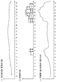
- FIG. 6A shows the amount of power used in the house 100 (the amount of purchased power supplied from the grid or power supplier).
- the horizontal axis represents time, and the vertical axis represents power consumption (Wh).
- FIG. 6B shows the amount of electric power discharged from the power storage device 101.
- FIG. 6C shows the sum of the power consumption (the amount of purchased power) in FIG. 6A and the discharge power in FIG. 6B. That is, the amount of power consumed in the house 100.
- the amount of power consumed in the house 100 increases from 7 to 9 o'clock (for example, the amount of power used increases when the user wakes up to turn on the heater or performs laundry). Then, after 9 o'clock, the amount of power decreases (for example, the amount of power used decreases when going out). After that, the amount of power increases again at 17-23 (for example, the amount of power increases by going home and turning on the heater, turning on the TV, etc.).
- the power storage device 101 discharges in a time zone in which the amount of power consumed in the house 100 is large, and operates to supplement necessary power. Then, as shown in FIG.
- the amount of power used (the amount of purchased power) is leveled by the discharge of the power storage device, and the change in the amount of power used becomes small. In such a case, it is difficult to determine the home status based on the power consumption.
- the home status is determined based on the charge / discharge information of the power storage device. Therefore, as in the above-described example, it is possible to determine the home status with higher accuracy even when the power is used while at home while suppressing the peak of power usage due to the discharge by the power storage device 101.
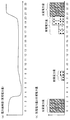
- FIG. 7 is another diagram showing the effect of this embodiment.
- FIG. 7A shows the amount of power used in the house 100 (the amount of purchased power supplied from the grid or power supplier).
- the horizontal axis represents time, and the vertical axis represents power consumption (Wh).
- FIG. 7B shows the discharge power amount (shaded bar graph) and the charge power amount (hatched bar graph) of the power storage device.
- the amount of power used (power purchased) is large at 0-3 o'clock and after 21:00. In other time periods, the power consumption is small and leveled. This is because, as shown in FIG. 7 (b), the power storage device 101 charges the power storage device 101 with power from the system during the night time period (0-3 o'clock and after 21:00) when the electricity rate is low. is there. Then, the power storage device 101 is discharged during a time period in which the electricity rate is high (including 7-9 o'clock and 17-20 o'clock), and the operation of reducing the electricity rate by suppressing the use of power from the system is performed.
- the home status cannot be correctly determined by determining the home status based on the change in the power consumption shown in FIG.
- the home status is determined using charge / discharge information.
- the 7-9 o'clock and 17-20 o'clock time zones which are the discharge time zones of the power storage device, are determined to be home.
- the at-home situation determination device 105 of the second embodiment is shown in FIG. 3 as in the first embodiment.
- the home status determination unit 203 is different from the operation of the home status determination unit 203 of the first embodiment, but the operations and functions of the other units are the same as those of the first embodiment.
- Home status determination means 203 uses the charge / discharge information to compare the amount of electric power discharged from power storage device 101 with a predetermined reference value to determine the home status. For example, if the amount of discharge power at a certain time is larger than a reference value, it is determined that the user is at home at that time.
- the reference value can be set as appropriate.
- the reference value may be a value that is 50% of the average value of the discharge power amount for each unit time zone based on the history of the discharge power amount for each unit time zone in a certain period.
- a value of 50% of the average value of the discharge power amount in the same time period in the past fixed period, or a value of 70% of the average value of the discharge power amount in the same time period on the same day of the week in the past fixed period can be used.
- an appropriate value that reflects the amount of discharge electric power that changes according to the lifestyle pattern and season can be set as the reference value, and the accuracy of home status determination can be further increased.
- the past fixed period can be variously set such as two weeks or one month.
- the reference value can be appropriately set by the user using the power storage device 101. For example, it is possible to select a load to be used at home, and to set a reference value for the amount of discharge power based on the amount of discharge power to that load. It is also possible to select a load that is always used in the absence, set a reference value for the amount of discharge power based on the total amount of discharge power to those loads, and determine that the load is absent if it is below that reference value. it can.
- the home status determination unit 203 may determine the home status according to the amount of change in the discharge power amount of the power storage device based on the charge / discharge information. For example, when the amount of change in the amount of discharge power exceeds a reference value, it can be determined that the user is at home or absent. When returning to the house 100 or going out of the house 100, it is conceivable that the amount of discharged power changes greatly. For example, when the discharge power amount exceeds a certain reference value, it can be determined that the user is at home. Alternatively, it may be determined that the user is at home at a time later than the time when the amount of discharge electric power increases and while a discharge exceeding a certain value is being performed.
- the reference value in this case can be set as appropriate, such as the amount of change in the past discharge power amount or the amount of change determined by the user.
- the reference value is set in advance and stored in the storage unit 202, and the home status determination unit 203 acquires the reference value from the storage unit 202. Since the operation of the home status determination apparatus of the present embodiment is the same as that of the first embodiment, description thereof is omitted.
- the home status determination apparatus 105 of the third embodiment further determines the home status using load power consumption information.
- FIG. 8 shows a functional block diagram of the home status determination apparatus 105 of the present embodiment. It differs from the at-home situation determination apparatus 105 of the first and second embodiments in that a load power consumption information acquisition unit 801 is added.
- the operation / function of the charge / discharge information acquisition unit 201 is the same as the charge / discharge information acquisition unit of the first and second embodiments.
- the load power consumption information acquisition unit 801 acquires load power consumption information.
- the power consumption information of the load is information indicating the power or the amount of power consumed by the load (electric device) 306 provided in the house 100 for each time zone. That is, it is information indicating the usage status of the load 306.
- the load 306 is not necessarily supplied with power from the power storage device. What is necessary is just the load with which the house 100 is equipped and a user uses. When there are a plurality of loads, it may be a total of a plurality of loads or a specific load.
- the information indicating the power consumed by the load 306 for each time zone is, for example, the actual value of the power consumed by the load, the actual power consumption value for each time zone, or a predicted value obtained from these actual values. is there. These actual values are measured by means (not shown) for measuring the power consumption of the load. Further, the power consumed by the load can also be obtained by using measured values such as the amount of charge / discharge of the power storage device, the amount of power generated by the power generation device, the amount of power used (the amount of power purchased), and the amount of power sold. For example, it can be obtained by the following calculation formula.
- Load power consumption Discharge power amount of power storage device ⁇ Charge power amount of power storage device + Power generation amount of power generation device + Amount of power purchased ⁇ Amount of power sold.
- the load power consumption information acquisition unit 801 acquires load power consumption information from a load power consumption measurement unit or the like. In addition, the means by which the load power consumption information acquisition unit 801 acquires the load power consumption information is not particularly limited.
- the load power consumption information acquisition unit 801 transmits the acquired load power consumption information to the home status determination unit 203.
- the load power consumption information acquisition unit 801 may send the load power consumption information to the storage unit 202, and the storage unit 202 may store the load power consumption information.
- Home status determination means 203 determines the home status using the load power consumption information and the charge / discharge information.
- Home condition determination means 203 determines that the user is at home when power storage device 101 is in a discharged state and the power consumption of the load is equal to or greater than a reference value. This is because when the power consumption of the load is greater than or equal to a predetermined value and the power storage device is in a discharged state, other loads are used in addition to the loads that are always used in the house 100, and there is a possibility of being at home. Based on the premise of high.
- the home status can also be determined based on the elapsed time from the discharge start time of the power storage device 101, the amount of discharge power, the amount of change in the power consumption of the load, and the like.
- the load power consumption reference value can be set as appropriate. For example, it may be 50% of the actual value of the power consumption of the load in a predetermined time zone. It is also possible to use a fixed value obtained from the average value of the actual values of the same time period, the same day of the week, or the same season in the past fixed period. Alternatively, a predetermined value calculated from the difference between the maximum value and the minimum value of the power consumption for each time zone may be set. Further, a user who uses the power storage device 101 can set a reference value. For example, it is possible to select a setting mode for a load to be used at home or a load to be used at home, and set a reference value for the amount of discharge power based on the amount of power consumption. It is also possible to select a load that is always used in the absence and set a reference value based on the power consumption of the load.
- FIG. 9 shows the flow of processing of this embodiment.
- the charge / discharge information acquisition unit 201 acquires charge / discharge information from the power storage device 101 and transmits the charge / discharge information to the home status determination unit 203.
- the load power consumption information acquisition unit 801 acquires the load power consumption information from the unit that measures the load power consumption, and transmits the load power consumption information to the home status determination unit 203.
- the order of S900 and S901 may be reversed.
- the home status determination unit 203 determines the home status using charge / discharge information and load power consumption information.
- the power consumption information of the load may be transmitted to the storage unit 202, and the storage unit 202 may store the load power information.
- the same effect as the first and second embodiments can be obtained. Furthermore, according to the present embodiment, the home status is determined using the power consumption information of the load, so that the home status can be determined more accurately. [Fourth Embodiment]
- the home status determination device 105 according to the fourth embodiment further determines the home status using the amount of power generated by the power generation device.
- FIG. 10 shows an at-home situation determination apparatus 105 according to this embodiment.
- the at-home situation determination device 105 of the present embodiment is different from the first to third embodiments in that a generated power information acquisition unit 1001 is added.
- the operation / function of the charge / discharge information acquisition means 201 is the same as the charge / discharge information acquisition means of the first, second and third embodiments.
- the generated power information acquisition unit 1001 acquires generated power information.
- the generated power information is information indicating the amount of power generated by the power generation device that supplies power to the load provided in the house 100 for each time zone divided into unit times.
- An example of the power generation apparatus is the power generation apparatus 307 provided in the house 100 in FIG.
- the generated power information may be, for example, an actual value of the amount of power generated by the power generation device, or a predicted value of the generated power amount predicted by a weather forecast or the like in the case of a power generation device using natural energy. Good.
- the actual value of the amount of power generated by the power generation device is measured by means (not shown) for measuring the power generation amount of the power generation device.
- the generated power information acquisition unit 1001 acquires the generated power information from the power generation amount measuring unit.
- the generated power information acquisition unit 1001 transmits the acquired generated power information to the home status determination unit 203.
- the generated power information acquisition unit 1001 may transmit the acquired generated power information to the storage unit 202, and the storage unit 202 may store the received generated power information.
- the generated power information acquisition unit 1001 can also acquire a predicted value of generated power through a communication line from a server or the like (not shown) that predicts generated power.
- the means by which the generated power information acquisition means 1001 acquires the generated power information is not particularly limited.
- Home status determination means 203 determines the home status using charge / discharge information and generated power information.
- the home power status determination means 203 has a power generation amount for each time zone equal to or greater than a certain value (however, the constant value is greater than 0) and the amount of decrease in the discharge power amount for each time zone is equal to or greater than a certain value, It is determined that the home situation in the time zone when the reduction of the discharge power amount starts is home. It can be determined that the power is being supplied by the power storage device 101 to the load, but it can be estimated that the operation of switching to the power supply by the power generated by the power generator has been performed because the amount of power generated is sufficiently large. is there.
- the constant value of the reduction amount of the discharge power amount can be set as appropriate. For example, based on the discharge power history for each time period in a certain period, the amount of change in which the discharge power amount becomes 0 from 50% of the average value (actual value) of the discharge power amount in the time period is set as a constant value. May be.
- the home status determination means 203 can also determine home information by comparing the generated power amount indicated by the generated power information with the charge / discharge power amount indicated by the charge / discharge information. For example, the home status determination unit 203 can determine that the power storage device 101 is absent when the power generation amount is a certain value or more and the power storage device 101 is charging a certain value or more. The state in which the amount of generated power is charged in the power storage device when the amount of generated power is a certain value or more is that the house 100 is not using power and can be estimated to be absent. is there.
- the home status can be determined based on various policies using charge / discharge information and generated power information. Further, load power consumption information may be used. In addition, the user may appropriately set conditions for determining home or absence based on generated power information, charge / discharge information, and load power consumption information.
- FIG. 11 shows the flow of processing of this embodiment.
- the charge / discharge information acquisition unit 201 acquires charge / discharge information.
- the charge / discharge information acquisition unit 201 acquires charge / discharge information from the power storage device 101 through a communication line. Then, the charge / discharge information acquisition unit 201 transmits the charge / discharge information to the home status determination unit 203.
- the charge / discharge information acquisition unit 201 transmits the charge / discharge information to the storage unit 202 and stores it in the storage unit 202.
- the generated power information acquisition unit 1001 acquires generated power information from a power generation device or the like, and transmits the generated power information to the home status determination unit 203.
- the generated power information acquisition unit 1001 transmits the generated power information to the storage unit 202, and the storage unit 202 stores the generated power information.
- the order of S1100 and S1101 may be reversed.
- the home status determination unit 203 determines the home status using the charge / discharge information and the generated power information.
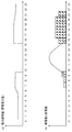
- FIG. 12A shows the amount of electric power used (the amount of electric power purchased) in the house 100. It is assumed that the house 100 stays at home from 0-23.
- the horizontal axis represents time, and the vertical axis represents power consumption (power consumption) (Wh).
- FIG. 12B shows the discharge power amount (shaded bar graph) of the power storage device 101 and the generated power amount (curve) of the power generation device 307.
- the amount of power used is kept constant at 0-10 o'clock, and the shortage is compensated by the discharge of power storage device 101 (the storage system is discharged at 7-10 o'clock).
- the power generation amount of the power generation device 307 is large, and it is not necessary to use power from the system because the generated power can sufficiently cover the required power (the power consumption is zero). Further, it is not necessary to supplement the power supply by the power storage system (the amount of discharge power is 0). That is, all the power required for load consumption is switched to the power from the power generation device 307.
- the at-home condition determination unit 203 of the present embodiment is such that the amount of generated power for each time zone is a certain value or more (however, the certain value is greater than 0), and the amount of decrease in the discharge power amount for each time zone is a certain value or more. In the case of, it is determined that the home situation in the time zone when the reduction of the discharge power amount starts is home. Therefore, it can be determined that the person is at home at 10-15.
- FIG. 1 An example in which the home status determination apparatus of the present invention is applied to a delivery system will be described.
- the delivery system of this application example includes a house 100, a house condition determination device 105 that determines the staying condition of the house 100, and a terminal 106.
- the terminal 106 is a terminal of a delivery company that delivers the house 100.
- the home status determination device 105 is connected to the user's house 100 via a network 104 such as the Internet or a LAN (Local Area Network) and a communication line 103.
- a power storage device 101 is installed in the house 100.
- the home status determination device 105 is connected to the terminal 106 via the network 104 and the communication line 103.
- the home status determination device 105 of this embodiment is centered on a CPU (Central Processing Unit) of an arbitrary computer, a memory, a program loaded in the memory, a storage unit such as a hard disk for storing the program, and a network connection interface. Realized by any combination of hardware and software. It will be understood by those skilled in the art that there are various modifications to the implementation method and apparatus.
- the program loaded in the memory includes a program downloaded from a storage medium such as a CD (Compact® Disc) or a server on the Internet in addition to a program stored in the memory from the stage of shipping the device in advance. .
- FIG. 13 is a diagram conceptually illustrating an example of a hardware configuration of the at-home situation determination apparatus 105 described in the first, second, third, and fourth embodiments.
- the home status determination device 105 includes, for example, a CPU 1300, a RAM (Random Access Memory) 1302, a ROM (Read Only Memory) 1301, a communication unit 1303, a display 1304, and an operation receiving unit that are connected to each other via a bus 8A. 1305, an operation unit 1306, and the like.
- other elements such as a microphone, a speaker, and an auxiliary storage device can also be included.
- the CPU 1300 controls the entire computer of the home status determination device 105 together with each element.
- the ROM 1301 includes an area for storing programs for operating the computer, various application programs, various setting data used when the programs operate.
- the RAM 1302 includes an area for temporarily storing data, such as a work area for operating the program.
- the operation unit 1306 includes operation keys, operation buttons, switches, a jog dial, a touch pad, a touch panel integrated with a display, and the like.
- the operation receiving unit 1305 receives user input made by the user operating the operation unit 1306.
- the communication unit 1303 can be connected to a network such as the Internet or a LAN (Local Area Network). In addition, the communication unit 1303 can connect to an external device on a one-to-one basis and communicate with the external device. The communication unit 1303 can be connected to an external device or a network by wire and / or using any wireless communication technology (short-range wireless communication, wireless LAN communication, etc.).
- a network such as the Internet or a LAN (Local Area Network).
- the communication unit 1303 can connect to an external device on a one-to-one basis and communicate with the external device.
- the communication unit 1303 can be connected to an external device or a network by wire and / or using any wireless communication technology (short-range wireless communication, wireless LAN communication, etc.).
- Display 1304 includes an LED (Light Emitting Diode) display, a liquid crystal display, an organic EL (Electro Luminescence) display, and the like.
- LED Light Emitting Diode
- liquid crystal display a liquid crystal display
- organic EL Electro Luminescence
- the house 100 includes a detached house, an apartment house, a store, a sales office, a school, a public facility, and the like.
- the house 100 is a unit that requires confirmation of the at-home situation (the presence of a person).
- An example of the house 100 is shown in FIG. Referring to FIG. 2, the power storage device 101 charges the power supplied from the power system 301 and the power generation device 307 and discharges it to the load 306.
- the load 306 is supplied with power from the system 301, the power storage device 101, and the power generation device 307.
- the power storage device 101 includes, for example, a storage battery 302, a BMU (Battery Management Unit) 303, a PCS (Power Conditioning System) 304, and a system controller 305.
- BMU Battery Management Unit
- PCS Power Conditioning System
- the storage battery 302 has a plurality of battery cells connected in series and / or in parallel, and is configured to store electric power.
- the battery cell is a secondary battery, for example, a lithium ion secondary battery, a lead storage battery, a nickel metal hydride battery, or the like.
- the BMU 303 protects and controls the storage battery 302.
- the PCS 304 is located between the BMU 303, the power system 301, the load 306, and the power generation device 307, and performs DC / AC conversion of power and adjusts voltage and frequency.
- the power system 301 is a system that is managed by a power supplier (eg, a power company) and supplies power to a power consumer.
- the power generation device 307 is a device managed by each power consumer, and the type thereof is not particularly limited.
- the power generation device 307 may be a device that generates power using natural energy such as sunlight.
- the system controller 305 centrally manages the BMU 303 and the PCS 304.
- the system controller 305 is connected to a network such as the Internet or a LAN, and transmits / receives data to / from the home status determination device 105.
- the storage battery 302, the BMU 303, the PCS 304, and the system controller 305 are separately described. This indicates that these four modules are logically separated. These modules may be physically configured separately, or at least a part thereof may be integrally formed in any combination.
- the storage battery 302 and the BMU 303 may be installed in a single casing.
- the terminal 106 is a terminal used by the delivery company.
- An example of the hardware configuration of the terminal 106 is the same as that in FIG.
- the terminal 106 may be installed at a business office of a delivery company, or may be carried by a delivery person (such as a delivery driver) who performs delivery.
- the terminal 106 transmits a home status determination request designating the scheduled delivery time (or time zone) to the house 100 to the home status determination device 105.
- the home status determination device 105 acquires charge / discharge information from the power storage device 101 and determines the home status of the house 100 at a specified time.
- the home status is determined with the user's consent.
- the user inputs whether or not he / she agrees to provide the charge / discharge information of the power storage device 101 and determine the home status using the input unit of the power storage device 101.
- the user permission information is transmitted to the home status determination device 105 through the communication line and stored in the storage unit 202.
- the user's permission may be given every time the home status is determined, or may be given at the start of use of the power storage device 101.
- the user can also select whether or not to agree for each terminal that notifies the determination result of the home status.
- the home status determination device 105 acquires the user permission information stored in the storage unit 202, and determines the home status only for the home 100 of the user who has agreed. The determination is performed by any of the methods described in the first to fourth embodiments or a combination thereof.
- the home status determination apparatus 105 notifies the terminal 106 of the determination result of the home status.
- the delivery company performs delivery to the house 100 based on the home status notified to the terminal 106.
- the terminal 106 designs a delivery route and a delivery plan based on the staying status of the plurality of houses 100.
- a delivery route is designed so that delivery can be made to the house 100 during a time period determined to be at home among the delivery destination houses 100.
- the delivery route design method can be designed using various known methods.
- the delivery route may be redesigned using the updated home status.
- the method for updating the delivery route is not particularly limited.
- the delivery route may be designed by a device different from the terminal 106.
- the designed delivery route is output through the display of the terminal 106, for example.
- SYMBOLS 100 Housing 101 Power storage device 103 Communication line 104 Network 105 Home status determination device 106 Terminal 201 Charge / discharge information acquisition means 202 Storage means 203 Home status determination means 301 Electric power system 302 Storage battery 303 BMU 304 PCS 305 System Controller 306 Load 307 Power Generation Device 801 Load Power Consumption Information Acquisition Unit 1001 Generation Power Information Acquisition Unit 1300 CPU 1301 ROM 1302 RAM 1303 Communication unit 1304 Display 1305 Operation reception unit 1306 Operation unit
Landscapes
- Engineering & Computer Science (AREA)
- Business, Economics & Management (AREA)
- Economics (AREA)
- General Physics & Mathematics (AREA)
- Physics & Mathematics (AREA)
- Strategic Management (AREA)
- Human Resources & Organizations (AREA)
- Marketing (AREA)
- Theoretical Computer Science (AREA)
- Power Engineering (AREA)
- General Business, Economics & Management (AREA)
- Tourism & Hospitality (AREA)
- Life Sciences & Earth Sciences (AREA)
- Entrepreneurship & Innovation (AREA)
- Quality & Reliability (AREA)
- Operations Research (AREA)
- Health & Medical Sciences (AREA)
- Development Economics (AREA)
- Geophysics (AREA)
- Geology (AREA)
- Remote Sensing (AREA)
- General Life Sciences & Earth Sciences (AREA)
- Environmental & Geological Engineering (AREA)
- Water Supply & Treatment (AREA)
- Public Health (AREA)
- Game Theory and Decision Science (AREA)
- General Health & Medical Sciences (AREA)
- Primary Health Care (AREA)
- General Engineering & Computer Science (AREA)
- Automation & Control Theory (AREA)
- Management, Administration, Business Operations System, And Electronic Commerce (AREA)
- Supply And Distribution Of Alternating Current (AREA)
Abstract
Priority Applications (2)
| Application Number | Priority Date | Filing Date | Title |
|---|---|---|---|
| JP2015562752A JPWO2015122196A1 (ja) | 2014-02-17 | 2015-02-13 | 在宅状況判定装置、配送システム、在宅状況判定方法、在宅状況判定プログラム、および配送端末 |
| US15/119,359 US20170052274A1 (en) | 2014-02-17 | 2015-02-13 | Resident presence-absence state determination device, delivery system, method for determining resident presence-absence state, program for determining resident presence-absence state, and terminal for delivery |
Applications Claiming Priority (2)
| Application Number | Priority Date | Filing Date | Title |
|---|---|---|---|
| JP2014-027686 | 2014-02-17 | ||
| JP2014027686 | 2014-02-17 |
Publications (1)
| Publication Number | Publication Date |
|---|---|
| WO2015122196A1 true WO2015122196A1 (fr) | 2015-08-20 |
Family
ID=53799944
Family Applications (1)
| Application Number | Title | Priority Date | Filing Date |
|---|---|---|---|
| PCT/JP2015/000672 Ceased WO2015122196A1 (fr) | 2014-02-17 | 2015-02-13 | Dispositif de détermination d'état d'occupation, système de distribution, procédé de détermination d'état d'occupation, programme de détermination d'état d'occupation et terminal de distribution |
Country Status (3)
| Country | Link |
|---|---|
| US (1) | US20170052274A1 (fr) |
| JP (1) | JPWO2015122196A1 (fr) |
| WO (1) | WO2015122196A1 (fr) |
Cited By (14)
| Publication number | Priority date | Publication date | Assignee | Title |
|---|---|---|---|---|
| JP2017062765A (ja) * | 2015-09-24 | 2017-03-30 | パナソニック インテレクチュアル プロパティ コーポレーション オブ アメリカPanasonic Intellectual Property Corporation of America | 在不在予測方法および在不在予測装置 |
| JP2017151750A (ja) * | 2016-02-25 | 2017-08-31 | シャープ株式会社 | ネットワークシステム、ネットワークシステムの処理方法、サーバ、サーバの処理方法、配達管理装置および端末 |
| JP2017211790A (ja) * | 2016-05-25 | 2017-11-30 | Necプラットフォームズ株式会社 | 情報処理装置、配達成否予測方法及び配達成否予測プログラム |
| JP2018133867A (ja) * | 2017-02-14 | 2018-08-23 | 積水化学工業株式会社 | 電力制御システムおよび電力制御方法 |
| CN108595587A (zh) * | 2018-04-19 | 2018-09-28 | 宁波三星医疗电气股份有限公司 | 基于智能电网的城市居民分布状况获取方法 |
| JP2018156495A (ja) * | 2017-03-17 | 2018-10-04 | ヤフー株式会社 | 配送処理装置、配送処理方法および配送処理プログラム |
| JP2018165965A (ja) * | 2017-03-28 | 2018-10-25 | Kddi株式会社 | 配送予定管理装置、配送予定管理方法及び配送予定管理システム |
| JP2018181291A (ja) * | 2017-04-12 | 2018-11-15 | 三井情報株式会社 | デバイス、装置、情報処理方法、情報処理システム及びプログラム |
| JP2018197890A (ja) * | 2017-05-10 | 2018-12-13 | ヤフー株式会社 | 判定装置、判定方法及び判定プログラム |
| JP2019008589A (ja) * | 2017-06-26 | 2019-01-17 | 株式会社野村総合研究所 | 集合住宅情報提供システム |
| JP2019067462A (ja) * | 2016-05-25 | 2019-04-25 | Necプラットフォームズ株式会社 | 情報処理装置、配達成否予測方法及び配達成否予測プログラム |
| WO2020230553A1 (fr) * | 2019-05-13 | 2020-11-19 | 京セラ株式会社 | Appareil d'assistance de distribution, système d'assistance de distribution et procédé d'assistance de distribution |
| JP2021073591A (ja) * | 2021-01-25 | 2021-05-13 | 株式会社野村総合研究所 | 集合住宅情報提供システム、方法、およびプログラム |
| JP7668163B2 (ja) | 2021-06-14 | 2025-04-24 | Ihi運搬機械株式会社 | 駐車場管理装置、および在宅率予測情報生成方法 |
Families Citing this family (1)
| Publication number | Priority date | Publication date | Assignee | Title |
|---|---|---|---|---|
| CN112732772A (zh) * | 2020-12-15 | 2021-04-30 | 国网湖南省电力有限公司 | 一种基于月度居民用电量的住房空置率测算方法 |
Citations (3)
| Publication number | Priority date | Publication date | Assignee | Title |
|---|---|---|---|---|
| JP2011150662A (ja) * | 2010-01-25 | 2011-08-04 | Sony Corp | 機器認証システム、及び給電制御方法 |
| JP2012181789A (ja) * | 2011-03-03 | 2012-09-20 | Hitachi Ltd | 在宅確率算出システム |
| JP2013210319A (ja) * | 2012-03-30 | 2013-10-10 | Honda Motor Co Ltd | 集配支援システム |
Family Cites Families (6)
| Publication number | Priority date | Publication date | Assignee | Title |
|---|---|---|---|---|
| US7925524B2 (en) * | 2000-07-14 | 2011-04-12 | United Parcel Service Of America, Inc. | Method and system of delivering items using overlapping delivery windows |
| US20060158037A1 (en) * | 2005-01-18 | 2006-07-20 | Danley Douglas R | Fully integrated power storage and supply appliance with power uploading capability |
| US8760115B2 (en) * | 2009-08-20 | 2014-06-24 | GM Global Technology Operations LLC | Method for charging a plug-in electric vehicle |
| JP2013020488A (ja) * | 2011-07-12 | 2013-01-31 | Toyota Motor Corp | ホームエネルギー管理システム |
| JP2013101569A (ja) * | 2011-11-09 | 2013-05-23 | Panasonic Corp | 省エネ活動管理装置、省エネ活動管理方法、プログラム |
| CN104598979B (zh) * | 2013-10-31 | 2021-10-08 | Sap欧洲公司 | 基于时间和位置的递送最优化 |
-
2015
- 2015-02-13 WO PCT/JP2015/000672 patent/WO2015122196A1/fr not_active Ceased
- 2015-02-13 US US15/119,359 patent/US20170052274A1/en not_active Abandoned
- 2015-02-13 JP JP2015562752A patent/JPWO2015122196A1/ja active Pending
Patent Citations (3)
| Publication number | Priority date | Publication date | Assignee | Title |
|---|---|---|---|---|
| JP2011150662A (ja) * | 2010-01-25 | 2011-08-04 | Sony Corp | 機器認証システム、及び給電制御方法 |
| JP2012181789A (ja) * | 2011-03-03 | 2012-09-20 | Hitachi Ltd | 在宅確率算出システム |
| JP2013210319A (ja) * | 2012-03-30 | 2013-10-10 | Honda Motor Co Ltd | 集配支援システム |
Cited By (17)
| Publication number | Priority date | Publication date | Assignee | Title |
|---|---|---|---|---|
| JP2017062765A (ja) * | 2015-09-24 | 2017-03-30 | パナソニック インテレクチュアル プロパティ コーポレーション オブ アメリカPanasonic Intellectual Property Corporation of America | 在不在予測方法および在不在予測装置 |
| JP2017151750A (ja) * | 2016-02-25 | 2017-08-31 | シャープ株式会社 | ネットワークシステム、ネットワークシステムの処理方法、サーバ、サーバの処理方法、配達管理装置および端末 |
| JP2019067462A (ja) * | 2016-05-25 | 2019-04-25 | Necプラットフォームズ株式会社 | 情報処理装置、配達成否予測方法及び配達成否予測プログラム |
| JP2017211790A (ja) * | 2016-05-25 | 2017-11-30 | Necプラットフォームズ株式会社 | 情報処理装置、配達成否予測方法及び配達成否予測プログラム |
| JP2018133867A (ja) * | 2017-02-14 | 2018-08-23 | 積水化学工業株式会社 | 電力制御システムおよび電力制御方法 |
| JP2018156495A (ja) * | 2017-03-17 | 2018-10-04 | ヤフー株式会社 | 配送処理装置、配送処理方法および配送処理プログラム |
| JP2018165965A (ja) * | 2017-03-28 | 2018-10-25 | Kddi株式会社 | 配送予定管理装置、配送予定管理方法及び配送予定管理システム |
| JP2018181291A (ja) * | 2017-04-12 | 2018-11-15 | 三井情報株式会社 | デバイス、装置、情報処理方法、情報処理システム及びプログラム |
| JP2018197890A (ja) * | 2017-05-10 | 2018-12-13 | ヤフー株式会社 | 判定装置、判定方法及び判定プログラム |
| JP2019008589A (ja) * | 2017-06-26 | 2019-01-17 | 株式会社野村総合研究所 | 集合住宅情報提供システム |
| CN108595587A (zh) * | 2018-04-19 | 2018-09-28 | 宁波三星医疗电气股份有限公司 | 基于智能电网的城市居民分布状况获取方法 |
| WO2020230553A1 (fr) * | 2019-05-13 | 2020-11-19 | 京セラ株式会社 | Appareil d'assistance de distribution, système d'assistance de distribution et procédé d'assistance de distribution |
| JP2020187454A (ja) * | 2019-05-13 | 2020-11-19 | 京セラ株式会社 | 配送支援装置、配送支援システム及び配送支援方法 |
| JP7258645B2 (ja) | 2019-05-13 | 2023-04-17 | 京セラ株式会社 | 配送支援装置、配送支援システム及び配送支援方法 |
| US12002005B2 (en) | 2019-05-13 | 2024-06-04 | Kyocera Corporation | Delivery assist apparatus, delivery assist system, and delivery assist method |
| JP2021073591A (ja) * | 2021-01-25 | 2021-05-13 | 株式会社野村総合研究所 | 集合住宅情報提供システム、方法、およびプログラム |
| JP7668163B2 (ja) | 2021-06-14 | 2025-04-24 | Ihi運搬機械株式会社 | 駐車場管理装置、および在宅率予測情報生成方法 |
Also Published As
| Publication number | Publication date |
|---|---|
| US20170052274A1 (en) | 2017-02-23 |
| JPWO2015122196A1 (ja) | 2017-03-30 |
Similar Documents
| Publication | Publication Date | Title |
|---|---|---|
| WO2015122196A1 (fr) | Dispositif de détermination d'état d'occupation, système de distribution, procédé de détermination d'état d'occupation, programme de détermination d'état d'occupation et terminal de distribution | |
| CN102738855B (zh) | 蓄电装置、蓄电方法及程序 | |
| EP2475060B1 (fr) | Système de stockage d'énergie | |
| JP6252594B2 (ja) | 蓄電池管理装置、蓄電池管理方法及びプログラム | |
| JP6216377B2 (ja) | 電力調整装置、電力調整方法、電力調整システム、蓄電装置、サーバ、プログラム | |
| JP5187776B2 (ja) | 電気機器 | |
| JP6332276B2 (ja) | 電力需給調整装置、電力システム、および電力需給調整方法 | |
| CN102959821B (zh) | 电力供应系统 | |
| JP6249895B2 (ja) | 電力制御システム、方法及び電力制御装置 | |
| JP6426922B2 (ja) | 電力システム、御装置及び充放電制御方法 | |
| EP3118962A1 (fr) | Système de partage de batterie d'accumulateurs, dispositif de traitement d'informations, procédé de partage de batterie d'accumulateurs, et programme de partage de batterie d'accumulateurs d'enregistrement de support d'enregistrement | |
| JP2013143838A (ja) | 充放電制御装置 | |
| JP2017017779A (ja) | 電力供給システムおよび電力供給方法 | |
| JP2021065097A (ja) | デマンド監視装置、デマンド監視システム、デマンド監視方法およびデマンド監視プログラム | |
| JP2020061800A (ja) | 充電方法、及び、制御装置 | |
| WO2016002346A1 (fr) | Système de commande de puissance et dispositif de commande de puissance | |
| US10284003B2 (en) | End-user based backup management | |
| JP6481942B2 (ja) | 電力管理システム、電力管理方法、およびプログラム | |
| JP2012060829A (ja) | 電力供給システム、及び電力供給方法 | |
| CN107431377B (zh) | 控制装置、控制方法以及记录介质 | |
| JP6366836B2 (ja) | 電力変換装置、電力管理装置及び電力管理方法 | |
| JP7729575B1 (ja) | 蓄電池システム | |
| JP2021027644A (ja) | 電力管理システム、電力管理方法、電力管理装置、及びプログラム | |
| JP2026034759A (ja) | 電力マネジメントシステム、及び、電力マネジメント方法 | |
| JPWO2016166854A1 (ja) | 制御装置、制御方法、及びプログラム |
Legal Events
| Date | Code | Title | Description |
|---|---|---|---|
| 121 | Ep: the epo has been informed by wipo that ep was designated in this application |
Ref document number: 15749362 Country of ref document: EP Kind code of ref document: A1 |
|
| ENP | Entry into the national phase |
Ref document number: 2015562752 Country of ref document: JP Kind code of ref document: A |
|
| WWE | Wipo information: entry into national phase |
Ref document number: 15119359 Country of ref document: US |
|
| NENP | Non-entry into the national phase |
Ref country code: DE |
|
| 122 | Ep: pct application non-entry in european phase |
Ref document number: 15749362 Country of ref document: EP Kind code of ref document: A1 |