WO2015122408A1 - 弁装置 - Google Patents
弁装置 Download PDFInfo
- Publication number
- WO2015122408A1 WO2015122408A1 PCT/JP2015/053637 JP2015053637W WO2015122408A1 WO 2015122408 A1 WO2015122408 A1 WO 2015122408A1 JP 2015053637 W JP2015053637 W JP 2015053637W WO 2015122408 A1 WO2015122408 A1 WO 2015122408A1
- Authority
- WO
- WIPO (PCT)
- Prior art keywords
- valve
- float
- main body
- seal
- valve device
- Prior art date
- Legal status (The legal status is an assumption and is not a legal conclusion. Google has not performed a legal analysis and makes no representation as to the accuracy of the status listed.)
- Ceased
Links
Images





Classifications
-
- F—MECHANICAL ENGINEERING; LIGHTING; HEATING; WEAPONS; BLASTING
- F16—ENGINEERING ELEMENTS AND UNITS; GENERAL MEASURES FOR PRODUCING AND MAINTAINING EFFECTIVE FUNCTIONING OF MACHINES OR INSTALLATIONS; THERMAL INSULATION IN GENERAL
- F16K—VALVES; TAPS; COCKS; ACTUATING-FLOATS; DEVICES FOR VENTING OR AERATING
- F16K24/00—Devices, e.g. valves, for venting or aerating enclosures
- F16K24/04—Devices, e.g. valves, for venting or aerating enclosures for venting only
- F16K24/042—Devices, e.g. valves, for venting or aerating enclosures for venting only actuated by a float
- F16K24/044—Devices, e.g. valves, for venting or aerating enclosures for venting only actuated by a float the float being rigidly connected to the valve element, the assembly of float and valve element following a substantially translational movement when actuated, e.g. also for actuating a pilot valve
-
- B—PERFORMING OPERATIONS; TRANSPORTING
- B60—VEHICLES IN GENERAL
- B60K—ARRANGEMENT OR MOUNTING OF PROPULSION UNITS OR OF TRANSMISSIONS IN VEHICLES; ARRANGEMENT OR MOUNTING OF PLURAL DIVERSE PRIME-MOVERS IN VEHICLES; AUXILIARY DRIVES FOR VEHICLES; INSTRUMENTATION OR DASHBOARDS FOR VEHICLES; ARRANGEMENTS IN CONNECTION WITH COOLING, AIR INTAKE, GAS EXHAUST OR FUEL SUPPLY OF PROPULSION UNITS IN VEHICLES
- B60K15/00—Arrangement in connection with fuel supply of combustion engines or other fuel consuming energy converters, e.g. fuel cells; Mounting or construction of fuel tanks
- B60K15/03—Fuel tanks
- B60K15/035—Fuel tanks characterised by venting means
- B60K15/03519—Valve arrangements in the vent line
-
- F—MECHANICAL ENGINEERING; LIGHTING; HEATING; WEAPONS; BLASTING
- F02—COMBUSTION ENGINES; HOT-GAS OR COMBUSTION-PRODUCT ENGINE PLANTS
- F02M—SUPPLYING COMBUSTION ENGINES IN GENERAL WITH COMBUSTIBLE MIXTURES OR CONSTITUENTS THEREOF
- F02M21/00—Apparatus for supplying engines with non-liquid fuels, e.g. gaseous fuels stored in liquid form
- F02M21/02—Apparatus for supplying engines with non-liquid fuels, e.g. gaseous fuels stored in liquid form for gaseous fuels
- F02M21/0218—Details on the gaseous fuel supply system, e.g. tanks, valves, pipes, pumps, rails, injectors or mixers
- F02M21/023—Valves; Pressure or flow regulators in the fuel supply or return system
- F02M21/0242—Shut-off valves; Check valves; Safety valves; Pressure relief valves
-
- F—MECHANICAL ENGINEERING; LIGHTING; HEATING; WEAPONS; BLASTING
- F02—COMBUSTION ENGINES; HOT-GAS OR COMBUSTION-PRODUCT ENGINE PLANTS
- F02M—SUPPLYING COMBUSTION ENGINES IN GENERAL WITH COMBUSTIBLE MIXTURES OR CONSTITUENTS THEREOF
- F02M25/00—Engine-pertinent apparatus for adding non-fuel substances or small quantities of secondary fuel to combustion-air, main fuel or fuel-air mixture
- F02M25/08—Engine-pertinent apparatus for adding non-fuel substances or small quantities of secondary fuel to combustion-air, main fuel or fuel-air mixture adding fuel vapours drawn from engine fuel reservoir
- F02M25/0836—Arrangement of valves controlling the admission of fuel vapour to an engine, e.g. valve being disposed between fuel tank or absorption canister and intake manifold
-
- B—PERFORMING OPERATIONS; TRANSPORTING
- B60—VEHICLES IN GENERAL
- B60K—ARRANGEMENT OR MOUNTING OF PROPULSION UNITS OR OF TRANSMISSIONS IN VEHICLES; ARRANGEMENT OR MOUNTING OF PLURAL DIVERSE PRIME-MOVERS IN VEHICLES; AUXILIARY DRIVES FOR VEHICLES; INSTRUMENTATION OR DASHBOARDS FOR VEHICLES; ARRANGEMENTS IN CONNECTION WITH COOLING, AIR INTAKE, GAS EXHAUST OR FUEL SUPPLY OF PROPULSION UNITS IN VEHICLES
- B60K15/00—Arrangement in connection with fuel supply of combustion engines or other fuel consuming energy converters, e.g. fuel cells; Mounting or construction of fuel tanks
- B60K15/03—Fuel tanks
- B60K2015/03256—Fuel tanks characterised by special valves, the mounting thereof
- B60K2015/03289—Float valves; Floats therefor
-
- B—PERFORMING OPERATIONS; TRANSPORTING
- B60—VEHICLES IN GENERAL
- B60K—ARRANGEMENT OR MOUNTING OF PROPULSION UNITS OR OF TRANSMISSIONS IN VEHICLES; ARRANGEMENT OR MOUNTING OF PLURAL DIVERSE PRIME-MOVERS IN VEHICLES; AUXILIARY DRIVES FOR VEHICLES; INSTRUMENTATION OR DASHBOARDS FOR VEHICLES; ARRANGEMENTS IN CONNECTION WITH COOLING, AIR INTAKE, GAS EXHAUST OR FUEL SUPPLY OF PROPULSION UNITS IN VEHICLES
- B60K15/00—Arrangement in connection with fuel supply of combustion engines or other fuel consuming energy converters, e.g. fuel cells; Mounting or construction of fuel tanks
- B60K15/03—Fuel tanks
- B60K15/035—Fuel tanks characterised by venting means
- B60K2015/03542—Mounting of the venting means
- B60K2015/03557—Mounting of the venting means comprising elements of the venting device integrated in the fuel tank, e.g. vapor recovery means
-
- B—PERFORMING OPERATIONS; TRANSPORTING
- B60—VEHICLES IN GENERAL
- B60K—ARRANGEMENT OR MOUNTING OF PROPULSION UNITS OR OF TRANSMISSIONS IN VEHICLES; ARRANGEMENT OR MOUNTING OF PLURAL DIVERSE PRIME-MOVERS IN VEHICLES; AUXILIARY DRIVES FOR VEHICLES; INSTRUMENTATION OR DASHBOARDS FOR VEHICLES; ARRANGEMENTS IN CONNECTION WITH COOLING, AIR INTAKE, GAS EXHAUST OR FUEL SUPPLY OF PROPULSION UNITS IN VEHICLES
- B60K15/00—Arrangement in connection with fuel supply of combustion engines or other fuel consuming energy converters, e.g. fuel cells; Mounting or construction of fuel tanks
- B60K15/03—Fuel tanks
- B60K15/035—Fuel tanks characterised by venting means
- B60K2015/03561—Venting means working at specific times
- B60K2015/03576—Venting during filling the reservoir
-
- Y—GENERAL TAGGING OF NEW TECHNOLOGICAL DEVELOPMENTS; GENERAL TAGGING OF CROSS-SECTIONAL TECHNOLOGIES SPANNING OVER SEVERAL SECTIONS OF THE IPC; TECHNICAL SUBJECTS COVERED BY FORMER USPC CROSS-REFERENCE ART COLLECTIONS [XRACs] AND DIGESTS
- Y02—TECHNOLOGIES OR APPLICATIONS FOR MITIGATION OR ADAPTATION AGAINST CLIMATE CHANGE
- Y02T—CLIMATE CHANGE MITIGATION TECHNOLOGIES RELATED TO TRANSPORTATION
- Y02T10/00—Road transport of goods or passengers
- Y02T10/10—Internal combustion engine [ICE] based vehicles
- Y02T10/30—Use of alternative fuels, e.g. biofuels
Definitions
- the present invention relates to an improvement of a valve device that is attached to a fuel tank of an automobile or a two-wheeled vehicle and functions so as to communicate between the inside and outside of the fuel tank in an open state.
- Patent Document 1 discloses a valve device that constitutes a ventilation passage of a fuel tank, which includes a float that rises due to the inflow of fuel into a case and closes a valve port connected to the passage to the outside of the tank. There is something.
- the thing of the said patent document 1 closes the said valve port with the plate-shaped valve body provided in the upper part of the float main body so that tilting was possible. Thereby, in the thing of patent document 1, it can begin to solve the contact state of this valve body and valve opening from the inclination lower side of the tilted valve body, and even if the pressure difference inside and outside the fuel tank is large, The transition to the valve open state is made smoothly.
- the main problem to be solved by the present invention is that a valve device using this type of float can smoothly transition from the closed state to the open state, and at the same time as the valve is opened, It is in the point which can respond well to the request
- the valve device has a float and a case for housing the valve device, and constitutes a part of the vent passage of the fuel tank.
- the float includes a float main body and a valve body that is tiltably provided on an upper portion of the float main body.
- the valve body includes a seal portion that closes a valve port formed in the case when the float is lifted, a link portion with respect to the float main body, and a contact portion that is in contact with the vicinity of the valve port during the tilting.
- Have The contact portion is configured to protrude laterally from the seal portion with a horizontal area smaller than that of the seal portion.
- a valve apparatus that has a float and a case for storing the float, and constitutes a part of a ventilation passage of the fuel tank,
- the float includes a float main body and a valve body that is tiltably provided on an upper portion of the float main body.
- the valve body is provided on a side opposite to the seal portion sandwiching the seal portion, a seal portion that closes a valve port formed in the case when the float is lifted, a link portion with respect to the float main body, and the seal portion.
- An abutting portion that abuts in the vicinity of the valve opening during the tilting, and has a length with the linking portion as one end and the abutting portion as the other end,
- the width of the seal portion is larger than the width of the valve port, and the width of the contact portion is smaller than the width of the seal portion.
- the valve port When the fuel flows into the case, the valve port is closed by the seal portion of the float valve body that is raised thereby, preventing the fuel from flowing into the upper chamber.
- the float When the fuel flows out of the case, the float can be lowered.
- the valve body abuts the abutting portion in the vicinity of the valve opening.
- the seal portion is tilted so that the linkage portion side is inclined downward with the contact portion as a fulcrum, and the seal portion is released from the valve port. Thereby, even when the inside of the tank is at a high pressure, smooth valve opening is realized.
- the contact portion is moved to the center side of the valve port as the float descends.
- the horizontal area of the contact portion is a seal.
- the valve body has a length with the linkage portion as one end and the contact portion as the other end. And the width of the seal portion is larger than the width of the valve port, and the width of the contact portion is smaller than the width of the seal portion. The abutting portion does not hinder the flow of gas in the tank through the tank to the outside as much as possible.
- a ventilation portion is formed in the contact portion. Moreover, it is set as one of the preferable aspects of this invention to make the said ventilation
- valve body If a recess is formed in the lower portion of the seal portion to receive the protrusion formed on the upper portion of the float main body, the valve body is placed horizontally on the float main body except during the valve opening. It can be supported stably in the state.
- valve body is provided with a restricting portion that is caught by a part of the float main body at a predetermined tilt position of the valve body and prevents further tilting, the tilt of the valve body is constant.
- the valve body can be prevented from unexpectedly falling off from the float main body.
- the gas in the tank is allowed to flow out of the tank at a large flow rate at the same time as the valve opening while making the transition from the valve closing state to the valve opening state smooth in the valve device using the float. Is possible.
- FIG. 1 is a side view of a valve device according to an embodiment of the present invention.
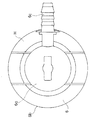
- FIG. 2 is a plan view of the valve device.
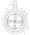
- FIG. 3 is a bottom view of the valve device.
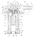
- FIG. 4 is a cross-sectional view of the valve device, showing a closed state.
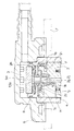
- FIG. 5 is a cross-sectional view of the main part of the valve device, showing a closed state.
- FIG. 6 is a cross-sectional view of the main part of the valve device, showing a state immediately after the float is lowered and opened from the state of FIG.
- FIG. 7 is a perspective view of a float main body constituting the valve device.
- FIG. 8 is a plan view of the float main body.
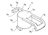
- FIG. 9 is a perspective view of a valve body constituting the valve device.
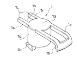
- FIG. 10 is a perspective view of a valve body constituting the valve device, and shows the valve body from the lower side of FIG.
- FIG. 11 is a perspective view showing a partial modification of the configuration of the valve body.
- FIG. 12 is a perspective view showing a partial modification of the configuration of the valve body.
- FIG. 13 is a perspective view showing a partial modification of the configuration of the valve body.
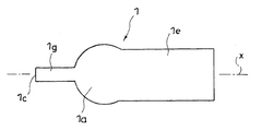
- FIG. 14 is a plan view showing a partial modification of the configuration of the valve body.
- FIG. 15 is a plan view showing a partial modification of the configuration of the valve body.
- the valve device according to this embodiment is attached to a fuel tank T of an automobile or a two-wheeled automobile, and functions so as to communicate between the inside and outside of the fuel tank T in the opened state.
- a valve device is typically attached to the upper part of the fuel tank T and constitutes a part of the ventilation channel C of the fuel tank T.
- Such a valve device uses a mounting hole Tb provided in the fuel tank T as in the illustrated example, or uses a bracket or the like provided in the fuel tank T although not shown in the figure.
- the tank T can be provided.
- Such a valve device has a float F and a case H for housing it (see FIG. 4).
- the case H has a partition wall 5 that divides the inside of the case H into an upper chamber 3 and a storage chamber 4 for the float F.
- the upper chamber 3 is on the partition wall 5 and communicates with the tank outside Ta via the exhaust port 6c.
- the storage chamber 4 is below the partition wall 5, and the float F is stored therein so as to be movable up and down. Fuel can flow into the storage chamber 4 from an inflow portion 8a formed in a cap 8 described later that constitutes the bottom portion of the case H.
- the float F When the float F is in a lowered position with its lower end in contact with the bottom of the case H (not shown), the inside and outside of the tank are the inflow portion 8a, the valve port 5a formed in the partition wall 5, the exhaust port You will be contacted through 6c.
- the opening edge of the valve port 5a facing the storage chamber 4 serves as a valve seat 5b, and the float F seats the valve body 1 provided on the valve seat 5b on the valve seat 5b. It is raised to the position to make it. As a result, the communication inside and outside the tank is blocked.
- the float F descends again and the inside and outside of the tank are communicated again via the valve device.
- the case H is formed by combining a flange 6, a case main body 7, and a cap 8. These are typically made of plastic.
- the case main body 7 has a substantially cylindrical shape having the valve port 5a in the center on the upper side and having the lower end opened.
- the upper portion of the case main body 7 has a smaller diameter than the remaining portions, and the stepped surface 7c is formed outside the upper portion of the case main body 7 by the reduced diameter portion 7a. Further, a circumferential groove 7b is formed on the outer peripheral portion of the reduced diameter portion 7a.
- the reduced diameter portion 7 a is separated from the remaining portions by the partition wall 5.
- the valve port 5a is configured by fitting a short cylindrical valve seat structure 5d having an outer flange 5e at the upper end into a through hole 5c formed at the center of the partition wall 5 from above. (See FIG. 6).
- the lower end of the valve seat structure 5d that abuts the outer flange 5e against the through hole 5c and projects the lower end downward from the through hole 5c functions as the valve seat 5b.
- the flange 6 has an inner diameter substantially equal to the outer diameter of the reduced diameter portion 7a of the case main body 7, and closes the upper end of the tube and opens the lower end of the tube, and the short tubular portion 6a.
- 6a is provided with an outer flange portion 6b formed at the lower end of the cylinder 6a, and an exhaust port 6c having a tubular shape extending in the lateral direction with one end of the pipe communicating with the side portion of the short cylindrical portion 6a (see FIG. 4). ).
- the case main body 7 and the flange 6 are formed by fitting the reduced diameter portion 7a of the case main body 7 into the short cylindrical portion 6a until the circumferential step surface 7c of the case main body 7 abuts against the outer flange portion 6b of the flange 6. It comes to be integrated with. In the state where the case main body 7 and the flange 6 are combined in this way, a space serving as the upper chamber 3 is formed between the reduced diameter portion 7a and the closed end of the short tubular portion 6a.
- reference symbol R denotes a seal ring that is attached to the reduced diameter portion 7a using the circumferential groove 7b. The seal ring R seals between the reduced diameter portion 7a and the short cylindrical portion 6a in an airtight state.
- reference numeral 7 d denotes an engaging portion formed on the outer side of the case main body 7.
- the case main body 7 is configured by engaging the engaging portion 7 d with the engaged portion 6 d of the flange 6. And the flange 6 are maintained in the assembled state.
- the cap 8 includes a short cylindrical portion 8b having an inner diameter substantially equal to the outer diameter of the lower end of the case main body 7, and a bottom plate 8c for closing the cylindrical lower end of the short cylindrical portion 8b (see FIG. 4). ).
- the engagement protrusion 7 e formed on the case main body 7 becomes the short cylindrical portion of the cap 8.
- the lower end of the case main body 7 is closed by the cap 8 by being engaged with the engagement window 8d formed on the 8b, and the float F in the lowered position is supported by the bottom plate 8c of the cap 8. ing.
- the inflow portion 8 a is formed on the bottom plate 8 c of the cap 8.
- the valve device is typically used as an outer surface portion of the fuel tank T with the outer flange portion 6b of the flange 6 inserted in a mounting hole Tb formed in the upper portion of the fuel tank T below the flange 6. Is fixed to the fuel tank T by welding.
- the exhaust port 6c is adapted to be fitted into one end of the pipe body P constituting the ventilation channel C.
- a disk-like weight 9 is accommodated on the partition wall 5 in the reduced diameter portion 7a (see FIG. 4), and the valve port 5a is normally used by the weight 9 as described above. It is closed from the upper chamber 3 side.
- reference numeral 10 denotes a seat interposed between the valve seat structure 5 d and the weight 9, and a communication opening to the valve port 5 a is formed at the center of the seat 10.
- the float F includes a float main body 2 and a valve body 1 provided on the top of the float main body 2 so as to be tiltable (see FIG. 5).
- the float main body 2 has a cylindrical shape in which the upper end is substantially closed and an annular space 2b is formed around the core portion 2a, and the annular space 2b is opened on the lower end side ( (See FIG. 4).
- the upper end of the spring is brought into contact with the inner back portion of the annular space 2b, and the lower end of the spring is brought into contact with the bottom plate 8c of the cap 8, so The compression coil spring 11 that always operates is accommodated.
- the valve body 1 includes a seal portion 1a that closes the valve port 5a when the float F is raised, an engagement portion 1b that is a linkage portion that links the float body 2 with respect to the float main body 2 in a tiltable manner, And a contact portion 1c that contacts the vicinity of the valve port 5a during the tilting (see FIG. 9).
- the contact portion 1c has a horizontal area smaller than that of the seal portion 1a and protrudes laterally from the seal portion 1a.
- the valve body 1 includes a main body portion 1d having a short cylindrical shape whose upper end is closed and whose lower end is opened, and on the upper end side of the main body portion 1d from the side portion of the main body portion 1d to the side.
- a protruding first arm portion 1e and a second arm portion 1g are provided.
- the main part 1d has a slightly larger outer diameter than the valve port 5a, and the upper end of the main part 1d functions as the seal part 1a.
- the second arm portion 1g protrudes laterally from the side portion of the main portion 1d on the side opposite to the first arm portion 1e.
- the second arm portion 1g functions as the contact portion 1c.
- the second arm portion 1g has an outer shape that follows an imaginary quadrangular outer shape that has a smaller area in the horizontal direction than the seal portion 1a in a plan view, and a vent portion 1h on the inside thereof. It has a frame shape with through holes 1i. That is, in this embodiment, as shown in FIG.
- the valve body 1 includes a seal portion 1 a that closes the valve port 5 a formed in the case H when the float F is raised, It is provided on the opposite side of the engaging portion 1b that becomes the linking portion with respect to the float main body 2 and the engaging portion 1b that becomes the linking portion across the seal portion 1a, and comes into contact with the vicinity of the valve port 5a during the tilting.
- the contact portion 1c has a length with the engagement portion 1b serving as the linkage portion as one end and the contact portion 1c as the other end.
- the width of the seal portion 1a is larger than the width of the valve port 5a, and the width of the contact portion 1c is smaller than the width of the seal portion 1a.
- the projecting dimension of the first arm 1e from the main body 1d is larger than that of the second arm 1g.
- the first arm 1e is slightly curved with its protruding end facing downward, and has a protruding portion 1f protruding toward the main body 1d at the protruding end (see FIG. 10).
- the engaging portion 1b having a hook shape is provided on the protruding end side.
- the space between the base portion of the first arm portion 1e and the protruding end is open, and the first arm portion 1e has a frame shape.
- an upper recess 2c for accommodating the valve body 1 is formed.
- the upper recess 2c includes a circular hole-shaped central portion 2d for accommodating the main portion 1d of the valve body 1, a first groove portion 2e for accommodating the first arm portion 1e, and a second groove portion 2f for accommodating the second arm portion 1g. (See FIG. 7).
- the first groove 2 e is opened at the side of the float main body 2.
- the groove end opposite to the groove end on the communication side with the central portion 2d in the second groove portion 2f is not opened at the side portion of the float main body 2.
- a column part 2g protruding upward from the bottom of the central part 2d is formed in the central part 2d.
- an island-shaped protrusion 2h is formed on the open side.
- an engagement hole 2i that opens at the side of the float main body 2 and goes toward the center of the float main body 2 (see FIG. 5).
- the valve body 1 is supported so as to be tiltable on the column portion 2g by accommodating the column portion 2g inside the main body portion 1d.
- the recessed part 1j which accommodates the protrusion 2j formed in the upper part of the said float main body 2 is formed in the lower part of the said seal part 1a (refer FIG. 10). Except when the valve is opened, the valve body 1 is stably supported on the float main body 2 in a state where the seal portion 1a is horizontal.
- valve body 1 is engaged with the float main body 2 in the tiltable state by inserting the engagement portion 1b of the first arm 1e into the engagement hole 2i of the float main body 2 (FIG. 6). reference).
- the island-like protrusion 2h is settled inside the 1st arm part 1e.
- valve port 5a When the fuel flows into the case, the valve port 5a is closed by the wide seal portion 1a of the valve body 1 of the float F that is raised by this, and the flow of fuel into the upper chamber 3 is prevented.
- the float F can be lowered.
- the float F and the valve body 1 are linked on the engagement portion 1b side and not on the contact portion 1c side. 1 abuts the abutting portion 1c in the vicinity of the valve port 5a, and tilts the engaging portion 1b with the abutting portion as a fulcrum so that the seal portion 1a is separated from the valve port 5a. (See FIG. 6). Thereby, even when the inside of the tank is at a high pressure, smooth valve opening is realized.
- the abutting portion 1c is moved to the center side of the valve port 5a as the float F descends.
- the horizontal area of the abutting portion 1c is larger than the horizontal area of the seal portion 1a. Since the width of the seal portion 1a is larger than the width of the valve port 5a and the width of the contact portion 1c is smaller than the width of the seal 1a portion, the valve is opened. It is possible to prevent the contact portion 1c from interfering with the flow of gas in the tank to the outside of the tank through the valve port 5a that occurs at the same time as much as possible. That is, the valve device according to this embodiment can well meet the request for flowing the gas in the tank out of the tank at a large flow rate simultaneously with the opening of the valve.
- the contact portion 1c is provided with a through hole 1i serving as the ventilation portion 1h (see FIG. 9). The simultaneous gas flow is further prevented.
- valve body 1 is provided with a restricting portion 1k that is caught by a part of the float main body 2 at a predetermined tilting position of the valve body 1 and prevents further tilting. I am letting.
- a leg portion 1m having a claw portion 1n protruding outward from the leg end is integrally formed at the lower end of the main body portion 1d of the valve body 1 and directly below the contact portion 1c. (See FIG. 10).
- a side recess 2k that opens at the side of the float main body 2 and continues to the center side of the float main body 2 (see FIG. 7).
- the part recess 2k and the upper recess 2c are communicated between the column part 2g and the second groove part 2f through a notch part 2m that cuts a part of the bottom wall and the side wall of the center part 2d. (See FIG. 4).
- the said valve body 1 is supported by the upper part of the float main body 2 as mentioned above in the state which made the said leg part 1m enter the side part recess 2k through this notch part 2m.
- the claw portion 1n of the leg portion 1m is caught by the upper end 2n of the notch portion 2m.
- the tilting of the valve body 1 is performed within a certain range, and the valve body 1 is prevented from unexpectedly falling off from the float main body 2.
- the abutment portion 1c may have a horizontal area smaller than that of the seal portion 1a, and more preferably has a configuration including the ventilation portion 1h. The specific configuration may be changed as necessary. Absent.
- FIG. 11 shows the contact from the first rod-shaped portion 1p projecting sideways from the main body portion 1d and the second rod-shaped portion 1q extending from the projecting end of the first rod-shaped portion 1p in a direction crossing the first rod-shaped portion 1p. The example which comprised the contact part 1c is shown. In the example of FIG. 11, the ventilation portion 1h is between the second rod-like portion 1q and the main portion 1d. Further, FIG.
- the valve body 1 has a length with the engaging portion 1 b serving as the linkage portion as one end and the abutting portion 1 c as the other end, and the width of the seal portion 1 a.
- the ventilation portion 1h is not provided in the contact portion 1c. Moreover, it is not open
- the contact portion 1 c is a rod-like shape that protrudes from the seal portion 1 a along an imaginary center line x passing through the center of the seal portion 1 a and along the length direction of the valve body 1.
- the contact portion 1 c protrudes from the seal portion 1 a along an imaginary center line x passing through the center of the seal portion 1 a and along the length direction of the valve body 1.
- released between the base of the 1st arm part 1e, and the protrusion end, and the 1st arm part 1e is exhibiting plate shape.
- the present invention is not limited to the embodiment described above, but includes all embodiments that can achieve the object of the present invention. It should be noted that the entire content of the specification, claims, drawings and abstract of Japanese Patent Application No. 2014-024393 filed on February 12, 2014 is cited herein as the disclosure of the specification of the present invention. Incorporate.
Landscapes
- Engineering & Computer Science (AREA)
- General Engineering & Computer Science (AREA)
- Mechanical Engineering (AREA)
- Chemical & Material Sciences (AREA)
- Combustion & Propulsion (AREA)
- Sustainable Development (AREA)
- Life Sciences & Earth Sciences (AREA)
- Sustainable Energy (AREA)
- Transportation (AREA)
- Oil, Petroleum & Natural Gas (AREA)
- General Chemical & Material Sciences (AREA)
- Chemical Kinetics & Catalysis (AREA)
- Self-Closing Valves And Venting Or Aerating Valves (AREA)
- Float Valves (AREA)
- Cooling, Air Intake And Gas Exhaust, And Fuel Tank Arrangements In Propulsion Units (AREA)
Abstract
Description
前記フロートは、フロート主体と、このフロート主体の上部に傾動可能に備えられた弁体とを備えてなり、
前記弁体は、前記フロートの上昇時に前記ケース内に形成された弁口を閉塞するシール部と、前記フロート主体に対する連係部と、前記傾動時に前記弁口の近傍に当接する当接部とを有しており、
前記当接部を、水平方向の面積を前記シール部よりも小さくして前記シール部から側方に突き出した構成としたものとした。
また、前記課題を達成するために、この発明にあっては、第二の観点から、弁装置を、
フロートと、これを収納するケースとを有し、燃料タンクの通気流路の一部を構成する弁装置であって、
前記フロートは、フロート主体と、このフロート主体の上部に傾動可能に備えられた弁体とを備えてなり、
前記弁体は、前記フロートの上昇時に前記ケース内に形成された弁口を閉塞するシール部と、前記フロート主体に対する連係部と、前記シール部を挟んだ前記連係部と反対の側に備えられて前記傾動時に前記弁口の近傍に当接する当接部とを有し、前記連係部を一端とし且つ前記当接部を他端とした長さを備えており、
前記シール部の幅は前記弁口の幅よりも大きく、前記当接部の幅は前記シール部の幅よりも小さくさせてなる、ものとした。
すなわち、この実施の形態にあっては、図9に示すように、前記弁体1は、前記フロートFの上昇時に前記ケースH内に形成された弁口5aを閉塞するシール部1aと、前記フロート主体2に対する連係部となる係合部1bと、前記シール部1aを挟んだ前記連係部となる係合部1bと反対の側に備えられて前記傾動時に前記弁口5aの近傍に当接する当接部1cとを有し、前記連係部となる係合部1bを一端とし且つ前記当接部1cを他端とした長さを備えている。また、前記シール部1aの幅は前記弁口5aの幅よりも大きく、前記当接部1cの幅は前記シール部1aの幅よりも小さくなっている。
図13に示される例では、前記弁体1は、前記連係部となる係合部1bを一端とし且つ前記当接部1cを他端とした長さを備え、また、前記シール部1aの幅は前記弁口5aの幅よりも大きく、前記当接部1cの幅は前記シール部1aの幅よりも小さくなっているが、前記当接部1cには前記通気部1hは設けられていない。また、第一腕部1eの基部と突き出し端との間は開放されておらず、第一腕部1eは板状を呈している。
図14に示される例では、前記当接部1cは、前記シール部1aの中心を通り且つ前記弁体1の長さ方向に沿った仮想の中心線xに沿って前記シール部1aから突き出す棒状を呈している。また、第一腕部1eの基部と突き出し端との間は開放されておらず、第一腕部1eは板状を呈している。
図15に示される例では、前記当接部1cは、前記シール部1aの中心を通り且つ前記弁体1の長さ方向に沿った仮想の中心線xに沿って前記シール部1aから突き出す長さ側棒状体1gaと、この長さ側棒状体の突き出し端に幅方向中程の位置を一体に連接させた幅側棒状体1gbとから構成されている。また、第一腕部1eの基部と突き出し端との間は開放されておらず、第一腕部1eは板状を呈している。
なお、2014年2月12日に出願された日本特許出願第2014-024393号の明細書、特許請求の範囲、図面及び要約書の全内容をここに引用し、本発明の明細書の開示として、取り入れるものである。
Claims (7)
- フロートと、これを収納するケースとを有し、燃料タンクの通気流路の一部を構成する弁装置であって、
前記フロートは、フロート主体と、このフロート主体の上部に傾動可能に備えられた弁体とを備えてなり、
前記弁体は、前記フロートの上昇時に前記ケース内に形成された弁口を閉塞するシール部と、前記フロート主体に対する連係部と、前記傾動時に前記弁口の近傍に当接する当接部とを有しており、
前記当接部は、水平方向の面積を前記シール部よりも小さくして前記シール部から側方に突き出した構成となっている、弁装置。 - 前記当接部に通気部を形成させてなる、請求項1に記載の弁装置。
- 前記通気部を、貫通穴としてなる、請求項2に記載の弁装置。
- 前記当接部は、前記シール部を挟んだ前記連係部と反対の側に備えられてなる、請求項1~請求項3のいずれか1項に記載の弁装置。
- 前記シール部の下部に、前記フロート主体の上部に形成された突部を納める凹部を形成させてなる、請求項1~請求項4のいずれか1項に記載の弁装置。
- 前記弁体に、この弁体の所定の傾動位置において前記フロート主体の一部に引っかかってそれ以上の前記傾動を阻止する規制部を備えさせてなる、請求項1~請求項5のいずれか1項に記載の弁装置。
- フロートと、これを収納するケースとを有し、燃料タンクの通気流路の一部を構成する弁装置であって、
前記フロートは、フロート主体と、このフロート主体の上部に傾動可能に備えられた弁体とを備えてなり、
前記弁体は、前記フロートの上昇時に前記ケース内に形成された弁口を閉塞するシール部と、前記フロート主体に対する連係部と、前記シール部を挟んだ前記連係部と反対の側に備えられて前記傾動時に前記弁口の近傍に当接する当接部とを有し、前記連係部を一端とし且つ前記当接部を他端とした長さを備えており、
前記シール部の幅は前記弁口の幅よりも大きく、前記当接部の幅は前記シール部の幅よりも小さくさせてなる、弁装置。
Priority Applications (4)
| Application Number | Priority Date | Filing Date | Title |
|---|---|---|---|
| US15/118,237 US10161538B2 (en) | 2014-02-12 | 2015-02-10 | Valve device |
| JP2015562826A JP6203296B2 (ja) | 2014-02-12 | 2015-02-10 | 弁装置 |
| CN201580007868.7A CN105980751B (zh) | 2014-02-12 | 2015-02-10 | 阀装置 |
| EP15749543.3A EP3106725B1 (en) | 2014-02-12 | 2015-02-10 | Valve device |
Applications Claiming Priority (2)
| Application Number | Priority Date | Filing Date | Title |
|---|---|---|---|
| JP2014024393 | 2014-02-12 | ||
| JP2014-024393 | 2014-02-12 |
Publications (1)
| Publication Number | Publication Date |
|---|---|
| WO2015122408A1 true WO2015122408A1 (ja) | 2015-08-20 |
Family
ID=53800151
Family Applications (1)
| Application Number | Title | Priority Date | Filing Date |
|---|---|---|---|
| PCT/JP2015/053637 Ceased WO2015122408A1 (ja) | 2014-02-12 | 2015-02-10 | 弁装置 |
Country Status (5)
| Country | Link |
|---|---|
| US (1) | US10161538B2 (ja) |
| EP (1) | EP3106725B1 (ja) |
| JP (1) | JP6203296B2 (ja) |
| CN (1) | CN105980751B (ja) |
| WO (1) | WO2015122408A1 (ja) |
Cited By (3)
| Publication number | Priority date | Publication date | Assignee | Title |
|---|---|---|---|---|
| WO2018077541A1 (de) * | 2016-10-24 | 2018-05-03 | Robert Bosch Gmbh | Blasenfreie niederdruckpumpe für verflüssigtes gas |
| WO2020105541A1 (ja) * | 2018-11-20 | 2020-05-28 | 株式会社パイオラックス | 弁装置 |
| WO2022158489A1 (ja) * | 2021-01-25 | 2022-07-28 | 株式会社パイオラックス | 弁装置 |
Families Citing this family (6)
| Publication number | Priority date | Publication date | Assignee | Title |
|---|---|---|---|---|
| WO2020164806A1 (en) * | 2019-02-13 | 2020-08-20 | Eaton Intelligent Power Limited | Multi-material orifice plates for vent valve assemblies of liquid containment systems |
| JP7138610B2 (ja) * | 2019-10-10 | 2022-09-16 | 株式会社ニフコ | 燃料タンク用弁装置 |
| WO2021132035A1 (ja) * | 2019-12-24 | 2021-07-01 | 株式会社パイオラックス | 弁装置 |
| JP7707052B2 (ja) * | 2021-12-21 | 2025-07-14 | 株式会社パイオラックス | 弁装置 |
| CN116624640B (zh) * | 2023-06-27 | 2026-04-21 | 上海大创汽车技术有限公司 | 安全阀与气液分离器 |
| CN117072732B (zh) * | 2023-10-18 | 2024-01-02 | 斯丹德汽车系统(苏州)有限公司 | 一种坡度排气阀及其工作方法 |
Citations (3)
| Publication number | Priority date | Publication date | Assignee | Title |
|---|---|---|---|---|
| US5313977A (en) * | 1992-11-12 | 1994-05-24 | G. T. Products, Inc. | Fluid-responsive vent control valve with peel-away opening action |
| US5988201A (en) * | 1998-07-31 | 1999-11-23 | Sparco, Inc. | Automatic vent having a multi-hinged valve |
| US7543597B2 (en) * | 2005-10-07 | 2009-06-09 | Alfmeier Corporation | Vent valve assembly with lever arrangement |
Family Cites Families (9)
| Publication number | Priority date | Publication date | Assignee | Title |
|---|---|---|---|---|
| US4886089A (en) | 1988-05-27 | 1989-12-12 | Gt Development Corporation | Gas venting valve for liquid tank |
| JP3152100B2 (ja) * | 1995-03-28 | 2001-04-03 | 豊田合成株式会社 | 逆止弁及びこれを用いた燃料タンク |
| US5960817A (en) * | 1997-11-03 | 1999-10-05 | Walbro Corporation | Control valve and system for fuel vapor recovery |
| US5950659A (en) * | 1998-07-15 | 1999-09-14 | Saturn Electronics & Engineering, Inc. | Vehicle fuel vapor vent valve |
| US6371152B1 (en) * | 2000-02-09 | 2002-04-16 | Eaton Corporation | Method of controlling vapor venting in a fuel tank and valve therefor |
| US7819129B2 (en) * | 2003-02-18 | 2010-10-26 | Keefer Neal L | Relief vent including float and seal |
| KR100879059B1 (ko) * | 2006-11-14 | 2009-01-15 | 기아자동차주식회사 | 컷 밸브 |
| JP4972454B2 (ja) * | 2007-04-26 | 2012-07-11 | 株式会社ニフコ | 燃料タンク用弁装置 |
| WO2014011229A1 (en) | 2012-07-12 | 2014-01-16 | Eaton Corporation | Flapper valve with guide legs |
-
2015
- 2015-02-10 WO PCT/JP2015/053637 patent/WO2015122408A1/ja not_active Ceased
- 2015-02-10 JP JP2015562826A patent/JP6203296B2/ja active Active
- 2015-02-10 EP EP15749543.3A patent/EP3106725B1/en active Active
- 2015-02-10 CN CN201580007868.7A patent/CN105980751B/zh active Active
- 2015-02-10 US US15/118,237 patent/US10161538B2/en active Active
Patent Citations (3)
| Publication number | Priority date | Publication date | Assignee | Title |
|---|---|---|---|---|
| US5313977A (en) * | 1992-11-12 | 1994-05-24 | G. T. Products, Inc. | Fluid-responsive vent control valve with peel-away opening action |
| US5988201A (en) * | 1998-07-31 | 1999-11-23 | Sparco, Inc. | Automatic vent having a multi-hinged valve |
| US7543597B2 (en) * | 2005-10-07 | 2009-06-09 | Alfmeier Corporation | Vent valve assembly with lever arrangement |
Cited By (7)
| Publication number | Priority date | Publication date | Assignee | Title |
|---|---|---|---|---|
| WO2018077541A1 (de) * | 2016-10-24 | 2018-05-03 | Robert Bosch Gmbh | Blasenfreie niederdruckpumpe für verflüssigtes gas |
| WO2020105541A1 (ja) * | 2018-11-20 | 2020-05-28 | 株式会社パイオラックス | 弁装置 |
| JPWO2020105541A1 (ja) * | 2018-11-20 | 2021-12-09 | 株式会社パイオラックス | 弁装置 |
| JP7049483B2 (ja) | 2018-11-20 | 2022-04-06 | 株式会社パイオラックス | 弁装置 |
| WO2022158489A1 (ja) * | 2021-01-25 | 2022-07-28 | 株式会社パイオラックス | 弁装置 |
| JPWO2022158489A1 (ja) * | 2021-01-25 | 2022-07-28 | ||
| JP7488918B2 (ja) | 2021-01-25 | 2024-05-22 | 株式会社パイオラックス | 弁装置 |
Also Published As
| Publication number | Publication date |
|---|---|
| JP6203296B2 (ja) | 2017-09-27 |
| EP3106725B1 (en) | 2021-10-13 |
| EP3106725A4 (en) | 2017-12-20 |
| CN105980751A (zh) | 2016-09-28 |
| US10161538B2 (en) | 2018-12-25 |
| US20170175912A1 (en) | 2017-06-22 |
| JPWO2015122408A1 (ja) | 2017-03-30 |
| EP3106725A1 (en) | 2016-12-21 |
| CN105980751B (zh) | 2019-07-05 |
Similar Documents
| Publication | Publication Date | Title |
|---|---|---|
| JP6203296B2 (ja) | 弁装置 | |
| JP5242440B2 (ja) | 燃料タンク用弁装置及び燃料タンク用過給油防止装置 | |
| JP5091689B2 (ja) | フロート弁装置 | |
| JP6203205B2 (ja) | 弁装置 | |
| US10279679B2 (en) | Valve device | |
| JP6157404B2 (ja) | 弁装置 | |
| JP6157376B2 (ja) | 弁装置 | |
| US20110005609A1 (en) | Fuel cut-off valve | |
| CN101680401A (zh) | 燃油箱用阀装置 | |
| JP3946099B2 (ja) | 燃料タンクの圧力調整バルブ | |
| JP6195804B2 (ja) | 弁装置 | |
| JP2005299577A (ja) | 燃料タンク用バルブ | |
| JP3966781B2 (ja) | 燃料タンクの圧力調整バルブ | |
| JP5801086B2 (ja) | 燃料タンク用コネクタ | |
| JP4536611B2 (ja) | シングルシール構造のフロートバルブ開弁構造 | |
| JP5971762B2 (ja) | 泡吐出器 | |
| JP3842084B2 (ja) | ロールオーバーバルブ | |
| JP2013147134A (ja) | 燃料タンク用コネクタ | |
| JP2022111735A (ja) | 弁装置 |
Legal Events
| Date | Code | Title | Description |
|---|---|---|---|
| 121 | Ep: the epo has been informed by wipo that ep was designated in this application |
Ref document number: 15749543 Country of ref document: EP Kind code of ref document: A1 |
|
| ENP | Entry into the national phase |
Ref document number: 2015562826 Country of ref document: JP Kind code of ref document: A |
|
| WWE | Wipo information: entry into national phase |
Ref document number: 15118237 Country of ref document: US |
|
| NENP | Non-entry into the national phase |
Ref country code: DE |
|
| REEP | Request for entry into the european phase |
Ref document number: 2015749543 Country of ref document: EP |
|
| WWE | Wipo information: entry into national phase |
Ref document number: 2015749543 Country of ref document: EP |