WO2015125601A1 - Engin de chantier - Google Patents
Engin de chantier Download PDFInfo
- Publication number
- WO2015125601A1 WO2015125601A1 PCT/JP2015/052974 JP2015052974W WO2015125601A1 WO 2015125601 A1 WO2015125601 A1 WO 2015125601A1 JP 2015052974 W JP2015052974 W JP 2015052974W WO 2015125601 A1 WO2015125601 A1 WO 2015125601A1
- Authority
- WO
- WIPO (PCT)
- Prior art keywords
- inverter
- gate
- engine
- stop switch
- gate signal
- Prior art date
- Legal status (The legal status is an assumption and is not a legal conclusion. Google has not performed a legal analysis and makes no representation as to the accuracy of the status listed.)
- Ceased
Links
Images


Classifications
-
- E—FIXED CONSTRUCTIONS
- E02—HYDRAULIC ENGINEERING; FOUNDATIONS; SOIL SHIFTING
- E02F—DREDGING; SOIL-SHIFTING
- E02F9/00—Component parts of dredgers or soil-shifting machines, not restricted to one of the kinds covered by groups E02F3/00 - E02F7/00
- E02F9/20—Drives; Control devices
- E02F9/2058—Electric or electro-mechanical or mechanical control devices of vehicle sub-units
- E02F9/2062—Control of propulsion units
- E02F9/2075—Control of propulsion units of the hybrid type
-
- B—PERFORMING OPERATIONS; TRANSPORTING
- B60—VEHICLES IN GENERAL
- B60W—CONJOINT CONTROL OF VEHICLE SUB-UNITS OF DIFFERENT TYPE OR DIFFERENT FUNCTION; CONTROL SYSTEMS SPECIALLY ADAPTED FOR HYBRID VEHICLES; ROAD VEHICLE DRIVE CONTROL SYSTEMS FOR PURPOSES NOT RELATED TO THE CONTROL OF A PARTICULAR SUB-UNIT
- B60W30/00—Purposes of road vehicle drive control systems not related to the control of a particular sub-unit, e.g. of systems using conjoint control of vehicle sub-units
- B60W30/18—Propelling the vehicle
- B60W30/188—Controlling power parameters of the driveline, e.g. determining the required power
- B60W30/1886—Controlling power supply to auxiliary devices
- B60W30/1888—Control of power take off [PTO]
-
- B—PERFORMING OPERATIONS; TRANSPORTING
- B60—VEHICLES IN GENERAL
- B60W—CONJOINT CONTROL OF VEHICLE SUB-UNITS OF DIFFERENT TYPE OR DIFFERENT FUNCTION; CONTROL SYSTEMS SPECIALLY ADAPTED FOR HYBRID VEHICLES; ROAD VEHICLE DRIVE CONTROL SYSTEMS FOR PURPOSES NOT RELATED TO THE CONTROL OF A PARTICULAR SUB-UNIT
- B60W30/00—Purposes of road vehicle drive control systems not related to the control of a particular sub-unit, e.g. of systems using conjoint control of vehicle sub-units
- B60W30/18—Propelling the vehicle
- B60W30/192—Mitigating problems related to power-up or power-down of the driveline, e.g. start-up of a cold engine
-
- F—MECHANICAL ENGINEERING; LIGHTING; HEATING; WEAPONS; BLASTING
- F02—COMBUSTION ENGINES; HOT-GAS OR COMBUSTION-PRODUCT ENGINE PLANTS
- F02D—CONTROLLING COMBUSTION ENGINES
- F02D29/00—Controlling engines, such controlling being peculiar to the devices driven thereby, the devices being other than parts or accessories essential to engine operation, e.g. controlling of engines by signals external thereto
- F02D29/06—Controlling engines, such controlling being peculiar to the devices driven thereby, the devices being other than parts or accessories essential to engine operation, e.g. controlling of engines by signals external thereto peculiar to engines driving electric generators
Definitions
- the present invention relates to a construction machine such as a hydraulic excavator, a wheel loader, a hydraulic crane, a forklift, and the like, and relates to a hybrid construction machine using both an engine (internal combustion engine) and an electric motor (assist power generation motor) as power sources.
- a construction machine such as a hydraulic excavator, a wheel loader, a hydraulic crane, a forklift, and the like
- an engine internal combustion engine
- an electric motor assist power generation motor
- a hydraulic excavator as a typical example of a construction machine includes an engine that uses gasoline, light oil, or the like as a fuel as a power source (motor) for driving or working.
- the hydraulic excavator is configured to operate a hydraulic actuator such as a hydraulic motor or a hydraulic cylinder by the hydraulic oil discharged from the hydraulic pump by driving the hydraulic pump by the engine.
- Hydraulic actuators are small and light and capable of high output, and are widely used as construction machine actuators.
- This hybrid hydraulic excavator uses both an engine and an electric motor (electric motor) as a power source for driving and working (prime mover) as a power source for driving and working (prime mover) has been proposed.
- This hybrid hydraulic excavator has, for example, an engine, a generator function that generates electric power by being driven by the engine, and an electric generator function that assists driving of the engine by being supplied with electric power.
- the electric actuator is more energy efficient than the hydraulic actuator. Specifically, the electric actuator can regenerate kinetic energy at the time of braking as electric energy. On the other hand, in the hydraulic actuator, kinetic energy is released as heat during braking. Therefore, a hydraulic excavator using an electric actuator and a power storage device can improve energy efficiency and save energy compared to a hydraulic excavator using only a hydraulic circuit and a hydraulic actuator.
- the power storage device includes, for example, a battery, an electric double layer capacitor, and the like, and charges (accumulates) the power generated based on the generator function of the generator motor. Further, the power storage device discharges (power feeds) the charged power to the generator motor, and assists (assists) driving of the engine based on the motor function of the generator motor.
- the generator motor assists in controlling the assist force in addition to the horsepower reduction control of the hydraulic pump in response to a decrease in the engine speed. Take control.
- the generator motor may compensate for the shortage with an assist operation when the load is high, that is, when the engine alone cannot cover the load regardless of the ESS control.
- Patent Document 2 describes a configuration that detects engine stop (engine stall) due to overload or the like or engine stall due to running out of fuel based on the deviation between the target engine speed and the actual engine speed and the remaining fuel amount. Yes.
- engine stop engine stall
- Patent Document 2 when an engine stall or an operation state directly connected to the engine stall is detected, engine assist by the generator motor is automatically stopped.
- JP 2001-16704 A Patent No. 364731
- JP 2008-101440 A Patent No. 5055948
- the hydraulic pump may continue to rotate due to the engine assist of the generator motor. . That is, even if the engine fuel supply (fuel injection) is stopped by the engine stop switch and the engine is stopped, the generator motor continues to rotate, so that the hydraulic pump cannot be stopped quickly (the machine cannot be stopped immediately). is there.
- the present invention has been made in view of the above-described problems of the prior art, and an object of the present invention is driven by an engine and a generator motor by operating an engine stop switch even in a configuration equipped with a high-output generator motor.
- An object of the present invention is to provide a construction machine capable of quickly stopping equipment.
- a construction machine includes a base, an engine mounted on the base, a generator motor driven by the engine, a power storage device connected to the generator motor for storing electric charge, and a plurality of switching elements.
- An inverter for assist power generation connected to the generator motor, an inverter controller for controlling a rotation speed of the generator motor by outputting a gate signal for controlling opening and closing of a switching element of the inverter for assist power generation, and the engine
- An engine control unit for controlling the engine and an engine stop switch for stopping the engine.
- the configuration of the present invention is characterized in that the gate signal output from the inverter controller is cut off in addition to the engine being stopped by the operation of the engine stop switch. It is in having been configured.
- the gate signal is blocked by the engine stop switch regardless of the PWM signal generated by the inverter controller and corresponding to the open / close ratio of the switching element of the assist power generation inverter. There is.
- the gate signal is cut off regardless of the PWM signal generated by the inverter controller. For this reason, even if the PWM signal indicating that the generator motor continues to rotate is generated by the inverter controller, the gate signal is blocked and the generator motor can be stopped reliably.
- the inverter controller generates a PWM signal corresponding to an open / close ratio of a switching element of the assist power generation inverter, and the gate signal is generated based on the PWM signal.
- a gate signal generation unit that outputs to the inverter for assist power generation, and the gate signal generation unit includes a suppression terminal that stops the output of the gate signal based on an operation of the engine stop switch.
- the engine stop switch signal when an engine stop switch signal (stop signal) is output from the engine stop switch by operating the engine stop switch, the engine stop switch signal is used as a suppression terminal of the gate signal generation unit. (Inhibit terminal). Thereby, the output of the gate signal by the gate signal generation unit can be stopped. As a result, the gate signal output from the gate signal generation unit to the assist power generation inverter can be stopped, and the generator motor can be stopped reliably.
- the inverter controller generates a PWM signal corresponding to an open / close ratio of a switching element of the assist power generation inverter, and the gate signal is generated based on the PWM signal.
- a gate signal generation unit that outputs to the inverter for assist power generation, and is provided between the PWM signal generation unit and the gate signal generation unit. Based on the operation of the engine stop switch, the PWM signal for the gate signal generation unit
- the configuration includes a gate circuit that blocks input.
- the engine stop switch signal when an engine stop switch signal (stop signal) is output from the engine stop switch by operating the engine stop switch, the engine stop switch signal is input to the gate circuit. Thereby, the input of the PWM signal to the gate signal generation unit can be blocked. As a result, the gate signal output from the gate signal generation unit to the assist power generation inverter can be stopped, and the generator motor can be stopped reliably.
- the inverter controller generates a PWM signal corresponding to an open / close ratio of a switching element of the assist power generation inverter, and the gate signal is generated based on the PWM signal.
- a gate signal generation unit that outputs to the assist power generation inverter, between the PWM signal generation unit and the gate signal generation unit, or between the gate signal generation unit and the assist power generation inverter,
- the present invention is configured to provide a relay circuit that cuts off the connection based on the operation of the engine stop switch.
- the engine stop switch signal when an engine stop switch signal (stop signal) is output from the engine stop switch by operating the engine stop switch, the engine stop switch signal is input to the relay circuit. Thereby, the input of the PWM signal to the gate signal generation unit or the input of the gate signal to the assist power generation inverter can be blocked. As a result, the generator motor can be stopped reliably.
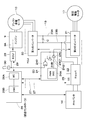
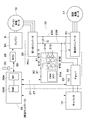
- FIG. 1 is a front view showing a hydraulic excavator according to a first embodiment. It is a block diagram which shows the structure of the electric system and hydraulic system of a hydraulic shovel. It is a block diagram which expands and shows the electric system in FIG. It is a block diagram which shows the structure of the electric system and hydraulic system of the hydraulic shovel by 2nd Embodiment.
- FIG. 5 is an enlarged block diagram illustrating a gate circuit and the like in FIG. 4.
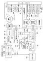
- It is a block diagram which shows the structure of the electric system and hydraulic system of the hydraulic shovel by 3rd Embodiment.
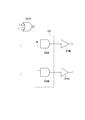
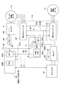
- It is a block diagram which shows the structure of the electric system and hydraulic system of the hydraulic shovel by 4th Embodiment. It is the same block diagram as FIG. 3 which shows the structure of the electric system by the 1st modification. It is the same block diagram as FIG. 3 which shows the structure of the electric system by the 2nd modification.
- FIG. 1 to 3 show a construction machine according to a first embodiment of the present invention.
- a hybrid hydraulic excavator 1 is a typical example of a hybrid construction machine.
- a hybrid hydraulic excavator 1 (hereinafter referred to as a hydraulic excavator 1) includes a self-propelled crawler-type lower traveling body 2, a slewing bearing device 3 provided on the lower traveling body 2, and the slewing bearing device 3.
- the upper revolving body 4 that is turnably mounted on the lower traveling body 2 and constitutes a vehicle body (base) together with the lower traveling body 2 and the earth and sand excavation work that is attached to the front side of the upper revolving body 4 so as to be able to move up and down. It is comprised including the working device 5 which performs etc.
- the lower traveling body 2 includes a track frame 2A, drive wheels 2B provided on the left and right sides of the track frame 2A, and drive wheels 2B on the left and right sides of the track frame 2A on the opposite side in the front and rear directions.
- An idler wheel 2C is provided, and a drive wheel 2B and a crawler belt 2D wound around the idler wheel 2C (both are shown only on the left side).
- the left and right drive wheels 2B are rotationally driven by left and right traveling hydraulic motors 2E and 2F (see FIG. 2), which are hydraulic motors (hydraulic actuators).
- the slewing bearing device 3 is attached to the upper side of the center portion of the track frame 2A.
- the working device 5 includes a boom 5A attached to the front side of a revolving frame 6 to be described later, an arm 5B attached to the tip of the boom 5A so as to be able to move up and down, and a pivot on the tip of the arm 5B.
- the bucket 5C is movably mounted, and includes a boom cylinder 5D, an arm cylinder 5E, and a bucket cylinder 5F, each of which includes a hydraulic cylinder (hydraulic actuator) that drives the bucket 5C.
- the upper revolving structure 4 includes a revolving frame 6 that forms a strong support structure.
- the swivel frame 6 is mounted on the lower traveling body 2 via the swivel bearing device 3 so as to be swivelable.
- the slewing bearing device 3 is attached to the lower surface side of the slewing frame 6.
- a cab 7, a counterweight 8, an engine 9, an assist power generation motor 10, a hydraulic pump 11, a power storage device 14, a turning device 15, a power conversion device 19 and the like are provided on the turning frame 6.
- the cab 7 is provided on the left front side of the revolving frame 6.
- a driver's seat on which an operator is seated is provided in the cab 7.
- a travel operation lever / pedal connected to a control valve 13 described later, a work operation lever, and the like are disposed.
- the counterweight 8 is attached to the rear end side of the revolving frame 6.
- the counterweight 8 balances the weight with the work device 5.
- the engine 9 is provided on the turning frame 6 between the cab 7 and the counterweight 8.
- the engine 9 is configured using, for example, a diesel engine, and is mounted as an internal combustion engine of the hybrid excavator 1 on the upper swing body 4 in a horizontally placed state extending in the left and right directions.
- An assist generator motor 10 and a hydraulic pump 11 described later are connected to the output side of the engine 9.
- the engine 9 is constituted by an electronically controlled engine, and for example, the fuel supply amount is variably controlled by a fuel injection device 9A such as an electronically controlled injection valve. That is, the fuel injection device 9A is an injection amount (fuel injection amount) of fuel injected into a cylinder (not shown) of the engine 9 based on a control signal output from an engine control unit (ECU) 28 described later. Is controlled variably. As a result, the engine 9 operates at a rotational speed corresponding to the driving operation of the operator, the operating state of the vehicle, and the like. Further, when an engine stop switch 30 described later is operated, the engine 9 stops the fuel injection of the fuel injection device 9A according to a command from the engine control unit 28, and the engine 9 stops.
- a fuel injection device 9A such as an electronically controlled injection valve. That is, the fuel injection device 9A is an injection amount (fuel injection amount) of fuel injected into a cylinder (not shown) of the engine 9 based on a control signal output from an engine control unit (ECU) 28 described later
- the assist generator motor 10 as a generator motor is connected to the engine 9.
- the assist power generation motor 10 is composed of, for example, a permanent magnet type synchronous motor, and generates electric power by being rotationally driven by the engine 9, or assists (assists) driving of the engine 9 by being supplied with electric power. is there. That is, the assist power generation motor 10 assists the drive of the engine 9 by being supplied with power through a function (generator function) for generating power by being rotationally driven by the engine 9 and DC buses 23A and 23B described later. Function (electric motor function).
- the electric power generated by the assist power generation motor 10 is supplied to a second inverter 21 and a chopper 22 to be described later via a first inverter 20 and DC buses 23A and 23B to be described later to drive the swing electric motor 17 and the power storage device 14. Is charged (storage).
- the assist power generation motor 10 is driven by electric power charged in the power storage device 14 (or regenerative electric power of the swing electric motor 17).
- a plurality of hydraulic pumps 11 and a hydraulic oil tank 12 constitute a hydraulic source.
- the hydraulic pump 11 is constituted by, for example, a swash plate type, an oblique axis type, or a radial piston type hydraulic pump, and is driven by the engine 9 and the assist power generation motor 10.
- the hydraulic pump 11 drives each hydraulic actuator, that is, the traveling hydraulic motors 2E and 2F of the lower traveling body 2, the boom cylinder 5D, the arm cylinder 5E, the bucket cylinder 5F of the working device 5, and the swing hydraulic motor 16 described later.
- the hydraulic oil in the hydraulic oil tank 12 is boosted and discharged toward a control valve 13 described later.
- the control valve 13 is provided on the turning frame 6.
- the control valve 13 includes a plurality of hydraulic control valves that control the hydraulic actuators (specifically, the traveling motors 2E and 2F, the cylinders 5D and 5E and 5F of the working device 5, and the swing hydraulic motor 16). ing.
- the control valve 13 switches supply and discharge of the pressure oil supplied from the hydraulic pump 11 according to a hydraulic signal or the like based on the operation of the operation lever / pedal for driving or the operation lever for work (discharge amount of pressure oil) And control the discharge direction).
- hydraulic oil (pressure oil) supplied from the hydraulic pump 11 to the control valve 13 is appropriately distributed to the respective hydraulic actuators 2E, 2F, 5D, 5E, 5F, 16 and these hydraulic actuators 2E, 2F, 5D, 5E, 5F, 16 can be driven (expanded, reduced, rotated).
- the power storage device 14 is provided on the turning frame 6.
- the power storage device 14 is connected to the assist power generation motor 10 and the swing electric motor 17 via a chopper 22, a first inverter 20, and a second inverter 21 described later.
- the power storage device 14 is configured using, for example, an electric double layer capacitor and stores electric charges. That is, the power storage device 14 charges (accumulates) the power generated by the assist power generation motor 10 and the power generation (regenerative power) generated during the turn deceleration by the swing electric motor 17, or the charged power is transferred to the assist power generation motor 10 and the turn.
- the electric motor 17 is discharged (powered).
- a battery such as a lithium ion battery can be used as the power storage device 14 in addition to the capacitor.
- the turning device 15 is provided on the upper turning body 4 (the turning frame 6).
- the turning device 15 is configured to turn the upper turning body 4 relative to the lower traveling body 2 by transmitting a rotational force to the turning bearing device 3.
- the turning device 15 is configured as a so-called hybrid turning device in which the turning hydraulic motor 16 and the turning electric motor 17 cooperate to drive the upper turning body 4 to turn.
- the turning device 15 includes a turning hydraulic motor 16 constituted by a hydraulic actuator such as a swash plate type hydraulic motor, a turning electric motor 17 as a turning electric motor constituted by an electric actuator such as an electric motor, and a turning hydraulic pressure.
- a speed reduction mechanism 18 that decelerates the rotation input from the motor 16 and / or the swing electric motor 17, and an output as a pinion that outputs the rotation decelerated by the speed reduction mechanism 18 to the swing bearing device 3 (inner teeth of the inner ring). And a shaft (not shown).
- the swing electric motor 17 rotates the upper swing body 4 in cooperation with the swing hydraulic motor 16.
- the swing electric motor 17 is configured by using, for example, a permanent magnet type synchronous motor, and is driven by power generated by the assist power generation motor 10 and power of the power storage device 14. Further, the turning electric motor 17 generates electric power by converting energy generated when the turning operation is decelerated into electric energy. That is, the turning electric motor 17 has a function (electric motor function) for turning the upper turning body 4 by being supplied with electric power via DC buses 23A and 23B, which will be described later, and a kinetic energy of the upper turning body 4 at the time of turning deceleration ( It has a function (generator function) for converting (rotational energy) into electric energy (regenerative power generation).
- the generated electric power (regenerative electric power) of the swing electric motor 17 is supplied to the first inverter 20 and the chopper 22 which will be described later via the second inverter 21 and the DC buses 23A and 23B which will be described later. Then, the power storage device 14 is charged (power storage).
- the electric system of the excavator 1 includes a first inverter 20 and a second inverter 21 described later in addition to the assist power generation motor 10, the power storage device 14, and the swing electric motor 17 described above.
- the first inverter 20, the second inverter 21, the chopper 22, the inverter controller 24, and the chopper controller 25 are collectively (unitized) as a power conversion device (PCU: power control unit) 19. It is mounted on the upper swing body 4.
- the first inverter 20 is used as an assist power generation inverter (assist power generation switching device).
- the first inverter 20 is electrically connected to the assist power generation motor 10.
- the first inverter 20 controls the driving of the assist power generation motor 10.
- the first inverter 20 is configured by using a plurality of (for example, six) switching elements made of, for example, transistors, insulated gate bipolar transistors (IGBTs), etc., and a pair of DC buses 23A and 23B, which will be described later. It is connected. Opening and closing of the switching element of the first inverter 20 is controlled by an inverter controller 24 described later.
- the first inverter 20 converts the power generated by the assist power generation motor 10 into DC power and supplies it to the DC buses 23A and 23B.
- the first inverter 20 when the assist generator motor 10 is driven, the first inverter 20 generates three-phase (U-phase, V-phase, W-phase) AC power from the DC power of the DC buses 23A, 23B, and the assist generator motor 10 To supply.
- the second inverter 21 is used as a turning inverter (turning switching device).
- the second inverter 21 is electrically connected to the swing electric motor 17.
- the second inverter 21 controls the driving of the swing electric motor 17.
- the second inverter 21 is configured by using a plurality of (for example, six) switching elements in substantially the same manner as the first inverter 20, and is connected to a pair of DC buses 23A and 23B described later. Yes. Opening and closing of the switching element of the second inverter 21 is controlled by an inverter controller 24 described later.
- the second inverter 21 During the turning drive of the swing electric motor 17, the second inverter 21 generates three-phase (U-phase, V-phase, W-phase) AC power from the DC power of the DC buses 23 ⁇ / b> A and 23 ⁇ / b> B and supplies it to the swing electric motor 17. To do. On the other hand, when the swing electric motor 17 is decelerated (regeneration), the second inverter 21 converts the regenerative power generated by the swing electric motor 17 into DC power and supplies it to the DC buses 23A and 23B.
- the chopper 22 has one end connected to the power storage device 14 and the other end connected to a pair of DC buses 23A and 23B.
- the chopper 22 and the inverters 20 and 21 are electrically connected to each other via a pair of DC buses 23A and 23B.
- the chopper 22 includes a plurality of (for example, two) switching elements made of, for example, an IGBT and a reactor.
- the chopper 22 is controlled to be opened and closed by a chopper controller 25 described later.
- step-down chopper When the power storage device 14 is charged, the chopper 22 functions as a step-down circuit (step-down chopper), and for example, steps down a DC voltage supplied from the DC buses 23A and 23B and supplies the voltage to the power storage device 14.
- step-down chopper step-down circuit
- the chopper 22 functions as a booster circuit (boost chopper), boosts the DC voltage supplied from the power storage device 14 and supplies the boosted DC voltage to the DC buses 23
- the inverters 20 and 21 and the chopper 22 are connected to each other through a pair of DC buses 23A and 23B on the positive electrode side (plus side) and the negative electrode side (minus side).
- a smoothing capacitor C is connected to the DC buses 23A and 23B in order to stabilize the voltage of the DC buses 23A and 23B. For example, a predetermined DC voltage of about several hundred volts is applied to the DC buses 23A and 23B.
- the inverter controller 24 is used as a controller (control device). That is, the inverter controller 24 controls the inverters 20 and 21.
- the inverter controller 24 is composed of, for example, a microcomputer or the like, and uses various signals such as operation command signals to control commands for the first inverter 20 and the second inverter 21 (for example, the inverters 20 and 21). A gate signal for controlling opening and closing of the switching element), and driving control (rotational speed control) of the motors 10 and 17 is performed.
- the configuration of the inverter controller 24 will be described in detail later.
- the chopper controller 25 is used as a controller (control device). That is, the chopper controller 25 controls the chopper 22.
- the chopper controller 25 is constituted by, for example, a microcomputer and generates a control command (for example, a gate signal for controlling opening / closing of the switching element) to the chopper 22 using various signals such as an operation command signal. Then, control is performed such that the voltages of the DC buses 23A and 23B are held near a predetermined constant value.
- the inverter controller 24 and the chopper controller 25 are connected to an integrated controller (main control unit) 26 including a malfunction monitoring / malfunction processing control section (MC) 26A, an energy management control section (EMC) 26B, etc. 27 are electrically connected to each other via a terminal 27 to form a CAN (Control Area Network).
- the integrated controller 26 is also composed of a microcomputer or the like, generates control commands for the inverter controller 24, the chopper controller 25, and the like, controls the drive of the assist power generation motor 10, the swing electric motor 17, the malfunction monitoring of the electric system, and energy management. Etc. are controlled.
- the malfunction monitoring / malfunction processing control unit 26A controls malfunction monitoring of the electric system. Specifically, the malfunction monitoring / synchronization processing control unit 26A has experienced malfunctions, abnormalities, warnings, etc. in the electric system such as the power conversion device 19, the assist power generation motor 10, the swing electric motor 17, and the power storage device 14. When it is determined that a malfunction has occurred, an electric system malfunction signal (a signal indicating malfunction) that is a signal to that effect is output to the inverter controller 24 (or gate 24D). To do.
- the power storage command of the power storage device 14 that increases or decreases depending on the difference between the energy consumed by the swing electric motor 17 during acceleration and the energy regenerated during deceleration is supplied to the assist power generation motor 10 as a power generation command or an assist command.
- the output is controlled to keep within a predetermined range.
- the integrated controller 26 is electrically connected to an engine control unit 28 called ECU via a communication line 29.
- the engine control unit 28 controls the engine 9 (rotational speed control or the like), and is connected to, for example, a fuel injection device 9A of the engine 9.
- the engine control unit 28 variably controls the fuel injection amount (fuel supply amount) by the fuel injection device 9A into the cylinder of the engine 9 so that the engine control unit 28 can rotate at a rotational speed corresponding to the driving operation of the operator or the operating state of the vehicle.
- the engine 9 is operated.
- the engine control unit 28 controls the fuel injection amount of the fuel injection device 9A based on, for example, a command from an engine speed instruction dial (not shown) operated by an operator, a command from the integrated controller 26, and the like. Do.
- the engine stop switch 30 is a switch for stopping the engine 9.
- the engine stop switch 30 is connected to the engine control unit 28 and the inverter controller 24 (or the gate 24D).
- the engine stop switch 30 is configured to shut off the gate signal output from the inverter controller 24 in addition to stopping the engine 9 when operated. That is, the engine stop switch 30 is configured as a both stop switch that stops both the engine 9 and the assist generator motor 10 (and the swing electric motor 17).
- the gate signal is cut off by the engine stop switch 30 regardless of the PWM signal generated by the inverter controller 24 (a signal corresponding to the switching element open / close ratio). That is, the gate signal is cut off by the engine stop switch 30 regardless of the PWM signal for the first inverter 20 and the PWM signal for the second inverter 21 generated by the inverter controller 24.
- the inverter controller 24 outputs a gate signal for controlling opening and closing of the switching element of the first inverter 20 and the switching element of the second inverter 21 to control the assist generator motor 10 and the swing electric motor 17 ( For example, the rotational speed is controlled).
- the inverter controller 24 generates a PWM signal generation circuit (PWMSGC) 24A as a PWM signal generation unit that generates a PWM signal for the switching element of the first inverter 20 and a PWM signal for the switching element of the second inverter 21.
- PWMSGC PWM signal generation circuit
- a first gate signal generation circuit 24B as a gate signal generation unit that outputs a gate signal to the first inverter 20 based on the PWM signal generated by the PWM signal generation circuit 24A, and a PWM signal generation circuit 24A.
- a second gate signal generation circuit 24C as a gate signal generation unit that outputs a gate signal to the second inverter 21 based on the PWM signal thus generated.
- the inverter controller 24 is provided with an OR gate 24D.
- the OR gate 24D generates a first gate signal when an at least one of an engine stop switch signal (signal indicating stop), which will be described later, and an electric system malfunction signal (signal indicating malfunction) are input. This is for outputting a signal to stop the output of the gate signal to the circuit 24B and the second gate signal generation circuit 24C.
- the inverter controller 24 receives a torque command, a power generation command or an assist command from the integrated controller 26, and outputs a three-phase PWM signal from the PWM signal generation circuit 24A according to the command.
- Each of the gate signal generation circuits 24B and 24C is based on the three-phase PWM signal output from the PWM signal generation circuit 24A (PWM signal corresponding to the open / close ratio of each switching element).
- Gate signals are output to the upper and lower arms of the three phases and the upper and lower arms of the three phases of the second inverter 21, respectively.
- the switching element in the 1st inverter 20 and the switching element in the 2nd inverter 21 open and close based on each gate signal, and a three-phase alternating current is produced
- the assist power generation motor 10 and the swing electric motor 17 are driven with the commanded torque.
- an engine stop switch signal (a signal indicating the stop) is output from the engine stop switch 30, and the engine stop switch signal is output from the engine control unit. 28.
- an engine stop switch signal stop signal
- the engine control unit 28 outputs a signal for stopping fuel injection to the fuel injection device 9A of the engine 9. Thereby, the fuel injection of the fuel injection device 9A is stopped, and the engine 9 is stopped.
- the engine stop switch signal (stop signal) output from the engine stop switch 30 is input not only to the engine control unit 28 but also to the inverter controller 24 (or the gate 24D thereof).
- the inverter controller 24 receives the first inverter 20 and the first inverter 20 from the gate signal generation circuits 24B and 24C. The gate signal output to the inverter 21 of 2 is cut off, and the electric system is stopped.
- the inverter controller 24 (or the gate 24D thereof) also receives the electric system malfunction signal (signal indicating malfunction) from the integrated controller 26. That is, the malfunction monitoring / malfunction processing control unit 26A of the integrated controller 26 outputs an electric system malfunction signal, which is a signal to that effect, when the malfunction condition, abnormality, warning, or the like occurs in the electric system. (Or OR gate 24D).
- the energy management control unit 26B of the integrated controller 26 generates an electric system malfunction signal (for example, malfunction monitoring / stabilization) that becomes a signal to that effect when the amount of power stored in the power storage device 14 falls outside a predetermined range. Output to the inverter controller 24 (or its gate 24D) via the processing control unit 26A.
- the inverter controller 24 receives the first inverter 20 and the first inverter 20 from the gate signal generation circuits 24B and 24C even when an electric system malfunction signal (a signal indicating malfunction) is input from the integrated controller 26.
- the gate signal output to the inverter 21 of 2 is cut off, and the electric system is stopped.
- the inverter controller 24 includes an engine stop switch signal from the engine stop switch 30 (stop signal) and an electric system malfunction signal from the integrated controller 26 (malfunction signal).
- stop signal an electric system malfunction signal from the integrated controller 26
- the gate signals output from the gate signal generation circuits 24B and 24C to the first inverter 20 and the second inverter 21 are cut off, and the electric system is stopped.
- the gate signal generation circuits 24B and 24C of the inverter controller 24 are controlled by an inhibition terminal (inhibit terminal) 24B1, which stops the output of the gate signal based on the operation of the engine stop switch 30 and / or a command from the integrated controller 26. 24C1 is provided.
- An engine stop switch signal from the engine stop switch 30 and an electric system malfunction signal from the malfunction monitoring / malfunction processing control unit 26A of the integrated controller 26 are selectively input to the inhibition terminals 24B1 and 24C1.
- the inverter controller 24 includes a two-input OR gate 24D.
- One input side of the OR gate 24D is connected to the engine stop switch 30, and the other input side is connected to the malfunction monitoring / malfunction processing control unit 26A of the integrated controller 26.
- the output side of the OR gate 24D is connected to the inhibition terminals 24B1 and 24C1 of the gate signal generation circuits 24B and 24C.
- the engine stop switch signal is inverted and input to one input side of the OR gate 24D
- the electric system malfunction signal is inverted and input to the other input side of the OR gate 24D.
- the calculated output is inverted and output. In other words, it is configured as an inverting input NOR gate.
- the engine stop switch 30 outputs 1 when it is not operated (OFF), and outputs 0 when operated by an operator or the like to stop the engine 9 (turns ON).
- the malfunction monitoring / malfunction processing control unit 26A of the integrated controller 26 outputs 1 when normal, and outputs 0 when determined to be malfunctioning.
- the OR gate 24D changes its output (inverted output) from the high level (1) to the low level (0). (The output becomes low level).
- the output (inverted output) of the OR gate 24D is input to the inhibition terminals 24B1 and 24C1 of the gate signal generation circuits 24B and 24C.
- the gate signal generation circuits 24B and 24C when the signal levels of the inhibition terminals 24B1 and 24C1 change from the high level (1) to the low level (0), the gate signals to the first inverter 20 and the second inverter 21. Stop the output of.
- the gate signal output to the first inverter 20 and the second inverter 21 may be cut off. it can. As a result, the assist power generation motor 10 and the swing electric motor 17 can be stopped.
- the engine stop switch 30 and the integrated controller 26 are directly connected to the inhibition terminals 24B1 and 24C1 of the gate signal generation circuits 24B and 24C via the OR gate 24D. It is connected. Therefore, based on the electrical signals (engine stop switch signal, electric system malfunction signal) output from the engine stop switch 30 and / or the integrated controller 26 without using software installed in the inverter controller 24. The gate signal output from the gate signal generation circuits 24B and 24C can be stopped.
- the operation of the engine stop switch 30 causes the gate signal to be output to the inhibition terminals 24B1 and 24C1 of the gate signal generation circuits 24B and 24C via the OR gate 24D.
- a stop signal is input.
- the assist power generation motor 10 and the swing electric motor 17 can be quickly stopped together with the stop of the engine 9.
- the hydraulic excavator 1 according to the first embodiment has the above-described configuration, and the operation thereof will be described next.
- the operator gets into the cab 7 and sits in the driver's seat. In this state, the operator operates the operation lever / pedal for traveling to supply pressure oil from the control valve 13 to the traveling motors 2E and 2F of the lower traveling body 2, and the left and right drive wheels 2B are moved.
- the hydraulic excavator 1 can be moved forward or backward by driving. Further, the operator can perform excavation work of earth and sand by turning the upper swing body 4 or moving the working device 5 up and down by operating the operation lever.
- an engine stop switch signal (a signal indicating stop) is sent from the engine stop switch 30 to the engine control unit 28. It is input to the inverter controller 24 (or its gate 24D). Thereby, the fuel injection from the fuel injection device 9A of the engine 9 is stopped, and the engine 9 is stopped. In addition, the gate signal output from the gate signal generation circuits 24B and 24C of the inverter controller 24 is stopped, and the assist power generation motor 10 and the swing electric motor 17 are also stopped.
- the inverter controller 24 when the engine stop switch 30 is operated, in addition to stopping the engine 9, the inverter controller 24 outputs to the first inverter 20 and the second inverter 21. Interrupts the gate signal. Therefore, the assist power generation motor 10 and the swing electric motor 17 can be stopped together with the stop of the engine 9 based on the operation of the engine stop switch 30.
- the engine stop switch 30 is operated to operate the engine 9 and the assist power generation.
- the hydraulic pump 11 driven by the motor 10 can be quickly stopped.
- the turning electric motor 17 can also be stopped, and the turning device 15 can be quickly stopped. As a result, the excavator 1 can be stopped immediately.
- the gate signal is cut off regardless of the PWM signal generated by the inverter controller 24. That is, even if the PWM signal is generated by the PWM signal generation circuit 24A of the inverter controller 24 based on the command of the integrated controller 26, etc., it is based on the electrical signal (engine stop switch signal) output from the engine stop switch 30.
- the gate signal output from the gate signal generation circuits 24B and 24C is stopped. For this reason, even if the inverter controller 24 generates a PWM signal indicating that the assist generator motor 10 and the swing electric motor 17 continue to rotate, the gate signal is blocked, and the assist generator motor 10 and the swing electric motor 17 are It can be stopped reliably.
- the engine stop switch 30 when the engine stop switch 30 is operated to output an engine stop switch signal (a signal indicating the stop) from the engine stop switch 30, the engine stop switch signal is It is directly input to the inhibition terminals 24B1 and 24C1 of the gate signal generation circuits 24B and 24C (via the OR gate 24D), and the gate signal output by the gate signal generation circuits 24B and 24C can be stopped.
- the gate signal output from the gate signal generation circuits 24B and 24C to the first inverter 20 and the second inverter 21 can be stopped, and the assist generator motor 10 and the swing electric motor 17 can be stopped reliably. it can.
- FIGS. 4 and 5 show a construction machine according to a second embodiment of the present invention.
- a feature of the second embodiment resides in that a gate circuit for cutting off the PWM signal is provided between the PWM signal generation unit and the gate signal generation unit.
- the same components as those in the first embodiment described above are denoted by the same reference numerals, and description thereof is omitted.
- an inverter controller 31 is an inverter controller used in the second embodiment instead of the inverter controller 24 of the first embodiment.
- the inverter controller 31 sends a gate signal to the first inverter 20 based on the PWM signal generation circuit 31A similar to the PWM signal generation circuit 24A of the first embodiment and the PWM signal generated by the PWM signal generation circuit 31A.
- the circuit includes a second gate signal generation circuit 31C and a gate circuit 32 described later.
- the inverter controller 31 is provided with an OR gate 31D which is different from the OR gate 24D of the first embodiment in that it is not connected to the inhibition terminals 24B1 and 24C1 of the gate signal generation circuits 24B and 24C. .
- the OR gate 31D is connected to the gate circuit 32.
- the gate circuit 32 is provided between the PWM signal generation circuit 31A and the gate signal generation circuits 31B and 31C.
- the gate circuit 32 blocks the input of the PWM signal to each of the gate signal generation circuits 31B and 31C based on the operation of the engine stop switch 30.
- the engine stop switch signal from the engine stop switch 30 and the electric system malfunction signal from the malfunction monitoring / malfunction processing control unit 26A of the integrated controller 26 are selectively input to the gate circuit 32. Therefore, the input side of the gate circuit 32 is connected to the output side of the OR gate 31D, and the output of the OR gate 31D is input to the gate circuit 32.
- the number of PWM signals input from the PWM signal generation circuit 31A to the gate circuit 32 is six, and the gate circuit 32 includes six 2-input AND gates 32A and 32B. Since the six AND gates 32A and 32B have the same configuration, in FIG. 5, two AND gates, one AND gate 32A for the assist power generation motor and one AND gate 32B for the swing electric motor. 32A and 32B are shown.
- the gate circuit 32 one input side of the AND gates 32A and 32B is connected to the PWM signal generation circuit 31A. That is, one PWM signal is input to one input side of the AND gates 32A and 32B.
- the other input side of the AND gates 32A and 32B is connected to the output side of the OR gate 31D. That is, the output (inverted output) of the OR gate 31D is input to the other input side of the AND gates 32A and 32B.
- the engine stop switch 30 outputs 1 when it is not operated (OFF), and outputs 0 when it is operated (turned ON) by an operator or the like to stop the engine 9.
- the malfunction monitoring / malfunction processing control unit 26A of the integrated controller 26 outputs 1 when normal, and outputs 0 when determined to be malfunctioning. Accordingly, when at least one of the engine stop switch signal and the electric system malfunction signal is switched from 1 to 0, the output (inverted output) of the OR gate 31D changes from the high level (1) to the low level (0). ) And one input of the AND gates 32A and 32B is turned OFF (0).
- the PWM signal input from the PWM signal generation circuit 31A to each of the gate signal generation circuits 31B and 31C is cut off, and the output of the gate signal of each of the gate signal generation circuits 31B and 31C is stopped.
- the assist power generation motor 10 and the swing electric motor 17 can be stopped.
- an electrical signal (engine stop switch signal, electric system malfunction) output from the engine stop switch 30 and / or the integrated controller 26 without using software installed in the inverter controller 31.
- the gate circuit 32 can prevent the PWM signal generated by the PWM signal generation circuit 31A from being input to the gate signal generation circuits 31B and 31C.
- the operation of the engine stop switch 30 causes the gate signal generation circuits 31B and 31C to be supplied to the AND gates 32A and 32B of the gate circuit 32 via the OR gate 31D.
- a signal for stopping the input of the PWM signal to is input.
- the assist power generation motor 10 and the swing electric motor 17 can be quickly stopped together with the stop of the engine 9.
- the second embodiment is configured to block the PWM signal using the gate circuit 32 as described above, and the basic operation is not particularly different from that according to the first embodiment described above. .
- the engine stop switch signal (a signal indicating a stop) is output from the engine stop switch 30 by operating the engine stop switch 30 by operating the engine stop switch 30
- the engine stop switch signal is The input of the PWM signal to the gate signal generation circuits 31B and 31C can be blocked by being input to the gate circuit 32 (and the AND gates 32A and 32B thereof) via the OR gate 24D.
- the output of the gate signal to each of the first inverter 20 and the second inverter 21 from each gate signal generation circuit 31B, 31C can be stopped, and the assist power generation motor 10 and the swing electric motor 17 can be stopped reliably. Can do.
- FIG. 6 shows a construction machine according to a third embodiment of the present invention.
- a feature of the third embodiment is that an OR gate is provided in a controller (integrated controller) different from the inverter controller, and an engine stop switch is connected to the OR gate of the other controller. Note that in the third embodiment, the same components as those in the first embodiment and the second embodiment described above are denoted by the same reference numerals, and description thereof is omitted.
- an inverter controller 41 is an inverter controller used in the third embodiment in place of the inverter controller 24 of the first embodiment.
- the inverter controller 41 includes a PWM signal generation circuit 41A similar to the PWM signal generation circuit 24A of the first embodiment, and the inhibition terminals 41B1, similarly to the gate signal generation circuits 24B and 24C of the first embodiment. Gate signal generation circuits 41B and 41C having 41C1 are included.
- the third embodiment is different from the inverter controller 24 of the first embodiment in that the inverter controller 41 does not have an OR gate (the inverter controller 41 is not provided with an OR gate).
- the integrated controller 42 is an integrated controller used in the third embodiment in place of the integrated controller 26 of the first embodiment.
- the integrated controller 42 includes the same malfunction monitoring / malfunction processing control unit 42A as in the first embodiment and an energy management control unit 42B similar to that in the first embodiment.
- the integrated controller 42 is provided with an OR gate 43 described later.
- the engine stop switch 30 is connected to the integrated controller 42 (or the gate 43 thereof) with the configuration in which the integrated controller 42 has the OR gate 43 (the OR gate 43 is provided in the integrated controller 42). Has been.
- the OR gate 43 receives the engine stop switch signal from the engine stop switch 30 and the electric system malfunction signal from the malfunction monitoring / malfunction processing control unit 42A of the integrated controller 42. As with the OR gate 24D of the first embodiment, the OR gate 43 receives at least one of an engine stop switch signal (stop signal) and an electric system malfunction signal (malfunction signal). Then, a signal for stopping the output of the gate signal is output to each of the gate signal generation circuits 41B and 41C.
- One input side of the OR gate 43 is connected to the engine stop switch 30, and the other input side is connected to the malfunction monitoring / malfunction processing control unit 42A of the integrated controller 42.
- the output side of the OR gate 43 is connected to the inhibition terminals 41B1 and 41C1 of the gate signal generation circuits 41B and 41C.
- the engine stop switch signal is inverted and input to one input side of the OR gate 43, and the electric system malfunction signal is inverted and input to the other input side of the OR gate 43.
- the calculated output is inverted and output. In other words, it is configured as an inverting input NOR gate.
- the engine stop switch 30 outputs 1 when it is not operated (OFF), and outputs 0 when operated by an operator or the like to stop the engine 9 (turns ON).
- the malfunction monitoring / malfunction processing control unit 42A of the integrated controller 42 outputs 1 when normal, and outputs 0 when determined to be malfunctioning.
- the OR gate 43 changes its output (inverted output) from the high level (1) to the low level (0). (The output becomes low level).
- the output of the OR gate 43 (inverted output) is input to the inhibition terminals 41B1 and 41C1 of the gate signal generation circuits 41B and 41C.
- the gate signal generation circuits 41B and 41C are connected to the first inverter 20 and the second inverter 21. Stop the output of. Thereby, the gate signal output to the 1st inverter 20 and the 2nd inverter 21 can be interrupted
- an electrical signal (engine stop switch signal, electric system malfunction) output from the engine stop switch 30 and / or the integrated controller 42 without using software installed in the inverter controller 41.
- Signal from the gate signal generation circuits 41B and 41C can be stopped.
- the gate signal is output to the inhibition terminals 41B1 and 41C1 of the gate signal generation circuits 41B and 41C through the OR gate 43 by the operation of the engine stop switch 30.
- a stop signal is input.
- the assist power generation motor 10 and the swing electric motor 17 can be quickly stopped together with the stop of the engine 9.
- the third embodiment is configured such that the gate signal is cut off via the OR gate 43 as described above, and there is no particular difference in basic operation from that according to the first embodiment described above.
- the engine stop switch 30 can be connected to the OR gate 43 of the integrated controller 42. Thereby, the freedom degree of the wiring of the engine stop switch 30 can be improved.
- the case where the output of the OR gate 43 is input to the inhibition terminals 41B1 and 41C1 of the gate signal generation circuits 41B and 41C has been described as an example.
- the present invention is not limited to this, and the gate circuit 32 of the second embodiment is provided between the PWM signal generation circuit 41A and each of the gate signal generation circuits 41B and 41C, as indicated by a broken line in FIG.
- the same gate circuit 51 may be provided, and the output of the OR gate 43 may be input to an AND gate (not shown) of the gate circuit 51.
- FIG. 7 shows a construction machine according to a fourth embodiment of the present invention.
- a feature of the fourth embodiment is that a relay circuit is provided between the gate signal generation unit and the assist power generation inverter. Note that in the fourth embodiment, the same components as those in the first to third embodiments described above are denoted by the same reference numerals, and description thereof is omitted.
- the inverter controller 61 is an inverter controller used in the fourth embodiment instead of the inverter controller 24 of the first embodiment.
- the inverter controller 61 sends a gate signal to the first inverter 20 based on the PWM signal generation circuit 61A similar to the PWM signal generation circuit 24A of the first embodiment and the PWM signal generated by the PWM signal generation circuit 61A.
- a second gate signal generation circuit 61C a second gate signal generation circuit 61C.
- the inverter controller 61 is provided with an OR gate 61D which is different from the OR gate 24D of the first embodiment in that it is not connected to the inhibition terminals 24B1 and 24C1 of the gate signal generation circuits 24B and 24C. .
- the OR gate 61D is connected to a relay circuit 62 described later.
- the relay circuit 62 is provided between the gate signal generation circuits 61B and 61C and the first inverter 20 and the second inverter 21.
- the relay circuit 62 cuts off the connection between the gate signal generation circuits 61B and 61C and the first inverter 20 and the second inverter 21 based on the operation of the engine stop switch 30.
- the engine stop switch signal from the engine stop switch 30 and the electric system malfunction signal from the malfunction monitoring / malfunction processing control unit 26A of the integrated controller 26 are selectively input to the relay circuit 62.
- the input side of the relay circuit 62 is connected to the output side of the OR gate 61D, and the output of the OR gate 61D is input to the relay circuit 62.
- the engine stop switch 30 outputs 1 when it is not operated (OFF), and outputs 0 when it is operated (turned ON) by an operator or the like to stop the engine 9.
- the malfunction monitoring / malfunction processing control unit 26A of the integrated controller 26 outputs 1 when normal, and outputs 0 when determined to be malfunctioning. Accordingly, when at least one of the engine stop switch signal and the electric system malfunction signal is switched from 1 to 0, the output (inverted output) of the OR gate 61D changes from the high level (1) to the low level (0). ) And output to the relay circuit 62.
- the relay circuit 62 the relay is activated as the input is changed from the high level (1) to the low level (0), and the gate signal generation circuits 61B and 61C, the first inverter 20, and the second inverter 20 The connection with the inverter 21 is interrupted. Thereby, the gate signal output from each gate signal generation circuit 61B, 61C is no longer input into the 1st inverter 20 and the 2nd inverter 21, and the assist electric power generation motor 10 and the turning electric motor 17 stop.
- an electrical signal (engine stop switch signal, electric system malfunction) output from the engine stop switch 30 and / or the integrated controller 26 without using software installed in the inverter controller 61.
- Signal can be prevented from being input to the first inverter 20 and the second inverter 21 from the gate signal generation circuits 61B and 61C.
- the operation of the engine stop switch 30 causes the gates for the first inverter 20 and the second inverter 21 to be connected to the relay circuit 62 via the OR gate 61D.
- a signal for stopping signal input is input.
- the assist power generation motor 10 and the swing electric motor 17 can be quickly stopped together with the stop of the engine 9.
- the fourth embodiment is configured such that the gate signal is cut off using the relay circuit 62 as described above, and the basic operation is not particularly different from that according to the first embodiment described above. .
- the engine stop switch signal (a signal indicating a stop) is output from the engine stop switch 30 by operating the engine stop switch 30
- the engine stop switch signal is The gate signal input to the first inverter 20 and the second inverter 21 can be cut off by being input to the relay circuit 62 (through the OR gate 61D).
- the assist electric power generation motor 10 and the turning electric motor 17 can be stopped reliably.
- the case where the engine stop switch 30 and the malfunction monitoring / malfunction processing control unit 26A of the integrated controller 26 are connected to the OR gate 24D has been described as an example. More specifically, the engine stop switch signal is inverted and input to one input side of the OR gate 24D, the electric system malfunction signal is inverted and input to the other input side of the OR gate 24D, and OR operation is performed from the OR gate 24D.
- the case where the output is inverted and output (when configured as an inverted input NOR gate) is described as an example.
- the present invention is not limited to this, and the engine stop switch 30 and the malfunction monitoring / malfunction processing control unit 26A of the integrated controller 26 are connected to the AND gate 71 as in the first modification shown in FIG. It is good also as a structure.
- the second embodiment, the third embodiment, and the fourth embodiment are connected to the OR gate 24D.
- the engine stop switch 30 and the malfunction monitoring / malfunction processing control unit 26A of the integrated controller 26 are connected to the OR gate 31D, and the OR gate 31D is connected to the AND gates 32A and 32B of the gate circuit 32.
- the present invention is not limited to this.
- an OR gate may be omitted as in the second modification shown in FIG. That is, the engine stop switch 30 and the malfunction monitoring / malfunction processing control unit 26A of the integrated controller 26 may be connected to the AND gates 81A, 81B, 81C, 81D constituting the gate circuit 81, respectively.
- the AND gates 81A and 81B connected to the engine stop switch 30, and the AND gates 81C and 81D connected to the malfunction monitoring / malfunction processing control unit 26A of the integrated controller 26, the PWM signal generation circuit 31A, and each A configuration may be employed in which the gate signal generation circuits 31B and 31C are provided in series. The same applies to the third embodiment.
- the relay circuit 62 is provided between the gate signal generation circuits 61B and 61C and the first inverter 20 and the second inverter 21 has been described as an example.
- the present invention is not limited thereto, and for example, a relay circuit may be provided between the PWM signal generation circuit (PWM signal generation unit) and the gate signal generation circuit (gate signal generation unit).
- the inverter controller 61 is provided in the OR gate 61D (the inverter controller 61 has the OR gate 61D).
- the present invention is not limited to this.
- an engine stop switch is provided in a part different from the inverter controller, such as a controller (for example, an integrated controller) different from the inverter controller.
- a controller for example, an integrated controller
- the AND gate 71 connected to the engine stop switch 30 may be provided in a part (for example, the integrated controller 26) different from the inverter controller 24.
- the gate signal output from the inverter controller 24, 31, 41, 61 is cut off based on at least one signal.
- the gate signal output from the inverter controller may be blocked based on only the engine stop switch signal (stop signal).
- the gate signal output from the inverter controller may be cut off.
- the assist generator motor 10 and the swing electric motor 17 are based on the engine stop switch signal from the engine stop switch 30 (and / or the electric system malfunction signal from the integrated controller 26). As an example, a case in which both are stopped is described. However, the present invention is not limited to this, and for example, only the assist generator motor (generator motor) may be stopped based on an engine stop switch signal (and / or a signal from the controller) from the engine stop switch. .
- the turning device 15 is a hybrid turning device constituted by the turning hydraulic motor 16 and the turning electric motor 17 has been described as an example.
- the present invention is not limited to this.
- the turning device may be an electric turning device (without a hydraulic motor) configured by a turning electric motor (electric motor) alone.
- the hydraulic excavator 1 has been described as an example of the construction machine.
- the present invention is not limited to this, and can be widely applied to hybrid construction machines including various work vehicles, work machines, and the like such as wheel loaders, hydraulic cranes, forklifts, and the like.
Landscapes
- Engineering & Computer Science (AREA)
- Mechanical Engineering (AREA)
- General Engineering & Computer Science (AREA)
- Automation & Control Theory (AREA)
- Transportation (AREA)
- Chemical & Material Sciences (AREA)
- Combustion & Propulsion (AREA)
- Mining & Mineral Resources (AREA)
- Civil Engineering (AREA)
- Structural Engineering (AREA)
- Operation Control Of Excavators (AREA)
- Control Of Vehicle Engines Or Engines For Specific Uses (AREA)
Abstract
L'invention porte sur un dispositif de commande d'onduleur (24) pour commander un premier onduleur (20) relié à un moteur-générateur d'assistance (10), qui est configuré de manière à comprendre un premier circuit de génération du signal de grille (24B) pour émettre un signal de grille vers le premier onduleur (20). Le premier circuit de génération du signal de grille (24B) comporte un terminal de suppression (24B1), et le terminal de suppression (24B1) est connecté à un commutateur d'arrêt de moteur (30). Lorsque le commutateur d'arrêt de moteur (30) est actionné, un moteur (9) est arrêté, la sortie d'un signal de grille provenant du premier circuit de génération du signal de grille (24B) pour le premier onduleur (20) est interrompue, et le moteur-générateur d'assistance (10) est arrêté.
Applications Claiming Priority (2)
| Application Number | Priority Date | Filing Date | Title |
|---|---|---|---|
| JP2014030589A JP2015155606A (ja) | 2014-02-20 | 2014-02-20 | 建設機械 |
| JP2014-030589 | 2014-02-20 |
Publications (1)
| Publication Number | Publication Date |
|---|---|
| WO2015125601A1 true WO2015125601A1 (fr) | 2015-08-27 |
Family
ID=53878112
Family Applications (1)
| Application Number | Title | Priority Date | Filing Date |
|---|---|---|---|
| PCT/JP2015/052974 Ceased WO2015125601A1 (fr) | 2014-02-20 | 2015-02-03 | Engin de chantier |
Country Status (2)
| Country | Link |
|---|---|
| JP (1) | JP2015155606A (fr) |
| WO (1) | WO2015125601A1 (fr) |
Cited By (3)
| Publication number | Priority date | Publication date | Assignee | Title |
|---|---|---|---|---|
| WO2017199546A1 (fr) * | 2016-05-18 | 2017-11-23 | 日立建機株式会社 | Engin de chantier |
| CN108515842A (zh) * | 2018-04-13 | 2018-09-11 | 河南科技大学 | 双电机电动拖拉机pto控制系统 |
| CN115700993A (zh) * | 2021-07-23 | 2023-02-07 | 意法半导体国际有限公司 | 电机/控制器认证系统 |
Citations (2)
| Publication number | Priority date | Publication date | Assignee | Title |
|---|---|---|---|---|
| JP2010200458A (ja) * | 2009-02-24 | 2010-09-09 | Sumitomo Heavy Ind Ltd | ハイブリッド型建設機械 |
| JP2012082607A (ja) * | 2010-10-08 | 2012-04-26 | Hitachi Constr Mach Co Ltd | ハイブリッド式建設機械 |
Family Cites Families (4)
| Publication number | Priority date | Publication date | Assignee | Title |
|---|---|---|---|---|
| JP2008075365A (ja) * | 2006-09-22 | 2008-04-03 | Shin Caterpillar Mitsubishi Ltd | 作業機械における制御システム |
| JP5101405B2 (ja) * | 2008-06-20 | 2012-12-19 | 住友重機械工業株式会社 | 旋回駆動制御装置及びこれを含む建設機械 |
| JP5421074B2 (ja) * | 2008-11-10 | 2014-02-19 | 住友重機械工業株式会社 | ハイブリッド型建設機械 |
| JP5420267B2 (ja) * | 2009-02-17 | 2014-02-19 | 住友重機械工業株式会社 | ハイブリッド型作業機械およびハイブリッド型作業機械の制御方法 |
-
2014
- 2014-02-20 JP JP2014030589A patent/JP2015155606A/ja active Pending
-
2015
- 2015-02-03 WO PCT/JP2015/052974 patent/WO2015125601A1/fr not_active Ceased
Patent Citations (2)
| Publication number | Priority date | Publication date | Assignee | Title |
|---|---|---|---|---|
| JP2010200458A (ja) * | 2009-02-24 | 2010-09-09 | Sumitomo Heavy Ind Ltd | ハイブリッド型建設機械 |
| JP2012082607A (ja) * | 2010-10-08 | 2012-04-26 | Hitachi Constr Mach Co Ltd | ハイブリッド式建設機械 |
Cited By (8)
| Publication number | Priority date | Publication date | Assignee | Title |
|---|---|---|---|---|
| WO2017199546A1 (fr) * | 2016-05-18 | 2017-11-23 | 日立建機株式会社 | Engin de chantier |
| JP2017206868A (ja) * | 2016-05-18 | 2017-11-24 | 日立建機株式会社 | 建設機械 |
| CN108699809A (zh) * | 2016-05-18 | 2018-10-23 | 日立建机株式会社 | 工程机械 |
| CN108699809B (zh) * | 2016-05-18 | 2020-12-25 | 日立建机株式会社 | 工程机械 |
| US11220803B2 (en) | 2016-05-18 | 2022-01-11 | Hitachi Construction Machinery Co., Ltd. | Construction machine |
| CN108515842A (zh) * | 2018-04-13 | 2018-09-11 | 河南科技大学 | 双电机电动拖拉机pto控制系统 |
| CN108515842B (zh) * | 2018-04-13 | 2020-07-31 | 河南科技大学 | 双电机电动拖拉机pto控制系统 |
| CN115700993A (zh) * | 2021-07-23 | 2023-02-07 | 意法半导体国际有限公司 | 电机/控制器认证系统 |
Also Published As
| Publication number | Publication date |
|---|---|
| JP2015155606A (ja) | 2015-08-27 |
Similar Documents
| Publication | Publication Date | Title |
|---|---|---|
| KR101853147B1 (ko) | 하이브리드식 건설 기계 | |
| CN103443363B (zh) | 混合动力式工程机械及用于该工程机械的辅助控制装置 | |
| JP6657278B2 (ja) | ショベル | |
| EP2626474B1 (fr) | Machine de construction hybride avec controle de freins de la superstructure | |
| CN103328731B (zh) | 具有回转体的施工机械 | |
| KR101925226B1 (ko) | 건설 기계 | |
| JP6707065B2 (ja) | 建設機械 | |
| JP2010222815A (ja) | ハイブリッド型建設機械 | |
| JP6247236B2 (ja) | 建設機械 | |
| KR102089992B1 (ko) | 건설 기계 | |
| WO2016117547A1 (fr) | Machine de construction hybride | |
| JP7683169B2 (ja) | 作業機械 | |
| JP5583901B2 (ja) | ハイブリッド型建設機械 | |
| JP5443440B2 (ja) | ハイブリッド式建設機械及びこれに用いるカップリング装置 | |
| WO2015125601A1 (fr) | Engin de chantier | |
| JP2010155724A (ja) | ハイブリッド型建設機械 |
Legal Events
| Date | Code | Title | Description |
|---|---|---|---|
| 121 | Ep: the epo has been informed by wipo that ep was designated in this application |
Ref document number: 15751599 Country of ref document: EP Kind code of ref document: A1 |
|
| NENP | Non-entry into the national phase |
Ref country code: DE |
|
| 122 | Ep: pct application non-entry in european phase |
Ref document number: 15751599 Country of ref document: EP Kind code of ref document: A1 |