WO2015125687A1 - Appareil de verrou pour corps d'ouverture-fermeture - Google Patents
Appareil de verrou pour corps d'ouverture-fermeture Download PDFInfo
- Publication number
- WO2015125687A1 WO2015125687A1 PCT/JP2015/053829 JP2015053829W WO2015125687A1 WO 2015125687 A1 WO2015125687 A1 WO 2015125687A1 JP 2015053829 W JP2015053829 W JP 2015053829W WO 2015125687 A1 WO2015125687 A1 WO 2015125687A1
- Authority
- WO
- WIPO (PCT)
- Prior art keywords
- opening
- lock
- closing body
- rotor
- rod
- Prior art date
- Legal status (The legal status is an assumption and is not a legal conclusion. Google has not performed a legal analysis and makes no representation as to the accuracy of the status listed.)
- Ceased
Links
Images














Classifications
-
- B—PERFORMING OPERATIONS; TRANSPORTING
- B60—VEHICLES IN GENERAL
- B60R—VEHICLES, VEHICLE FITTINGS, OR VEHICLE PARTS, NOT OTHERWISE PROVIDED FOR
- B60R7/00—Stowing or holding appliances inside vehicle primarily intended for personal property smaller than suit-cases, e.g. travelling articles, or maps
- B60R7/04—Stowing or holding appliances inside vehicle primarily intended for personal property smaller than suit-cases, e.g. travelling articles, or maps in driver or passenger space, e.g. using racks
- B60R7/06—Stowing or holding appliances inside vehicle primarily intended for personal property smaller than suit-cases, e.g. travelling articles, or maps in driver or passenger space, e.g. using racks mounted on or below dashboards
-
- E—FIXED CONSTRUCTIONS
- E05—LOCKS; KEYS; WINDOW OR DOOR FITTINGS; SAFES
- E05B—LOCKS; ACCESSORIES THEREFOR; HANDCUFFS
- E05B63/00—Locks or fastenings with special structural characteristics
- E05B63/18—Locks or fastenings with special structural characteristics with arrangements independent of the locking mechanism for retaining the bolt or latch in the retracted position
- E05B63/20—Locks or fastenings with special structural characteristics with arrangements independent of the locking mechanism for retaining the bolt or latch in the retracted position released automatically when the wing is closed
-
- E—FIXED CONSTRUCTIONS
- E05—LOCKS; KEYS; WINDOW OR DOOR FITTINGS; SAFES
- E05B—LOCKS; ACCESSORIES THEREFOR; HANDCUFFS
- E05B83/00—Vehicle locks specially adapted for particular types of wing or vehicle
- E05B83/28—Locks for glove compartments, console boxes, fuel inlet covers or the like
- E05B83/30—Locks for glove compartments, console boxes, fuel inlet covers or the like for glove compartments
-
- E—FIXED CONSTRUCTIONS
- E05—LOCKS; KEYS; WINDOW OR DOOR FITTINGS; SAFES
- E05C—BOLTS OR FASTENING DEVICES FOR WINGS, SPECIALLY FOR DOORS OR WINDOWS
- E05C1/00—Fastening devices with bolts moving rectilinearly
- E05C1/08—Fastening devices with bolts moving rectilinearly with latching action
- E05C1/12—Fastening devices with bolts moving rectilinearly with latching action with operating handle or equivalent member moving otherwise than rigidly with the latch
- E05C1/14—Fastening devices with bolts moving rectilinearly with latching action with operating handle or equivalent member moving otherwise than rigidly with the latch the handle or member moving essentially towards or away from the plane of the wing or frame
- E05C1/145—Fastening devices with bolts moving rectilinearly with latching action with operating handle or equivalent member moving otherwise than rigidly with the latch the handle or member moving essentially towards or away from the plane of the wing or frame flush
-
- E—FIXED CONSTRUCTIONS
- E05—LOCKS; KEYS; WINDOW OR DOOR FITTINGS; SAFES
- E05C—BOLTS OR FASTENING DEVICES FOR WINGS, SPECIALLY FOR DOORS OR WINDOWS
- E05C19/00—Other devices specially designed for securing wings, e.g. with suction cups
- E05C19/16—Devices holding the wing by magnetic or electromagnetic attraction
-
- E—FIXED CONSTRUCTIONS
- E05—LOCKS; KEYS; WINDOW OR DOOR FITTINGS; SAFES
- E05C—BOLTS OR FASTENING DEVICES FOR WINGS, SPECIALLY FOR DOORS OR WINDOWS
- E05C9/00—Arrangements of simultaneously actuated bolts or other securing devices at well-separated positions on the same wing
- E05C9/04—Arrangements of simultaneously actuated bolts or other securing devices at well-separated positions on the same wing with two sliding bars moved in opposite directions when fastening or unfastening
- E05C9/043—Arrangements of simultaneously actuated bolts or other securing devices at well-separated positions on the same wing with two sliding bars moved in opposite directions when fastening or unfastening with crank pins and connecting rods
-
- E—FIXED CONSTRUCTIONS
- E05—LOCKS; KEYS; WINDOW OR DOOR FITTINGS; SAFES
- E05C—BOLTS OR FASTENING DEVICES FOR WINGS, SPECIALLY FOR DOORS OR WINDOWS
- E05C9/00—Arrangements of simultaneously actuated bolts or other securing devices at well-separated positions on the same wing
- E05C9/04—Arrangements of simultaneously actuated bolts or other securing devices at well-separated positions on the same wing with two sliding bars moved in opposite directions when fastening or unfastening
- E05C9/045—Arrangements of simultaneously actuated bolts or other securing devices at well-separated positions on the same wing with two sliding bars moved in opposite directions when fastening or unfastening with inclined surfaces, e.g. spiral or helicoidal
Definitions
- the present invention relates to a locking device for an opening / closing body for locking the opening / closing body attached to the opening of the fixed body in a closed state.
- an opening / closing body such as a lid is detachably attached to an opening formed in a fixed body such as a glove box of an automobile.
- a locking device is provided for locking the opening to a closed state with a lid or the like and opening the lid or the like from the opening.
- Patent Document 1 provides a door panel that opens and closes an opening of a storage box, and locks the door panel in a closed state by locking bars extending in the left-right direction engaging with engagement holes on both side walls of the storage box.
- a link member having a pair of left and right link shafts extending from the lock rod and coupled to the lock rod, and a link biasing means for biasing the link member in a direction to engage each lock rod with the engagement hole.
- the left and right lock rods abut against the side walls of the storage box and resist the biasing force of the link biasing means.
- the lock rods When pulled inward from each other and passed through both engaging holes of the storage box, the lock rods are pushed outward by the urging force of the link urging means, and the respective end portions engage with the engaging holes, respectively.
- the door panel is locked with the storage box opening closed.
- the link member is rotated and the distal ends of the left and right lock bars are pulled in from the respective engagement holes to be unlocked, and the door panel is opened from the opening of the storage box.
- a striker with a U-shaped frame or U-shaped frame is installed at a predetermined position on the upper edge of the opening of the fixed body.
- a locking device that locks the opening / closing body by installing and disengaging the hook and retracting the latch and hook to / from the striker (at an almost central position of the opening of the fixed body and the opening / closing body) Because it is often locked, it is called a center lock device).
- Patent Document 2 a body attached to approximately the upper center of the lid, and a striker that is rotatably attached to the body and provided at the substantially center of the upper edge of the opening of the glove box.
- a latch a spring that normally biases the latch in a direction not engaging the striker, an engagement position that prevents the latch from rotating, and an engagement between the latch and the striker is released to allow the latch to rotate.
- a glove box lid lock device having a slider that slides in such a manner and an operation knob that operates the slider is described.
- the hinge portion for attaching the door panel to the storage box so as to be openable / closable is caused by backlash due to a dimensional error or the like, or when the pair of left and right lock bars are backlashed with respect to the door panel.
- both ends of the pair of lock portions do not engage with both engagement holes on both sides of the box in synchronization, and only one of the lock portions has one engagement hole.
- the first locking portion is engaged first, and the leading end portion of the other locking portion is not engaged with the other engaging hole, that is, a so-called one-side hook occurs.
- the door panel cannot be held tightly closed with respect to the opening of the storage box, and the door panel may be opened by vibrations while the vehicle is running, or on the surface of the storage box.
- the height difference (surface difference) between the door panel and the surface of the door panel is increased, and the appearance is deteriorated.
- the lid is closed by engaging the striker at the center of the upper edge of the opening of the glove box by one latch disposed above the center of the lid. Since the lid is locked in a state, for example, when the lid is deformed due to deterioration over time, the surface difference between the glove box surface and the lid surface may increase.
- an object of the present invention is to provide an opening / closing body locking device that can suppress an increase in surface difference between a fixed body surface and an opening / closing body surface and improve appearance.
- the present invention provides a locking device for an opening / closing body that is attached to an opening of a fixed body so as to be openable / closable, and includes a lock provided on either the opening / closing body or the opening of the fixed body.
- a pair of members provided on each of the opening / closing body and the fixed body, which can be joined by contacting each other and can be peeled off by applying an external force.
- a contact lock means and at least an operation means for releasing the engagement by moving the movable lock member of the mechanical engagement lock means are provided.
- the pair of members of the abutment locking means comprise magnetic attraction means.
- the operation means moves the movable lock member of the mechanical engagement lock means to release the engagement, and moves one member of the contact lock means to join. It is preferable to be configured to cancel.
- the pair of members of the contact lock means is composed of magnetic adsorption means, and the operation means is configured such that one member of the contact lock means is magnetically attracted by the pair of members. It is preferable that the joining is released by sliding along the surface.
- the pair of members of the abutment locking means are magnetic attraction means, and the movable locking member is normally biased in a direction to engage with the locking portion.
- the movable lock member of the mechanical engagement lock means is moved in a direction not engaged with the lock portion by the operation means, the movable lock member is not engaged with the lock portion against the biasing force. It is preferable to have holding means for releasing the holding of the movable lock member and engaging the lock portion when the opening / closing body is closed while being held in a state.
- the opening / closing body is a lid that can be opened and closed to the opening of the glove box of the automobile, or a glove that can be opened and closed to the opening of the instrument panel of the automobile.
- the mechanical engagement locking means and the operation means are disposed near the driver's seat of the opening / closing body, and the contact locking means is disposed closer to the passenger seat than the mechanical engagement locking means. It is preferable.
- the operation means has an operation member attached so as to be rotatable in a direction approaching and separating from the surface of the opening / closing body, and the operation member is opened and closed. It is preferable that the movable lock member of the mechanical engagement lock means is configured to move in a direction not engaged with the lock portion by rotating in a direction away from the surface of the body.
- the rotor that is rotatably attached to the opening / closing body or the fixed body, is rotated by the operating means, and is urged to rotate in a predetermined direction, and the contact lock A movable abutting member provided with one member of the pair of members constituting the means, the movable abutting member being coupled to the rotor, wherein the rotor is in a predetermined direction or in a direction opposite thereto.
- the movable lock member engages with the rotor when the rotor rotates in a direction opposite to the urging direction, and moves to the lock portion.
- the lock portion includes a first lock portion and a second lock portion, and the movable lock member of the mechanical engagement lock means engages with the first lock portion. And a second movable lock member that engages with the second lock portion in a loosely fitted state, and the second lock portion is located at a position adjacent to the contact lock means. It is preferable that they are arranged.
- the second locking portion is disposed on the front side in the closing direction of the opening / closing body with respect to the contact locking means.
- the lock portion includes a first lock portion and a second lock portion, and the movable lock member of the mechanical engagement lock means engages with the first lock portion. And a second movable lock member that engages with the second lock portion in a loosely fitted state, and the second lock portion is disposed at a position adjacent to the contact lock means.
- the first movable lock member is engaged with the rotor when the rotor rotates in a direction opposite to the urging direction and is disengaged when the rotor rotates in the urging direction.
- the movable abutting member is coupled so as to interlock with the rotation of the rotor, and an intermediate rotor is rotatably mounted on the opening / closing body or the fixed body.
- the first movable lock member on the rotor The portion different from the connecting portion with the rotor and the second movable lock member are connected so as to interlock with the rotation of the intermediate rotor, and the rotor rotates in the direction opposite to the biasing direction.
- the first movable lock member moves in a direction not engaging with the lock portion
- the movable contact member moves in a direction to release the joint with the other member of the contact lock means
- the intermediate rotor rotates via the first movable lock member, and the second movable lock member connected to the intermediate rotor moves in a direction not engaging with the lock portion. It is preferable.
- the abutment locking means is provided at two positions of the opening of the fixed body or the opening / closing body, and the mechanical engagement is provided at a position adjacent to at least one of them.
- locking means are arranged.
- the movable lock member of the mechanical engagement lock means is engaged with the lock portion, and the pair of members of the contact lock means are in contact with each other. , Locked in the closed state.
- the contact lock means is joined only by the contact of the pair of members, so that a pair of mechanical engagement lock means is provided.
- the machine has a single upper portion of the opening and closing body, such as a lock structure provided with a striker provided above the opening of the fixed body and a movable lock member that engages and disengages with the striker. Even when locked by the engagement locking means, the closed state is always maintained by the two locking means, so that the surface difference between the surface of the fixed body and the surface of the opening / closing body is reduced to improve the appearance. Can be good.
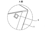
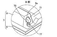
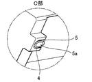
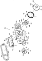
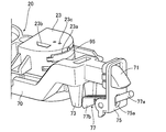
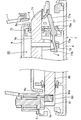
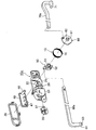
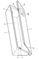
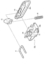
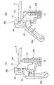
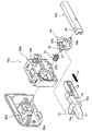
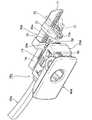
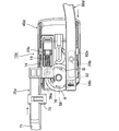
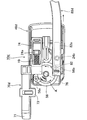
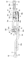
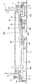
- FIG. 1 It is a disassembled perspective view which shows 1st Embodiment of the locking device of the opening-closing body which concerns on this invention. It is an expansion perspective view in the A section of FIG. It is an expansion perspective view in the B section of FIG. It is an expansion perspective view in the C section of FIG. It is an expansion perspective view in the D section of FIG. It is a perspective view which shows the contact locking means of the locking device. It is a disassembled perspective view of the principal part of the locking device. It is a back side perspective view of the important section of the locking device. It is a front side perspective view of the principal part of the locking device. It is a perspective view of the operation member which comprises the locking device. FIG.
- FIG. 3 is a front view of a main part in a state where an operation member is removed in the lock device. It is a principal part front view of the locking device.
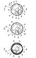
- FIG. 3 is a perspective view showing an operation member and a pair of rotors in the lock device. It is a principal part rear view of the locking device. It is principal part sectional drawing of the same locking device. In the same locking device, the operation of a pair of rotors is shown, (a) is an explanatory view of a state in which an operating member is operated, and (b) is a state in which a rod tip connected to one rotor is drawn and held. (C) is explanatory drawing of the state before operation of an operation member.
- FIG. 3 is a front view of a main part in a state where an operation member is removed in the lock device. It is a principal part front view of the locking device.
- FIG. 3 is a perspective view showing an operation member and a pair of rotors in the lock device. It is a
- FIG. 4 is a main part rear view in a state where a pair of rods is removed in the locking device.
- FIG. 3 is a perspective view showing a schematic structure of a holding unit that pulls and holds the rod tip in the lock device.
- (A) is explanatory drawing of the state before a rod front-end
- (b) is explanatory drawing of the state where the rod front-end
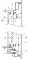
- the lock device it is a section explanatory view at the time of locking the opening of a fixed body in the state closed with an opening-and-closing body. In the same locking device, it is a section explanatory view in the state where the lock of the opening and closing body to the opening of the fixed body was released.
- FIG. 6 is an explanatory diagram of a state before the operation member is operated in the lock device.
- FIG. 6 is an explanatory diagram of a state before the operation member is operated in the lock device. It is explanatory drawing of the state by which the operation member was operated in the locking device. In the same locking device, after the operation member is operated, the rod tip portion is drawn and held by the holding means. It is a disassembled perspective view which shows 6th Embodiment of the locking device of the opening-closing body which concerns on this invention. It is a principal part expansion perspective view of the locking device.
- FIG. 6 is an explanatory diagram of a state before the operation member is operated in the lock device. It is explanatory drawing of the state by which the operation member was operated in the locking device.
- the lock device it is a section explanatory view at the time of locking the opening of a fixed body in the state closed with an opening-and-closing body. In the same locking device, it is a section explanatory view in the state where the lock of the opening and closing body to the opening of the fixed body was released. It is explanatory drawing which shows 7th Embodiment of the locking device of the opening / closing body which concerns on this invention. It is a section explanatory view of the locking device.
- a locking device 10 for an opening / closing body in this embodiment is a horizontally elongated glove box 1 provided on an instrument panel of a vehicle (“ It is used for opening and closing the lid 7 (“opening / closing body” in the present invention) attached to the opening 2 of the “fixing body”) so as to be opened and closed.
- a locking device for the opening and closing body for example, it can be applied to a structure in which a box-like glove box is rotatably attached to the opening of the instrument panel (in this case, the instrument panel is a “fixed body”,
- the glove box forms an “opening and closing body” or a structure in which the lid is attached to the opening of the instrument panel so that it can be opened and closed (in this case, the instrument panel is a “fixed body” and the lid is an “opening and closing body”)
- the instrument panel is a “fixed body” and the lid is an “opening and closing body”
- a square hole-shaped lock portion 3 is provided inside one side of the opening 2 of the glove box 1.
- This lock portion 3 is one of the constituent members of the mechanical engagement lock means in the present invention.
- the lock portion 3 may not have a hole shape but may have a shape with which a rod 70 described later can be engaged, such as a recess, a protrusion, a frame-like striker 6 (see FIG. 29), and the like. There is no.
- a recess 4 is provided inside the other side of the opening 2 of the glove box 1, and a magnet attracting member 5 is disposed in the recess 4.
- the magnet attracting member 5 is made of a metal (iron or the like) that can attract a magnet 83 (see FIG. 5) provided on a rod 80, which will be described later, and a tip end surface thereof forms a flat magnetic attracting surface 5a.
- the magnetic attraction surface 5a is arranged in the direction in which the lid 7 is opened (the direction in which the opening / closing body is opened from the opening of the fixed body).
- the magnet attracting member 5 constitutes one “member” constituting the contact locking means and the magnetic attracting means in the present invention.
- the magnet 83 may be attached to the recess 4 of the opening 2 of the glove box 1 and the magnet adsorbing member 5 may be attached to the rod 80, or the magnet 83 ( A magnet having a magnetic pole opposite to that shown in FIG.
- the lid 7 has a plate-like panel 8 that covers the opening 2 of the glove box 1, and a box-like box 9 disposed above the back side of the panel 8.
- the lower side of the lid 7 is attached to the opening 2 of the glove box 1 so as to be openable and closable via a support shaft (not shown).
- a locking device 10 is arranged in an internal space between the panel 8 and the box 9. Further, as shown in FIGS. 3 and 5, rod insertion holes 9 a and 9 a are formed from both sides of the box 9 in the width direction.
- the locking device 10 in this embodiment includes a housing 20 attached to the lid 7, a bezel 38 attached to the front side of the housing 20, and the housing 20.
- the operating member 40 that can be pushed in, the first rotor 50 and the second rotor 60 that are rotatably mounted on the housing 20, the rods 70 and 80 that are connected to the rotors 50 and 60, and the rod 70
- the engaging portion 71 (see FIG. 1) of the rod 80 is in a direction to engage the lock portion 3, and the contact portion 81 (see FIG. 1) of the rod 80 is in contact with the magnet attracting member 5.
- the torsion coil spring 15 that biases both the rods 70 and 80 is mainly constituted.
- the torsion coil spring 15 includes a winding part 16, an end part 17 bent from one circumferential end of the winding part 16 toward the winding part inner diameter side, and the winding part.
- the other end portion 18 is bent from the other circumferential end of the portion 16 toward the inner diameter side of the winding portion.
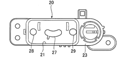
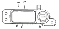
- the housing 20 has a horizontally long box shape, and a concave operation member arrangement portion 21 (FIG. 11) in which the operation member 40 is accommodated and arranged at the center of the front side.
- a cylindrical cylinder arrangement portion 23 in which the key cylinder 90 (see FIG. 9 and FIG. 15) is accommodated is formed on one side portion of the front side of the housing 20.
- a semicircular cylindrical wall 25 protrudes from the rear side of the housing 20 at a position aligned with the operation member disposing portion 21, and a pair of rotors 50, 60 are disposed on the inside thereof. (See FIG. 7).
- an arc-shaped cam insertion hole 27 is formed in the center of the bottom surface of the concave operation member arrangement portion 21 so as to communicate with the back side of the housing 20. Further, a round hole 28 is formed on the bottom surface of the operation member arrangement portion 21 on one side in the longitudinal direction, and a long hole 29 is formed on the other side in the longitudinal direction.
- Guide tubes 30 and 31 project from the periphery (see FIG. 8). As shown in FIGS. 14 and 15, groove portions 30a and 31a are formed on the outer circumferences of the guide cylinders 30 and 31, and locking protrusions 30b and 31b are formed on the inner sides of the groove portions 30a and 31a, respectively. ing.
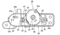
- a columnar rotating shaft 33 protrudes from a position adjacent to the cam insertion hole 27 on the back side of the housing 20.
- An arcuate guide wall 34 protrudes from the peripheral edge facing the rotation shaft 33, and serves as a guide when the pair of rotors 50 and 60 are rotated.
- retaining projections 35, 35 are provided on the inner periphery of the tip of the cylindrical wall 25 to prevent the second rotor 60 from coming off.
- a slot-like stopper insertion hole 23a is formed on the side of the cylinder placement portion 23 so as to communicate with the cylinder placement portion 23, and a stopper 95 (see FIG. 7) is provided. It is designed to be slidably inserted. Further, a retaining hole 23b and position restricting holes 23c and 23c are formed on the bottom surface of the cylinder placement portion 23.
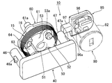
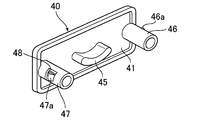
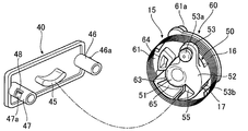
- the operating member 40 includes a horizontally long plate-like pressing portion 41 that fits into the concave operating member arrangement portion 21 of the housing 20, and a rear side center of the pressing 41. And a pressing convex portion 45 having a substantially arc-shaped cross section, and substantially cylindrical guide bosses 46 and 47 protruding from both longitudinal sides on the back side of the pressing portion 41. On the outer periphery of each guide boss 46, 47, retaining pieces 46 a, 47 a that can be bent toward the inside of the boss are formed via a U-shaped slit 48.
- the guide bosses 46 and 47 of the operation member 40 are respectively inserted into the guide cylinders 30 and 31 of the housing 20 to guide the pushing operation of the operation member 40.
- the retaining members 46a and 47a are slidably inserted into the groove portions 30a and 31a of the guide cylinders 30 and 31, and the retaining members 46a and 47a are engaged with the locking projections 30b and 31b, thereby operating members. 40 is prevented from coming off from the housing 20.
- the key cylinder 90 has a rotating body 92 that rotates by rotating a key (not shown), and a key protrusion 93 that protrudes from the back side of the rotating body 92.
- the stopper 95 has a plate-like base portion 96 and a projecting piece 97 protruding from one side portion of the base portion 96.
- the base 96 is formed with a movement hole 96a through which the key protrusion 93 moves, and the key protrusion 93 moves in the movement hole 96a so that the stopper 95 slides in the stopper insertion hole 23a. It has become.
- the base 96 is formed with a retaining claw 96b that engages with the retaining hole 23b of the housing 20 and a click claw 96c that removably engages with the position restricting holes 23c and 23c (see FIG. 7, FIG. 14 and FIG. 15).
- the key protrusion 93 of the key cylinder 90 is moved by the key rotation operation, and the stopper 95 slides, so that a part of the back side opening of the guide cylinder 31 of the housing 20 is covered by the protruding piece 97 of the stopper 95.
- the push-in of the operation member 40 is restricted and released.
- the first rotor 50 has a substantially cylindrical shape, and is connected to a cylindrical portion 51 through which the rotary shaft 33 is inserted and rotated, and an outer periphery of the cylindrical portion 51. And a receiving portion 52 having a substantially semicircular arc shape.
- An arm portion 53 is extended from one side in the circumferential direction of the receiving portion 52 toward the outer diameter direction, a connecting protrusion 53 a is protruded from the surface side of the arm portion 53, and a base end portion of the rod 70 is provided. Are connected.
- the surface side of the other side portion in the circumferential direction of the receiving portion 52 is formed so that the height gradually decreases toward the end portion along the circumferential direction.
- a cam slope 55 is formed.
- a spring hooking groove 53 b for hooking one end portion 17 of the torsion coil spring 15 is formed on the back side of the receiving portion 52 (opposite side of the cam inclined surface 55).
- the second rotor 60 protrudes in a cylindrical shape from a substantially disc-shaped base 61 and the periphery of the hole formed at the center of the base 61. And a cylindrical bearing portion 62 through which the rotating shaft 33 is inserted and rotatably supported.
- a receiving portion 63 is projected so as to be positioned on the circumferential extension line of the portion 52.
- the receiving portion 63 is also formed with a cam slope 65 formed so that its height gradually decreases toward the cam slope 55 side of the first rotor 50 along the circumferential direction. (See FIGS. 13, 15 and 16).
- a spring clamping portion 64 is projected from the front side of the base portion 61 at a position adjacent to the receiving portion 63 with a predetermined gap. Further, as shown in FIGS. 7 and 17, a connecting protrusion 61a is projected at a predetermined position on the back side of the base 61 so that the base end of the rod 80 is connected (see FIGS. 8 and 8). (See FIG. 14).
- the first rotor 50 is arranged on the front side of the second rotor 60, and the housing 20 rotates on the cylindrical portion 51 of the first rotor 50 and the bearing portion 62 of the second rotor 60.
- the shaft 33 By inserting the shaft 33, the first rotor 50 and the second rotor 60 are coaxially and rotatably mounted on the housing 20.
- the winding portion 16 of the torsion coil spring 15 is disposed on the outer periphery of the receiving portion 52 of the first rotor 50 and the receiving portion 63 of the second rotor 60, and the one end portion 17 is the spring pull of the first rotor 50.
- the other end 18 is hooked by the hooking groove 53 b and is sandwiched and attached by the spring clamping portion 64 of the second rotor 60.
- the cam inclined surface 55 of the first rotor 50 and the cam inclined surface 65 of the second rotor 60 are arranged so that the lowest ends thereof are opposed to each other (see FIG. 13), and The first rotor 50 and the second rotor 60 are rotated by the torsion coil spring 15 so that the lowest end portions of the cam inclined surfaces 55 and 65 are close to each other as shown by arrows in FIG. It has come to be.
- the 1st rotor 50 or the 2nd rotor 60 rotates independently of each other without being affected by the rotational operation of the other rotors.
- the pair of rods 70 and 80 has a rod shape extending linearly with a predetermined length.
- the rod 80 is formed longer than the rod 70.
- tip part of the rod 70 has comprised the engaging part 71 in which the outer surface made the taper shape, and becomes a part engaged / disengaged to the lock
- a frame-shaped rod holding portion 73 protrudes slightly from the distal end portion side of the rod 70.
- a flat magnetic adsorption surface 83a is provided in the direction in which the lid 7 is closed (opening / closing body with respect to the opening of the fixed body).
- a magnet 83 is embedded toward the closing direction), and this is a portion that contacts and joins the magnet attracting member 5 disposed in the glove box 1.
- the rod 70 and the rod 80 are respectively connected to the base end portions thereof, and are rotated and biased by the torsion coil spring 15 as indicated by arrows in FIG. 14, as shown by the arrow in FIG. 14, the contact portion 81 of the rod 80 is brought into contact with the magnet attracting member 5 so that the engagement portion 71 of the rod 70 is engaged with the lock portion 3. Both rods 70 and 80 are biased so as to be in the direction.
- the rod 70 is normally biased in the direction in which the engaging portion 71 engages with the lock portion 3 via the first rotor 60 that is rotationally biased by the torsion coil spring 15, as shown in FIG. 20.
- the engaging portion 71 is mechanically engaged with the lock portion 3.
- this rod 70 constitutes a “movable lock member” which is one of the constituent members of the mechanical engagement lock means in the present invention.
- rods 70, 70a, 70b are provided on one side of the lid 7.
- the engagement portion 71 is arranged, and the contact portion of the rods 80, 80a, 80b is arranged on the other side portion of the lid 7 to form a so-called side lock structure.
- a striker 6 (corresponding to the “lock portion” in the present invention) is provided at a predetermined position on the upper edge of the opening of the fixed body, and a movable lock member (hook 72) that engages and disengages with the striker 6 is provided.
- a lock structure may be provided in which the movable lock member is provided at a predetermined position in the upper part of the opening / closing body so as to be engaged with and disengaged from the striker 6.
- the term “mechanically engaged” means that the opening 2 of the glove box 1 is closed with the lid 7 and the lid 7 is opened in the direction of opening (the opening of the opening / closing body from the opening of the fixed body).
- the lock portion constituting the mechanical engagement lock means and the movable lock member are engaged with each other by the external force (in the case of the first to third embodiments, the engagement portion 71 is the lock portion).
- the hook 72 engages with the striker 6), and means that the hook 72 is not detached.
- the magnet 83 provided at the contact portion 81 is attracted to the magnet attracting member 5 disposed in the glove box 1 by a magnetic force, and the magnetic attracting surface 5 a of the magnet attracting member 5 and the magnet 83.
- the magnet attracting member 5 and the magnet 83 are joined by contacting the magnetic attracting surface 83a (see FIGS. 6 and 20), and in this state, the rod 80 is slid to apply an external force in the shearing direction. Can be peeled off (see FIG. 21).
- the magnet 83 constitutes the other “member” constituting the contact lock means and the magnetic attraction means in the present invention.
- contact and join means that a pair of members (magnet adsorbing member 5 and magnet 83) constituting the contact lock means in a state where the opening 2 of the glove box 1 is closed by the lid 7. Although they are in contact with each other, when an external force of a predetermined value or more is applied in the opening direction of the lid 7 or an external force is applied in the shearing direction by sliding the rod 80, the pair of members are peeled apart. Means that it can be configured.
- the magnet 83 of the contact portion 81 of the rod 80 slides in the direction away from the magnet attracting member 5 along the magnetic attracting surface 83a and the magnetic attracting surface 5a of the magnet attracting member 5, and the magnet 83 and the magnet
- the contact lock by magnetic attraction with the attracting member 5 is released (see FIG. 21). That is, when the operating member 40 is pushed in, the rods 70 and 80 are unlocked, and the lid 7 is opened from the opening 2 of the glove box 1.
- the operation member 40, the first rotor 50, and the second rotor 60 release the engagement by moving the movable lock member (rod 70) of the mechanical engagement lock means in the present invention.
- "Operating means" In this embodiment, the lock portion 3 constituting the mechanical engagement lock means and the engagement portion 71 of the rod 70 are mechanically engaged, and the magnet attracting member 5 and the magnet 83 constituting the contact lock means are brought into contact with each other.
- the mechanical engagement locking means and the contact locking means are not limited to the above structure.
- the contact lock means may be a hook-and-loop fastener or the like.
- the operating member 40 that constitutes the operating means, the first rotor 50 and the second rotor 60, and the rod 70 that constitutes the mechanical engagement locking means are open / close bodies.
- the magnet 83 of the contact portion 81 of the rod 80 that is disposed on one side of the lid 7 near the driver's seat and constitutes the contact lock means is on the other side of the lid 7 on the passenger seat side than the mechanical engagement lock means. It is arranged in the part.
- FIG. 1 shows the case where the vehicle is a right steering wheel.
- the locking device 10 of this embodiment has a holding means for holding the engaging portion 71 of the rod 70 in a retracted state so that the engaging portion 71 is not engaged with the locking portion 3.
- the holding means includes a frame-like holding frame 75 disposed inward of the rod insertion hole 9a (see FIG. 3) of the box 9 constituting the lid 7, and the holding frame. 75, and a lever 77 that is rotatably mounted to 75.
- a tip 77a of the lever 77 has a pin shape, is inserted through a long hole 75a formed in the holding frame 75, and can swing within the long hole 75a.
- the lever 77 is inserted and arranged in the frame-shaped rod holding portion 73 of the rod 70 in a state where the lever 77 is not pushed in.
- the base end 77b side is urged to rotate toward the panel 8 side of the lid 7 by an urging means (not shown) (see the arrow in FIG. 20).
- the opening 2 of the glove box 1 is locked in the closed state by the lid 7 by the mechanical engagement lock means and the contact lock means, and the engagement portion 71 of the rod 70 is attached in the direction in which the lock portion 3 is engaged.
- the first rotor 50 is rotated, and the engaging portion 71 of the rod 70 is slid in a direction not engaged with the lock portion 3, the biasing means (not shown)
- the lever 77 is rotated by the urging force, and its base end 77b is engaged with the lower end 73a of the rod holding portion 73 of the rod 70 (see FIGS. 18 and 21), and the engaging portion 71 of the rod 70 is the lock portion. 3 is held in a state where it is not engaged.
- the rod holding portion 73, the holding frame 75, and the lever 77 of the rod 70 constitute the “holding means” in the present invention.
- the cam slope 55 of the first rotor 50 is the lowest.
- the end portion and the lowest end portion of the cam slope 65 of the second rotor 60 are separated by a predetermined circumferential length.
- the locking device 10 includes a first rotor 50 so that the lowest end portions of the cam inclined surfaces 55 and 65 are brought close to each other by the torsion coil spring 15 before the opening 2 of the glove box 1 is closed.
- the second rotor 60 is urged to rotate (see FIG. 16C), and the rod 70 is engaged with the lock portion 3 in the direction of engaging the lock portion 3 via both rotors 50 and 60.
- Both rods 70 and 80 are biased in a direction in which the contact portion 81 of 80 is brought into contact with the magnet attracting member 5 (see FIGS. 14 and 20).
- the base end part 77b of the lever 77 is inserted into the rod holding part 73 of the rod 70 and the retracting holding of the rod 70 is released will be described (see FIGS. 19A and 20).
- the engaging portion 71 reaches the rectangular hole-shaped lock portion 3 of the opening 2, the first rotor 50 is rotationally biased by the torsion coil spring 15, and the rod 70 is pushed out toward the outside of the lid again.
- the engaging portion 71 is mechanically engaged with the lock portion 3, and the magnet 83 installed in the contact portion 81 of the rod 80 is magnetically applied to the magnet attracting member 5 disposed in the concave portion 4 of the glove box 1.
- the magnetic attracting surfaces 5a and 83a come into contact with each other, the magnet 83 and the magnet attracting member 5 are joined, and the opening 2 of the glove box 1 is locked in a closed state by the lid 7 (FIG. 20). reference).
- the magnetic attraction means that constitutes a pair of members constituting the abutting lock means includes the magnet attraction member 5 provided on the glove box 1 side and the magnet 83 provided on the abutting portion 81 of the rod 80. It is made up of. Therefore, when the lid 7 is closed with respect to the opening 2 of the glove box 1, as described above, the magnet 83 is attracted to the magnet attracting member 5 by the magnetic attraction force, and the lid is opened with respect to the opening 2 of the glove box 1. Since 7 is adsorbed, the lock portion 3 which is a mechanical engagement lock means and the engagement portion 71 of the rod 70 are easily engaged, and the lid 7 can be reliably locked.
- the operating member 40, the first rotor 50, and the second rotor 60 that constitute the operating means are disposed on one side of the lid 7 that is an opening / closing body, so that the driver can The operation member 40 can be easily operated.
- the rod 70 constituting the mechanical engagement locking means is also arranged on one side of the lid 7 near the driver's seat, when the driver closes the lid 7, the portion of the lid 7 near the driver's seat As a result, the engagement portion 71 of the rod 70 constituting the mechanical engagement lock means can be easily engaged with the lock portion 3, and the one-way engagement can be more easily suppressed.
- the operation member 40 is pushed into the housing 20. Then, the pushing convex portion 45 of the operating member 40 presses the cam slopes 55 and 65 of the rotors 50 and 60, respectively, and resists the rotational biasing force of the torsion coil spring 15, and the cam slopes of the rotors 50 and 60. Rotates so that the lowest ends of 55 and 65 are separated from each other (see FIG. 16A), and slides in a direction in which the engaging portion 71 of the rod 70 is not engaged with the lock portion 3 and is mechanically engaged.
- the magnet 83 of the contact portion 81 of the rod 80 slides in a direction away from the magnet attracting member 5 along the magnetic attracting surface 83a and the magnetic attracting surface 5a of the magnet attracting member 5.
- the magnet 83 and the magnet attracting member 5 are separated from each other, the contact lock by magnetic attraction is released (see FIG. 21), and the lid 7 can be opened from the opening 2 of the glove box 1 (see FIG. 1). .
- both the rod 70 and the rod 80 slide, and the engagement portion 71 of the rod 70 is removed from the lock portion 3. Since the engagement of the mechanical engagement locking means can be released, and the magnet 83 of the contact portion 81 of the rod 80 can also be removed from the magnet attracting member 5, and the joining of the contact lock means can also be released.
- the lid 7 can be smoothly opened from the opening 2 of the box 1.
- the abutment lock means is a magnetic attraction means comprising the magnet attraction member 5 and the magnet 83, and the magnet 83 provided at the abutment portion 81 of the rod 80 by pushing the operating member 40.
- it slides in a direction away from the magnet attracting member 5 along the magnetic attracting surface 83a and the magnetic attracting surface 5a of the magnet attracting member 5 (see FIG. 21). Therefore, the bonding between the magnet 83 and the magnet attracting member 5 by the magnetic attraction can be released with a relatively low operating force.
- the operation member 40 is pushed into the housing 20 with the opening 2 of the glove box 1 closed by the lid 7, and the engagement portion 71 of the rod 70 is engaged with the lock portion 3.
- the base end portion 77b of the lever 77 comes out of the rod holding portion 73 of the rod 70, engages with the lower end portion 73a of the rod holding portion 73, and The engaging portion 71 is held in a state where it is not engaged with the lock portion 3 (see FIGS. 19B and 21).
- the lid 7 is pushed in with respect to the opening part 2 of the glove box 1 again.
- the lid 7 can be closed smoothly with less pressing resistance because it does not contact the inner surface of the opening 2 of the glove box 1.
- the first rotor 50 or the second rotor 60 is configured to rotate independently of each other, and the rod 70 connected to the first rotor 50 is pulled and held by the holding means.
- the second rotor 60 is rotatable and the rod 80 connected thereto is slidable (see FIG. 16B), so that the lid 7 approaches the opening 2 of the glove box 1.
- the rod 80 is attracted to the magnet attracting member 5 by the magnetic attracting force of the magnet 83 and the magnet attracting member 5 constituting the contact locking means, and the lid 7 is closed so that the lid 7 is drawn.
- the distal end portion 77 a of the lever 77 is pressed to the periphery, and the lever 77 rotates, and the base end portion 77 b is inserted into the rod holding portion 73 to hold the engaging portion 71. State is canceled, the engaging portion 71 of the rod 70 is engaged with the locking portion 3 (see FIG. 20), it is possible to improve the operation feeling at the time of closing the lid 7.
- FIG. 22 to 24 show a second embodiment of the opening / closing body locking device according to the present invention. Note that substantially the same parts as those of the above-described embodiment are denoted by the same reference numerals, and description thereof is omitted.
- the locking device 10a (hereinafter referred to as “locking device 10a”) of the opening / closing body of this embodiment is provided on the upper surface side of the glove box 1 with the operating member 40, the first rotor 50, the second A housing 20 for housing the rotor 60 and the like is attached, and the rod 70a and the rod 80a are also disposed on the glove box 1 side.
- a hole-like lock portion (not shown) is formed on one side in the longitudinal direction of the box 9 of the lid 7, and a magnet attracting member 5 having a magnetic attracting surface 5 a is predetermined from the other longitudinal side of the box 9. It is extended in length.
- the rod 70a has a shape in which the tip end portion is bent in an L shape, and an engaging portion 71 is bent toward the inside of the glove box 1.
- the rod 80a has a shape in which the tip side is bent in an L-shape, and a magnet 83 is embedded in the contact portion 81 at the tip, and is inserted from a slide hole 4a formed on the other side of the glove box 1. Has been issued.
- the rods 70 a and 80 a are engaged with the locking portion 3 by engaging the engaging portion 71 of the rod 70 a via the first rotor 50 and the second rotor 60 that are rotationally biased by the torsion coil spring 15. So that the abutting portion 81 of the rod 80a is in the direction of abutting the magnet attracting member 5, that is, the engaging portion 71 of the rod 70a and the abutting portion 81 of the rod 80a are close to each other. The rods 70a and 80a are urged toward the inside of the box 1 (see the arrow in FIG. 24A).
- 25 to 28 show a third embodiment of a locking device for an opening / closing body according to the present invention. Note that substantially the same parts as those of the above-described embodiment are denoted by the same reference numerals, and description thereof is omitted.
- the embodiment is a form in which the operating member 40 is pushed into the housing 20, whereas the opening / closing body locking device 10 b (hereinafter referred to as “locking device 10 b”) of this embodiment. ) Has an operation member 40a attached so as to be able to rotate in a direction approaching and separating from the surface of the lid 7 which is an opening / closing body.
- the locking device 10b includes a housing 20a, cam members 85 and 85 having cam grooves 85a that are slidably held on both left and right sides of the housing 20a, and rods 70b and 80b connected to the cam members 85.
- the abutting portion 81 in which the magnet 83 (see FIG. 26) at the tip of the rod 80b is embedded in the direction in which the engaging portion 71 at the tip of the rod 70b is engaged with the lock portion 3 is disposed on the glove box 1 side.
- Coil springs 19 and 19 for urging the cam members 85 and 85, respectively, are provided in the direction in contact with the magnet attracting member 5.
- the operation member 40a has cylindrical portions 49, 49 formed on both left and right sides, and each cylindrical portion 49 is provided with a convex portion 49a that moves in the cam groove 85a of the cam member 85.
- the housing 20a is rotatably mounted.
- the operation member 40a is rotatable in a direction in which the lower end portion is gripped and pulled up.
- the operation member for example, the lower part thereof may be rotatably attached to the housing, the upper part may be gripped, and the operation member may be rotated in a downward direction. That is, “rotating the operation member in a direction away from the surface of the opening / closing body” in the present invention means not only the operation of pulling up the operation member but also a push-down operation.
- each convex portion 49a provided in the cylindrical portion 49 is disposed on the back side of the cam groove in a state where the tips of the rods 70b and 80b are urged outward of the lid (see FIG. 27). Then, by grasping and pulling up the lower end portion of the operation member 40a and rotating the operation member 40a in a direction away from the surface of the lid 7, a convex portion is formed along the inner periphery of the cam groove 85a as shown in FIG. 49a slides to retract the cam members 85, 85 and slide the engaging portion 71 of the rod 70b in a direction not engaged from the lock portion 3, and the magnet 83 of the contact portion 81 of the rod 80b It slides in the direction away from the magnet attracting member 5.
- the operating member 40 a is rotated in a direction away from the surface of the lid 7, thereby
- the engaging portion 71 of the rod 70b constituting the combined locking means moves in a direction not engaging with the locking portion 3, and the operating force by the operator when the operating member 40a is pulled up or pushed down acts on the lid 7. Therefore, the lid 7 can be opened more smoothly.
- 29 to 31 show a fourth embodiment of a locking device for an opening / closing body according to the present invention. Note that substantially the same parts as those of the above-described embodiment are denoted by the same reference numerals, and description thereof is omitted.
- locking device 10c The opening / closing body locking device 10c (hereinafter referred to as "locking device 10c") of this embodiment is installed on one side of the driver and is operated to be lifted up, as in the embodiment shown in FIGS.
- locking device 10c The opening / closing body locking device 10c (hereinafter referred to as "locking device 10c") of this embodiment is installed on one side of the driver and is operated to be lifted up, as in the embodiment shown in FIGS.
- the structure of the mechanical engagement locking means is different.
- a substantially U-shaped striker 6 (“locking portion in the present invention”) is formed on the upper edge of one side of the opening 2 of the glove box 1. And a hook 72 that engages with and disengages from the hook 72.
- the locking device 10c has a housing 20b attached to the lid 7.
- a cylindrical hook holding portion 22 is opened at the center in the longitudinal direction of the housing 20b. Is provided.
- a hook 72 (which forms the “movable lock member” in the present invention) is slidably disposed in a predetermined direction with the coil spring 19 interposed in the hook holding portion 22. Further, the hook 72 has a convex movement groove 72a formed on the front side of the lid. Further, the hook 72 is directed in a direction (here, upward) to be engaged with the striker 6 by the urging force of the coil spring 19. It is energized. Further, a striker receiving portion 26 having a frame shape is provided from the peripheral edge of the hook holding portion 22.
- the hook 72 of this embodiment is arranged so as to be vertically slidable with respect to the hook holding portion 22 of the housing 20b.
- the hook 72 is arranged with respect to the housing.
- the latch (which constitutes the “movable lock member” of the present invention) rotatably mounted may be urged to rotate in a direction not engaging with the striker provided in the opening of the fixed body by the urging means.
- the urging means There is no particular limitation.
- an operation member 40b is attached to the housing 20b so as to be capable of being pulled up, and a hook operation convex portion 45 is projected from the upper center on the back side of the operation member 40b.
- the hook operation convex portion 45 is normally disposed at a position aligned with the convex portion moving groove 72 a of the hook 72.
- the locking device 10c has a contact portion 84 that extends from the other side in the longitudinal direction of the box 9 of the lid 7 and has a magnet (not shown) embedded therein. 84 is in contact with and joined to the magnet attracting member 5 installed in the glove box 1.
- the contact portion 84 is independent of the housing 20b and the operation member 40b and has an independent structure. However, like the contact portion 81 of the rod 80 in the embodiment shown in FIGS. It is good also as a structure linked with an operation member.
- the slope of the hook 72 comes into contact with the striker 6, and the hook 72 slides downward against the urging force of the coil spring 19.
- the hook 72 is mechanically engaged with the striker 6 so that one side of the lid 7 closer to the driver is moved.
- the upper edge of the opening 2 of the glove box 1 are engaged with each other, and the abutting portion 84 is in contact with and joined to the magnet attracting member 5, and the opening 2 of the glove box 1 is locked in the closed state by the lid 7. Is done.
- the hook 72 and the striker 6 which are mechanical engagement lock means are mechanically engaged, and the contact portion 84 and the magnet attracting member 5 which are contact lock means are in contact with each other and joined.
- the hook 72 and the striker 6 constituting the mechanical engagement locking means are arranged on one side of the lid 7 near the driver, as in the above embodiment, so that the driver can When the lid 7 is closed, a portion closer to the driver of the lid 7 is pushed in, and the hook 72 can be easily engaged with the striker 6.
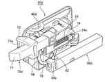
- the locking device 10d (hereinafter referred to as “locking device 10d”) of the opening / closing body of this embodiment has a housing 20d attached to the lid 7, and on the back side of the housing 20d.
- the rods 70d and 80d are slidably arranged via the rotor 56.
- Guide protrusions 24a and 24b are provided on the back side of the housing 20d so as to guide the sliding movement of the rods 70d and 80d.
- an operation member 40d is rotatably attached to the front side of the housing 20d so that the operation member 40d can be pulled up in the left-right direction of the vehicle.
- a rotor pressing convex portion 45a protrudes from the back side of one side portion in the width direction of the operation member 40d.
- the operating member 40d constitutes the “operating means” in the present invention.
- the locking device 10d has only one rotor 56, unlike the first and second embodiments having the two rotors 50 and 60.
- a shaft portion 57 projects from the center of the front side of the rotor 56, and the shaft portion 57 is inserted into a shaft hole (not shown) of the housing 20d so that the width on the back side of the housing 20d.
- a rotor 56 is rotatably mounted on one side portion in the direction.
- connection protrusions 56a and 56b for connecting to the rods 70d and 80d are provided to project at opposite positions on the periphery on the back side of the rotor 56. Further, the rotor 56 is rotationally biased by the torsion coil spring 15 in the direction of arrow A in FIG. 35 so as to bias a contact portion 81 (not shown) of the rod 80d in a direction to contact the magnet attracting member 5 (not shown). ing.
- the rod 56d is connected to the rotor 56 so as to move in conjunction with the rotation of the rotor 56. That is, a connecting portion 82 having a frame shape is provided at the base end portion of the rod 80d, and the connecting projection portion 56b of the rotor 56 is fitted to the connecting portion 82 so as not to be displaced in the connecting portion 82. is doing. Therefore, when the rotor 56 rotates in a predetermined direction (here, the rotational biasing direction of the rotor 56: the direction of arrow A) or the opposite direction (the direction of arrow B in FIG. 36), the rod 80d is slid in conjunction with it. It is configured.
- a guide recess 82a is formed on the base end side of the rod 80d (see FIG. 35), and the guide projection 24b enters the guide recess 82a to provide a slide guide for the rod 80d. Yes.
- a contact portion (not shown) on the distal end side of the rod 80d is provided with a magnet 83 (not shown) that forms the “other member” of the contact lock means and the magnetic attraction means of the present invention. 80d constitutes the “movable contact member” in the present invention.
- the rod 70d has a frame-like portion 74 at its proximal end (see FIGS. 32 and 33).
- the guide projection 24a of the housing 20d enters the frame-like portion 74, the coil spring 19 is accommodated in a compressed state (see FIGS. 34 and 35), and the engaging portion 71 at the tip of the rod 70d is located on the glove box side.
- the rod 70d is biased in a direction to engage with a lock portion 3 (not shown).
- the connecting projection 56a of the rotor 56 protrudes and protrudes in the middle of the rod 70d in the axial direction and is adjacent to the frame-shaped portion 74, and is engaged with the connecting projection 56a.
- An engagement / disengagement portion 76 that can be detached is provided.
- the engaging / disengaging portion 76 has a wall portion on the rod base end side opposite to the urging direction of the rotor 56, but the urging direction of the rotor 56.
- the rod tip side and the inner side surface side form an open frame shape.
- the rod 70d constitutes a “movable lock member” that constitutes the mechanical engagement lock means of the present invention.
- the locking device 10d has “holding means” including a rod holding portion 73, a holding frame 75, and a lever 77, as in the above embodiment.
- the lever 77 constituting the holding means engages with the lower end portion 73a of the rod holding portion 73 of the rod 70d, and the engaging portion 71 of the rod 70d engages with a lock portion (not shown). It is kept in a state that does not match.
- the lever 77 constituting the holding means is maintained in a state of being engaged with the lower end portion 73a of the rod holding portion 73 of the rod 70d and is held in a state of not being engaged with a lock portion (not shown) (see FIG. 37).
- the rod 70d constituting the movable locking member is engaged with the rotor 56 when the rotor 56 rotates in the direction opposite to the biasing direction, and the rotor 56 is When rotating in the urging direction, the engagement with the rotor 56 is released, and the holding means holds the rod 70d in a state not engaged with the lock portion 3 (not shown).
- the mechanism for engaging or disengaging the movable lock member with respect to can be realized by a relatively simple structure using one rotor 56, and when the lid 7 is opened (see FIG. 1), the movable lock member is engaged. The member can be held in a state in which the member is not engaged with the lock portion.
- the locking device 10e (hereinafter referred to as “locking device 10e”) of the opening / closing body of this embodiment is configured to be pulled up in the vehicle left-right direction, similarly to the locking device 10d of the fifth embodiment.
- a magnet 83 (which constitutes “the other member” of the contact lock means and the magnetic attraction means) is provided inside the other side of the opening 2 of the glove box 1.
- the magnet installation member 11 which has is installed. Furthermore, it is a position adjacent to the magnet 83 and is deeper in the opening 2 of the glove box 1 than the installation position of the magnet 83, that is, the front side in the direction in which the lid 7 is closed with respect to the opening 2 (in the present invention).
- a lock portion 3a is formed (see FIG. 42).
- a lock portion 3 is formed inside one side of the opening 2 of the glove box 1 as in the above-described embodiment.
- the first movable lock member here, the rod 70e
- the lock portion 3a is in the loosely fitted state of the second movable lock member (here, the rod 70f).
- the “second lock portion” in the present invention is engaged, and the “lock portion” in the present invention is constituted by the first lock portion and the second lock portion.
- the lock device 10 e has an intermediate rotor 66 attached to the lid 7.
- the intermediate rotor 66 is provided with connecting projections 66a and 66b projecting from both end portions in the circumferential direction via plate-like arm portions, and is rotatably mounted on the lid 7 via a rotor receiving member 67. Yes.
- the intermediate rotor 66 is urged to rotate in the direction of arrow A in FIG. 40 by the torsion coil spring 15a.
- the rod 70e is provided with the engagement / disengagement portion 76 that can be engaged and disengaged at the front end portion of the connection projection 56a of the rotor 56, and the guide protrusion on the rear side of the housing is provided in the axially intermediate portion.
- a frame-like portion 74 into which 24a is slidably inserted is provided.
- a connecting portion 78 having a frame shape is provided at the base end portion of the rod 70e, and the connecting protrusion 66a of the intermediate rotor 66 is connected in a fitted state.
- the rod 70e is biased in the direction in which the engaging portion 71 of the rod 70d is engaged with the lock portion 3 shown in FIG. 42 (see FIG. 40).
- the engaging portion 71 of the rod 70e is engaged with the lock portion 3 (see FIG. 42) forming the “first lock portion” on the glove box side.
- 70e constitutes the “first movable lock member” constituting the movable lock member in the present invention.
- the rod 80e constituting the movable abutting member has a shape in which the tip side is bent via a bent portion, and the magnet 83 of the magnet installation member 11 is provided at the tip of the bent portion.
- a magnet attracting member 5 (which forms “one member” of the contact lock means and the magnetic attracting means) made of a metal plate or the like is attached.
- a connecting portion 82 having a frame shape is provided on the proximal end side of the rod 80e, and the connecting projection 56b of the rotor 56 is connected in a fitted state.
- the rod 80d is biased in a direction in which the contact portion 81 of the rod 80d is in contact with the magnet 83 on the glove box side (see FIG. 40).
- the rod 70f has a shape bent in a substantially crank shape through a plurality of bent portions.
- the distal end portion 70m of the rod 70f is connected to the intermediate portion 70j and the base end portion of the rod 70f via a bent portion 70k bent obliquely outward with respect to the rod intermediate portion 70j. It is bent so as to be shifted in the axial direction.
- the engaging portion 71 of the rod 70f is located at a position ahead of the opening portion 2 of the glove box 1 in the direction of closing the lid 7 with respect to the opening portion 2 of the glove box 1 with respect to the rod 80e provided with the magnet attracting member 5. It is arranged adjacent to.
- a connecting portion 78 having a frame shape is provided at the base end portion of the rod 70f, and the connecting protrusion 66b of the intermediate rotor 66 is connected in a fitted state.
- the rod 70f is biased by the urging force in the direction in which the engaging portion 71 of the rod 70f is engaged with the lock portion 3a shown in FIG. 42 (see FIG. 40).
- the engaging portion 71 of the rod 70f is loosely engaged with the lock portion 3a forming the “second lock portion” inside the other side portion of the opening 2 of the glove box 1.
- the rod 70f constitutes a “second movable lock member” constituting the movable lock member according to the present invention, which is disposed at a position adjacent to the contact lock means.
- the engaging portion 71 of the rod 70f has a predetermined engagement with the engaged surface of the locking portion 3a (here, the inner peripheral surface of the rectangular hole-shaped locking portion 3a). It arrange
- “engaged in the loosely fitted state” means a state in which the engagement surface of the movable lock member is disposed to face the engagement surface of the lock portion with a gap, and the lock portion is In the case of the hole, it is preferable that the entire periphery of the portion inserted into the lock portion of the movable lock member has a gap so that it does not contact the inner periphery of the lock portion. Even in such a state, when an external force such as prying is applied to the lid 7, the engagement surface of the movable lock member is engaged with the engaged surface of the lock portion, and the lid 7 can be prevented from being opened.
- engagement between the movable lock member and the lock portion means that the movable lock member can be engaged with the lock portion when the movable lock member is inserted into the lock portion (described above).
- engagement means that the movable lock member can be engaged with the lock portion when the movable lock member is inserted into the lock portion (described above). The same applies to the first to fifth embodiments and the seventh embodiment described later).
- the engagement portion 71 of the rod 70e is not engaged with the lock portion 3.
- the rod 80e moves in a direction to release the joint with the other member (here, the magnet 83) of the contact lock means, and further, the intermediate rotor 66 rotates via the rod 70e.
- the rod 70f connected to the rotor 66 is configured to move in a direction not engaged with the lock portion 3.
- the rod 70f is interlocked with the rod 70e via the intermediate rotor 66.
- the intermediate rotor 66 is torsion coil spring 15a. Even if an attempt is made to rotate by this urging force, the rotation is restricted by the rod 70f. As a result, the rod 70f is also held in a state where it does not engage with the lock portion 3a.
- this locked state for example, a flathead screwdriver, a bar, or the like is inserted from the other side of the opening 2 of the glove box 1 where the contact lock means is disposed, and a pair of contact lock means is configured. Even if the members (the magnet 83 and the magnet adsorbing member 5) are forcibly peeled off, the engaging portion 71 of the rod 70f is engaged with the lock portion 3a in a loosely fitted state. Therefore, the lid 7 can be prevented from opening, and the lid 7 can be reliably maintained in the closed state.
- the engaging portion 71 of the rod 70e is mechanically engaged with the lock portion 3
- the engaging portion 71 of the rod 70f is loosely engaged with the lock portion 3a. Since it is engaged in the fitted state, it can be prevented that one side hook is generated as in the case where the engaging portions of the left and right rods of the side lock device are mechanically engaged on both sides of the glove box.
- the two locking means of the locking means and the contact locking means the locked state of the lid 7 can be stably maintained, and it is possible to suppress an adverse effect on the surface difference between the surface of the glove box 1 and the surface of the lid 7. it can.
- the second movable lock member constituting the movable lock member that is, the rod 70f
- the contact lock means the magnet 83 and the magnet attracting member 5
- 1 is arranged on the front side in the direction in which the lid 7 is closed (the front side in the closing direction of the opening and closing body) with respect to the opening 2 of the opening 1.
- the lock part 3a with which the engaging part 71 of the rod 70f is engaged in the loosely fitted state can be formed in the opening part 2 of the glove box 1, and the space of the opening part 2 can be secured.
- the locking device 10f of the opening / closing body has contact locking means provided at two locations on the opening of the fixed body or the opening / closing body.
- the mechanical engagement locking means is arranged at a position adjacent to at least one of them.
- the locking device 10f basically has a structure similar to that of the sixth embodiment, but the two rods 80e and 80g constituting the “movable contact member” of the present invention and the mechanical mechanism of the present invention.
- the sixth aspect of the present invention there is a structure having a total of four rods including two rods 70f and 70g which form a “movable lock member” of the combined lock means and are loosely engaged with the lock portion. It is different from the embodiment.
- magnet installation members 11 and 11 each having a magnet 83 are installed at two locations on both sides in the width direction of the opening 2 of the glove box 1.
- the rods 70f and 70g are engaged in a loosely-fitted state at positions adjacent to the magnets 83 and 83 and deeper in the opening 2 of the glove box 1 than the installation positions of the magnets 83.
- Portions 3a and 3a are formed (see FIG. 45).
- the two rods 80e and 80g constituting the “movable contact member” are slid in conjunction with the rotation of the rotor 56 with their base ends connected to the connecting projections 56a and 56b of the rotor 56.
- the rotor 56 is urged to rotate in the direction of arrow A in FIG. 44 by a torsion coil spring (not shown).
- the two rods 70 f and 70 g constituting the “movable lock member” have their base ends connected to the connecting protrusions 66 a and 66 b of the intermediate rotor 66, and slide in conjunction with the rotation of the intermediate rotor 66. Since the intermediate rotor 66 is urged in the direction of arrow A in FIG. 44 by a torsion coil spring (not shown), the intermediate rotor 66 is normally slid in a direction to engage with the lock portions 3a and 3a.
- a rod connecting pin 86 is provided in the middle of one of the rods 80g forming the “movable contact member”, and the rod connecting pin 86 is connected to the rod 70g forming the “movable lock member”. It is inserted into a frame-shaped recess 87 provided at a predetermined length along the longitudinal direction in the intermediate part.
- the rod connecting pin 86 rotates when the operating member 40d rotates the rotor 56 against the urging force of the torsion coil spring, and when the rods 80g and 80e slide in the direction away from the magnet 83, the base of the frame-like concave portion 87 of the rod 70g.
- the rod 70g is moved in a direction to be pulled out from the lock portion 3a by coming into contact with the end portion on the end side. Then, the other rod 70f also moves through the intermediate rotor 66 in the direction of being extracted from the lock portion 3a.
- the rotor 56 rotates in the direction of arrow A due to the biasing force of a torsion coil spring (not shown), and the rods 80g and 80e slide again in the direction in which they abut against the magnet 83.
- the rod connecting pin 86 moves through the frame-shaped recess 87, the rod 70g is maintained in a state of being disengaged by the lever without sliding in conjunction with the rotor 56.
- the rotation of the intermediate rotor 66 is also restricted via the rod 70g, so that the other rod 70f is also maintained in a disengaged state without sliding.
- the contact locking means is provided at two locations of the opening 2 of the glove box 1, so that the lid 7 is closed with respect to the opening 2 and the mechanical engagement locking means is movable.
- the rods 70f and 70g which are members, engage with the lock portions 3a and 3a, and each pair of members (the magnet 83 and the magnet adsorbing member 5 of the rods 80e and 80g) of the contact lock means provided at two locations are contacted. Since they are in contact with each other, it is possible to more reliably prevent one-side engagement by only the mechanical engagement locking means, and the locked state is stably held by the plurality of contact locking means, and the surface of the glove box 1 and the lid 7 can be stably held.
- the lid 7 approaches the opening 2 of the glove box 1.
- the lid 7 is closed so as to be smoothly pulled in by the magnetic attractive force of the pair of members of the two contact locking means, and the operation feeling when closing the lid 7 can be further improved.
- the first rotor 50, the second rotor 60, the rotor 56, and the intermediate rotor 66 are rotationally biased by using the torsion coil springs 15 and 15a, so that the rods 70, 70a, Although 70e, 70f, 70g, 80, 80a, 80d, 80e, etc. were slid, the rods may be urged to slide using, for example, a tension spring or a coil spring. It is not a thing. In that case, a tension spring, a coil spring or the like constitutes the “biasing means” in the present invention.
- the rods 70 and 70a in 1st, 2nd embodiment move indirectly via the 1st rotor 50 by operation of the operation member 40
- the rod 70b in 3rd Embodiment operates By the operation of the member 40a, it moves indirectly through the cam member 85, while the hook 72 in the fourth embodiment moves directly by the operation of the operation member 40b.
- the rods 70d and 80d in the fifth embodiment move indirectly through the rotor 56 by the operation of the operation member 40d
- 80e, and 80g are moved indirectly through the rotor 56 and the intermediate rotor 66 by the operation of the operation member 40d. That is, the movable lock member may be configured to move directly or indirectly by the operation member.
- the pair of left and right rods are slid through the pair of rotors 50, 60, the rotor 56, the intermediate rotor 66, etc., but the present invention is not limited to this.
- a pinion gear is adopted instead of the rotor, and a rack groove is formed in each of the pair of rods. The rack groove is engaged with the pinion gear, and one of the rods is slid, so that the pinion gear is interposed. The other rod may be slid.
Landscapes
- Engineering & Computer Science (AREA)
- Mechanical Engineering (AREA)
- Physics & Mathematics (AREA)
- Electromagnetism (AREA)
- Structural Engineering (AREA)
- Lock And Its Accessories (AREA)
- Vehicle Step Arrangements And Article Storage (AREA)
Abstract
L'invention porte sur un appareil de verrou pour un corps d'ouverture-fermeture, de telle sorte que la prise d'un seul élément de verrouillage est empêchée, de façon à permettre ainsi au corps d'ouverture-fermeture d'être maintenu de façon stable dans un état fermé sur une partie d'ouverture. Cet appareil de verrou (10) comporte : des moyens de verrouillage à prise mécanique, conçus de telle sorte qu'une tige (70) fixée à un couvercle (7) vient en prise avec une section de verrou (3) d'une boîte à gants (1) ou s'en sépare, la tige (70) étant normalement sollicitée vers la section de verrou (3) dans une direction de prise, et la tige (70) venant en prise avec la section de verrou (3) quand le couvercle (7) est fermé à l'aide de la force de sollicitation ; des moyens de verrouillage à contact, comprenant un élément de fixation d'aimant (5) disposé sur la boîte à gants (1) et un aimant (83) disposé sur le couvercle (7), conçus de telle sorte qu'un contact entre l'élément de fixation d'aimant (5) et un aimant (83) produira en résultat la formation d'une liaison entre ces derniers, et que l'application d'une force externe séparera l'élément de fixation d'aimant (5) et l'aimant (83) l'un de l'autre, et un élément d'actionnement pour déplacer la tige (70) des moyens de verrouillage à prise mécanique et relâcher la prise.
Priority Applications (1)
| Application Number | Priority Date | Filing Date | Title |
|---|---|---|---|
| JP2016504062A JP6204564B2 (ja) | 2014-02-20 | 2015-02-12 | 開閉体のロック装置 |
Applications Claiming Priority (2)
| Application Number | Priority Date | Filing Date | Title |
|---|---|---|---|
| JP2014-030601 | 2014-02-20 | ||
| JP2014030601 | 2014-02-20 |
Publications (1)
| Publication Number | Publication Date |
|---|---|
| WO2015125687A1 true WO2015125687A1 (fr) | 2015-08-27 |
Family
ID=53878192
Family Applications (1)
| Application Number | Title | Priority Date | Filing Date |
|---|---|---|---|
| PCT/JP2015/053829 Ceased WO2015125687A1 (fr) | 2014-02-20 | 2015-02-12 | Appareil de verrou pour corps d'ouverture-fermeture |
Country Status (2)
| Country | Link |
|---|---|
| JP (1) | JP6204564B2 (fr) |
| WO (1) | WO2015125687A1 (fr) |
Cited By (9)
| Publication number | Priority date | Publication date | Assignee | Title |
|---|---|---|---|---|
| FR3040341A1 (fr) * | 2015-08-28 | 2017-03-03 | Faurecia Interieur Ind | Ensemble de rangement pour vehicule |
| US20200270920A1 (en) * | 2019-02-27 | 2020-08-27 | Shanghai Yanfeng Jinqiao Automotive Trim Systems Co. Ltd. | Vehicle interior component |
| WO2021117594A1 (fr) * | 2019-12-10 | 2021-06-17 | 株式会社パイオラックス | Dispositif de déverrouillage |
| US11098503B2 (en) * | 2015-11-20 | 2021-08-24 | Piolax, Inc. | Lock device |
| CN113329410A (zh) * | 2021-03-09 | 2021-08-31 | 合肥学院 | 基于窄带自组网突发事件集群盲区覆盖系统 |
| US20210317690A1 (en) * | 2018-10-18 | 2021-10-14 | Piolax, Inc. | Lock device for opening/closing body |
| CN114336896A (zh) * | 2022-02-22 | 2022-04-12 | 深圳市六号数科科技有限公司 | 一种具有共享充电宝功能的共享电单车 |
| US20230010152A1 (en) * | 2019-12-10 | 2023-01-12 | Piolax, Inc. | Rotation member connecting structure and method for manufacturing said structure |
| US20240263490A1 (en) * | 2023-02-08 | 2024-08-08 | Nihon Plast Co., Ltd. | Lock apparatus and storage apparatus |
Citations (7)
| Publication number | Priority date | Publication date | Assignee | Title |
|---|---|---|---|---|
| JP2007100343A (ja) * | 2005-10-03 | 2007-04-19 | Piolax Inc | サイドロック装置 |
| JP2008173999A (ja) * | 2007-01-16 | 2008-07-31 | Calsonic Kansei Corp | 車両用収納装置 |
| JP2010053551A (ja) * | 2008-08-27 | 2010-03-11 | Tokai Rika Co Ltd | グローブボックスのロック装置 |
| JP2010077614A (ja) * | 2008-09-24 | 2010-04-08 | Tokai Rika Co Ltd | 開閉体の電気式施解錠装置 |
| JP2011247084A (ja) * | 2004-09-15 | 2011-12-08 | Piolax Inc | リッド開閉装置 |
| US20120256439A1 (en) * | 2009-12-18 | 2012-10-11 | Tofas Turk Otomobil Fabrikasi Anonim Sirketi | glove and storage box assembly |
| US20120261937A1 (en) * | 2011-04-18 | 2012-10-18 | Honda Motor Co., Ltd. | Push button mechanism for opening and closing a storage compartment for a vehicle |
-
2015
- 2015-02-12 JP JP2016504062A patent/JP6204564B2/ja active Active
- 2015-02-12 WO PCT/JP2015/053829 patent/WO2015125687A1/fr not_active Ceased
Patent Citations (7)
| Publication number | Priority date | Publication date | Assignee | Title |
|---|---|---|---|---|
| JP2011247084A (ja) * | 2004-09-15 | 2011-12-08 | Piolax Inc | リッド開閉装置 |
| JP2007100343A (ja) * | 2005-10-03 | 2007-04-19 | Piolax Inc | サイドロック装置 |
| JP2008173999A (ja) * | 2007-01-16 | 2008-07-31 | Calsonic Kansei Corp | 車両用収納装置 |
| JP2010053551A (ja) * | 2008-08-27 | 2010-03-11 | Tokai Rika Co Ltd | グローブボックスのロック装置 |
| JP2010077614A (ja) * | 2008-09-24 | 2010-04-08 | Tokai Rika Co Ltd | 開閉体の電気式施解錠装置 |
| US20120256439A1 (en) * | 2009-12-18 | 2012-10-11 | Tofas Turk Otomobil Fabrikasi Anonim Sirketi | glove and storage box assembly |
| US20120261937A1 (en) * | 2011-04-18 | 2012-10-18 | Honda Motor Co., Ltd. | Push button mechanism for opening and closing a storage compartment for a vehicle |
Cited By (17)
| Publication number | Priority date | Publication date | Assignee | Title |
|---|---|---|---|---|
| US10612278B2 (en) | 2015-08-28 | 2020-04-07 | Faurecia Interieur Industrie | Vehicle stowage assembly |
| FR3040341A1 (fr) * | 2015-08-28 | 2017-03-03 | Faurecia Interieur Ind | Ensemble de rangement pour vehicule |
| US11098503B2 (en) * | 2015-11-20 | 2021-08-24 | Piolax, Inc. | Lock device |
| US20210317690A1 (en) * | 2018-10-18 | 2021-10-14 | Piolax, Inc. | Lock device for opening/closing body |
| US11821244B2 (en) * | 2018-10-18 | 2023-11-21 | Piolax, Inc. | Lock device for opening/closing body |
| US20200270920A1 (en) * | 2019-02-27 | 2020-08-27 | Shanghai Yanfeng Jinqiao Automotive Trim Systems Co. Ltd. | Vehicle interior component |
| US11572723B2 (en) * | 2019-02-27 | 2023-02-07 | Shanghai Yanfeng Jinqiao Automotive Triim Systems Co. Ltd. | Vehicle interior component |
| JPWO2021117594A1 (fr) * | 2019-12-10 | 2021-06-17 | ||
| US20230010152A1 (en) * | 2019-12-10 | 2023-01-12 | Piolax, Inc. | Rotation member connecting structure and method for manufacturing said structure |
| JP7269372B2 (ja) | 2019-12-10 | 2023-05-08 | 株式会社パイオラックス | ロック解除装置 |
| WO2021117594A1 (fr) * | 2019-12-10 | 2021-06-17 | 株式会社パイオラックス | Dispositif de déverrouillage |
| US12203297B2 (en) | 2019-12-10 | 2025-01-21 | Piolax, Inc. | Unlocking device |
| US12371932B2 (en) * | 2019-12-10 | 2025-07-29 | Piolax, Inc. | Rotation member connecting structure and method for manufacturing said structure |
| CN113329410A (zh) * | 2021-03-09 | 2021-08-31 | 合肥学院 | 基于窄带自组网突发事件集群盲区覆盖系统 |
| CN114336896A (zh) * | 2022-02-22 | 2022-04-12 | 深圳市六号数科科技有限公司 | 一种具有共享充电宝功能的共享电单车 |
| US20240263490A1 (en) * | 2023-02-08 | 2024-08-08 | Nihon Plast Co., Ltd. | Lock apparatus and storage apparatus |
| US12559989B2 (en) * | 2023-02-08 | 2026-02-24 | Nihon Plast Co., Ltd. | Lock apparatus and storage apparatus |
Also Published As
| Publication number | Publication date |
|---|---|
| JP6204564B2 (ja) | 2017-09-27 |
| JPWO2015125687A1 (ja) | 2017-03-30 |
Similar Documents
| Publication | Publication Date | Title |
|---|---|---|
| JP6204564B2 (ja) | 開閉体のロック装置 | |
| JP5681832B2 (ja) | 開閉体のロック装置 | |
| JP6408147B2 (ja) | 開閉体の電動式ロック装置 | |
| KR100535763B1 (ko) | 글로브박스의 로드 작동장치 | |
| CN105003133B (zh) | 用于机动车辆的门的闩锁 | |
| JP6031523B2 (ja) | 開閉体のロック装置 | |
| JP6239277B2 (ja) | スライディングドア用アウトサイドハンドル | |
| WO2010038716A1 (fr) | Dispositif de verrouillage latéral | |
| JP5785271B2 (ja) | 開閉体のロック装置 | |
| JP2011012543A (ja) | リッド開閉装置 | |
| JP2018131817A (ja) | フードロック装置 | |
| WO2020080344A1 (fr) | Dispositif de verrouillage pour corps d'ouverture/fermeture | |
| JP5375588B2 (ja) | 車両用ドアロック装置 | |
| JP6418753B2 (ja) | 開閉体のロック装置 | |
| WO2017086426A1 (fr) | Dispositif de serrure | |
| JP2017002470A (ja) | 開閉体のロック装置 | |
| JP2010112122A (ja) | ドアラッチ装置 | |
| JP4518900B2 (ja) | リッド開閉装置 | |
| JP2010174567A (ja) | ドアラッチ装置 | |
| JP5249142B2 (ja) | パチンコ機のヒンジ装置 | |
| JP6317133B2 (ja) | 開閉体のロック装置及び押し込み式操作装置 | |
| JP2013036281A (ja) | 車両用収納装置 | |
| JPH11141207A (ja) | ラッチ錠 | |
| JP5948225B2 (ja) | 開閉体のロック装置 | |
| WO2015064387A1 (fr) | Dispositif d'ouverture/fermeture de porte de véhicule |
Legal Events
| Date | Code | Title | Description |
|---|---|---|---|
| 121 | Ep: the epo has been informed by wipo that ep was designated in this application |
Ref document number: 15751884 Country of ref document: EP Kind code of ref document: A1 |
|
| DPE1 | Request for preliminary examination filed after expiration of 19th month from priority date (pct application filed from 20040101) | ||
| ENP | Entry into the national phase |
Ref document number: 2016504062 Country of ref document: JP Kind code of ref document: A |
|
| NENP | Non-entry into the national phase |
Ref country code: DE |
|
| 122 | Ep: pct application non-entry in european phase |
Ref document number: 15751884 Country of ref document: EP Kind code of ref document: A1 |