WO2015125749A1 - ガス拡散電極基材ならびにそれを備える膜電極接合体および燃料電池 - Google Patents
ガス拡散電極基材ならびにそれを備える膜電極接合体および燃料電池 Download PDFInfo
- Publication number
- WO2015125749A1 WO2015125749A1 PCT/JP2015/054195 JP2015054195W WO2015125749A1 WO 2015125749 A1 WO2015125749 A1 WO 2015125749A1 JP 2015054195 W JP2015054195 W JP 2015054195W WO 2015125749 A1 WO2015125749 A1 WO 2015125749A1
- Authority
- WO
- WIPO (PCT)
- Prior art keywords
- electrode substrate
- gas diffusion
- void
- microporous
- diffusion electrode
- Prior art date
- Legal status (The legal status is an assumption and is not a legal conclusion. Google has not performed a legal analysis and makes no representation as to the accuracy of the status listed.)
- Ceased
Links
Classifications
-
- H—ELECTRICITY
- H01—ELECTRIC ELEMENTS
- H01M—PROCESSES OR MEANS, e.g. BATTERIES, FOR THE DIRECT CONVERSION OF CHEMICAL ENERGY INTO ELECTRICAL ENERGY
- H01M8/00—Fuel cells; Manufacture thereof
- H01M8/02—Details
- H01M8/0202—Collectors; Separators, e.g. bipolar separators; Interconnectors
- H01M8/023—Porous and characterised by the material
- H01M8/0241—Composites
- H01M8/0245—Composites in the form of layered or coated products
-
- H—ELECTRICITY
- H01—ELECTRIC ELEMENTS
- H01M—PROCESSES OR MEANS, e.g. BATTERIES, FOR THE DIRECT CONVERSION OF CHEMICAL ENERGY INTO ELECTRICAL ENERGY
- H01M8/00—Fuel cells; Manufacture thereof
- H01M8/02—Details
- H01M8/0202—Collectors; Separators, e.g. bipolar separators; Interconnectors
- H01M8/023—Porous and characterised by the material
- H01M8/0241—Composites
- H01M8/0243—Composites in the form of mixtures
-
- H—ELECTRICITY
- H01—ELECTRIC ELEMENTS
- H01M—PROCESSES OR MEANS, e.g. BATTERIES, FOR THE DIRECT CONVERSION OF CHEMICAL ENERGY INTO ELECTRICAL ENERGY
- H01M8/00—Fuel cells; Manufacture thereof
- H01M8/02—Details
- H01M8/0202—Collectors; Separators, e.g. bipolar separators; Interconnectors
- H01M8/023—Porous and characterised by the material
- H01M8/0234—Carbonaceous material
-
- H—ELECTRICITY
- H01—ELECTRIC ELEMENTS
- H01M—PROCESSES OR MEANS, e.g. BATTERIES, FOR THE DIRECT CONVERSION OF CHEMICAL ENERGY INTO ELECTRICAL ENERGY
- H01M8/00—Fuel cells; Manufacture thereof
- H01M8/02—Details
- H01M8/0202—Collectors; Separators, e.g. bipolar separators; Interconnectors
- H01M8/023—Porous and characterised by the material
- H01M8/0239—Organic resins; Organic polymers
-
- H—ELECTRICITY
- H01—ELECTRIC ELEMENTS
- H01M—PROCESSES OR MEANS, e.g. BATTERIES, FOR THE DIRECT CONVERSION OF CHEMICAL ENERGY INTO ELECTRICAL ENERGY
- H01M8/00—Fuel cells; Manufacture thereof
- H01M8/10—Fuel cells with solid electrolytes
- H01M8/1004—Fuel cells with solid electrolytes characterised by membrane-electrode assemblies [MEA]
-
- H—ELECTRICITY
- H01—ELECTRIC ELEMENTS
- H01M—PROCESSES OR MEANS, e.g. BATTERIES, FOR THE DIRECT CONVERSION OF CHEMICAL ENERGY INTO ELECTRICAL ENERGY
- H01M8/00—Fuel cells; Manufacture thereof
- H01M8/10—Fuel cells with solid electrolytes
- H01M2008/1095—Fuel cells with polymeric electrolytes
-
- Y—GENERAL TAGGING OF NEW TECHNOLOGICAL DEVELOPMENTS; GENERAL TAGGING OF CROSS-SECTIONAL TECHNOLOGIES SPANNING OVER SEVERAL SECTIONS OF THE IPC; TECHNICAL SUBJECTS COVERED BY FORMER USPC CROSS-REFERENCE ART COLLECTIONS [XRACs] AND DIGESTS
- Y02—TECHNOLOGIES OR APPLICATIONS FOR MITIGATION OR ADAPTATION AGAINST CLIMATE CHANGE
- Y02E—REDUCTION OF GREENHOUSE GAS [GHG] EMISSIONS, RELATED TO ENERGY GENERATION, TRANSMISSION OR DISTRIBUTION
- Y02E60/00—Enabling technologies; Technologies with a potential or indirect contribution to GHG emissions mitigation
- Y02E60/30—Hydrogen technology
- Y02E60/50—Fuel cells
Definitions
- the present invention relates to a gas diffusion electrode base material suitably used for a fuel cell, particularly a polymer electrolyte fuel cell. More specifically, it has good dryness at high temperatures and good gas diffusibility and drainage even under low temperature and high humidification conditions, so it maintains low mechanical properties, electrical conductivity, and thermal conductivity.
- the present invention relates to a gas diffusion electrode substrate that can exhibit high power generation performance over a wide temperature range from high to low.
- a polymer electrolyte fuel cell that supplies a fuel gas containing hydrogen to the anode and an oxidizing gas containing oxygen to the cathode to obtain an electromotive force by an electrochemical reaction occurring at both electrodes is generally a separator, gas diffusion An electrode base material, a catalyst layer, an electrolyte membrane, a catalyst layer, a gas diffusion electrode base material, and a separator are laminated in order.
- the gas diffusion electrode base material has high gas diffusibility for diffusing the gas supplied from the separator to the catalyst layer, and high drainage for discharging liquid water generated by the electrochemical reaction to the separator. High conductivity is required to extract current, and gas diffusion electrode substrates made of carbon fiber or the like are widely used.
- Patent Document 1 a stable power generation performance can be obtained under low and high humidification conditions by impregnating an electrode base material with a carbon porous body, that is, a microporous portion, so that the density of the impregnation layer is within a certain range. It is disclosed. However, the structure obtained by such a method in which the microporous portion is impregnated in the electrode base material cannot satisfy both high gas diffusibility and high drainage at the same time, and in particular, power generation performance at low temperatures is insufficient. there were.
- Patent Document 2 through holes are formed by putting a large amount of pore-forming particles inside the microporous layer, and water and gas passages are separated, so that high performance can be achieved in both dry and humid conditions.
- a technique for obtaining the above is disclosed.
- the method disclosed in Patent Document 2 has a problem in that moisture discharged from the microporous layer accumulates in the carbon paper and hinders gas diffusion, and sufficient performance cannot be obtained.
- the object of the present invention is to have high flooding resistance due to excellent gas diffusibility and drainage even under low temperature and high humidification conditions while having dry-up resistance at high temperature, and has high mechanical properties, electrical conductivity, thermal conductivity It is an object to provide a gas diffusion electrode substrate capable of exhibiting high power generation performance over a wide temperature range from low temperature to high temperature without greatly impairing the above.
- the gas diffusion electrode substrate of the present invention employs the following means in order to solve such problems. That is, a gas diffusion electrode substrate composed of an electrode substrate and a microporous portion used in a fuel cell, wherein the microporous portion (A) has a thickness of 10 ⁇ m or more and 60 ⁇ m or less on one side of the electrode substrate.
- the void volume of the void having a void diameter of 0.1 ⁇ m or more and less than 10 ⁇ m is 0.9 to 5 times the void volume of the void having a void diameter of 10 ⁇ m or more and less than 100 ⁇ m. It is a gas diffusion electrode substrate within the following range.
- the membrane electrode assembly of the present invention employs the following means in order to solve such problems. That is, the membrane electrode assembly has a catalyst layer on both sides of the electrolyte membrane, and further has the gas diffusion electrode substrate described above outside the catalyst layer.
- the fuel cell of the present invention employs the following means in order to solve such a problem. That is, the fuel cell has separators on both sides of the membrane electrode assembly described above.
- the gas diffusion electrode substrate by promoting the discharge of liquid water at the gas diffusion electrode substrate, the gas diffusion electrode substrate has high flooding resistance due to excellent gas diffusibility and drainage even under low temperature and high humidification conditions. A material can be obtained. For this reason, when the gas diffusion electrode substrate of the present invention is used in a fuel cell, high power generation performance can be expressed over a wide temperature range from low temperature to high temperature.
- the gas diffusion electrode substrate of the present invention also has good mechanical strength, electrical conductivity, and thermal conductivity.
- the voids distributed between the pore diameters of 10 ⁇ m or more and less than 100 ⁇ m provide a large gas diffusion effect and serve as liquid water passages, but when a large amount of liquid water is generated, the liquid water stays in the voids. This is an obstacle to gas diffusion.
- the void diameter is distributed between 0.1 ⁇ m and less than 10 ⁇ m, the gas diffusion effect is not large, but a large amount of liquid water is generated by suppressing the retention of liquid water inside it.
- the gas diffusion electrode substrate of the present invention is composed of an electrode substrate and a microporous portion, and it is necessary that the microporous portion (A) is formed on one surface of the electrode substrate.
- the microporous portion (A) is a microporous portion that is layered on the surface of the electrode substrate, and is a microporous portion that is impregnated in at least part of the voids of the electrode substrate, which will be described later. It is distinguished from (B).
- a substrate made of only carbon paper or the like and not provided with a microporous portion, or a portion of the “gas diffusion electrode substrate” is referred to as an “electrode substrate”, and the microporous portion is provided on the electrode substrate.
- the provided base material is referred to as “gas diffusion electrode base material”.
- the electrode base material in the present invention has high gas diffusibility for diffusing the gas supplied from the separator to the catalyst layer, high drainage for discharging liquid water generated by the electrochemical reaction to the separator, and generation High electrical conductivity is needed to extract the measured current.
- a conductive porous body specifically, a porous body containing carbon fibers such as carbon fiber woven fabric, carbon fiber nonwoven fabric, carbon fiber papermaking body, foam sintered metal, metal mesh, expanded
- a metal porous body such as metal is used, and among them, it is preferable to use a porous body containing carbon fiber because of its excellent corrosion resistance.
- the carbon fiber woven fabric may be a woven fabric obtained by weaving carbon fibers, or may be obtained by firing a woven fabric obtained by weaving carbon fiber precursor fibers.
- a carbon fiber nonwoven fabric it is obtained by firing after applying processing such as compression to a nonwoven fabric processed from carbon fiber precursor fiber, even those processed into a nonwoven fabric carbon fiber, A so-called felt type may be used.
- a base material obtained by binding a carbon fiber papermaking body with carbide that is, “carbon paper”.
- a substrate formed by binding a carbon fiber papermaking body with a carbide is usually obtained by impregnating a carbon fiber papermaking body with a resin and carbonizing it, as will be described later.
- Examples of the carbon fiber include polyacrylonitrile (PAN), pitch, and rayon carbon fibers.
- PAN polyacrylonitrile
- pitch rayon carbon fibers.
- PAN-based and pitch-based carbon fibers are preferably used in the present invention because of excellent mechanical strength.
- the thickness of the electrode substrate is preferably 50 ⁇ m or more and 190 ⁇ m or less.
- the thickness of the electrode base material is more preferably 60 ⁇ m or more, and more preferably 160 ⁇ m or less. This is because the microporous portion (B) can be impregnated to the inside of the electrode substrate by making the electrode substrate have a thickness of 190 ⁇ m or less, and the void distribution characteristic of the present invention can be obtained.
- the electrode substrate is 50 ⁇ m or thicker, gas diffusion in the in-plane direction can be increased under the ribs of the separator and gas diffusion to the catalyst layer under the ribs can be sufficiently achieved. It contributes to the improvement.
- the thickness of the electrode substrate can be measured using a micrometer in a state where the electrode substrate is pressurized at a surface pressure of 0.15 MPa.
- the thickness is measured at 10 locations at random, and the average value is calculated as the thickness of the electrode substrate.
- the thickness of the electrode substrate may be measured using an electrode substrate separated from the gas diffusion electrode substrate. For example, after heating the gas diffusion electrode substrate in the atmosphere at 600 ° C. for 30 minutes to oxidatively decompose the resin composition contained in the microporous portion in the gas diffusion electrode substrate, ultrasonic waves are used in a solvent such as ethanol. By performing the treatment, the residue of the microporous portion can be removed and the electrode substrate can be taken out, and the thickness can be measured in the same manner as described above using such an electrode substrate. Further, the thickness of the base material from which the microporous portion (A) existing on the surface thereof is peeled from the gas diffusion electrode base material may be the thickness of the electrode base material.
- the base material from which the microporous portion (A) existing on the surface thereof has been peeled off from the gas diffusion electrode base material may be referred to as an electrode base material portion.
- an adhesive tape such as “Scotch” (registered trademark) tape # 810 (manufactured by 3M) is adhered to the microporous portion (A) side of the surface of the gas diffusion electrode substrate with a surface pressure of 0.15 MPa and peeled off. This adhesion and peeling are repeated, and it can be said that the microporous part (A) can be peeled off when the mass reduction by peeling with the pressure-sensitive adhesive tape becomes 1% by mass or less, and an electrode substrate part can be obtained.
- the thickness measured by the above-described method for this electrode substrate portion can be the thickness of the electrode substrate.
- the bulk density of the electrode substrate is preferably 0.2 g / cm 3 or more, more preferably 0.22 g / cm 3 or more, and further preferably 0.24 g / cm 3 or more. preferable.
- the bulk density of the electrode substrate is preferably 0.4 g / cm 3 or less, more preferably 0.35 g / cm 3 or less, and further preferably 0.3 g / cm 3 or less.
- the bulk density is 0.2 g / cm 3 or more, the water vapor diffusibility is small, dry-up can be further suppressed, the mechanical properties of the electrode substrate are improved, and the electrolyte membrane and the catalyst layer are sufficient. Can support you.
- the conductivity is high, and the power generation performance is improved at both high and low temperatures.
- the bulk density is 0.4 g / cm 3 or less, drainage is improved and flooding can be further suppressed.
- the bulk density of the electrode base material was cut out using a 2 cm square electrode base material as a test piece, the mass of the test piece was measured, and the mass was determined based on the thickness of the electrode base material obtained by the above-described method and the cut-out area of the test piece ( It can be determined by dividing by the volume that is the product of 4 cm 2 ). Five specimens are measured, and the average is taken as the bulk density.
- the electrode substrate used in the present invention has a large surface roughness on the opposite side to the surface roughness on which the microporous portion (A) is formed with a difference of 1 ⁇ m to 5 ⁇ m. preferable. If there is a certain difference in surface roughness between the front and back surfaces of the electrode substrate, when the microporous portion (B) is impregnated, flow occurs in the direction perpendicular to the surface of the electrode substrate, and the microporous portion (B) is straight. It becomes easy to form a continuous structure in the direction. For this reason, drainage from the microporous portion (B) having a void distribution obtained in the present invention to the void formed by the electrode base material can be promoted.
- the microporous portion (B) by not increasing the difference in surface roughness too much, it is possible to suppress the microporous portion (B) from being biased in the direction perpendicular to the surface, and the amount of adhesion on the surface of one of the electrode base materials can be suppressed.
- a continuous structure can be formed.
- Such a difference in surface roughness is preferably 2 ⁇ m or more, and more preferably 4.5 ⁇ m or less.
- the surface roughness of the electrode substrate is measured by measuring a 5 mm square range on the surface of the electrode substrate using a laser microscope or the like, and after correcting the surface inclination, the arithmetic average roughness Ra [ ⁇ m of the surface] ] Can be obtained.
- the gas diffusion electrode base material needs to have a microporous portion (A) formed on one side of the electrode base material.
- the microporous part (A) has high gas diffusibility for diffusing the gas supplied from the separator to the catalyst layer, and high drainage for discharging liquid water generated by the electrochemical reaction to the separator. High electrical conductivity is needed to extract the measured current. Furthermore, it has a function of promoting the reverse diffusion of moisture into the electrolyte membrane and moistening the electrolyte membrane.
- the thickness of the microporous portion (A) is preferably 10 ⁇ m or more, and more preferably 15 ⁇ m or more.
- the thickness of the microporous portion (A) is preferably 60 ⁇ m or less, and more preferably 40 ⁇ m or less.
- the electrode base material surface can be covered so as to isolate the electrode base material from the catalyst layer, and the electrode base material is prevented from penetrating into the catalyst layer.
- the durability of the electrolyte membrane can be improved, but also the reverse diffusion of water vapor generated at the cathode to the anode is promoted, and the dry-up can be further suppressed.
- the thermal conductivity can be increased, so that diffusion of heat can not only suppress the dry-up of the electrolyte membrane, but also improve drainage. Flooding can be suppressed.
- the thickness of the microporous part (A) can be obtained by subtracting the thickness of the electrode base material from the thickness of the gas diffusion electrode base material.
- the thickness of the gas diffusion electrode substrate can be determined using a micrometer in a state in which the gas diffusion electrode substrate is pressurized at a surface pressure of 0.15 MPa, similarly to the thickness of the electrode substrate.
- the thickness is measured at 10 locations at random, and the average value is calculated as the thickness of the gas diffusion electrode substrate.
- the basis weight of the microporous part (A) is preferably 5 g / m 2 or more, more preferably 10 g / m 2 or more, and further preferably 16 g / m 2 or more.
- the basis weight of the microporous part (A) is preferably 35 g / m 2 or less, more preferably 30 g / m 2 or less, further preferably 25 g / m 2 or less, and 20 g / m 2. More preferably, it is as follows.
- the basis weight means the mass per unit area.
- the basis weight of the microporous part (A) is 5 g / m 2 or more, the electrode substrate surface can be covered, the durability of the electrolyte membrane can be improved, and the reverse diffusion of water vapor generated at the cathode to the anode is promoted. And dry-up can be suppressed. Further, when the basis weight of the microporous portion (A) is 35 g / m 2 or less, the drainage performance is further improved, and flooding can be further suppressed.
- the basis weight of the microporous portion (A) can be obtained by subtracting the basis weight of the electrode base material portion from the basis weight of the gas diffusion electrode base material.
- the basis weight of the gas diffusion electrode base material and the basis weight of the electrode base material part are determined by cutting out a 10 cm square base material as a test piece and dividing the mass of the test piece by the area of the test piece (0.01 m 2 ). Can do.
- an electrode base material part can be taken out from a gas diffusion electrode base material by the method by peeling mentioned above regarding the measurement of the thickness of an electrode base material.
- the basis weight of the microporous part (A) may be obtained by subtracting the basis weight of the microporous part (B) from the basis weight of the entire microporous part.
- the basis weight of the entire microporous portion may be obtained by subtracting the basis weight of the electrode base material from the basis weight of the gas diffusion electrode base material.
- the basis weight of the microporous part (B) is obtained by subtracting the basis weight of the electrode base material from the basis weight of the electrode base material impregnated with the microporous part (B) before applying the carbon coating liquid of the microporous part (A).
- the gas diffusion electrode base material usually has a structure in which the microporous portion (B) is impregnated inside at least a part of the electrode base material.
- the microporous part (B) is a microporous part impregnated in the electrode base material.
- being impregnated means that at least a part of the void formed by the electrode substrate itself is filled with the microporous portion (B).
- the microporous portion is usually a porous body having a void diameter of less than 10 ⁇ m.
- the surface of the electrode substrate part is made by a cutting method such as ion milling or microtome, and the cross section is observed with an optical microscope or a scanning electron microscope.
- the voids are impregnated if the microporous part, which is a porous body, is partially filled.
- the gap is impregnated if the void filling rate described later is 10% or more.
- voids distributed between 10 ⁇ m and less than 100 ⁇ m are present in the electrode substrate. While providing a large gas diffusion effect and serving as a passage for liquid water, under the power generation conditions in a high current region where a large amount of liquid water is generated, the liquid water stays in the gap, which becomes an obstruction factor for gas diffusion.
- the void diameter is distributed between 0.1 ⁇ m and less than 10 ⁇ m, the gas diffusion effect is not large, but it has the effect of suppressing the retention of liquid water therein, so that a large amount of liquid water is generated. Gas can be diffused even under low temperature and high humidity conditions.
- the voids formed by the electrode substrate itself that is, the voids inherently possessed by the electrode substrate, are distributed within a void diameter of 10 ⁇ m or more and less than 100 ⁇ m, and the void volume in this range is V (10-100) .
- voids formed by the microporous portion are distributed between void diameters of 0.1 ⁇ m or more and less than 10 ⁇ m, and the void volume in this range is V (0.1-10) .
- a void having a void diameter of 10 ⁇ m or more and less than 100 ⁇ m gives a large gas diffusion effect and becomes a passage for liquid water.
- a void having a void diameter of 0.1 ⁇ m or more and less than 10 ⁇ m has an effect of suppressing the retention of liquid water inside the void, although the gas diffusion effect is not as great as that of a void having a void diameter of 10 ⁇ m or more and less than 100 ⁇ m. Therefore, even when a large amount of liquid water is generated, the gas can be diffused through a gap of 0.1 ⁇ m or more and less than 10 ⁇ m.
- the inventors of the present invention which has been discovered by diligently investigating the movement of water in the gas diffusion electrode substrate, have the void volume in these two ranges in order to efficiently diffuse the fuel gas and discharge the water. It was found that the ratio is important and there is an optimum ratio for this control width.
- the specific ratio is that V (0.1-10) is in the range of 0.9 to 5 times with respect to V (10-100) .
- the ratio of V (0.1-10) to V (10-100) is preferably 1 or more, and more preferably 1.1 or more.
- the ratio of V (0.1-10) to V (10-100) is preferably 3 times or less, more preferably 2 times or less. If such a ratio is 0.9 times or more, the microporous part can be impregnated into the voids inherent in the electrode base material to suppress the retention of water in the liquid state. Even under conditions, gas diffusibility is good and power generation performance can be improved.
- the gas diffusibility is good, and water discharged from the small voids through the large voids even under low temperature and high humidification conditions. It can be discharged to the separator side.
- the ratio of V (0.1-10) to V (10-100) increases to 8 or more, and the voids inside the electrode substrate are excessive in the microporous portion. And the drainage of liquid water is reduced, so that the flooding resistance is lowered. This is because voids having a void diameter of 10 ⁇ m or more and less than 100 ⁇ m are blocked, resulting in a decrease in gas diffusion.
- V (0.1-10) and V (10-100) are effective to impregnate the electrode substrate with the microporous portion (B).
- V (0.1-10) can be increased as the number of microporous parts impregnated at this time increases.
- the basis weight of the microporous part (B) is 15% of the basis weight of the electrode base material. It can obtain by setting it as 75% or less of range.
- the electrode substrate has a structure in which the microporous portion (B) is impregnated
- gas diffusion is better while the microporous portion (B) has a smaller gap than the gap originally formed by the electrode substrate.
- the microporous portion (B) has a reasonably large void. This is because the water-repellent porous body has a size of around 1 ⁇ m, specifically, a void diameter in the range of 0.3 to 3 ⁇ m, so that the voids formed inside the microporous part (B) are connected to each other. This is because gas can be provided with good gas diffusibility.
- the void volume V (0.03-0.3) corresponding to a void diameter of 0.03 ⁇ m or more and less than 0.3 ⁇ m, which is a relatively small void is relatively large.
- the gas is excellent in gas diffusibility inside the microporous part (B), It is possible to form a microporous portion with good drainage of the liquid condensed in step (b).
- the structure of the electrode base material part excellent in gas diffusibility and drainage can be formed, and higher drainage and gas diffusivity can be made compatible in the whole gas diffusion electrode.
- a void volume V (0.03-0.3) corresponding to a void diameter of 0.03 ⁇ m or more and less than 0.3 ⁇ m is a relatively large void volume corresponding to a void diameter of 0.3 ⁇ m or more and less than 3 ⁇ m.
- V (0.3-3) is preferable.
- the electrode base material impregnated with the microporous part (B) corresponds to the electrode base part described above.
- the ratio of V (0.03-0.3) to V (0.3-3) is more preferably 0.9 times or less in the gas diffusion electrode substrate and / or electrode substrate portion. More preferably, it is 0.8 times or less.
- mercury is pressure-injected into the void to grasp the penetration.
- a test piece was cut out from the measurement target substrate, and a void diameter / void was measured using a porosimeter V (10-100) and V (0.1-10) in the measurement target substrate can be obtained by measuring the volume and obtaining the cumulative difference between the void diameter and the void volume. Further, V (0.03-0.3) and V (0.3-3) in the measurement target base material can be obtained by comparing the void volume of the portion having a void diameter of 0.03 ⁇ m or more and less than 3 ⁇ m. it can.
- a porosimeter Shimadzu Corporation autopore IV 9500 or its equivalent can be used as a porosimeter.
- the measurement target substrate may be a gas diffusion electrode substrate taken out from the stack of fuel cells.
- the gas diffusion electrode base material may be taken out by separating with (3).
- the electrode base material (electrode base material part) impregnated with the microporous part (B) can be taken out from the gas diffusion electrode base material by the method described above with respect to the measurement of the thickness of the electrode base material.
- composition of microporous part From the viewpoint of improving electrical conductivity and drainage, it is preferable to use a porous body containing a carbon-based filler and a water repellent for the microporous portion.
- Carbon black is a typical carbon-based filler.
- the microporous part (A) laminated on the surface of the electrode base material and the microporous part (B) impregnated in the electrode base material may have the same composition, Different compositions may be used.
- the microporous portion (B) In order to form a void volume having an appropriate void diameter in the microporous portion (B) impregnated in the electrode substrate, that is, in order to increase the void volume V (0.3-3) , the microporous portion (B It is desirable to include a filler having an aspect ratio of 30 to 5000.
- this filler various whiskers, fibers, and acicular crystals can be used.
- examples of the conductive material include carbon-based fillers having a specific aspect ratio described later such as fibrous carbon, and whiskers such as titanium oxide, potassium titanate, and silicon carbide can be used.
- fibrous carbon having a specific aspect ratio is used for the microporous portion (B)
- one having a diameter in the range of 1 nm to 500 nm.
- a material having a conductive coating on the surface can also be used.
- a material that disappears during the sintering process that is, a so-called disappearance material or fine bubbles is included in the precursor of the microporous portion (B).
- the disappearing material is preferably one that is desorbed by thermal decomposition or volatilization during sintering, and the remaining carbonization amount is desirably 5% by mass or less.
- a carbon-based filler having a specific aspect ratio By using such a carbon-based filler, not only high conductivity can be obtained, but also a large number of voids can be formed in the microporous portion, so that gas diffusibility can be improved, and an excellent gas diffusion electrode substrate and In addition, since the microporous portion (A) having a sufficient thickness on the surface of the electrode base material is easily formed, reverse diffusion is further promoted and dry-up can be further suppressed.
- the aspect ratio of such a carbon-based filler By setting the aspect ratio of such a carbon-based filler to 30 or more, the entanglement of the carbon-based filler in the carbon coating liquid increases and a sufficient pore forming effect can be obtained. On the other hand, by setting the aspect ratio of such a carbon-based filler to 5000 or less, the entanglement of the carbon-based filler in the carbon coating liquid is reduced, and the occurrence of aggregation and sedimentation of solids in the carbon coating liquid is suppressed. In addition, the carbon coating liquid can be uniformly impregnated into the electrode substrate.
- the aspect ratio of the carbon-based filler is more preferably 35 or more, and further preferably 40 or more. Further, the aspect ratio of the carbon-based filler is more preferably 3000 or less, and further preferably 1000 or less.
- the aspect ratio of the filler is obtained as follows.
- the aspect ratio means average length ( ⁇ m) / average diameter ( ⁇ m).
- the average length is taken with a microscope such as a scanning electron microscope or a transmission electron microscope. The photograph is taken at a magnification of 1000 times or more, ten different fillers are selected at random, the length is measured, the average
- the average diameter was taken with a microscope such as a scanning electron microscope or a transmission electron microscope and photographed at a magnification of 1000 times or more, and 10 different fillers were selected at random. The diameter was measured and the average value was obtained.
- the aspect ratio means average particle diameter ( ⁇ m) / average thickness ( ⁇ m).
- the average particle diameter is measured using a laser diffraction particle size distribution meter, and the 50% cumulative diameter in terms of volume is obtained.
- the average thickness is taken with a microscope such as a scanning electron microscope or a transmission electron microscope, and the photograph is taken at a magnification of 1000 times or more, ten different fillers are selected at random, the thickness is measured, and the average is measured. The value is obtained.
- S-4800 manufactured by Hitachi, Ltd. or an equivalent product can be used as the scanning electron microscope.
- fibrous carbon having a specific aspect ratio As the carbon-based filler having a specific aspect ratio, it is preferable to use fibrous carbon having a specific aspect ratio.
- fibrous carbon include vapor grown carbon fiber, single-walled carbon nanotube, double-walled carbon nanotube, multi-walled carbon nanotube, carbon nanohorn, carbon nanocoil, cup-stacked carbon nanotube, bamboo-like carbon nanotube, and graphite nanofiber. .
- vapor-grown carbon fibers, single-walled carbon nanotubes, double-walled carbon nanotubes, and multi-walled carbon nanotubes are suitable as fibrous carbons for use in the present invention because the aspect ratio can be increased and the electrical conductivity and mechanical properties are excellent. Can be mentioned.
- Vapor-grown carbon fiber is obtained by growing carbon in the gas phase with a catalyst, and preferably has an average diameter of 5 nm to 200 nm and an average fiber length of 1 ⁇ m to 20 ⁇ m.
- carbon-based fillers with specific aspect ratios include flaky graphite, scaly graphite, artificial graphite, expanded graphite, flake graphite, etc.
- flake graphite is an example of a carbon-based filler that can easily be obtained.
- the average length is preferably in the range of 0.1 ⁇ m to 30 ⁇ m.
- the average length of the fibrous carbon having a specific aspect ratio is more preferably 1 ⁇ m or more, and further preferably 2 ⁇ m or more.
- the average length of the fibrous carbon having a specific aspect ratio is more preferably 20 ⁇ m or less, and further preferably 15 ⁇ m or less.
- fibrous carbon when the average length is 0.1 ⁇ m or more, voids communicating with the carbon are formed, and the gas diffusibility and drainage of the electrode base material are improved, and flooding can be suppressed. it can.
- fibrous carbon having a specific aspect ratio it is particularly preferable to use one having a diameter in the range of 1 nm to 500 nm.
- the microporous part (A) or (B) or both include a carbon-based filler having a specific aspect ratio, but it is also preferable to include various carbon-based fillers other than the carbon-based filler.
- Carbon fillers that do not have a specific aspect ratio include carbon black such as furnace black, acetylene black, lamp black, thermal black, scaly graphite, scaly graphite, earthy graphite, artificial graphite, expanded graphite, flake graphite, etc.
- the mixing mass ratio of carbon black to the filler having a specific aspect ratio is preferably in the range of 1 or more and 20 or less, more preferably in the range of 1.5 or more and 19 or less, and in the range of 2 or more and 10 or less. More preferably it is.
- the mixing mass ratio is 1 or more, the microporous part (A) and / or (B) containing a filler having a specific aspect ratio and carbon black or any of them has an appropriate porosity, so that the water vapor diffusibility Is small and dry-up can be suppressed.
- the mixing mass ratio is 20 or less, gas diffusibility and drainage are improved in the microporous portion (A) and / or (B) or any of them due to the effect of blending the carbon-based filler having a specific aspect ratio. Therefore, flooding can be suppressed, and furthermore, a sufficient thickness can be formed on the surface of the electrode substrate with respect to the microporous portion (A), and reverse diffusion is promoted, so that dry-up can be suppressed.
- the microporous part (A) or (B) or any of them includes a water repellent in combination with a carbon-based filler.
- a fluorine-based polymer as the water repellent because of its excellent corrosion resistance.
- the fluorine-based polymer include polytetrafluoroethylene (PTFE), tetrafluoroethylene-hexafluoropropylene copolymer (FEP), and tetrafluoroethylene-perfluoroalkyl vinyl ether copolymer (PFA).
- a water repellent having a melting point of 200 ° C. or higher and 320 ° C. or lower As such a water repellent, FEP Or PFA is mentioned.
- FEP Or PFA is mentioned.
- these water repellents liquid water condensed in the small pores of the microporous part (B) is drained into the large voids, and the drainage from the large voids to the separator channels is greatly increased. be able to.
- the accumulation of water inside the electrode substrate can be reduced, so that the gas diffusibility can be greatly improved even under conditions where a large amount of liquid water is generated by high-load power generation. It leads to improvement.
- the content of the water repellent in the microporous part (A) or (B) is a mass ratio with respect to the carbon-based filler in the microporous part (value when the mass of the carbon-based filler is 100% by mass). It is preferably 5% by mass or more, more preferably 10% by mass or more, and further preferably 15% by mass or more. Further, the content of the water repellent is preferably 50% by mass or less, more preferably 35% by mass or less, and further preferably 30% by mass or less in terms of mass ratio with respect to the carbon-based filler. By setting the content of the water repellent to such a range, the gas diffusibility of the microporous portion can be further improved while having sufficient water repellency.
- the porosity of the microporous portion (B) is preferably 50% or more, and more preferably 60% or more. Further, the porosity of the microporous portion (B) is preferably 90% or less, more preferably 87% or less, and further preferably 80% or less.
- the porosity of the microporous portion (B) is 50% or more, the drainage performance is further improved and flooding can be further suppressed.
- the porosity of the microporous portion (B) is 50% or more, the drainage performance is further improved and flooding can be further suppressed.
- by having a large porosity of 60% or more effective continuous voids are formed, so that the gas diffusibility is improved and the chemical reaction in the catalyst layer is efficiently performed.
- the diffusion polarization depending on the gas diffusion efficiency and water discharge efficiency can be reduced. This can be expected to improve the power generation performance of the fuel cell.
- the microporous part (B) having such a porosity is obtained by a method of manufacturing a microporous part, a basis weight of the microporous part, a water repellent, the amount of the carbon-based filler with respect to other materials, the type of the carbon-based filler, and the microporous part. It can be obtained by controlling the thickness.
- the blending amount of the carbon-based filler with respect to the water repellent and other materials and the type of the carbon-based filler.
- a microporous portion having a high porosity can be obtained, and the carbon-based filler with respect to the other material including the water repellent and the disappearing material.
- a microporous part with a low porosity can be obtained by reducing the blending amount.
- the porosity of the microporous part (B) is preferably 5% or more, more preferably 10% or more larger than the porosity of the microporous part (A). That is, the difference between the porosity of the microporous part (B) and the porosity of the microporous part (A) is preferably 5% or more, and more preferably 10% or more. This is because drainage can be improved by utilizing the property that liquid water condensed inside the microporous part (A) is easily drained to the microporous part (B) having a large porosity.
- the porosity of the microporous part (A) and the microporous part (B) is obtained by using a sample for observing a vertical cross section using an ion beam cross-sectional processing apparatus, and observing the cross section with a microscope such as a scanning electron microscope. Then, the cross section of each microporous portion is enlarged to 5000 times or more and 20000 times or less, a photograph is taken by imaging using reflected electrons, the area of the void portion is measured, and the ratio of the void portion area to the observation area is obtained. It is a thing. At this time, the void can be identified by binarizing the portion below the average luminance of the image as a void. The average luminance can be obtained as follows.
- a histogram is created in which the horizontal axis represents 256 levels of luminance and the vertical axis represents the number of pixels for each luminance.
- the luminance that is the median value of the range is defined as the average luminance.
- S-4800 manufactured by Hitachi, Ltd. or an equivalent thereof can be used as the scanning electron microscope.
- the microporous portion (B) is impregnated with 20% to 70% of the voids formed by the electrode base material itself. This makes it easy to set the ratio of V (0.1-10) and V (10-100) to an appropriate range.
- the ratio in which the microporous portion (B) is impregnated and filled with the void formed by the electrode base material itself is referred to as a void filling rate.
- the void filling factor is obtained as follows. First, by using a method such as ion milling, an electrode substrate that is not impregnated with the microporous portion (B) and a gas diffusion electrode substrate, respectively, are prepared in a cross-sectional plane, and then a low-angle in a scanning electron microscope.
- the cross section of the electrode base material and the cross section of the portion (electrode base material portion) impregnated with the microporous part (B) were magnified 200 times to 400 times and randomly 10 Take a photo of the location.
- the average luminance (B1) of the cross-sectional image of the electrode substrate that is not impregnated is obtained, and the darker portion is defined as the void area (V1) of the electrode substrate.
- the average luminance (B2) is similarly obtained in the cross section of the electrode substrate portion, and the darker portion is defined as the void area (V2) of the electrode substrate portion.
- the difference between V1 and V2 indicates the filling area by the microporous portion (B). Therefore, the ratio of (V1-V2) to V1 becomes the void filling rate, and it can be confirmed how much of the void formed by the electrode substrate itself is impregnated by the microporous portion (B). .
- ⁇ Paper making body and method for producing paper making body> In order to obtain a papermaking body containing carbon fibers, a wet papermaking method in which carbon fibers are dispersed in a liquid and a dry yarn making method in which the fibers are dispersed in air are used. Of these, the wet papermaking method is preferably used because of its excellent productivity.
- the electrode base material For the purpose of improving the drainage property and gas diffusibility of the electrode base material, it is possible to make paper by mixing carbon fibers with organic fibers.
- organic fiber polyethylene fiber, vinylon fiber, polyacetal fiber, polyester fiber, polyamide fiber, rayon fiber, acetate fiber, or the like can be used.
- an organic polymer can be included as a binder for the purpose of improving the form retainability and handling properties of the paper body.
- the organic polymer polyvinyl alcohol, polyvinyl acetate, polyacrylonitrile, cellulose or the like can be used.
- the paper body is preferably in the form of a sheet in which carbon fibers are randomly dispersed in a two-dimensional plane for the purpose of isotropic in-plane conductivity and thermal conductivity.
- the pore size distribution obtained from the papermaking body is affected by the carbon fiber content and dispersion state, it can be formed in a size of about 20 ⁇ m to 500 ⁇ m.
- Paper body is preferably the basis weight of the carbon fibers is in the range of 10 g / m 2 or more 100 g / m 2 or less, and more preferably in a 15 g / m 2 or more 80 g / m 2 within the following ranges. It is preferable that the basis weight of the carbon fiber is 10 g / m 2 or more because the electrode base material has excellent mechanical strength. It is preferable that the basis weight of the carbon fiber is 100 g / m 2 or less because the electrode base material has excellent gas diffusibility and drainage. In addition, when bonding a plurality of paper bodies, it is preferable that the basis weight of the carbon fibers after the bonding is in the above range.
- the basis weight of the carbon fiber in the electrode base material is a paper body cut out in a 10 cm square, held in an electric furnace at a temperature of 450 ° C. for 15 minutes in a nitrogen atmosphere, and the mass of the residue obtained by removing organic matter, It can be determined by dividing by the area of the paper body (0.01 m 2 ).
- ⁇ Impregnation of resin component As a method of impregnating a paper component containing carbon fiber with a resin component, a method of immersing a paper component in a resin composition containing a resin component, a method of applying a resin composition containing a resin component to a paper component, and a resin component For example, a method of transferring a film on a paper body is used. Among them, since the productivity is excellent, a method of immersing the paper body in a resin composition containing a resin component is preferably used.
- Resin component is carbonized during firing to become conductive carbide.
- a resin composition means what added the solvent etc. to the resin component as needed.
- the resin component includes a resin such as a thermosetting resin, and further includes additives such as a carbon-based filler and a surfactant as necessary.
- the carbonization yield of the resin component contained in the resin composition is preferably 40% by mass or more.
- the electrode base material is preferable because it has excellent mechanical properties, electrical conductivity, and thermal conductivity.
- the resin constituting the resin component examples include thermosetting resins such as phenol resin, epoxy resin, melamine resin, and furan resin. Among them, a phenol resin is preferably used because of high carbonization yield. Moreover, as an additive added to a resin component as needed, a carbon-type filler can be included in order to improve the mechanical characteristics, electroconductivity, and thermal conductivity of an electrode base material.
- a carbon-based filler carbon black, carbon nanotube, carbon nanofiber, carbon fiber milled fiber, graphite, flake graphite and the like can be used.
- the resin composition can use the resin component obtained by the above-described configuration as it is, and can contain various solvents as needed for the purpose of improving the impregnation property to the papermaking body.
- methanol, ethanol, isopropyl alcohol, or the like can be used as the solvent.
- the resin composition is preferably liquid at 25 ° C. and 0.1 MPa. When it is liquid, it is preferable because the paper body has excellent impregnation properties and the electrode base material has excellent mechanical properties, electrical conductivity, and thermal conductivity.
- the resin component is preferably impregnated in an amount of 30 to 400 parts by mass, more preferably 50 to 300 parts by mass with respect to 100 parts by mass of the carbon fiber.
- the electrode base material is preferable because it has excellent mechanical properties, electrical conductivity, and thermal conductivity.
- the electrode base material is preferable because it has excellent gas diffusibility.
- the difference in the adhesion amount of the resin component between the front and back surfaces is obtained by impregnating the paper body with the resin component sandwiched between a roll having irregularities and a smooth roll. Can be provided.
- the surface on which the adhesion amount of the resin component is increased has a small surface roughness in the obtained electrode substrate.
- the pre-impregnated body After forming a pre-impregnated body impregnated with a resin composition on a papermaking body containing carbon fibers, prior to carbonization, the pre-impregnated body can be bonded or heat-treated.
- a plurality of pre-impregnated bodies can be bonded together in order to make the electrode substrate have a predetermined thickness.
- a plurality of pre-impregnated bodies having the same properties can be bonded together, or a plurality of pre-impregnated bodies having different properties can be bonded together.
- a plurality of pre-impregnated bodies having different average diameters and average lengths of carbon fibers, carbon fiber basis weight of the papermaking body, impregnation amount of the resin component, and the like can be bonded together.
- the pre-impregnated body can be heat-treated for the purpose of thickening and partially cross-linking the resin composition.
- a heat treatment method a method of blowing hot air, a method of heating by sandwiching between hot plates such as a press device, a method of heating by sandwiching between continuous belts, or the like can be used.
- ⁇ Carbonization> After impregnating the paper composition containing carbon fiber with the resin composition, firing is performed in an inert atmosphere in order to carbonize the paper composition.
- a batch-type heating furnace can be used, or a continuous-type heating furnace can be used.
- an inert atmosphere can be obtained by flowing inert gas, such as nitrogen gas and argon gas, in a heating furnace.
- the maximum firing temperature is preferably in the range of 1300 ° C to 3000 ° C, more preferably in the range of 1700 ° C to 3000 ° C, and further preferably in the range of 1900 ° C to 3000 ° C. preferable.
- the maximum temperature is 1300 ° C. or higher, the carbonization of the resin component proceeds, and the electrode base material is preferably excellent in conductivity and thermal conductivity.
- the maximum temperature is 3000 ° C. or less, the operating cost of the heating furnace is reduced, which is preferable.
- the rate of temperature rise is in the range of 80 ° C./min to 5000 ° C./min.
- a temperature increase rate of 80 ° C./min or more is preferable because productivity is excellent.
- the rate of temperature increase is 5000 ° C./min or less, since the carbonization of the resin component proceeds slowly and a dense structure is formed, the electrode base material is preferable because it has excellent conductivity and thermal conductivity.
- Water repellent finish> For the purpose of improving drainage, it is preferable to subject the carbon fiber fired body to a water repellent finish.
- the water repellent finish can be performed by applying a water repellent to the carbon fiber fired body and heat-treating it.
- the water repellent it is preferable to use a fluorine-based polymer because of its excellent corrosion resistance.
- Fluoropolymers include polychlorotrifluoroethylene resin (PCTFE), polytetrafluoroethylene (PTFE), polyvinylidene fluoride resin (PVDF), a copolymer of tetrafluoroethylene and hexafluoropropylene (FEP), tetrafluoro Examples thereof include a copolymer of ethylene and perfluoroalkyl vinyl ether (PFA) and a copolymer of tetrafluoroethylene and ethylene (ETFE).
- PCTFE polychlorotrifluoroethylene resin
- PTFE polytetrafluoroethylene
- PVDF polyvinylidene fluoride resin
- FEP hexafluoropropylene
- FEP tetrafluoro Examples thereof include a copolymer of ethylene and perfluoroalkyl vinyl ether (PFA) and a copolymer of tetrafluoroethylene and ethylene (ETFE).
- the application amount of the water repellent is preferably 1 part by mass or more and 50 parts by mass or less, more preferably 2 parts by mass or more and 40 parts by mass or less, and more preferably 3 parts by mass with respect to 100 parts by mass of the carbon fiber fired body. It is preferable that it is no less than 30 parts by mass.
- the electrode substrate is preferably excellent in drainage.
- the application amount of the water repellent is 50 parts by mass or less, the electrode substrate is preferable because it has excellent conductivity.
- a carbon fiber fired body that has been subjected to water repellent treatment as required is referred to as an “electrode substrate”.
- the carbon fiber fired body and the “electrode substrate” are the same.
- a carbon coating solution is applied to the entire surface or part of the electrode substrate in one or more portions, applied or impregnated, dried to form a microporous portion precursor, and then sintered to form a microporous. Forming part.
- the carbon coating liquid should have a low viscosity, and the viscosity when measured with an E-type viscometer, a cone angle of 2 °, and a shear rate of 17 s ⁇ 1 should be 8 Pas or less, more preferably 5 Pas or less. .
- isopropyl alcohol or ethanol can be included in the carbon coating liquid in addition to water as a dispersion medium.
- the carbon coating liquid is composed of at least a carbon-based filler and a dispersion medium.
- the dispersion medium is not particularly limited, water, alcohols, and ethers are used, and water is preferable in view of the influence on the environment.
- the carbon coating liquid may contain a dispersion aid such as a surfactant, a water repellent, and other additives.
- a water repellent may also be used as a dispersion medium. It is more preferable to use a nonionic surfactant as the dispersion aid.
- the additive include a catalyst for improving the performance of the fuel cell, a material that enhances the water retention function, and a material that traps impurities.
- the carbon coating liquid contains 30% by mass or more of a filler having an aspect ratio of 30 to 5000 in the solid content.
- a carbon coating solution is applied or dipped on one side of the electrode substrate to impregnate the electrode substrate.
- sintering is performed to form the microporous part (B).
- the dispersion medium having a low boiling point or decomposition point is decomposed and removed, and when the water repellent is included, the water repellent is dissolved.
- the temperature rising rate is desirably 250 ° C./min or more, and more desirably 400 ° C./min or more.
- the rate of temperature rise is too high, the volatile matter vaporizes explosively and the microporous part (B) has a fragile structure, which is a problem, and is preferably 3000 ° C./min or less. This is because volatile components such as the dispersion medium are dried and removed at a stretch by the rapid heating while the precursor remains inside the electrode substrate.
- a filler with a high aspect ratio in the carbon coating liquid, it becomes easy to obtain a gas diffusion electrode substrate having the above-mentioned specific void volume distribution.
- a filler with a high aspect ratio it is possible to suppress the flow of the precursor that becomes the microporous portion (B) while appropriately creating voids, and it is difficult for the biased impregnation structure in the electrode substrate due to drying. Become. Therefore, it is possible to form a favorable void distribution in which voids having a void diameter of 0.1 ⁇ m or more and less than 10 ⁇ m have a large void volume while maintaining the impregnation structure of the microporous portion (B) inside the electrode substrate. By adopting such conditions, it is possible to prevent the microporous part (B) from aggregating on one side of the electrode base material, without inhibiting the drainage, and the efficient diffusion of gas and water. An impregnation structure for discharging can be produced.
- the thickness of the electrode base material used is preferably 50 ⁇ m or more and 190 ⁇ m or less, and in this region, the microporous portion can be uniformly impregnated inside the electrode base material.
- An optimal balance distribution can be formed in the pore size distribution of the porous portion.
- the microporous part (A) can be formed by applying a carbon coating liquid on one side of an electrode substrate, drying and sintering.
- the microporous part (A) and the microporous part (B) may have the same composition.
- the microporous part is impregnated so that the carbon coating liquid is immersed in the electrode base material.
- (A) and the microporous portion (B) may be formed at the same time. In this case, the portion outside the electrode substrate covering the surface becomes the microporous portion (A), and the portion soaked and impregnated inside the electrode substrate becomes the microporous portion (B).
- the carbon coating liquid that becomes the microporous portion (A) can be applied to one surface of the electrode base material.
- the carbon coating liquid to be the microporous part (A) may be applied immediately after impregnating the carbon coating liquid to be the microporous part (B), or the carbon coating liquid to be the microporous part (B) may be applied.
- a carbon coating liquid that becomes a microporous portion (A) after impregnation with the liquid and after drying or sintering may be applied. In either case, drying and sintering are performed after applying the carbon coating liquid that will be the microporous portion (A).
- the coating of the carbon coating liquid onto the electrode substrate can be performed using various commercially available coating apparatuses.
- As the coating method screen printing, rotary screen printing, spray spraying, intaglio printing, gravure printing, die coater coating, bar coating, blade coating and the like can be used.
- the coating methods exemplified above are only for illustrative purposes and are not necessarily limited to these.
- the coated material is put into a dryer set to a temperature of 80 ° C. or higher and 200 ° C. or lower and dried in a range of 2 minutes or longer and 30 minutes or shorter. Drying may be performed in the air or in an inert gas such as nitrogen.
- the coated material after drying is put into a muffle furnace, a baking furnace or a high-temperature dryer and heated at 300 ° C. or higher and 380 ° C. or lower for 5 minutes or longer and 20 minutes or shorter to melt the water repellent and melt the molten repellent.
- a microporous part is formed because a liquid agent becomes a binder of carbon fillers and sinters.
- a membrane electrode assembly can be constituted by joining the gas diffusion electrode substrate described above to at least one surface of a solid polymer electrolyte membrane having catalyst layers on both sides. At this time, by arranging the microporous portion (A) on the catalyst layer side, the reverse diffusion of the generated water is more likely to occur, and the contact area between the catalyst layer and the gas diffusion electrode substrate is increased. Resistance can be reduced.
- a fuel cell is constituted by having separators on both sides of such a membrane electrode assembly.
- a polymer electrolyte fuel cell is constructed by laminating a plurality of such membrane electrode assemblies on both sides sandwiched by a separator via a gasket.
- the catalyst layer is composed of a layer containing a solid polymer electrolyte and catalyst-supporting carbon.
- platinum is usually used.
- a fuel cell in which a reformed gas containing carbon monoxide is supplied to the anode side it is preferable to use platinum and ruthenium as the catalyst on the anode side.
- the solid polymer electrolyte it is preferable to use a perfluorosulfonic acid polymer material having high proton conductivity, oxidation resistance, and heat resistance.
- Such a fuel cell unit and the configuration of the fuel cell itself are well known.
- VGCF-H Carbon filler / vapor-grown carbon fiber
- VGCF-H Carbon filler / vapor-grown carbon fiber
- Multi-walled carbon nanotubes Carbon filler / vapor-grown carbon fiber “VGCF-H” (registered trademark) (manufactured by Showa Denko KK, average diameter: 0.15 ⁇ m, average fiber length: 8 ⁇ m, aspect ratio: 50, fibrous carbon Kind)
- Multi-walled carbon nanotubes Carbon filler / vapor-grown carbon fiber “VGCF-H” (registered trademark) (manufactured by Showa Denko KK, average diameter: 0.15 ⁇ m, average fiber length: 8 ⁇ m, aspect ratio: 50, fibrous carbon Kind)
- Multi-walled carbon nanotubes Heap Tubes, average diameter: 0.015 ⁇ m, average fiber length: 20 ⁇ m, aspect ratio: 1300, a kind of fibrous carbon
- "Denka Black” registered trademark
- Oxide filler acicular titanium oxide “TFL-300” spherical (made by Ishihara Sangyo, length: 10 ⁇ m, aspect ratio: 5 to 20 C.
- Disappearing material / PMMA beads “SSX-102” (registered trademark) spherical shape manufactured by Sekisui Chemical Co., Ltd., particle diameter: 2 ⁇ m, aspect ratio: 1, carbonization yield of 0.5% or less when stored at 380 ° C. for 10 minutes) D.
- Carbon fibers were cut to an average length of 12 mm, dispersed in water, and continuously paper-made by a wet papermaking method. Furthermore, a 10% by mass aqueous solution of polyvinyl alcohol as a binder was applied and dried to produce a paper body having a carbon fiber basis weight of 37.5 g / m 2 . The coating amount of polyvinyl alcohol was 22 parts by mass with respect to 100 parts by mass of the papermaking body.
- thermosetting resin resol type phenol resin and novolac type phenol resin as thermosetting resin
- scaly graphite carbon filler
- methanol solvent
- thermosetting resin / carbon filler / solvent 10 mass parts / 5 mass parts /
- the carbonization yield of this thermosetting resin was about 50%.
- the paper body cut into 15 cm ⁇ 12.5 cm is immersed in a resin composition filled with aluminum bat, and the resin component (thermosetting resin + carbon filler) becomes 130 parts by mass with respect to 100 parts by mass of the carbon fibers. After impregnating in this manner, it was dried by heating at 100 ° C. for 5 minutes to prepare a pre-impregnated body. Next, it heat-processed for 5 minutes at 180 degreeC, pressing with a flat plate press. In addition, the spacer was arrange
- the base material obtained by heat-treating the pre-impregnated body was introduced into a heating furnace having a maximum temperature of 2400 ° C. maintained in a nitrogen gas atmosphere in a heating furnace to obtain a carbon fiber fired body.
- the void diameter distribution of the carbon fiber fired body had a void volume of 95% or more in a range of 10 ⁇ m or more and less than 100 ⁇ m with a peak at 30 ⁇ m.
- PTFE resin “Polyflon” (registered trademark) D-1E was applied to the carbon fiber fired body so that the amount of the adhered resin after drying was 5 parts by weight with respect to 100 parts by weight of the carbon fiber fired body.
- the electrode substrate 1 having a basis weight of 30 g / m 2 and a thickness of 100 ⁇ m was produced by heating for a minute and drying.
- a carbon coating solution containing a carbon-based filler and a water repellent was prepared by adjusting the viscosity to 5 Pas or less with a B-type viscometer. After dipping the electrode base material into this coating liquid and leaving it to stand for 10 minutes, it was taken out into the atmosphere, and after the excess impregnating liquid was squeezed and removed with a roll, it was introduced into a drying furnace at a heating rate of 200 ° C./min. It was dried at 100 ° C. for 10 minutes in a drying furnace.
- the carbon coating liquid used here was such that the carbon-based filler and the water repellent had a composition ratio shown in Tables 1 to 3, and 32 parts by mass of a surfactant was added to 100 parts by mass of the carbon-based filler, and purified water was added. What was adjusted in was used. Excess carbon coating liquid was removed using a roller, or the basis weight of the impregnated microporous part (B) was adjusted by repeated impregnation to obtain a desired basis weight.
- a carbon coating solution is applied to the surface of the electrode base material on which the precursor of the microporous portion (B) is formed using a die coater in a planar shape so as to have a basis weight of 15 g / m 2 after sintering. Drying was carried out at 0 ° C. for 10 minutes to form a planar microporous portion (A) precursor.
- the carbon coating solution used here was 5.5 parts Denka Black as a carbon-based filler, 2.2 parts VGCF, 2.5 parts Polyflon as a water repellent, 15 parts TRITON X-100 as a surfactant, 100 purified water The parts were mixed and used. Moreover, when the porosity was measured by the method described in ⁇ Method for measuring porosity> described later, the porosity of the microporous portion (A) was 71%.
- ⁇ Measurement of void diameter and void volume> With respect to the obtained gas diffusion electrode substrate, the pore diameter and the void volume were measured using a mercury porosimetry method. First, two 40 mm square test pieces were cut out from the gas diffusion electrode substrate, and the pore diameter and void volume were measured using Autopore IV 9500 manufactured by Shimadzu Corporation. V (10-100) and V (0.1-10) in the gas diffusion electrode substrate were determined by determining the void volume included in the desired void diameter range.
- V (0.03-0 .3) and V (0.3-3) were calculated and the ratio was calculated.
- the microporous part (A) existing on the surface of the electrode base material is peeled from the gas diffusion electrode base material. Then, the electrode base material (electrode base material part) impregnated with the microporous part (B) was taken out.
- “Scotch” (registered trademark) tape # 810 manufactured by 3M is adhered to the microporous portion (A) side of the surface of the gas diffusion electrode substrate at a surface pressure of 0.15 MPa. It peeled.
- ⁇ Measurement of various thicknesses> When using a gas diffusion electrode substrate or an electrode substrate as a measurement object, 10 points to be measured are selected at random from the measurement object, and 0.15 MPa in a perpendicular direction by a terminal having a circular tip diameter of 3 mm in diameter. The individual thickness was measured with a micrometer and the individual thicknesses of 10 points were averaged to obtain the thickness of the measurement object.
- the perpendicular direction means a direction orthogonal to the substrate surface.
- the thickness of the microporous portion (A) was a value obtained by subtracting the thickness of the electrode base material from the thickness of the entire gas diffusion electrode base material.
- the mass [g] (Wt) of the gas diffusion electrode substrate was measured in a 10 cm square shape using a precision scale. A value obtained by dividing Wt by 0.01 was defined as a basis weight [g / m 2 ] of the gas diffusion electrode substrate.
- the electrode base material on which the precursor of the microporous part (B) was formed was heated in the atmosphere at 380 ° C. for 10 minutes to obtain an electrode base material impregnated with the microporous part (B).
- the mass [g] (W2) was similarly measured in the shape of a 10 cm square. A value obtained by subtracting W1 from W2 and dividing by 0.01 was defined as the basis weight [g / m 2 ] of the microporous portion (B).
- the value obtained by subtracting the mass W1 of the electrode base material from the mass Wt of the gas diffusion electrode base material and dividing by 0.01 was defined as the basis weight [g / m 2 ] of the entire microporous portion. Then, a basis weight [g / m 2] of the microporous portion by subtracting the basis weight [g / m 2] of the microporous portion (B) from the entire microporous portion basis weight [g / m 2] (A ).
- ⁇ Measurement method of void filling factor> Using ion milling, an electrode substrate that is not impregnated with the microporous part (B) and a gas diffusion electrode substrate are respectively prepared in a plane cross section, and then a scanning electron microscope (S manufactured by Hitachi, Ltd. S) -4800), using a low-angle backscattered electron image, the cross section of the electrode substrate and the cross section of the portion (electrode substrate portion) impregnated with the microporous portion (B) were enlarged by 400 times, and each was randomized. 10 photos were taken.
- the average luminance (B1) of the cross-sectional image of the electrode substrate that was not impregnated was determined, and the darker area was defined as the void area (V1) of the electrode substrate.
- the average luminance (B2) was similarly obtained in the cross section of the electrode substrate portion, and the darker portion was defined as the void area (V2) of the electrode substrate portion.
- the ratio (%) of (V1-V2) to V1 was determined and used as the void filling factor.
- an electrode base material not impregnated with the microporous part (B) an electrode base material from which the microporous part was removed by the method described in ⁇ Measurement of the basis weight of the microporous part> was used.
- gap formed of electrode base material itself was calculated
- ⁇ Measurement method of porosity> The cross section of the microporous part (B) was measured with a scanning electron microscope (S-4800, manufactured by Hitachi, Ltd.) using the cross section of the gas diffusion electrode substrate prepared in ⁇ Measurement method of void filling factor>. The image was magnified 10,000 times, photographed by imaging using reflected electrons, the area of the void portion was measured, and the ratio of the area of the void portion to the observation area was obtained. At this time, the air gap was identified by binarizing the portion below the average luminance of the image as the air gap. The average luminance was determined as follows.
- a histogram indicating 256 levels of luminance on the horizontal axis and the number of pixels for each luminance on the vertical axis was prepared.
- the luminance that is the median value of the range is defined as the average luminance.
- the melting point of the water repellent was measured by differential scanning calorimetry. Using a DSC6220 manufactured by Seiko Instruments Inc. (SII), the apparatus was changed from 30 ° C. to 400 ° C. at a temperature rising rate of 2 ° C./min in nitrogen, and the endothermic peak at that time was observed. The endothermic peak at a temperature of 150 ° C. or higher was defined as the melting point of the water repellent.
- the surface roughness of the electrode substrate was measured using a laser microscope.
- the measurement apparatus uses VK-X100 (manufactured by Keyence Corporation), scans and measures a 5 mm square range with an objective lens with a magnification of 10, performs surface tilt correction, and then calculates the arithmetic average roughness at 5 mm square. (Ra) was determined. Measurement was performed at 10 randomly selected locations, and the average of the arithmetic average roughness at each location was defined as the surface roughness [ ⁇ m].
- ⁇ Evaluation of power generation performance of polymer electrolyte fuel cells > 1.00 g of platinum-supported carbon (manufactured by Tanaka Kikinzoku Kogyo Co., Ltd., platinum support: 50% by mass), 1.00 g of purified water, “Nafion” (registered trademark) solution (“Nafion” (registered trademark) 5 manufactured by Aldrich) (0.0 mass%) 8.00 g and isopropyl alcohol (manufactured by Nacalai Tesque) 18.00 g were sequentially added to prepare a catalyst solution.
- a catalyst solution was applied to 9001 (manufactured by NICHIAS Corporation) by spraying and dried at room temperature to prepare a PTFE sheet with a catalyst layer having a platinum amount of 0.3 mg / cm 2 .
- a solid polymer electrolyte membrane “Nafion” (registered trademark) NRE-211CS (manufactured by DuPont) cut to 10 cm ⁇ 10 cm is sandwiched between two PTFE sheets with a catalyst layer, and pressed to 5 MPa with a flat plate press. Pressing at 5 ° C. for 5 minutes transferred the catalyst layer to the solid polymer electrolyte membrane. After pressing, the PTFE sheet was peeled off to produce a solid polymer electrolyte membrane with a catalyst layer.
- the solid polymer electrolyte membrane with a catalyst layer is sandwiched between two gas diffusion electrode substrates cut to 7 cm ⁇ 7 cm, and pressed at 130 ° C. for 5 minutes while being pressurized to 3 MPa with a flat plate press, and a membrane electrode assembly was made.
- the gas diffusion electrode base material was arranged so that the surface having a planar microporous portion was in contact with the catalyst layer side.
- the obtained membrane electrode assembly was incorporated into a single cell for fuel cell evaluation, and the voltage when the current density was changed was measured.
- a serpentine type single groove having a groove width of 1.5 mm, a groove depth of 1.0 mm, and a rib width of 1.1 mm was used.
- evaluation was performed by supplying hydrogen pressurized to 210 kPa to the anode side and air pressurized to 140 kPa to the cathode side. Both hydrogen and air were humidified using a humidification pot set at 40 ° C. The utilization rates of hydrogen and oxygen in the air were 80% and 67%, respectively.
- the current density at which the output voltage was 0.2 V at an operating temperature of 40 ° C. and a humidification temperature of 40 ° C. was measured and used as an indicator of flooding resistance (low temperature performance).
- the current density at which the output voltage was 0.2 V at a humidification temperature of 80 ° C. and an operating temperature of 80 ° C. was measured and used as an indicator of dry-up resistance (high temperature performance).
- Examples 1 to 5 Using the carbon coating liquid shown in Table 1 for the electrode substrate 1 prepared according to ⁇ Preparation of electrode substrate>, the microporous portion (B ) was formed, and then a gas diffusion electrode substrate shown in Table 1 was obtained according to the methods described in ⁇ Formation of Precursor of Microporous Part (A)> and ⁇ Sintering>. At this time, the ratio of the void volume V (0.1-10) and V (10-100) was between 1 and 5, which was the target range. As a result of evaluating the power generation performance using this gas diffusion electrode substrate, as shown in Table 1, both the flooding resistance and the dry-up resistance were good without deteriorating the dry-up resistance.
- Example 6 to 12 Using the carbon coating liquid shown in Table 1 or Table 2 for the electrode base material 1 prepared according to ⁇ Preparation of Electrode Base Material>, the microporous material according to the method described in ⁇ Formation of Precursor of Microporous Part (B)> After forming the precursor of part (B), the gas diffusion electrode substrate shown in Table 1 or Table 2 is obtained according to the method described in ⁇ Formation of precursor of microporous part (A)> and ⁇ Sintering>. It was.
- microporous portion ratio becomes 1 or less V (0.3-3) relative void volume V (0.0.3-0.3) in microporous portion (B) (B) has a large cavitation.
- the flooding resistance was improved as a whole, and it was greatly improved in Examples 6 to 9, and in particular, it was greatly improved in Example 9.
- Example 9 it is considered that drainage performance was further improved and performance was improved by increasing the porosity of the microporous portion (B) over the porosity of the microporous portion (A).
- Example 13 to 15 In ⁇ Impregnation of resin composition>, the amount of the resin composition deposited on the front and back surfaces of the electrode base material was controlled to change the surface roughness of the front and back surfaces in the same manner as in Example 1. Obtained.
- the electrode substrate 1 having a thickness of 100 ⁇ m and a basis weight of 25 g / m 2 was used as the electrode substrate.
- the ratio of the void volume V (0.1-10) and V (10-100) was almost the same as in Example 2.
- both the flooding resistance and the dry-up resistance were good without deteriorating the dry-up resistance.
- Example 14 the difference in surface roughness between the front and back surfaces of the electrode base material was optimal, so that the optimal internal structure of the electrode base material was obtained, and the power generation performance was greatly improved.
- Example 2 except that the FEP resin was used instead of the PTFE resin as the water repellent of the carbon coating liquid in ⁇ Formation of the precursor of the microporous part (B)>, and the composition of the carbon coating liquid was changed as shown in Table 2.
- a gas diffusion electrode substrate was obtained.
- the electrode substrate 1 having a thickness of 100 ⁇ m and a basis weight of 25 g / m 2 was used as the electrode substrate.
- the dry-up resistance is improved, and Example 16 and Example 17 are significantly more resistant to flooding. Improved.
- Example 20 Using the carbon coating liquid shown in Table 2 on the electrode substrate 2 prepared according to ⁇ Preparation of Electrode Base>, according to the method described in ⁇ Formation of Precursor of Microporous Part (B)> After forming the precursor of B), gas diffusion electrode substrates shown in Table 2 were obtained according to the methods described in ⁇ Formation of Precursor of Microporous Part (A)> and ⁇ Sintering>. As a result of evaluating the power generation performance using this gas diffusion electrode substrate, as shown in Table 2, both the anti-flooding resistance and the dry-up resistance were greatly improved.
- Example 21 Using the carbon coating liquid shown in Table 2 on the electrode substrate 3 prepared according to ⁇ Preparation of Electrode Base>, according to the method described in ⁇ Formation of Precursor of Microporous Part (B)> After forming the precursor of B), gas diffusion electrode substrates shown in Table 2 were obtained according to the methods described in ⁇ Formation of Precursor of Microporous Part (A)> and ⁇ Sintering>. As a result of evaluating the power generation performance using this gas diffusion electrode substrate, as shown in Table 2, the flooding resistance could be improved a little compared with the prior art. This is probably because the electrode substrate is thick, so that the microporous part is not sufficiently impregnated inside the electrode substrate. .
- Example 22 Using the carbon coating liquid shown in Table 2 on the electrode substrate 1 prepared according to ⁇ Preparation of Electrode Base>, according to the method described in ⁇ Formation of Precursor of Microporous Part (B)> The method described in ⁇ Formation of precursor of microporous part (A)> and ⁇ Sintering>, except that after forming the precursor of B), the basis weight of the microporous part (A) was changed to 30 g / m 2. Thus, the gas diffusion electrode base material shown in Table 2 was obtained. As a result of evaluating the power generation performance using this gas diffusion electrode substrate, as shown in Table 2, the dry-up resistance was slightly better than before and the flooding resistance was the same as before.
- microporous part (A) Since the microporous part (A) is thick, moisture diffusion is suppressed, so that the moisture retention is improved and the dry-up resistance is improved, so that the gas diffusibility in the microporous part (A) is reduced. However, it is considered that the performance could be maintained without causing a decrease in the flooding resistance due to the improved drainage inside the electrode substrate.
- Comparative Example 2 was insufficient in flooding resistance and dry-up resistance for the same reason as Comparative Example 1.
- the reason why the flooding resistance was insufficient was that the void volume V (10-100) was 8 times or more larger than the void volume V (0.01-10) . This is because the route has been closed.
- Comparative Example 4 since the microporous portion (A) is thick and the thermal conductivity is insufficient, the dry-up of the electrolyte membrane cannot be suppressed.
Landscapes
- Chemical & Material Sciences (AREA)
- Life Sciences & Earth Sciences (AREA)
- Engineering & Computer Science (AREA)
- Manufacturing & Machinery (AREA)
- Sustainable Development (AREA)
- Sustainable Energy (AREA)
- Chemical Kinetics & Catalysis (AREA)
- Electrochemistry (AREA)
- General Chemical & Material Sciences (AREA)
- Composite Materials (AREA)
- Inert Electrodes (AREA)
- Fuel Cell (AREA)
Abstract
Description
導電性と排水性を向上するという観点から、マイクロポーラス部には炭素系フィラーと撥水剤を含む多孔体を用いることが好ましい。炭素系フィラーとしては、カーボンブラックが代表的である。
炭素繊維を含む抄紙体を得るためには、炭素繊維を液中に分散させて製造する湿式抄紙法や、空気中に分散させて製造する乾式抄糸法などが用いられる。中でも、生産性が優れることから、湿式抄紙法が好ましく用いられる。
炭素繊維を含む抄紙体に樹脂成分を含浸する方法として、樹脂成分を含む樹脂組成物中に抄紙体を浸漬する方法、樹脂成分を含む樹脂組成物を抄紙体に塗布する方法、樹脂成分からなるフィルムを抄紙体に重ねて転写する方法などが用いられる。中でも、生産性が優れることから、樹脂成分を含む樹脂組成物中に抄紙体を浸漬する方法が好ましく用いられる。
炭素繊維を含む抄紙体に樹脂組成物を含浸した予備含浸体を形成した後、炭素化を行うに先立って、予備含浸体の貼り合わせや、熱処理を行うことができる。
炭素繊維を含む抄紙体に樹脂組成物を含浸した後、炭素化するために、不活性雰囲気下で焼成を行う。斯かる焼成は、バッチ式の加熱炉を用いることもできるし、連続式の加熱炉を用いることもできる。また、不活性雰囲気は、加熱炉内に窒素ガス、アルゴンガスなどの不活性ガスを流すことにより得ることができる。
排水性を向上する目的で、炭素繊維焼成体に撥水加工を施すことが好ましい。撥水加工は、炭素繊維焼成体に撥水剤を塗布、熱処理することにより行うことができる。ここで、撥水剤としては、耐腐食性が優れることから、フッ素系のポリマーを用いることが好ましい。フッ素系のポリマーとしては、ポリクロロトリフルオロエチレン樹脂(PCTFE)、ポリテトラフルオロエチレン(PTFE)、ポリフッ化ビニリデン樹脂(PVDF)、テトラフルオロエチレンとヘキサフルオロプロピレンの共重合体(FEP)、テトラフルオロエチレンとパーフルオロアルキルビニルエーテルの共重合体(PFA)、テトラフルオロエチレンとエチレンの共重合体(ETFE)などが挙げられる。撥水剤の塗布量は、炭素繊維焼成体100質量部に対して1質量部以上50質量部以下であることが好ましく、2質量部以上40質量部以下であることがより好ましく、さらには3質量部以上30質量部以下であることが好ましい。撥水剤の塗布量が1質量部以上であると、電極基材が排水性に優れたものとなり好ましい。一方、撥水剤の塗布量が50質量部以下であると、電極基材が導電性の優れたものとなり好ましい。
電極基材に、その全面または部分的に、カーボン塗液を一回または複数回に分けて、塗布または含浸させ、乾燥してマイクロポーラス部前駆体を形成した後、焼結を行ってマイクロポーラス部を形成する。本発明での好適な空隙径分布を得るためには含浸される塗液の粘度、塗り方、乾燥方法、電極の厚さを最適に設計することが重要である。まずカーボン塗液は、低粘度であることが良く、E型粘度計、コーン角2°、ずり速度17s-1で測定した時の粘度が、8Pas以下、さらに好ましくは5Pas以下であることが良い。含浸を均一にさせるために分散媒として水の他にイソプロピルアルコールやエタノールをカーボン塗液に含むこともできる。カーボン塗液は、少なくとも炭素系フィラーと分散媒で構成される。
A:炭素系フィラー
・気相成長炭素繊維“VGCF-H”(登録商標)(昭和電工(株)製、平均直径:0.15μm、平均繊維長:8μm、アスペクト比:50、繊維状カーボンの一種)
・多層カーボンナノチューブ(チープ チューブス社製、平均直径:0.015μm、平均繊維長:20μm、アスペクト比:1300、繊維状カーボンの一種)
・“デンカブラック”(登録商標)(アセチレンブラック、電気化学工業(株)製、平均粒子径:0.035μm、アスペクト比:1)
B.酸化物系フィラー
・針状酸化チタン“TFL-300” 球状(石原産業製、長さ:10μm、アスペクト比:5~20
C.消失材
・PMMAビーズ“SSX-102”(登録商標)球状(積水化成工業社製、粒子直径:2μm、アスペクト比:1、380℃で10分保管での炭化収率0.5%以下)
D.撥水剤
・PTFE樹脂“ポリフロン”(登録商標)D-1E(ダイキン工業(株)製)
・FEP樹脂“ネオフロン”(登録商標)ND-110(ダイキン工業(株)製)
E.界面活性剤
・“TRITON”(登録商標)X-100(ノニオン系界面活性剤、ナカライテスク(株)製)
炭素繊維を平均長さ12mmにカットし、水中に分散させて湿式抄紙法により連続的に抄紙した。さらに、バインダーとしてポリビニルアルコールの10質量%水溶液を塗布、乾燥させ、炭素繊維目付37.5g/m2の抄紙体を作製した。ポリビニルアルコールの塗布量は、抄紙体100質量部に対して、22質量部であった。
炭素系フィラーと撥水剤を含んだカーボン塗液をB型粘度計で粘度を5Pas以下に調整し準備した。この塗液に電極基材をディッピングし、10分間放置した後、大気中に取り出し、余分な含浸液をロールで絞り、取り除いた後、昇温速度を200℃/分として乾燥炉に導入し、乾燥炉内で100℃10分間乾燥させた。ここで用いたカーボン塗液は、炭素系フィラー、撥水剤を表1~3に示す組成比となるようにし、界面活性剤を炭素系フィラー100質量部に対して32質量部加え、精製水で調整したものを用いた。ローラーを用いて余分なカーボン塗液を除去することや、繰り返し含浸するなどして含浸されたマイクロポーラス部(B)の目付を調整し、目的の目付量を得た。
マイクロポーラス部(B)の前駆体が形成された電極基材の表面に、ダイコーターを用いてカーボン塗液を、焼結後に15g/m2の目付となるように面状に塗布後、150℃で10分乾燥し、面状のマイクロポーラス部(A)の前駆体を形成した。ここで用いたカーボン塗液は、炭素系フィラーとしてデンカブラック5.5部、VGCF2.2部、撥水剤としてポリフロン2.5部、界面活性剤としてTRITON X-100を15部、精製水100部を混合して用いた。また、後述する<空隙率の測定方法>に記述した方法で空隙率を測定したところ、マイクロポーラス部(A)の空隙率は71%であった。
マイクロポーラス部前駆体を形成した電極基材を、380℃で10分の大気中加熱を行い、界面活性剤の除去と撥水剤の焼結を行って、電極基材にマイクロポーラス部を形成した。
得られたガス拡散電極基材について水銀ポロシメトリ法を用いて空隙径・空隙容積を測定した。まずガス拡散電極基材から40mm角の正方形の試験片を2枚切り出し、島津製作所社製のオートポアIV 9500を用いて空隙径・空隙容積を測定した。求める空隙径の範囲に含まれる空隙容積を求めることにより、ガス拡散電極基材における、V(10-100)およびV(0.1-10)を求めた。また、空隙径0.03μm以上0.3μm未満の範囲の空隙容積と空隙径0.3μm以上3μm未満の範囲空隙容積を比較することで、ガス拡散電極基材における、V(0.03-0.3)とV(0.3-3)を求め、その比を算出した。
ガス拡散電極基材または電極基材を測定物とする場合、測定物から無作為に、測定すべき10箇所を選択し、直径3mmの円形の先端径を持つ端子により面直方向に0.15MPaに加圧してマイクロメーターで個別の厚さを測定し、10点の個別の厚さを平均して測定物の厚さとした。なお、面直方向とは、基材面に対して直交する方向を意味する。マイクロポーラス部(A)の厚さは、ガス拡散電極基材全体の厚さから、電極基材の厚さを引いた値とした。
まず電極基材の質量[g](W1)を精密はかりを用いて10cm角の正方形の形状にて測定した。このW1を0.01で除した数値を電極基材の目付[g/m2]とした。
イオンミリングを用いて、マイクロポーラス部(B)が含浸されていない電極基材と、ガス拡散電極基材について、それぞれ面直断面を作製した後、走査型電子顕微鏡((株)日立製作所製S-4800)において低角度の反射電子像を用いて、電極基材の断面と、マイクロポーラス部(B)が含浸された部分(電極基材部分)の断面を400倍に拡大してそれぞれ無作為に10箇所の写真撮影を行った。まず、含浸されていない電極基材における断面の画像の平均輝度(B1)を求め、それより暗い部分を電極基材の空隙面積(V1)とした。次に、電極基材部分の断面において同様に平均輝度(B2)を求め、それより暗い部分を電極基材部分の空隙面積(V2)とした。V1に対する(V1-V2)の割合(%)を求め、空隙充填率とした。なお、マイクロポーラス部(B)が含浸されていない電極基材としては、<マイクロポーラス部の目付の測定>に記載した方法により、マイクロポーラス部を除去した電極基材を用いた。このようにして空隙充填率を求めることで、マイクロポーラス部(B)が電極基材自体により形成された空隙中を占める割合を求めた。
<空隙充填率の測定方法>で作製したガス拡散電極基材の面直断面を用いて、走査型電子顕微鏡((株)日立製作所製S-4800)で、マイクロポーラス部(B)の断面を10000倍に拡大して、反射電子を用いた撮像により写真撮影を行い、空隙部分の面積を計測し、観察面積に対する空隙部分の面積の比を求めた。この際、空隙は画像の平均輝度以下の部分を空隙とみなして二値化を行って識別した。なお、平均輝度は次のようにして求めた。まず画像解析において横軸に256段階の輝度を、縦軸に輝度ごとの画素数を示すヒストグラムを作製した。このヒストグラムで全画素数を2560で除した数値以上の画素数となる範囲において、範囲の中央値となる輝度を平均輝度とした。
撥水剤の融点を示差走査熱量分析により測定した。装置はセイコーインスツル(株)(SII社)製DSC6220を用いて、窒素中にて昇温速度2℃/分で、30℃から400℃の温度まで変化させ、その際の吸発熱ピークを観察し、150℃以上の温度での吸熱ピークを撥水剤の融点とした。
電極基材の表面粗さをレーザー顕微鏡を用いて測定した。測定装置はVK-X100(キーエンス(株)製)を用いて、倍率10の対物レンズにて5mm角の範囲をスキャンして測定し、面傾き補正を行った後、5mm角での算術平均粗さ(Ra)を求めた。無作為に選択した10箇所について測定を行い、各箇所の算術平均粗さの平均を表面粗さ[μm]とした。
白金担持炭素(田中貴金属工業(株)製、白金担持量:50質量%)1.00g、精製水 1.00g、“Nafion”(登録商標)溶液(Aldrich社製 “Nafion”(登録商標)5.0質量%)8.00g、イソプロピルアルコール(ナカライテスク社製)18.00gを順に加えることにより、触媒液を作成した。
<電極基材の作製>に従って作製した電極基材1に、表1に示すカーボン塗液を用いて、<マイクロポーラス部(B)の前駆体の形成>に記載した方法に従ってマイクロポーラス部(B)の前駆体を形成した後、<マイクロポーラス部(A)の前駆体の形成>および<焼結>に記載した方法に従って、表1に示すガス拡散電極基材を得た。このとき空隙容積V(0.1-10)とV(10-100)の比率は1から5の間となり目的の範囲となった。このガス拡散電極基材を用いて発電性能を評価した結果、表1に示すように、耐ドライアップ性を低下させずに耐フラッディング性、耐ドライアップ性ともに良好であった。
<電極基材の作製>に従って作製した電極基材1に、表1または表2に示すカーボン塗液を用いて、<マイクロポーラス部(B)の前駆体の形成>に記載した方法に従ってマイクロポーラス部(B)の前駆体を形成した後、<マイクロポーラス部(A)の前駆体の形成>および<焼結>に記載した方法に従って、表1または表2に示すガス拡散電極基材を得た。ここでマイクロポーラス部(B)の空隙形成に、実施例6~9では気相成長炭素繊維を用い、実施例10では多層カーボンナノチューブを用い、実施例11および12では消失材や針状酸化チタンを用いた。この結果マイクロポーラス部(B)において空隙容積V(0.0.3-0.3)に対してV(0.3-3)の比が1以下となりマイクロポーラス部(B)が大空隙化したことがわかる。このガス拡散電極基材を用いて発電評価を行った結果、全体的に耐フラッディング性が向上し、実施例6~9では大幅に向上し、特に実施例9では極めて大きく向上した。これは、炭素系フィラーとしてアスペクト比の高い繊維状カーボンを用いており、空隙径を大きくするだけでなく、その導電性で電気抵抗を下げることができたためと考えられる。実施例9ではマイクロポーラス部(A)の空隙率よりもマイクロポーラス部(B)の空隙率を大きくしたことにより、さらに排水性を向上して性能向上できたためと考えられる。
<樹脂組成物の含浸>において電極基材の表裏における樹脂組成物の付着量を制御して、表裏の表面粗さを変えたこと以外は実施例1と同様にして、ガス拡散電極基材を得た。ここで、表2に示すとおり、電極基材として厚さ100μm、目付25g/m2の電極基材1を用いた。このとき空隙容積V(0.1-10)とV(10-100)の比率は実施例2とほぼ同じであった。このガス拡散電極基材を用いて発電性能を評価した結果、表2に示すように、耐ドライアップ性を低下させずに耐フラッディング性、耐ドライアップ性ともに良好であった。特に実施例14では電極基材の表裏での表面粗さの差が最適であったため、最適な電極基材の内部構造が得られたため、発電性能も極めて大きく向上した。
<マイクロポーラス部(B)の前駆体の形成>においてカーボン塗液の撥水剤をPTFE樹脂に代えてFEP樹脂を用い、カーボン塗液の組成を表2のように変更した以外は実施例2と同様にして、ガス拡散電極基材を得た。ここで、表2に示すとおり、電極基材として厚さ100μm、目付25g/m2の電極基材1を用いた。このガス拡散電極基材を用いて発電性能を評価した結果、表2に示すように、比較例に比べ、耐ドライアップ性は向上し、実施例16および実施例17は大幅に耐フラッディング性が向上した。また特に実施例19ではマイクロポーラス部(B)において空隙容積V(0.0.3-0.3)に対してV(0.3-3)の比が1以下となりマイクロポーラス部(B)が大空隙化したことで、良好な排水性とガス拡散性を両立でき、耐ドライアップ性も大きく向上し、耐フラッディング性は極めて大きく向上した。
<電極基材の作製>に従って作製した電極基材2に、表2に示すカーボン塗液を用いて、<マイクロポーラス部(B)の前駆体の形成>に記載した方法に従って、マイクロポーラス部(B)の前駆体を形成した後、<マイクロポーラス部(A)の前駆体の形成>および<焼結>に記載した方法に従って、表2に示すガス拡散電極基材を得た。このガス拡散電極基材を用いて発電性能を評価した結果、表2に示すように、耐フラッディング性、耐ドライアップ性ともに大きく向上し良好であった。
<電極基材の作製>に従って作製した電極基材3に、表2に示すカーボン塗液を用いて、<マイクロポーラス部(B)の前駆体の形成>に記載した方法に従って、マイクロポーラス部(B)の前駆体を形成した後、<マイクロポーラス部(A)の前駆体の形成>および<焼結>に記載した方法に従って、表2に示すガス拡散電極基材を得た。このガス拡散電極基材を用いて発電性能を評価した結果、表2に示すように、耐フラッディング性は従来より少し向上できた。これは電極基材が厚いため、マイクロポーラス部の電極基材内部への含浸が不十分であるものの、含浸されたことにより部分的にガス拡散性を持ちながら排水性を向上できたためと考えられる。
<電極基材の作製>に従って作製した電極基材1に、表2に示すカーボン塗液を用いて、<マイクロポーラス部(B)の前駆体の形成>に記載した方法に従って、マイクロポーラス部(B)の前駆体を形成した後、マイクロポーラス部(A)の目付を30g/m2とした以外は、<マイクロポーラス部(A)の前駆体の形成>および<焼結>に記載した方法に従って、表2に示すガス拡散電極基材を得た。このガス拡散電極基材を用いて発電性能を評価した結果、表2に示すように、耐ドライアップ性は従来より少し良好であり、耐フラッディング性は従来と同じであった。これはマイクロポーラス部(A)が厚いため、水分の拡散が抑制されるために保湿性が向上し、耐ドライアップ性が向上することで、マイクロポーラス部(A)におけるガスの拡散性が低下するものの電極基材内部での排水性向上により、耐フラッディング性に低下を起こすことなく性能を維持できたと考えられる。
<電極基材の作製>に従って作製した電極基材1を用い、<マイクロポーラス部(A)の前駆体の形成>および<焼結>に記載した方法に従って、表3に示す、電極基材の触媒層側に面状のマイクロポーラス部を有するガス拡散電極基材を得た。このガス拡散電極基材の発電性能を評価した結果、表3に示すように、耐フラッディング性、耐ドライアップ性が不十分であった。
<電極基材の作製>に従って作製した電極基材1に、表3に示すカーボン塗液を用いて、昇温速度を20℃/分にしたこと以外は<マイクロポーラス部(B)の前駆体の形成>に記載した方法に従って、マイクロポーラス部(B)の前駆体を形成した後、<マイクロポーラス部(A)の前駆体の形成>および<焼結>に記載した方法に従って、表3に示す、電極基材の触媒層側に面状のマイクロポーラス部を有するガス拡散電極基材を得た。


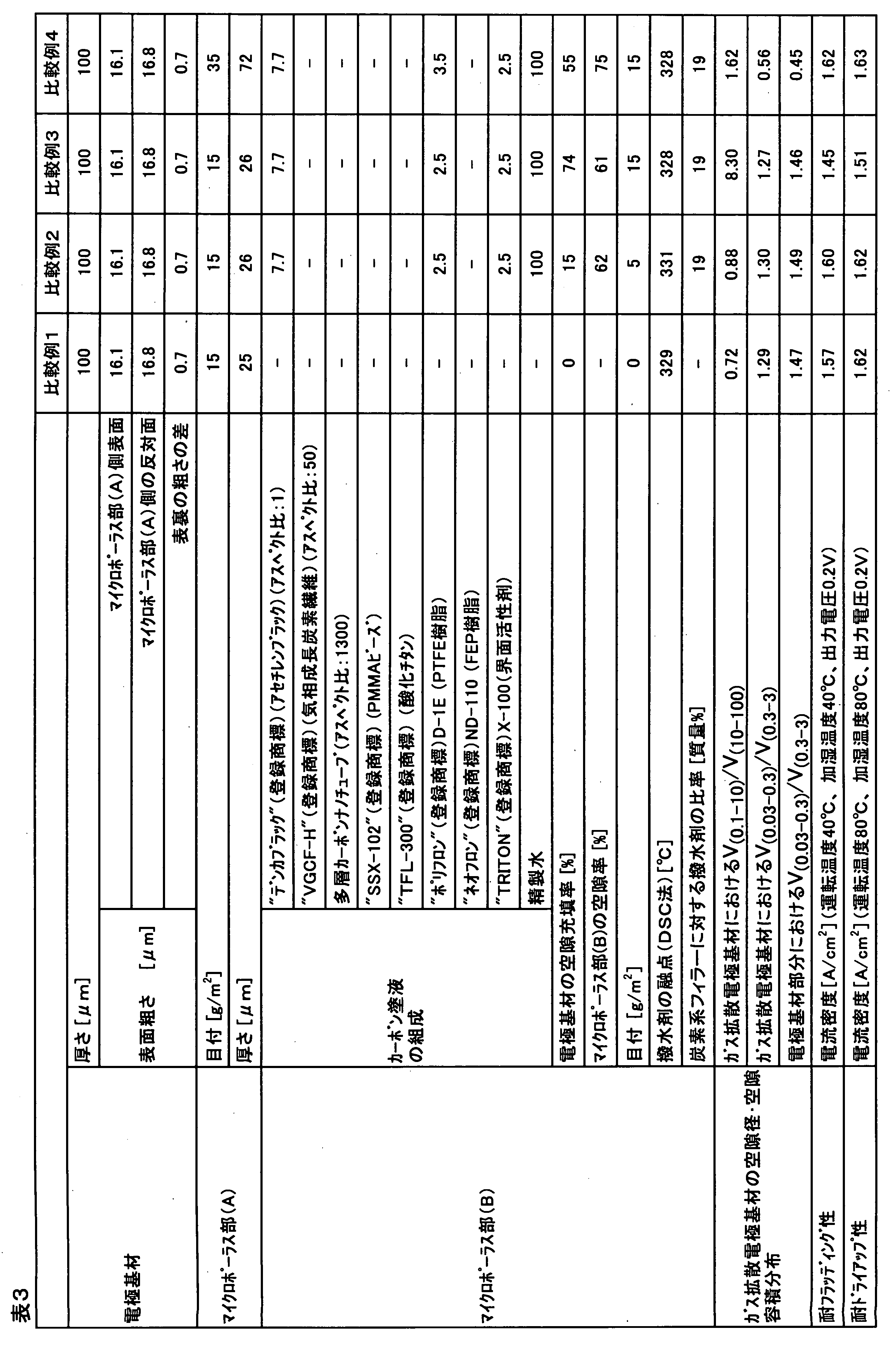
Claims (16)
- 燃料電池に用いられる、電極基材とマイクロポーラス部から構成されるガス拡散電極基材であって、電極基材の片面にマイクロポーラス部(A)が厚さ10μm以上60μm以下の範囲で形成されており、ガス拡散電極基材において、空隙径が0.1μm以上10μm未満である空隙の空隙容積が、空隙径が10μm以上100μm未満である空隙の空隙容積の0.9倍以上5倍以下の範囲内である、ガス拡散電極基材。
- 前記電極基材の厚さが50μm以上190μm以下の範囲である、請求項1に記載のガス拡散電極基材。
- ガス拡散電極基材において、空隙径が0.03μm以上0.3μm未満である空隙の空隙容積が、空隙径が0.3μm以上3μm未満である空隙の空隙容積よりも小さい、請求項1または2に記載のガス拡散電極基材。
- ガス拡散電極基材において、空隙径が0.1μm以上10μm未満である空隙の空隙容積が、空隙径が10μm以上100μm未満である空隙の空隙容積の1倍以上5倍以下の範囲内である、請求項1~3のいずれかに記載のガス拡散電極基材。
- 電極基材の空隙の少なくとも一部にマイクロポーラス部(B)が含浸している構造を持つ、請求項1~4のいずれかに記載のガス拡散電極基材。
- マイクロポーラス部(B)が含浸された電極基材において、空隙径が0.03μm以上0.3μm未満である空隙の空隙容積が、空隙径が0.3μm以上3μm未満である空隙の空隙容積よりも小さい、請求項5に記載のガス拡散電極基材。
- マイクロポーラス部(B)が電極基材自体により形成された空隙の20%以上70%以下を含浸している、請求項5または6に記載のガス拡散電極基材。
- マイクロポーラス部(B)の空隙率が50%以上90%以下の範囲である、請求項5~7のいずれかに記載のガス拡散電極基材。
- マイクロポーラス部(B)の空隙率はマイクロポーラス部(A)の空隙率よりも5%以上大きい、請求項5~8のいずれかに記載のガス拡散電極基材。
- マイクロポーラス部(B)がアスペクト比30以上5000以下のフィラーを含む、請求項5~9のいずれかに記載のガス拡散電極基材。
- 前記フィラーが直径1nm以上500nm以下の繊維状カーボンである、請求項10に記載のガス拡散電極基材。
- マイクロポーラス部(B)に、融点が200℃以上320℃以下である撥水剤を含む、請求項5~11のいずれかに記載のガス拡散電極基材。
- マイクロポーラス部(B)が撥水剤と炭素系フィラーを含み、炭素系フィラーに対し撥水剤の質量比率が5質量%以上50質量%以下である、請求項5~12のいずれかに記載のガス拡散電極基材。
- 電極基材は、マイクロポーラス部(A)が形成される側の表面粗さに対して、その反対側の表面粗さが、1μm以上5μm以下の差を持って大きい、請求項1~13のいずれかに記載のガス拡散電極基材。
- 電解質膜の両側に触媒層を有し、さらに前記触媒層の外側に、請求項1~14のいずれかに記載のガス拡散電極基材を有する、膜電極接合体。
- 請求項15に記載の膜電極接合体の両側にセパレータを有する、燃料電池。
Priority Applications (6)
| Application Number | Priority Date | Filing Date | Title |
|---|---|---|---|
| US15/119,163 US10804544B2 (en) | 2014-02-24 | 2015-02-17 | Gas diffusion electrode substrate, and membrane electrode assembly and fuel cell equipped with same |
| KR1020167021829A KR102082546B1 (ko) | 2014-02-24 | 2015-02-17 | 가스 확산 전극 기재, 및 그것을 구비하는 막 전극 접합체 및 연료 전지 |
| JP2015510563A JP5950031B2 (ja) | 2014-02-24 | 2015-02-17 | ガス拡散電極基材ならびにそれを備える膜電極接合体および燃料電池 |
| EP15752211.1A EP3113264B1 (en) | 2014-02-24 | 2015-02-17 | Gas diffusion electrode substrate, and membrane electrode assembly and fuel cell equipped with the same |
| CN201580010006.XA CN106063009B (zh) | 2014-02-24 | 2015-02-17 | 气体扩散电极基材以及具备其的膜电极接合体及燃料电池 |
| CA2939193A CA2939193C (en) | 2014-02-24 | 2015-02-17 | Gas diffusion electrode substrate, and membrane electrode assembly and fuel cell equipped with same |
Applications Claiming Priority (2)
| Application Number | Priority Date | Filing Date | Title |
|---|---|---|---|
| JP2014-032829 | 2014-02-24 | ||
| JP2014032829 | 2014-02-24 |
Publications (1)
| Publication Number | Publication Date |
|---|---|
| WO2015125749A1 true WO2015125749A1 (ja) | 2015-08-27 |
Family
ID=53878251
Family Applications (1)
| Application Number | Title | Priority Date | Filing Date |
|---|---|---|---|
| PCT/JP2015/054195 Ceased WO2015125749A1 (ja) | 2014-02-24 | 2015-02-17 | ガス拡散電極基材ならびにそれを備える膜電極接合体および燃料電池 |
Country Status (8)
| Country | Link |
|---|---|
| US (1) | US10804544B2 (ja) |
| EP (1) | EP3113264B1 (ja) |
| JP (1) | JP5950031B2 (ja) |
| KR (1) | KR102082546B1 (ja) |
| CN (1) | CN106063009B (ja) |
| CA (1) | CA2939193C (ja) |
| TW (1) | TWI644477B (ja) |
| WO (1) | WO2015125749A1 (ja) |
Cited By (5)
| Publication number | Priority date | Publication date | Assignee | Title |
|---|---|---|---|---|
| KR20180020058A (ko) * | 2016-08-17 | 2018-02-27 | 주식회사 엘지화학 | 전도성 물품의 제조방법 |
| KR20180020454A (ko) * | 2016-08-18 | 2018-02-28 | 주식회사 엘지화학 | 그물구조 전도체의 제조방법 |
| KR20180087291A (ko) * | 2015-12-11 | 2018-08-01 | 도레이 카부시키가이샤 | 탄소 시트, 가스 확산 전극 기재 및 연료 전지 |
| JP2020509552A (ja) * | 2018-01-17 | 2020-03-26 | アウディ アクチェンゲゼルシャフトAudi Ag | 水管理が最適化されたカスケード式燃料電池スタックおよび燃料電池システム |
| WO2023157745A1 (ja) | 2022-02-18 | 2023-08-24 | 東レ株式会社 | 燃料電池用ガス拡散電極 |
Families Citing this family (6)
| Publication number | Priority date | Publication date | Assignee | Title |
|---|---|---|---|---|
| CA2939185A1 (en) * | 2014-02-24 | 2015-08-27 | Toray Industries, Inc. | Gas diffusion electrode substrate, and membrane electrode assembly and fuel cell provided therewith |
| JP6988788B2 (ja) * | 2016-12-05 | 2022-01-05 | 東レ株式会社 | ガス拡散電極とその製造方法 |
| KR102453036B1 (ko) | 2017-01-19 | 2022-10-12 | 도레이 카부시키가이샤 | 가스 확산 전극 및 연료 전지 |
| CA3215413A1 (en) * | 2021-03-31 | 2022-10-06 | Toray Industries, Inc. | Electrode base material and method for producing same |
| CN115000446B (zh) * | 2022-07-22 | 2024-05-31 | 上海电气集团股份有限公司 | 一种气体扩散层及其制备方法、膜电极、电池和应用 |
| KR102568624B1 (ko) * | 2022-12-08 | 2023-08-23 | 주식회사 엔바이오니아 | 연료전지용 기체확산층 및 그 제조방법 |
Citations (7)
| Publication number | Priority date | Publication date | Assignee | Title |
|---|---|---|---|---|
| JP2004124267A (ja) * | 2002-09-30 | 2004-04-22 | Toray Ind Inc | 炭素繊維織物、ガス拡散体、膜−電極接合体および燃料電池 |
| JP2005267902A (ja) * | 2004-03-16 | 2005-09-29 | Aisin Seiki Co Ltd | 固体高分子型燃料電池 |
| JP2007317435A (ja) * | 2006-05-24 | 2007-12-06 | Mitsubishi Electric Corp | 固体高分子型燃料電池およびその製造方法 |
| JP2008311181A (ja) * | 2007-06-18 | 2008-12-25 | Mitsubishi Rayon Co Ltd | 膜電極接合体、その製造方法及び該膜電極接合体を用いた燃料電池 |
| WO2011010339A1 (ja) * | 2009-07-21 | 2011-01-27 | 株式会社 東芝 | 燃料電池 |
| JP2011233274A (ja) * | 2010-04-23 | 2011-11-17 | Japan Vilene Co Ltd | 水分管理シート、ガス拡散シート、膜−電極接合体及び固体高分子形燃料電池 |
| JP2012054111A (ja) * | 2010-09-01 | 2012-03-15 | Dainippon Printing Co Ltd | 導電性多孔質層が形成された固体高分子形燃料電池用ガス拡散層及びそれを用いた固体高分子形燃料電池 |
Family Cites Families (10)
| Publication number | Priority date | Publication date | Assignee | Title |
|---|---|---|---|---|
| US6350539B1 (en) * | 1999-10-25 | 2002-02-26 | General Motors Corporation | Composite gas distribution structure for fuel cell |
| JP5145831B2 (ja) * | 2007-09-12 | 2013-02-20 | 株式会社エクォス・リサーチ | 燃料電池、燃料電池用拡散層及び燃料電池システム。 |
| JP2009129599A (ja) | 2007-11-21 | 2009-06-11 | Toyota Motor Corp | 膜電極積層体および膜電極積層体を備える燃料電池 |
| JP2009238376A (ja) | 2008-03-25 | 2009-10-15 | Equos Research Co Ltd | 燃料電池 |
| JP5481820B2 (ja) * | 2008-10-03 | 2014-04-23 | 日産自動車株式会社 | マイクロポーラス層およびこれを有するガス拡散層 |
| JP2011243314A (ja) * | 2010-05-14 | 2011-12-01 | Honda Motor Co Ltd | 固体高分子型燃料電池用膜電極構造体 |
| WO2011149442A1 (en) * | 2010-05-24 | 2011-12-01 | Utc Power Corporation | Fuel cell having a hydrophilic nanoporous region |
| CN102456891B (zh) * | 2010-10-29 | 2014-07-23 | 中国科学院大连化学物理研究所 | 一种具有梯度孔结构的气体扩散层及其制备和应用 |
| US9692070B2 (en) * | 2012-06-29 | 2017-06-27 | Jntg Co., Ltd. | Carbon substrate for gas diffusion layer, gas diffusion layer using the same, and electrode for fuel cell, membrane-electrode assembly and fuel cell comprising the gas diffusion layer |
| KR102121822B1 (ko) * | 2012-08-24 | 2020-06-11 | 도레이 카부시키가이샤 | 연료 전지용 가스 확산 전극 기재 |
-
2015
- 2015-02-17 CN CN201580010006.XA patent/CN106063009B/zh active Active
- 2015-02-17 KR KR1020167021829A patent/KR102082546B1/ko active Active
- 2015-02-17 TW TW104105483A patent/TWI644477B/zh not_active IP Right Cessation
- 2015-02-17 US US15/119,163 patent/US10804544B2/en active Active
- 2015-02-17 CA CA2939193A patent/CA2939193C/en active Active
- 2015-02-17 JP JP2015510563A patent/JP5950031B2/ja active Active
- 2015-02-17 WO PCT/JP2015/054195 patent/WO2015125749A1/ja not_active Ceased
- 2015-02-17 EP EP15752211.1A patent/EP3113264B1/en active Active
Patent Citations (7)
| Publication number | Priority date | Publication date | Assignee | Title |
|---|---|---|---|---|
| JP2004124267A (ja) * | 2002-09-30 | 2004-04-22 | Toray Ind Inc | 炭素繊維織物、ガス拡散体、膜−電極接合体および燃料電池 |
| JP2005267902A (ja) * | 2004-03-16 | 2005-09-29 | Aisin Seiki Co Ltd | 固体高分子型燃料電池 |
| JP2007317435A (ja) * | 2006-05-24 | 2007-12-06 | Mitsubishi Electric Corp | 固体高分子型燃料電池およびその製造方法 |
| JP2008311181A (ja) * | 2007-06-18 | 2008-12-25 | Mitsubishi Rayon Co Ltd | 膜電極接合体、その製造方法及び該膜電極接合体を用いた燃料電池 |
| WO2011010339A1 (ja) * | 2009-07-21 | 2011-01-27 | 株式会社 東芝 | 燃料電池 |
| JP2011233274A (ja) * | 2010-04-23 | 2011-11-17 | Japan Vilene Co Ltd | 水分管理シート、ガス拡散シート、膜−電極接合体及び固体高分子形燃料電池 |
| JP2012054111A (ja) * | 2010-09-01 | 2012-03-15 | Dainippon Printing Co Ltd | 導電性多孔質層が形成された固体高分子形燃料電池用ガス拡散層及びそれを用いた固体高分子形燃料電池 |
Cited By (10)
| Publication number | Priority date | Publication date | Assignee | Title |
|---|---|---|---|---|
| KR20180087291A (ko) * | 2015-12-11 | 2018-08-01 | 도레이 카부시키가이샤 | 탄소 시트, 가스 확산 전극 기재 및 연료 전지 |
| KR102630169B1 (ko) * | 2015-12-11 | 2024-01-29 | 도레이 카부시키가이샤 | 탄소 시트, 가스 확산 전극 기재 및 연료 전지 |
| KR20180020058A (ko) * | 2016-08-17 | 2018-02-27 | 주식회사 엘지화학 | 전도성 물품의 제조방법 |
| KR102063059B1 (ko) * | 2016-08-17 | 2020-01-07 | 주식회사 엘지화학 | 전도성 물품의 제조방법 |
| KR20180020454A (ko) * | 2016-08-18 | 2018-02-28 | 주식회사 엘지화학 | 그물구조 전도체의 제조방법 |
| KR102126679B1 (ko) | 2016-08-18 | 2020-06-25 | 주식회사 엘지화학 | 그물구조 전도체의 제조방법 |
| JP2020509552A (ja) * | 2018-01-17 | 2020-03-26 | アウディ アクチェンゲゼルシャフトAudi Ag | 水管理が最適化されたカスケード式燃料電池スタックおよび燃料電池システム |
| US11201346B2 (en) | 2018-01-17 | 2021-12-14 | Audi Ag | Cascaded fuel cell stack and fuel cell system |
| WO2023157745A1 (ja) | 2022-02-18 | 2023-08-24 | 東レ株式会社 | 燃料電池用ガス拡散電極 |
| KR20240148803A (ko) | 2022-02-18 | 2024-10-11 | 도레이 카부시키가이샤 | 연료전지용 가스 확산 전극 |
Also Published As
| Publication number | Publication date |
|---|---|
| EP3113264A1 (en) | 2017-01-04 |
| CN106063009A (zh) | 2016-10-26 |
| JPWO2015125749A1 (ja) | 2017-03-30 |
| TW201547097A (zh) | 2015-12-16 |
| US10804544B2 (en) | 2020-10-13 |
| CA2939193C (en) | 2022-03-08 |
| KR102082546B1 (ko) | 2020-02-27 |
| EP3113264B1 (en) | 2018-07-04 |
| US20170012297A1 (en) | 2017-01-12 |
| CN106063009B (zh) | 2019-05-03 |
| EP3113264A4 (en) | 2017-08-09 |
| JP5950031B2 (ja) | 2016-07-13 |
| CA2939193A1 (en) | 2015-08-27 |
| TWI644477B (zh) | 2018-12-11 |
| KR20160124097A (ko) | 2016-10-26 |
Similar Documents
| Publication | Publication Date | Title |
|---|---|---|
| JP5950031B2 (ja) | ガス拡散電極基材ならびにそれを備える膜電極接合体および燃料電池 | |
| JP6206186B2 (ja) | 燃料電池用ガス拡散電極基材 | |
| JP5835527B1 (ja) | ガス拡散電極基材ならびにそれを備える膜電極接合体および燃料電池 | |
| JP6489009B2 (ja) | ガス拡散電極基材 | |
| JP6070889B2 (ja) | 炭素シート、ガス拡散電極基材および燃料電池 | |
| JP6205718B2 (ja) | 燃料電池ガス拡散層、膜電極接合体、および燃料電池 | |
| JP6330282B2 (ja) | 燃料電池用ガス拡散電極基材およびその製造方法 | |
| WO2016076132A1 (ja) | ガス拡散電極基材およびガス拡散電極基材の製造方法 | |
| WO2023190153A1 (ja) | ガス拡散電極、燃料電池および輸送用機器 | |
| JPWO2017099181A1 (ja) | 炭素シート、ガス拡散電極基材、および燃料電池 | |
| WO2017069014A1 (ja) | 炭素シート、ガス拡散電極基材、巻回体、および燃料電池 |
Legal Events
| Date | Code | Title | Description |
|---|---|---|---|
| ENP | Entry into the national phase |
Ref document number: 2015510563 Country of ref document: JP Kind code of ref document: A |
|
| 121 | Ep: the epo has been informed by wipo that ep was designated in this application |
Ref document number: 15752211 Country of ref document: EP Kind code of ref document: A1 |
|
| ENP | Entry into the national phase |
Ref document number: 2939193 Country of ref document: CA |
|
| ENP | Entry into the national phase |
Ref document number: 20167021829 Country of ref document: KR Kind code of ref document: A |
|
| REEP | Request for entry into the european phase |
Ref document number: 2015752211 Country of ref document: EP |
|
| WWE | Wipo information: entry into national phase |
Ref document number: 2015752211 Country of ref document: EP |
|
| WWE | Wipo information: entry into national phase |
Ref document number: 15119163 Country of ref document: US |
|
| NENP | Non-entry into the national phase |
Ref country code: DE |