WO2015126155A1 - 에어커텐을 이용한 솔더볼 공급장치 - Google Patents
에어커텐을 이용한 솔더볼 공급장치 Download PDFInfo
- Publication number
- WO2015126155A1 WO2015126155A1 PCT/KR2015/001624 KR2015001624W WO2015126155A1 WO 2015126155 A1 WO2015126155 A1 WO 2015126155A1 KR 2015001624 W KR2015001624 W KR 2015001624W WO 2015126155 A1 WO2015126155 A1 WO 2015126155A1
- Authority
- WO
- WIPO (PCT)
- Prior art keywords
- housing
- ball
- solder ball
- mask
- gas
- Prior art date
- Legal status (The legal status is an assumption and is not a legal conclusion. Google has not performed a legal analysis and makes no representation as to the accuracy of the status listed.)
- Ceased
Links
Images








Classifications
-
- H—ELECTRICITY
- H10—SEMICONDUCTOR DEVICES; ELECTRIC SOLID-STATE DEVICES NOT OTHERWISE PROVIDED FOR
- H10W—GENERIC PACKAGES, INTERCONNECTIONS, CONNECTORS OR OTHER CONSTRUCTIONAL DETAILS OF DEVICES COVERED BY CLASS H10
- H10W72/00—Interconnections or connectors in packages
- H10W72/01—Manufacture or treatment
- H10W72/011—Apparatus therefor
- H10W72/0112—Apparatus for manufacturing bump connectors
-
- B—PERFORMING OPERATIONS; TRANSPORTING
- B23—MACHINE TOOLS; METAL-WORKING NOT OTHERWISE PROVIDED FOR
- B23K—SOLDERING OR UNSOLDERING; WELDING; CLADDING OR PLATING BY SOLDERING OR WELDING; CUTTING BY APPLYING HEAT LOCALLY, e.g. FLAME CUTTING; WORKING BY LASER BEAM
- B23K3/00—Tools, devices or special appurtenances for soldering, e.g. brazing, or unsoldering, not specially adapted for particular methods
- B23K3/06—Solder feeding devices; Solder melting pans
- B23K3/0607—Solder feeding devices
- B23K3/0623—Solder feeding devices for shaped solder piece feeding, e.g. preforms, bumps, balls, pellets, droplets
-
- H—ELECTRICITY
- H10—SEMICONDUCTOR DEVICES; ELECTRIC SOLID-STATE DEVICES NOT OTHERWISE PROVIDED FOR
- H10W—GENERIC PACKAGES, INTERCONNECTIONS, CONNECTORS OR OTHER CONSTRUCTIONAL DETAILS OF DEVICES COVERED BY CLASS H10
- H10W72/00—Interconnections or connectors in packages
- H10W72/01—Manufacture or treatment
- H10W72/012—Manufacture or treatment of bump connectors, dummy bumps or thermal bumps
- H10W72/01221—Manufacture or treatment of bump connectors, dummy bumps or thermal bumps using local deposition
- H10W72/01225—Manufacture or treatment of bump connectors, dummy bumps or thermal bumps using local deposition in solid form, e.g. by using a powder or by stud bumping
-
- H—ELECTRICITY
- H10—SEMICONDUCTOR DEVICES; ELECTRIC SOLID-STATE DEVICES NOT OTHERWISE PROVIDED FOR
- H10W—GENERIC PACKAGES, INTERCONNECTIONS, CONNECTORS OR OTHER CONSTRUCTIONAL DETAILS OF DEVICES COVERED BY CLASS H10
- H10W72/00—Interconnections or connectors in packages
- H10W72/01—Manufacture or treatment
- H10W72/0198—Manufacture or treatment batch processes
Definitions
- the present invention relates to a solder ball supply device used in ball bumping equipment for attaching solder balls to wafers or similar materials. Specifically, the present invention relates to a solder ball supply device using an air curtain to prevent solder balls from escaping to the outside of the housing, The present invention relates to a solder ball supply device capable of more effectively injecting solder balls into a mask hole by gently pressing a solder ball on an upper surface of a ball mask using a pressing member.
- a predetermined thin film is deposited on a wafer, and the deposited thin film must be formed through a photolithography and etching process to form a circuit pattern.
- the wafer is divided into individual dies, and then a packaging process is performed for each die.
- a wafer bumping method of attaching a plurality of solder balls to the front surface of a wafer at a time by using a mask before cutting the wafer has been widely used.
- the conventional wafer bumping method of the related art proceeds in the following order.
- the flux mask 20 is positioned above the wafer W while the wafer W is placed on the chuck 10. Subsequently, when the flux F is squeezed from the upper portion of the flux mask 20 to the blade 22, the flux F passing through the mask hole of the flux mask 20 is dotting to a predetermined position of the wafer W. do.
- the ball mask 30 is positioned on the wafer W, and then the solder ball B is poured on the ball mask 30. Subsequently, the solder balls B are sufficiently dispersed in the upper portion of the ball mask 30 using the brush 32 so that the solder balls B pass through the mask hole.
- Japanese Laid-Open Patent Publication No. 2010-177230 introduces a so-called cyclone-type solder ball supply device in which a circular air blowing device is installed around a hopper.
- This method has the advantage that a smaller number of balls can be used than the conventional ones because the solder balls are not dispersed around the substrate.
- the solder balls entering the mask hole due to the strong wind pressure of the air ejecting device are pulled out again. There is a risk of coming out.
- the impact and the amount of impact of the solder ball is increased by the strong wind pressure may damage the solder ball may cause product defects.
- Korean Patent No. 10-1116937 introduces a solder ball printing apparatus in which a wire rod having a line spacing smaller than the diameter of the solder ball is installed under the solder ball supply unit.
- the vibration must be generated after supplying the solder ball on the upper part of the wire rod, and therefore, a vibrator must be installed.
- the agitator not only accelerates the deterioration of the solder ball printing apparatus when used for a long time, but also increases the cost of the product.
- the vibration is applied while the lower end of the wire is in contact with the mask surface, the service life of the wire is shortened due to contact friction.
- the line spacing must be constant. Therefore, the solder ball is not uniformly distributed on the mask, there is a problem that the solder ball is not stably injected into the mask hole.
- Patent Document 1 Japanese Patent Laid-Open No. 2010-177230 (published date: 2010.8.12)
- Patent Document 2 Korean Registered Patent No. 10-1116937 (Notice Date: 2012.3.12)
- An object of the present invention is to provide a solder ball supply device which can more stably input the solder ball in the mask hole in the ball bumping process.
- an object of the present invention is to provide a solder ball supply apparatus that can reduce the cost and increase the productivity by reducing the amount and loss of solder balls and the time that the solder ball is put into the mask hole.
- a solder ball supply apparatus for performing a ball bumping process while supplying a solder ball to the upper portion of the ball mask, the lower housing is open; A rotating shaft coupled to the center of the housing; A pressing member fixed to the inside of the housing to evenly distribute the solder balls on the ball mask and to lightly press the solder balls located on the ball mask into the ball holes of the ball mask; An air curtain portion for injecting gas into the housing to prevent the solder ball from escaping out of the housing; It provides a solder ball supply device including a rotation drive means for rotating the housing and the pressing member by rotating the rotary shaft.
- Solder ball supply apparatus may include at least one of the horizontal driving means for moving the housing in the horizontal direction and the vertical driving means for moving in the vertical direction.
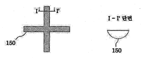
- the pressing member may be characterized in that the shape seen from the bottom surface is straight or cross-shaped, the shape of the side cross-section is circular, arc or straight.
- the air curtain portion, the flow path formed in the ceiling and the side wall of the housing Gas supply means for supplying gas to the flow path; It may be characterized in that it comprises a spray nozzle formed on the side wall of the housing to inject gas toward the interior of the housing, symmetrical with respect to the center of rotation of the housing and in communication with the flow path.
- the through-hole is formed in the center
- the bottom surface includes a ring-shaped guide means formed with a plurality of guide flow paths for the gas injected from the outlet of the injection nozzle portion
- the guide flow passage may be formed in a direction crossing the direction toward the center of rotation of the housing.
- a solder ball supply apparatus for performing a ball bumping process while supplying a solder ball to an upper portion of a ball mask, the lower opening of a housing;
- a rotating shaft coupled to the center of the housing;
- a pressing member fixed to the inside of the housing to evenly distribute the solder balls on the ball mask and to lightly press the solder balls located on the ball mask into the ball holes of the ball mask;
- a first injection nozzle part which forms an air flow by injecting gas into the inside of the housing so that the solder ball does not escape out of the housing;
- An air curtain portion for forming an air curtain on the outside of the first injection nozzle portion, the air curtain portion including a second injection nozzle portion having an outlet formed at a lower end of the side wall of the housing at a position surrounding the outside of the first injection nozzle portion; It provides a solder ball supply device including a rotation drive means for rotating the housing and the pressing member by rotating the rotary shaft.
- the through portion is formed in the center
- the bottom surface includes a ring-shaped guide means formed with a plurality of guide flow paths for the gas injected from the outlet of the first injection nozzle portion,
- the guide flow path may be formed in a direction crossing the direction toward the center of rotation of the housing.
- the inner wall of the guide means is a first inclined surface is smaller diameter as the upper side, and the second is located on the upper side of the first inclined surface and the larger diameter It may be characterized by including an inclined surface.
- the first injection nozzle portion may be formed to inject gas in a direction intersecting with the direction toward the center of rotation of the housing.
- the inner wall of the housing is a gas flow guide protruding inward
- the gas flow guide may include an inclined surface lowered toward the outside inward.
- At least one of the side wall and the ceiling of the housing may be characterized in that the gas outlet for discharging the gas supplied to the outside to the outside.
- the solder ball injected into the upper portion of the mask is not only distributed evenly by the pressing member, but also pushed into the pressing member or slightly pressed into the mask hole.
- solder ball is continuously maintained in the ball holding area at the center of the housing by the gas injected from the outside of the housing, it is possible to proceed with a more efficient ball bumping process using a smaller amount of solder balls than in the prior art.
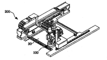
- Figure 2 is a perspective view of a ball bumping equipment equipped with a solder ball supply apparatus according to a first embodiment of the present invention
- 3 and 4 are a perspective view and a bottom perspective view of a solder ball supply device according to a first embodiment of the present invention, respectively
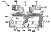
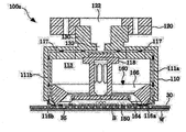
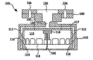
- FIG. 5 is a cross-sectional view of a solder ball supply device according to a first embodiment of the present invention.
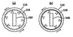
- FIG. 6 is a view showing several types of injection nozzles
- FIG 7 and 8 are process cross-sectional views sequentially showing the operation of the solder ball supply apparatus according to the first embodiment of the present invention, respectively.
- FIG 9 is a view illustrating a movement path of the housing in the upper part of the ball mask.
- FIG. 10 is a perspective view of a solder ball supply device according to a second embodiment of the present invention.
- FIG. 11 is a cross-sectional view of a solder ball supply apparatus according to a second embodiment of the present invention.
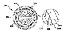
- FIG. 12 is a bottom view of a solder ball supply device according to a second embodiment of the present invention.
- FIG. 13 is a process cross-sectional view showing the operation of the solder ball supply apparatus according to a second embodiment of the present invention.
- 14 to 16 is a bottom perspective view, a cross-sectional view and a process cross-sectional view showing a modification of the solder ball supply apparatus according to an embodiment of the present invention, respectively
- the present invention relates to a solder ball supply apparatus, and the scope of the present invention is not limited to wafer bumping.
- wafer bumping all materials including solder wafer bumping will be referred to as 'substrates'.
- the solder ball supply device 100 constitutes a part of the ball bumping equipment 200 as illustrated in FIG. 2, and is lifted by a vertical driving means provided in the ball bumping equipment 200. And descending and supplying solder balls to the upper portion of the ball mask 30 while moving in the horizontal direction by the horizontal driving means.
- solder ball supply apparatus 100 according to a first embodiment of the present invention will be described with reference to the drawings.
- Solder ball supply apparatus 100 according to the first embodiment of the present invention, as shown in a perspective view of Figure 3, a bottom perspective view of Figure 4 and a cross-sectional view of Figure 5, the fixing bracket 102, the lower end of the fixing bracket 102 A support frame 120 fixed to the housing, a housing 110 rotatably coupled to the lower portion of the support frame 120, and installed in the inner center of the housing 110 to press the evenly distributed solder balls to the upper part of the ball mask.
- the member 150 is included.
- the fixing bracket 102 serves to mount the solder ball supplying device 100 to the vertical driving means or the horizontal driving means of the ball bumping equipment (200 of FIG. 2), and the support frame 120 can rotate the housing 110. To support them.
- the upper portion of the support frame 120 is provided with a rotation driving means 104 such as a motor for rotating the housing 110.
- the rotating shaft 130 is rotatably coupled to the center of the support frame 120, the rotating shaft 130 may be directly connected to the rotary driving means 104, using a power transmission means such as a belt, gear, wire, chain It may also be indirectly connected.
- a power transmission means such as a belt, gear, wire, chain It may also be indirectly connected.
- a gas supply passage 132 is formed inside the rotation shaft 130, and the gas supply passage 132 communicates with a flow path 111 formed on the ceiling of the housing 110 to be described later.
- a gas supply port (not shown) may be mounted at an upper end of the gas supply passage 132, and the gas supply port may be installed inside the through part 122 formed at the center of the support frame 120. .
- the housing 110 has an inverted cylindrical shape with an open bottom, and is coupled to a lower end of the rotation shaft 130 protruding from the lower portion of the support frame 120 at the center of the ceiling.
- the housing 110 is provided with a means for preventing the solder ball from escaping the outside of the housing by forming an air curtain by injecting gas into the interior of the housing.
- the flow path 111 communicating with the gas supply passage 132 of the rotation shaft 130 is formed in the ceiling and the sidewall of the housing 110.
- the flow path 111 formed on the ceiling of the housing 110 is shown in the horizontal direction, and the flow path 111 formed in the sidewall is shown in the vertical direction, but is not necessarily limited thereto.
- the flow paths 111 formed on the ceiling and the sidewalls of the housing 110 may include various paths for uniform gas injection. If necessary, the flow paths of a specific position may be formed without forming the flow paths 111 to a constant diameter. 111 may be formed to be different from the diameter of other portions.
- an injection nozzle part 116 is formed at the lower end of the inner wall of the housing 110 to inject the gas supplied through the flow path 111 into the housing 110.
- the outlet of the injection nozzle unit 116 may be formed at the bottom of the inner wall of the housing 110, or may be formed at the corner between the inner wall and the bottom surface.
- a plurality of gas outlets 117 are formed symmetrically on the ceiling of the housing 110 to discharge the gas supplied into the outside.
- a plurality of gas outlets 114 are symmetrically formed on the sidewall of the housing 110, but the gas outlet 114 of the sidewall may be omitted.
- the gas outlet 117 When the gas outlet 117 is formed in this way, the gas injected into the interior of the housing 110 through the injection nozzle unit 116 rises while rotating in the internal space 113 of the housing, and a part of the gas outlet 114 of the side wall.
- the outside may be discharged to the outside through the gas outlet 117 of the ceiling and the rest may be discharged to the outside.
- a plurality of through holes 124 may be formed in the support frame 120 at a position corresponding to the gas outlet 117 of the ceiling of the housing 110 for smoother gas discharge.
- a ball supply pipe (not shown) may be installed at one of the gas outlets 117 of the gas outlets 117 formed on the ceiling of the housing 110.
- the present invention is not limited thereto, and the ball supply pipe may be installed at another position.
- the upper end of the pressing member 150 is fixed to the center of the ceiling of the housing 110 through the fixing member 118, and thus rotates together when the housing 110 rotates.
- the pressing member 150 is fixed to the housing 110 such that the lower end contacts the upper portion of the ball mask or is spaced apart by a small distance when the housing 110 is lowered for the ball bumping process.
- the pressing member 150 serves to push and disperse the solder ball supplied to the upper portion of the ball mask while gently pushing the upper end of the solder ball into the mask hole of the ball mask.
- the pressing member 150 when the pressing member 150 is rotated by placing the circular tubular pressing member 150 having both ends open in the horizontal direction in the housing 110, the solder ball is pushed against the outer wall of the circular tube. To move.
- the shape of the pressing member 150 is not necessarily limited thereto, which will be described later.
- the pressing member 150 may be made of various materials such as metal, plastic, vinyl, paper.
- the pressing member 150 may be made of various materials such as metal, plastic, vinyl, paper.
- a SUS plate having a thickness of 0.03 to 0.05 mm is processed into a predetermined shape and used as a pressing member, since the thickness is thin, almost no damage occurs even when contacting the solder ball (B).
- the pressing member 150 serves to evenly distribute the solder ball to the upper part of the ball mask 30, press or push near the upper end of the solder ball flowing in the upper portion of the ball mask 30 solder ball mask hole of the ball mask (30) To be effective in
- the injection nozzle unit 116 is preferably formed symmetrically with respect to the center of rotation of the housing 110.
- the injection nozzle unit 116 may be formed of a plurality of holes as illustrated in FIG. 6A, or may be formed in a slit form as shown in FIG. 6B.
- the diameter is preferably 0.3 mm or less and is formed at intervals of about 10 degrees.
- the width of the outlet is preferably 0.05 mm or less, but is not necessarily limited thereto.
- the injection nozzle unit 116 may be symmetrically disposed with respect to the center of the housing 110.
- the injection nozzle unit 116 is preferably formed to be slightly inclined downward rather than in a horizontal direction, and particularly preferably formed to have an angle of 5 to 45 degrees with respect to the surface of the ball mask 30.
- the present invention is not necessarily limited thereto, and may be formed in a horizontal direction as necessary.
- the injection nozzle unit 116 may be formed such that the injection direction is toward the center of the housing 110, or may be formed to be inclined in the circumferential direction with respect to the center of the housing 110.
- Gas such as nitrogen and air, supplied through the gas supply passage 132 of the rotary shaft 130, passes through the housing 110 through the injection nozzle part 116 formed at the lower side of the side wall through the ceiling and the flow path 111 of the side wall. It is sprayed into the interior of the 110, and as the housing 110 rotates, as the vortex flow occurs inside the housing 110, the solder balls therein are collected into the ball holding area.
- a plurality of gas outlets 117 and 114 are formed on the ceiling and the sidewall of the housing 110, respectively, so that the gas inside the housing is naturally exhausted.
- a mechanical configuration can be added to elevate the gas supplied therein.
- a gas flow guide 119 having an inclined surface that is lowered toward the center may be formed near the lower end of the inner wall of the housing 110.
- the gas flow guide 119 serves to push up the air inside when the housing 110 rotates, so that the air inside the air flows more smoothly through the gas outlets 117 and 114 of the ceiling and sidewalls. It becomes possible.
- the inclined surface of the gas flow guide 119 may be flat or curved.
- the flux is doped into the bumping area of the substrate W, and then the ball mask 30 is positioned on the substrate W for the ball bumping process.
- the ball mask 30 is fixed to the mask support, and the substrate W is positioned below the ball mask 30.
- the ball mask 30 includes a hole pattern in which a plurality of mask holes 35 are formed in the center, and the hole pattern corresponds to the bumping area of the substrate W. As shown in FIG. 7, the ball mask 30 includes a hole pattern in which a plurality of mask holes 35 are formed in the center, and the hole pattern corresponds to the bumping area of the substrate W. As shown in FIG. 7, the hole pattern corresponds to the bumping area of the substrate W.
- the horizontal drive means and the vertical drive means are selectively driven to move the solder ball supply device 100 to the process start position on the upper side of the ball mask 30.
- the distance between the lower sidewall of the housing 110 and the ball mask 30 should be smaller than the diameter of the solder ball (B).
- the spacing between the lowest point of the pressing member 150 installed in the housing 110 and the ball mask 30 is not particularly limited, but the pressing member 150 slightly presses the upper portion of the solder ball B to close the ball mask 30. Maintain a gap that can be pushed into the mask hole 35 of) or by pressing the solder balls (B) stacked on the upper portion of the ball mask (30) from the top to the lower solder ball (B) is pushed into the mask hole (35) Leave enough space to enter.
- solder ball B is supplied into the housing 110 through a ball supply pipe (not shown).
- gas eg, nitrogen
- the supplied gas opens the flow path 111 formed on the ceiling and the sidewall of the housing 110.
- injection nozzle unit 116 of the lower end is injected into the housing 110.
- the pressing member 150 fixed to the housing 110 is also rotated together, and the solder balls B placed on the ball mask 30 are pressed into the empty mask holes 35, and the solder balls B stuck together.
- the ball mask 30 is evenly distributed over the top.
- the dispersed solder ball B is continuously pushed toward the inner center of the housing 110 by being pushed by the injected gas, and is then introduced into the mask hole 35 by the pressing member 150 or dispersed again.
- the solder ball B injected into the mask hole 35 is attached to the flux F doped on the substrate W.
- the gas injected into the interior of the housing 110 is rotated and rotates through the internal space 113 of the housing 110 and then rises through the gas outlets 114 and 117 formed on the side wall and the ceiling of the housing 110. It is discharged to the outside.
- the solder ball supply device 100 may perform a ball bumping process while rotating in a stopped state on the upper portion of the ball mask 30.
- the ball bumping process should be performed while moving the solder ball supply apparatus 100 on the upper portion of the substrate (W).
- the solder ball supply device 100 it is preferable to perform the ball bumping process while moving the solder ball supply device 100 so that the housing 110 covers all of the hole patterns of the ball mask 30. More preferably, the solder ball supply device 100 is moved so that the ball holding area formed inside the housing 110 covers all of the hole patterns of the ball mask 30, thereby moving the solder ball to the hole pattern of the ball mask 30. This should be supplied without exception.
- the solder ball supply device 100 After moving as described above, the solder ball supply device 100 completely removes the hole pattern of the ball mask 30, and then the residual solder ball B should be removed.
- the remaining solder ball may be removed by a separate suction means, and the suction means may be lifted on the outer wall of the housing 110 of the solder ball supply device 100 to remove the residual solder ball more conveniently. It can also be installed.
- the suction means In the case of installing in the housing 110, after the solder ball supply device 100 which has been processed is slightly raised, the suction means is lowered to the surface of the ball mask 30, and the solder ball supply device 100 is moved in the horizontal direction. Vacuum suction.
- FIGS. 10 to 12 are respectively a perspective view, a cross-sectional view and a bottom view of a solder ball supply device 100a according to a second embodiment of the present invention
- Figure 13 is a cross-sectional view showing a solder ball bumping process using the same.
- the solder ball supply device 100a also has the fixing bracket 102, the support frame 120 fixed to the lower end of the fixing bracket 102, and the support frame 120, like the first embodiment.
- the housing 110 is rotatably coupled to the bottom of the) and the pressing member 150 is installed in the inner center of the housing 110 to evenly distribute the solder ball to the upper portion of the ball mask.
- a second injection nozzle formed at an outer side of the first injection nozzle unit 116a and the first injection nozzle unit 116a at the lower end of the side wall of the housing 110 to inject gas toward the inside of the housing 110.
- the guide means 160 for guiding the movement of the gas injected from the first and second injection nozzle unit 116a is formed in the housing 110 is different from the first embodiment.
- the first injection nozzle unit 116a may be formed at the lower end of the inner wall of the housing 110 like the injection nozzle unit 116 of the first embodiment, or may be formed at the edge between the inner wall and the bottom surface. It may be.
- the second injection nozzle part 116b is formed on the bottom surface of the side wall of the housing 110 at the outside of the first injection nozzle part 116a, so that the second injection nozzle part 116b is formed of the first injection nozzle part 116a. It surrounds the outside.
- the outlets of the first and second injection nozzle parts 116a and 116b may be formed in the form of a plurality of holes arranged in a ring shape, like the injection nozzle part 116 of the first embodiment, respectively, or in the form of a slit. It may be formed.
- first and second injection nozzle parts 116a and 116b are preferably formed symmetrically with respect to the center of rotation of the housing 110, respectively.
- first and second injection nozzles 116a and 116b are preferably formed to be slightly inclined downward, but are not necessarily limited thereto.
- the gas injected from the first injection nozzle unit 116a passes through the guide channel 162 formed on the bottom surface of the guide means 160, and the traveling direction is changed to generate a vortex flow inside the housing 110. It serves to keep the solder ball inside the ball holding area.
- the gas injected from the second injection nozzle part 116b proceeds to the center of the housing 110 through the lower part of the side wall of the housing 110 and the lower part of the guide means 160, and the solder ball flows out of the housing 110. It acts as an air curtain to prevent it from being prevented.
- the second injection nozzle unit 116b may generate a significant vortex by injecting the gas obliquely toward the upper surface of the mask, the injected gas passes through the sidewall of the housing 110 and the lower portion of the guide means 160. Because the eddy current can be extinguished or minimized, it is possible to maintain a stable vortex flow inside the housing 110.
- the first injection nozzle part 116a and the second injection nozzle part 116a and 116b which are formed in the same manner as the second embodiment of the present invention, have the injection nozzle part 116 as a single line. Compared to the case formed, it is possible to reduce the vortex inside the housing 110 and thereby to maintain the solder ball more stably in the ball holding area.
- the first injection nozzle part 116a and the second injection nozzle part 116b are formed at the lower ends of the first flow path 111a and the second flow path 111b formed independently of each other. This is to independently control the gas injection pressure of the first injection nozzle unit 116a and the second injection nozzle unit 116b.
- the present invention is not limited thereto, and one flow path may be branched to connect to the first injection nozzle unit 116a and the second injection nozzle unit 116b.
- the gas injection pressure of the first injection nozzle unit 116a and the second injection nozzle unit 116b may be the same or may be different from each other.
- two gas supply passages 132 may be formed in the rotation shaft 130 to communicate with the first flow passage 111a and the second flow passage 111b, respectively, and one gas supply passage 132 may include the first flow passage (132). It is also possible to communicate with both the 111a) and the second flow path 111b.
- the guide means 160 formed in the solder ball supply device 100a according to the second embodiment of the present invention guides the movement of the gas injected from the first and second injection nozzle parts 116a and 116b. Play a role.
- the guide means 160 may be manufactured separately and mounted on the inner wall of the housing 110, or the sidewall of the housing 110 may be manufactured in the shape of the guide means 160.
- a ring-shaped guide means 160 having a penetrating portion formed in the center thereof was manufactured and fixed to the inner wall of the housing 110.
- the outer wall of the guide means 160 may be detachably coupled to the inner wall of the housing 110, or may be integrally coupled.
- the pressing member 150 is installed to be located inside the through portion of the guide means 160.
- a plurality of guide passages 162 having a groove shape are formed at the bottom of the guide means 160, and each guide passage 162 extends from the outer wall to the inner wall of the guide means 160.
- Each guide flow path 162 is preferably formed in a horizontal direction, but is not limited thereto.
- the plurality of guide flow passages 162 correspond one-to-one with the plurality of first injection nozzle portions 116a formed in the housing 110, and specifically, one end of each guide flow passage 162 may be the first injection nozzle portion 116a. Is located in front of the exit.
- the plurality of guide passages 162 are not formed to face the center of the housing 110, but are formed in a direction intersecting at a predetermined angle with a direction toward the center of rotation of the housing 110 as shown in the bottom view of FIG. 12. It is desirable to be.
- the gas injected from the first injection nozzle unit 116a enters the interior of each of the guide flow paths 162, and then the traveling direction is changed to be injected into the interior of the housing 110.
- the circumferential vortex flow is generated inside the.
- the guide passage 162 preferably has an inlet adjacent to the first injection nozzle part 116a relatively wider than the outlet. This is because even if the speed of the gas is lowered in the process of entering the guide flow path 162 can be increased to some extent the speed injected into the housing 110.
- the inner wall of the guide means 160 includes a first inclined surface 164 that decreases in diameter toward the top and a second inclined surface 166 that is positioned in an upper portion of the first inclined surface 164 and increases in diameter upward. Therefore, when viewed from above, the boundary between the first inclined surface 164 and the second inclined surface 166 surrounds the through part.
- the diameter of the penetrating portion is preferably larger than the length of the pressing member 150 located below, but is not necessarily limited thereto.
- the first inclined surface 164 serves to suppress the gas injected into the guide means 160 does not immediately rise, thereby vortex flow forming a ball holding area in the center of the housing 110 more stably Can be maintained.
- the second inclined surface 164 serves to smoothly discharge the gas by raising the gas rising through the through portion more quickly.
- the guide passage 162 is formed at the lower end of the side wall of the housing 110, and the first inclined surface 164 and the second inclined surface on the inner wall. 166 may be formed to implement the guide means 160.
- the pressing member 150 used in the solder ball supply apparatuses 100 and 100a according to the embodiment of the present invention is shown in a circular tube shape, it is not necessarily limited thereto.
- the plate body having a straight cross-sectional shape may be used as the pressing member 150.
- the lower end of the plate-shaped pressing member is formed to be slightly bent to one side, the solder ball (B) in contact with the lower side can be pushed into the mask hole more effectively.
- FIGS. 14 to 16 two or more plate-shaped pressing members 150 may be crossed to form a cross or pinwheel shape when viewed from the bottom.
- the pressing member 150 having an arc-shaped side cross section may be provided in a straight or cross shape with respect to the bottom surface.
- a brush pressing member 150 having a plurality of brushes 152 may be used.
- the guide means in which the guide flow path 162 is formed so that the gas injected from the first injection nozzle unit 161a can move in a direction crossing with the direction toward the center of rotation of the housing 1110.
- the guide means 160 may be omitted, and the injection direction of the first injection nozzle unit 161a may be formed in a direction crossing the direction toward the rotation center.
- the second injection nozzle part 161b may be omitted. have.
- solder ball supply device 102 fixed bracket
- Second flow passage 113 internal space
- first injection nozzle part 116b second injection nozzle part
- Gas flow guide 120 Support frame
Landscapes
- Engineering & Computer Science (AREA)
- Mechanical Engineering (AREA)
- Electric Connection Of Electric Components To Printed Circuits (AREA)
Abstract
본 발명은 볼 범핑을 위하여 볼마스크의 상부에 솔더볼을 공급하여 볼 범핑공정을 진행하는 솔더볼 공급장치를 개시한다. 본 발명에 따른 솔더볼 공급장치는, 하부가 개방된 하우징; 상기 하우징의 중심에 결합된 회전축; 상기 볼마스크의 상부에 솔더볼을 고르게 분산시키는 한편 상기 볼마스크의 상부에 위치한 솔더볼을 가볍게 눌러서 상기 볼마스크의 마스크홀에 투입시키기 위하여 상기 하우징의 내부에 고정되는 누름부재; 솔더볼이 상기 하우징의 밖으로 빠져나오지 못하도록 상기 하우징의 내부로 기체를 분사하는 에어커텐부; 상기 회전축을 회전시켜서 상기 하우징과 상기 누름부재를 회전시키는 회전구동수단을 포함한다. 본 발명에 따르면 마스크의 상부에 투입된 솔더볼이 누름부재에 의해 고르게 분산될 뿐만 아니라 누름부재에 밀리거나 살짝 눌려지면서 보다 안정적으로 마스크홀에 투입될 수 있다. 또한 외곽에서 분사되는 기체에 의해 솔더볼이 하우징 내부 중앙의 볼 유지영역에 계속 유지되므로 종래보다 적은 양의 솔더볼을 사용하여 보다 효율적으로 볼 범핑공정을 진행할 수 있다.
Description
본 발명은 웨이퍼 혹은 유사한 자재에 솔더볼을 부착하는 볼 범핑 장비에 사용되는 솔더볼 공급장치에 관한 것으로서, 구체적으로는 에어커텐을 이용하여 솔더볼이 하우징 외부로 빠져 나가는 것을 방지하고 하우징 중앙의 볼 유지영역에 유지시킨 상태에서 누름부재를 이용하여 볼마스크 상부의 솔더볼을 살짝 눌러줌으로써 보다 효과적으로 마스크홀에 솔더볼을 투입시킬 수 있는 솔더볼 공급장치에 관한 것이다.
일반적으로 반도체 패키지를 제조하기 위해서는, 먼저 웨이퍼에 소정의 박막을 증착하고 증착된 박막을 포토리소그래피 및 식각 공정을 거쳐 회로패턴을 형성해야 한다.
또한 회로패턴이 형성된 웨이퍼를 다시 개별 다이(또는 칩)로 절단(sawing)하고, 절단된 개별 다이를 PCB기판에 부착하고 몰딩하는 패키징 공정을 수행해야 한다.
이와 같이 종래에는 웨이퍼를 개별 다이로 분할한 후에 각 다이별로 패키징 공정을 진행하는 것이 일반적이었다. 그러나 최근에는 볼 범핑(ball bumping) 기술이 정교해지면서 웨이퍼를 절단하기 전에 마스크를 이용하여 웨이퍼의 전면에 다수의 솔더볼을 한꺼번에 부착하는 웨이퍼 범핑 방법이 많이 사용되고 있다.
종래의 일반적인 웨이퍼 범핑 방법은 다음과 같은 순서로 진행된다.
먼저 도 1(a)에 나타낸 바와 같이, 척(10)의 상부에 웨이퍼(W)를 안치한 상태에서 플럭스마스크(20)를 웨이퍼(W)의 상부에 위치시킨다. 이어서 플럭스마스크(20)의 상부에서 블레이드(22)로 플럭스(F)를 스퀴징하면 플럭스마스크(20)의 마스크홀을 통과한 플럭스(F)가 웨이퍼(W)의 소정 위치에 도팅(dotting)된다.
이어서 웨이퍼(W)의 상부에 볼마스크(30)를 위치시킨 다음 볼마스크(30)의 상부에 솔더볼(B)을 붓는다. 이어서 브러쉬(32)를 사용하여 볼마스크(30)의 상부에 솔더볼(B)을 충분히 분산시켜서 솔더볼(B)이 마스크홀을 통과하도록 한다.
그런데 볼마스크(30)의 상부에 솔더볼(B)을 붓고 수작업으로 브러싱을 해가면서 잔류 솔더볼을 제거하는 과정은 작업 시간이 많이 소요되어 생산성이 떨어지는 문제가 있다.
이에 따라 최근에는 자동화된 솔더볼 공급장치가 많이 소개되고 있다.
일 예로서, 일본공개특허 제2010-177230호는 호퍼의 주변에 원형의 에어분출장치를 설치한 소위 사이클론 방식의 솔더볼 공급장치를 소개하고 있다. 이 방식은 솔더볼이 기판의 주변으로 분산되지 않으므로 종래보다 적은 수의 볼을 사용할 수 있는 장점이 있으나, 기판 위에서 이동하면서 동작할 경우 에어분출장치의 강한 풍압에 의해 마스크홀에 진입한 솔더볼이 다시 빠져나올 위험이 있다. 또한 강한 풍압에 의해 솔더볼의 충돌횟수와 충격량이 증가하여 솔더볼이 손상되어 제품 불량이 초래될 우려가 있다.
다른 예로서, 한국등록특허 제10-1116937호는 땜납볼 공급부의 하부에 땜납볼의 직경보다 작은 선 간격을 갖는 선재가 설치된 땜납볼 인쇄장치를 소개하고 있다.
상기 한국등록특허에 따르면, 선재의 상부에 땜납볼을 공급한 후에 진동을 발생시켜야 하므로 가진기(진동장치)가 반드시 설치되어야 한다. 그런데 가진기는 장시간 사용시 땜납볼 인쇄장치의 열화를 가속시킬 뿐만 아니라 제품단가를 상승시키는 요인이 된다. 또한 선재의 하단을 마스크 표면에 접촉시킨 상태에서 진동을 가하므로 접촉마찰로 인해 선재의 사용수명이 짧아지는 단점이 있다.
또한 상부로 공급된 땜납볼이 선재를 통과하여 균일하게 분산되려면 선 간격이 일정해야 하는데 얇은 직경의 선은 강성이 거의 없어 일정한 간격을 유지하기 어렵다. 따라서 땜납볼이 마스크 상에 균일하게 분산되지 못하여 땜납볼이 마스크홀에 안정적으로 투입되지 못하는 문제가 있다.
[선행기술문헌]
(특허문헌 1) 일본공개특허 제2010-177230호(공개일자: 2010.8.12)
(특허문헌 2) 한국등록특허 제10-1116937호(공고일자: 2012.3.12)
본 발명은 이러한 문제를 해결하기 위한 것으로서 볼 범핑 공정에서 솔더볼을 보다 안정적으로 마스크홀에 투입할 수 있는 솔더볼 공급장치를 제공하는데 그 목적이 있다. 또한 본 발명은 솔더볼의 사용량과 손실율을 줄이고 솔더볼이 마스크홀에 투입되는 시간을 줄임으로써 비용을 절감하고 생산성을 높일 수 있는 솔더볼 공급장치를 제공하는데 그 목적이 있다.
전술한 목적을 달성하기 위하여, 본 발명의 일 양상은, 볼마스크의 상부에 솔더볼을 공급하면서 볼 범핑공정을 진행하는 솔더볼 공급장치에 있어서, 하부가 개방된 하우징; 상기 하우징의 중심에 결합된 회전축; 상기 볼마스크의 상부에 솔더볼을 고르게 분산시키는 한편 상기 볼마스크의 상부에 위치한 솔더볼을 가볍게 눌러서 상기 볼마스크의 마스크홀에 투입시키기 위하여 상기 하우징의 내부에 고정되는 누름부재; 솔더볼이 상기 하우징의 밖으로 빠져나오지 못하도록 상기 하우징의 내부로 기체를 분사하는 에어커텐부; 상기 회전축을 회전시켜서 상기 하우징과 상기 누름부재를 회전시키는 회전구동수단을 포함하는 솔더볼 공급장치를 제공한다.
본 발명의 일 양상에 따른 솔더볼 공급장치는, 상기 하우징을 수평방향으로 이동시키는 수평구동수단과 수직방향으로 이동시키는 수직구동수단 중에서 적어도 하나를 포함할 수 있다.
또한 본 발명의 일 양상에 따른 솔더볼 공급장치에서, 상기 누름부재는 저면에서 본 형상이 직선형 또는 십자형이고, 측단면의 형상이 원, 원호 또는 일자 형인 것을 특징으로 할 수 있다.
또한 본 발명의 일 양상에 따른 솔더볼 공급장치에서, 상기 에어커텐부는, 상기 하우징의 천정과 측벽의 내부에 형성된 유로; 상기 유로에 기체를 공급하는 기체공급수단; 상기 하우징의 측벽에 형성되어 상기 하우징의 내부를 향해 기체를 분사하며, 상기 하우징의 회전중심에 대해 대칭적으로 형성되고 상기 유로와 연통하는 분사노즐부를 포함하는 것을 특징으로 할 수 있다.
또한 본 발명의 일 양상에 따른 솔더볼 공급장치는, 중앙에는 관통부가 형성되고, 저면에는 상기 분사노즐부의 출구에서 분사된 기체가 이동하는 다수의 가이드유로가 형성된 링 형상의 가이드수단을 포함하며, 상기 가이드유로는 상기 하우징의 회전중심을 향하는 방향과 교차하는 방향으로 형성된 것을 특징으로 할 수 있다.
본 발명의 다른 양상은, 볼마스크의 상부에 솔더볼을 공급하면서 볼 범핑공정을 진행하는 솔더볼 공급장치에 있어서, 하부가 개방된 하우징; 상기 하우징의 중심에 결합된 회전축; 상기 볼마스크의 상부에 솔더볼을 고르게 분산시키는 한편 상기 볼마스크의 상부에 위치한 솔더볼을 가볍게 눌러서 상기 볼마스크의 마스크홀에 투입시키기 위하여 상기 하우징의 내부에 고정되는 누름부재; 솔더볼이 상기 하우징의 외부로 빠져나오지 않도록 상기 하우징의 내부로 기체를 분사하여 공기유동을 형성하는 제1 분사노즐부; 상기 제1 분사노즐부의 외곽에 에어커텐을 형성하기 위한 것으로서, 상기 제1 분사노즐부의 외곽을 둘러싸는 위치에서 상기 하우징의 측벽 하단에 출구가 형성된 제2 분사노즐부를 포함하는 에어커텐부; 상기 회전축을 회전시켜서 상기 하우징과 상기 누름부재를 회전시키는 회전구동수단을 포함하는 솔더볼 공급장치를 제공한다.
본 발명의 다른 양상에 따른 솔더볼 공급장치는, 중앙에는 관통부가 형성되고, 저면에는 상기 제1 분사노즐부의 출구에서 분사된 기체가 이동하는 다수의 가이드유로가 형성된 링 형상의 가이드수단을 포함하며, 상기 가이드유로는 상기 하우징의 회전중심을 향하는 방향과 교차하는 방향으로 형성된 것을 특징으로 할 수 있다.
또한 본 발명의 일 양상 또는 다른 양상에 따른 솔더볼 공급장치에 있어서, 상기 가이드수단의 내벽은 위로 갈수록 직경이 작아지는 제1 경사면과, 상기 제1 경사면의 상부에 위치하며 위로 갈수록 직경이 커지는 제2 경사면을 포함하는 것을 특징으로 할 수 있다.
또한 본 발명의 다른 양상에 따른 솔더볼 공급장치에 있어서, 상기 제1 분사노즐부는 상기 하우징의 회전중심을 향하는 방향과 교차하는 방향으로 기체를 분사하도록 형성된 것을 특징으로 할 수 있다.
또한 본 발명의 일 양상 또는 다른 양상에 따른 솔더볼 공급장치에서, 상기 하우징의 내측벽에는 기체유동가이드가 안쪽으로 돌출 형성되며, 상기 기체유동가이드는 바깥쪽에 안쪽으로 갈수록 낮아지는 경사면을 포함할 수 있다.
또한 본 발명의 일 양상 또는 다른 양상에 따른 솔더볼 공급장치에서, 상기 하우징의 측벽과 천정 중 적어도 하나에는 내부로 공급된 기체를 외부로 배출하기 위한 기체배출구가 형성된 것을 특징으로 할 수 있다.
본 발명에 따르면 마스크의 상부에 투입된 솔더볼이 누름부재에 의해 고르게 분산될 뿐만 아니라 누름부재에 밀리거나 살짝 눌려지면서 보다 안정적으로 마스크홀에 투입될 수 있다.
또한 하우징의 외곽에서 분사되는 기체에 의해 솔더볼이 하우징 중앙의 볼 유지영역에 계속 유지되므로 종래보다 적은 양의 솔더볼을 사용하여 보다 효율적으로 볼 범핑공정을 진행할 수 있다.
도 1은 종래의 웨이퍼 범핑 방법을 예시한 도면
도 2는 본 발명의 제1 실시예에 따른 솔더볼 공급장치가 장착된 볼 범핑 장비의 사시도
도 3 및 도 4는 각각 본 발명의 제1 실시예에 따른 솔더볼 공급장치의 사시도 및 저면사시도
도 5는 본 발명의 제1 실시예에 따른 솔더볼 공급장치의 단면도
도 6은 분사노즐부의 여러 유형을 나타낸 도면
도 7 및 도 8은 각각 본 발명의 제1 실시예에 따른 솔더볼 공급장치의 동작을 순서대로 나타낸 공정단면도
도 9는 볼마스크 상부에서 하우징의 이동경로를 예시한 도면
도 10은 본 발명의 제2 실시예에 따른 솔더볼 공급장치의 사시도
도 11은 본 발명의 제2 실시예에 따른 솔더볼 공급장치의 단면도
도 12는 본 발명의 제2 실시예에 따른 솔더볼 공급장치의 저면도
도 13은 본 발명의 제2 실시예에 따른 솔더볼 공급장치의 동작을 나타낸 공정단면도
도 14 내지 도 16은 각각 본 발명의 실시예에 따른 솔더볼 공급장치의 변형예를 나타낸 저면사시도, 단면도 및 공정단면도
도 17 및 도 18은 누름부재의 여러 변형예를 나타낸 도면
이하에서는 도면을 참조하여 본 발명의 바람직한 실시예들을 설명한다.
먼저 본 발명은 솔더볼 공급장치에 관한 것이고 본 발명의 범위가 웨이퍼 범핑에 한정되는 것은 아니므로 이하에서는 웨이퍼를 포함하여 솔더볼 범핑이 수행되는 모든 자재를 '기판'이라 하기로 한다.
제 1 실시예
본 발명의 제1 실시예에 따른 솔더볼 공급 장치(100)는 도 2에 예시한 바와 같이 볼 범핑장비(200)의 일부를 구성하며, 볼 범핑장비(200)에 구비된 수직구동수단에 의해 승강 및 하강하고, 수평구동수단에 의해 수평방향으로 이동하면서 볼마스크(30)의 상부에 솔더볼을 공급한다.
이하에서는 도면을 참조하여 본 발명의 제1 실시예에 따른 솔더볼 공급장치(100)를 설명한다.
본 발명의 제1 실시예에 따른 솔더볼 공급장치(100)는 도 3의 사시도, 도 4의 저면사시도 및 도 5의 단면도에 나타낸 바와 같이, 고정브라켓(102)과, 고정브라켓(102)의 하단에 고정된 지지프레임(120)과, 지지프레임(120)의 하부에 회전 가능하게 결합된 하우징(110)과, 하우징(110)의 내부 중앙에 설치되어 솔더볼을 볼마스크의 상부로 고르게 분산시키는 누름부재(150)를 포함한다.
고정브라켓(102)은 볼 범핑장비(도 2의 200)의 수직구동수단 또는 수평구동수단에 솔더볼 공급장치(100)를 장착하는 역할을 하며, 지지프레임(120)은 하우징(110)을 회전 가능하게 지지하는 역할을 한다. 지지프레임(120)의 상부에는 하우징(110)을 회전시키는 모터 등의 회전구동수단(104)이 설치된다.
지지프레임(120)의 중앙에는 회전축(130)이 회전 가능하게 결합되며, 회전축(130)은 회전구동수단(104)에 직접 연결될 수도 있고, 벨트, 기어, 와이어, 체인 등의 동력전달수단을 사용하여 간접적으로 연결될 수도 있다.
회전축(130)의 내부에는 기체공급통로(132)가 형성되며, 기체공급통로(132)는 후술하는 하우징(110)의 천정에 형성된 유로(111)와 연통한다. 기체공급통로(132)의 상단에는 기체공급포트(도면에는 나타내지 않았음)가 장착될 수 있으며, 기체공급포트는 지지프레임(120)의 중앙에 형성된 관통부(122)의 내부에 설치될 수 있다.
하우징(110)은 저면이 개방된 뒤집어진 원통 형상이며, 천정 중앙부가 지지프레임(120)의 하부로 돌출된 회전축(130)의 하단에 결합된다.
하우징(110)에는 하우징의 내부로 기체를 분사하여 에어커텐을 형성함으로써 솔더볼이 하우징의 외부로 빠져나오지 못하게 하는 수단이 설치된다.
구체적으로는, 하우징(110)의 천정과 측벽의 내부에는 회전축(130)의 기체공급통로(132)와 연통하는 유로(111)가 형성된다.
도면에는 하우징(110)의 천정에 형성된 유로(111)는 수평방향이고, 측벽에 형성된 유로(111)는 수직방향인 것으로 나타내었으나 반드시 이에 한정되는 것은 아니다. 또한 하우징(110)의 천정과 측벽에 형성된 유로(111)는 균일한 기체 분사를 위하여 다양한 경로를 포함할 수 있으며, 필요에 따라서는 유로(111)를 일정한 직경으로 형성하지 않고 특정 위치의 유로(111)가 다른 부분의 직경과 달라지도록 형성할 수도 있다.
또한 하우징(110)의 내측벽 하단에는 유로(111)를 통해 공급된 기체를 하우징(110)의 내부로 분사하는 분사노즐부(116)가 형성된다. 이때 분사노즐부(116)의 출구는 하우징(110)의 내측벽 하단에 형성될 수도 있고, 내측벽과 저면 사이의 모서리에 형성될 수도 있다.
한편 하우징(110)의 천정에는 내부로 공급된 기체를 외부로 배출하기 위한 다수의 기체배출구(117)가 대칭적으로 형성된다. 본 발명의 제1 실시예에서는 하우징(110)의 측벽에도 다수의 기체배출구(114)를 대칭적으로 형성하였으나, 측벽의 기체배출구(114)는 생략될 수도 있다.
이와 같이 기체배출구(117)를 형성하면, 분사노즐부(116)를 통해 하우징(110)의 내부로 분사된 기체는 하우징의 내부공간(113)에서 회전하면서 상승하다가 일부는 측벽의 기체배출구(114)를 통해 외부로 배출되고 나머지는 천정의 기체배출구(117)를 통해 외부로 배출될 수 있다. 보다 원활한 기체 배출을 위하여 지지프레임(120)에도 하우징(110) 천정의 기체배출구(117)에 대응하는 위치에 다수의 관통홀(124)을 형성할 수도 있다.
하우징(110)의 내부에 솔더볼을 공급하기 위하여 하우징(110)의 천정에 형성된 기체배출구(117) 중 하나의 기체배출구(117)에 볼공급관(도면에는 나타내지 않았음)을 설치할 수 있다. 다만 이에 한정되는 것은 아니므로 다른 위치에 볼공급관을 설치할 수도 있다.
누름부재(150)의 상단은 고정부재(118)를 통해 하우징(110)의 천정 중앙에 고정되며, 따라서 하우징(110)이 회전할 때 함께 회전하게 된다.
누름부재(150)는 볼 범핑 공정을 위해 하우징(110)을 하강시켰을 때 하단이 볼마스크의 상부에 접촉하거나 미세거리 이격되도록 하우징(110)에 고정된다.
이러한 누름부재(150)는 볼마스크의 상부로 공급된 솔더볼을 밀어서 분산시키는 한편 솔더볼의 상단부를 살짝 눌러서 볼마스크의 마스크홀로 밀어 넣는 역할을 한다.
본 발명의 제1 실시예에서는 양단이 개방된 원형 관 형상의 누름부재(150)를 하우징(110)의 내부에 수평방향으로 배치하여 누름부재(150)가 회전하면 솔더볼이 원형 관의 외측벽에 밀려서 이동하도록 하였다. 그러나 누름부재(150)의 형상이 반드시 이에 한정되는 것은 아니며, 이에 대해서는 후술하기로 한다.
또한 누름부재(150)는 금속, 플라스틱, 비닐, 종이 등의 다양한 재질로 제작될 수 있다. 예를 들어 0.03 ~ 0.05 mm 두께의 SUS 플레이트를 소정의 형상으로 가공하여 누름부재로 사용하면, 두께가 얇기 때문에 솔더볼(B)에 접촉하여도 거의 손상을 입히지 않는다.
이러한 누름부재(150)는 솔더볼을 볼마스크(30) 상부로 골고루 분산시키는 역할과, 볼마스크(30)의 상부에서 유동하는 솔더볼의 상단 부근을 누르거나 밀어서 솔더볼이 볼마스크(30)의 마스크홀에 효과적으로 투입되도록 한다.
한편, 분사노즐부(116)는 하우징(110)의 회전중심을 기준으로 대칭적으로 형성되는 것이 바람직하다.
분사노즐부(116)는 도 6 (a)에 예시한 바와 같이 다수의 홀로 형성될 수도 있고, 도 6(b)에 나타낸 바와 같이 슬릿(slit) 형태로 형성될 수도 있다. 홀 형태인 경우에는 직경이 0.3mm 이하로 대략 10도 간격으로 형성되는 것이 바람직하고, 슬릿 형태인 경우에는 출구의 폭이 0.05mm 이하인 것이 바람직하지만 반드시 이에 한정되는 것은 아니다. 어떤 형태이든지 하우징(110)의 중심을 기준으로 분사노즐부(116)가 대칭적으로 배치되는 것이 바람직하다.
또한 분사노즐부(116)는 수평방향이 아니라 약간 하향 경사지게 형성되는 것이 바람직하며, 특히 볼마스크(30)의 표면에 대해 5 내지 45도의 각도를 갖도록 형성되는 것이 바람직하다. 그러나 반드시 이에 한정되는 것은 아니므로 필요에 따라서는 수평방향으로 형성될 수도 있다.
분사노즐부(116)는 분사방향이 하우징(110)의 중심을 향하도록 형성될 수도 있고, 하우징(110)의 중심에 대해 원주방향으로 경사지도록 형성될 수도 있다.
회전축(130)의 기체공급통로(132)를 통해 공급된 질소, 공기 등의 기체는 하우징(110) 천정과 측벽의 유로(111)를 거쳐 측벽 하단에 형성된 분사노즐부(116)를 통해 하우징(110)의 내부로 분사되며, 하우징(110)이 회전함에 따라 하우징(110)의 내부에 소용돌이 흐름이 발생하면서 내부의 솔더볼이 볼 유지영역의 내부로 모이게 된다.
한편, 분사노즐부(116)를 통해 공급된 기체가 하우징(110)의 내부로 원활하게 유동하기 위해서는 하우징(110) 내부로 공급된 기체가 원활하게 배출될 수 있어야 한다. 본 발명의 제1 실시예에서는 하우징(110)의 천정과 측벽에 각각 다수의 기체배출구(117,114)를 형성하고, 이를 통해 하우징 내부의 기체가 자연 배기되도록 하였다.
보다 효과적인 자연배기를 위해서는 내부로 공급된 기체를 상승시킬 수 있는 기구적인 구성을 추가할 수 있다. 예를 들어 도 5에 나타낸 바와 같이 하우징(110)의 내벽 하단 부근에 중심쪽으로 갈수록 낮아지는 경사면을 갖는 기체유동가이드(119)를 형성할 수 있다. 이러한 기체유동가이드(119)는 하우징(110)이 회전할 때 내부의 공기를 위쪽으로 밀어 올리는 역할을 하며, 이로 인해 내부의 공기가 보다 원활하게 천정 및 측벽의 기체배출구(117,114)를 통해 배출될 수 있게 된다. 기체유동가이드(119)의 경사면은 평면일 수도 있고 곡면일 수도 있다.
이하에서는 도 7 및 도 8을 참조하여 본 발명의 제1 실시예에 따른 솔더볼 공급장치(100)의 동작을 설명한다.
먼저 기판(W)의 범핑영역에 플럭스를 도팅한 후에 볼 범핑 공정을 위하여 기판(W)의 상부에 볼마스크(30)를 위치시킨다. 볼마스크(30)는 마스크지지대에 고정되며, 볼마스크(30)의 하부에는 기판(W)이 위치한다.
볼마스크(30)는 도 7에 나타낸 바와 같이 중앙에 다수의 마스크홀(35)이 형성된 홀패턴을 포함하며, 홀패턴은 기판(W)의 범핑영역과 대응한다.
이 상태에서 수평구동수단 및 수직구동수단을 선택적으로 구동하여 볼마스크(30) 상부의 공정시작 위치로 솔더볼 공급장치(100)를 이동시킨다.
이때 솔더볼(B)이 하우징(110)의 외부로 빠져나가지 않아야 하므로 하우징(110)의 측벽 하단과 볼마스크(30) 사이의 간격은 솔더볼(B)의 직경보다 작아야 함은 물론이다.
하우징(110)의 내부에 설치된 누름부재(150)의 최저점과 볼마스크(30) 사이의 간격은 특별히 한정되지 않으나, 누름부재(150)가 솔더볼(B)의 상단 부근을 살짝 눌러서 볼마스크(30)의 마스크홀(35)로 밀어 넣을 수 있는 간격을 유지하거나, 볼마스크(30)의 상부에 쌓여있는 솔더볼(B) 들을 위에서 누름으로써 아래에 있는 솔더볼(B)이 마스크홀(35)로 밀려들어갈 수 있을 정도의 간격을 유지해야 한다.
이 상태에서 도 7에 나타낸 바와 같이 볼공급관(도면에는 나타내지 않았음)을 통해 솔더볼(B)을 하우징(110)의 내부로 공급한다.
이어서 도 8에 나타낸 바와 같이, 회전축(130)의 기체공급통로(132)를 통해 기체(예, 질소)를 공급하면, 공급된 기체는 하우징(110)의 천정과 측벽에 형성된 유로(111)를 거쳐 하단의 분사노즐부(116)를 통해 하우징(110)의 내부로 분사된다.
이와 동시에 회전구동수단을 제어하여 회전축(130)를 회전시키면, 하우징(110)과 그 내부의 누름부재(150)가 함께 회전하며, 하우징(110)의 회전으로 인해 하우징(110) 중앙의 볼마스크(30)의 상면에는 일종의 에어커텐에 의해 둘러 싸인 볼 유지영역이 형성된다.
이 과정에서 하우징(110)에 고정된 누름부재(150)도 함께 회전하면서 볼마스크(30)에 놓여진 솔더볼(B)을 눌러서 비어있는 마스크홀(35)로 투입시키고, 뭉쳐 있는 솔더볼(B)을 볼마스크(30)의 상부에 고르게 분산시킨다.
또한 분산된 솔더볼(B)은 분사된 기체에 밀려서 지속적으로 하우징(110)의 내부 중앙쪽으로 이동하고, 이어서 누름부재(150)에 의해 마스크홀(35)로 투입되거나 다시 분산된다. 마스크홀(35)에 투입된 솔더볼(B)은 기판(W)의 상부에 도팅된 플럭스(F)에 부착된다.
하우징(110)의 내부로 분사된 기체는 회전운동을 하다가 하우징(110)의 내부공간(113)을 통해 회전하면서 상승하다가 하우징(110)의 측벽과 천정에 형성된 기체배출구(114, 117)를 통해 외부로 배출된다.
한편 본 발명의 제1 실시예에 따른 솔더볼 공급장치(100)는 볼마스크(30)의 상부에 정지한 상태에서 회전하면서 볼 범핑 공정을 수행할 수 있다.
그러나 장치를 소형화하고 솔더볼 사용량을 줄이기 위해서는 볼마스크(30)의 상면에 형성되는 볼 유지영역을 기판(W) 보다 작게 형성할 필요가 있다.
이러한 경우에는 솔더볼 공급장치(100)를 기판(W)의 상부에서 이동하면서 볼 범핑공정을 진행해야 한다.
즉, 도 9에 나타낸 바와 같이 하우징(110)이 볼마스크(30)의 홀패턴을 모두 커버하면서 지나가도록 솔더볼 공급장치(100)를 이동시키면서 볼 범핑공정을 진행하는 것이 바람직하다. 더욱 바람직하게는 하우징(110)의 내부에 형성되는 볼 유지영역이 볼마스크(30)의 홀패턴을 모두 커버하면서 지나가도록 솔더볼 공급장치(100)를 이동시킴으로써 볼마스크(30)의 홀패턴에 솔더볼이 빠짐없이 공급되도록 해야 한다.
이와 같이 이동하여 솔더볼 공급장치(100)가 볼마스크(30)의 홀패턴을 완전히 벗어난 후에는 잔류 솔더볼(B)을 제거해야 한다. 이때 솔더볼 공급장치(100)를 상승시킨 후에 별도의 흡입수단으로 잔류솔더볼을 제거할 수 있고, 보다 편리한 잔류 솔더볼 제거를 위해서 솔더볼 공급장치(100)의 하우징(110)의 외벽에 흡인수단을 승강 가능하게 설치할 수도 있다. 하우징(110)에 설치할 경우에는 공정을 마친 솔더볼 공급장치(100)를 약간 상승시킨 후에 흡인수단을 볼마스크(30)의 표면까지 하강시키고 솔더볼 공급장치(100)를 수평방향으로 이동하면서 잔류솔더볼을 진공 흡인하면 될 것이다.
제 2 실시예
도 10 내지 도 12는 각각 본 발명의 제2 실시예에 따른 솔더볼 공급장치(100a)의 사시도, 단면도 및 저면도이고, 도 13은 이를 이용한 솔더볼 범핑 공정을 나타낸 단면도이다.
본 발명의 제2 실시예에 따른 솔더볼 공급장치(100a)도 제1 실시예와 마찬가지로 고정브라켓(102)과, 고정브라켓(102)의 하단에 고정된 지지프레임(120)과, 지지프레임(120)의 하부에 회전 가능하게 결합된 하우징(110)과, 하우징(110)의 내부 중앙에 설치되어 솔더볼을 볼마스크의 상부로 고르게 분산시키는 누름부재(150)를 포함한다.
다만, 하우징(110)의 측벽 하단에 하우징(110)의 내부를 향해 기체를 분사하는 분사노즐부가 제1 분사노즐부(116a)와 제1 분사노즐부(116a)의 외곽에 형성된 제2 분사노즐부(116b)를 포함하고, 하우징(110)의 천정과 측벽에 제1 및 제2 분사노즐부(116a. 116b)와 각각 연통하는 제1 유로(111a)와 제2 유로(111b)가 형성된 점에서 제1 실시예와 차이가 있다.
또한 제1 및 제2 분사노즐부(116a)에서 분사된 기체의 이동을 가이드하는 가이드수단(160)이 하우징(110)의 내부에 형성되는 점에서 제1 실시예와 차이가 있다.
구체적으로 설명하면, 제1 분사노즐부(116a)는 제1실시예의 분사노즐부(116)와 마찬가지로 하우징(110)의 내측벽 하단에 형성될 수도 있고, 내측벽과 저면 사이의 모서리에 형성될 수도 있다.
제2 분사노즐부(116b)는 제1 분사노즐부(116a)의 외곽에서 하우징(110) 측벽의 저면에 형성되며, 따라서 제2 분사노즐부(116b)가 제1 분사노즐부(116a)의 외곽을 둘러싸는 형태가 된다.
제1 및 제2 분사노즐부(116a, 116b)의 출구는 각각 제1실시예의 분사노즐부(116)와 마찬가지로 링 형상으로 배열된 다수의 홀의 형태로 형성될 수도 있고, 슬릿(slit) 형태로 형성될 수도 있다.
또한 제1 및 제2 분사노즐부(116a, 116b)는 각각 하우징(110)의 회전중심에 대해 대칭적으로 형성되는 것이 바람직하다. 또한 제1 및 제2 분사노즐부(116a, 116b)는 약간 하향 경사지게 형성되는 것이 바람직하지만, 반드시 이에 한정되는 것은 아니다.
제1 분사노즐부(116a)에서 분사된 기체는 가이드수단(160)의 저면에 형성된 가이드유로(162)를 통과하면서 진행방향이 전환되어 하우징(110)의 내부에 소용돌이 흐름을 발생시키고, 이를 통해 내부의 솔더볼을 볼 유지영역의 내부로 유지시키는 역할을 한다.
제2 분사노즐부(116b)에서 분사된 기체는 하우징(110) 측벽의 하부와 가이드수단(160)의 하부를 거쳐 하우징(110)의 중앙으로 진행하며, 솔더볼이 하우징(110)의 외부로 유출되지 않도록 막아주는 에어커텐의 역할을 한다.
특히 제2 분사노즐부(116b)는 마스크의 상면을 향해 비스듬하게 기체를 분사함으로써 상당한 와류를 발생시킬 수 있지만, 분사된 기체가 하우징(110) 측벽과 가이드수단(160)의 하부를 통과하는 과정에서 와류가 소멸하거나 최소화될 수 있기 때문에 하우징(110)의 내부에서 안정적인 소용돌이 흐름을 유지할 수 있다.
즉, 본 발명의 제2실시예와 같이 이중으로 형성된 제1 분사노즐부(116a)와 제2 분사노즐부(116a,116b)는, 제1 실시예처럼 분사노즐부(116)가 단일 라인으로 형성된 경우에 비하여 하우징(110) 내부의 와류를 줄이고 이를 통해 솔더볼이 볼 유지영역의 내부에 보다 안정적으로 유지될 수 있게 한다.
본 발명의 제2 실시예에서는 제1 분사노즐부(116a)와 제2 분사노즐부(116b)를 서로 독립적으로 형성된 제1 유로(111a)와 제2 유로(111b)의 하단에 각각 형성하였다. 이는 제1 분사노즐부(116a)와 제2 분사노즐부(116b)의 기체분사압력을 독립적으로 제어하기 위한 것이다. 그러나 반드시 이에 한정되는 것은 아니므로 하나의 유로를 분기하여 제1 분사노즐부(116a)와 제2 분사노즐부(116b)에 연결할 수도 있다.
따라서 제1 분사노즐부(116a)와 제2 분사노즐부(116b)의 기체분사압력은 동일할 수도 있고, 서로 다를 수도 있다.
또한 회전축(130)에는 제1 유로(111a)와 제2 유로(111b)와 각각 연통하는 2개의 기체공급통로(132)를 형성할 수도 있고, 하나의 기체공급통로(132)가 제1 유로(111a)와 제2 유로(111b)에 모두 연통하도록 할 수도 있다.
한편, 본 발명의 제2 실시예에 따른 솔더볼 공급장치(100a)의 내부에 형성되는 가이드수단(160)은 제1 및 제2 분사노즐부(116a, 116b)에서 분사된 기체의 이동을 가이드하는 역할을 한다.
이러한 가이드수단(160)은 별도 제작되어 하우징(110)의 내벽에 장착될 수도 있고, 하우징(110)의 측벽을 가이드수단(160)의 형상으로 제작할 수도 있다.
본 발명의 제2 실시예에서는 중앙에 관통부가 형성된 링 형상의 가이드수단(160)을 제작하여 하우징(110)의 내벽에 고정하였다. 이때 가이드수단(160)의 외측벽은 하우징(110)의 내벽에 분리 가능하게 결합될 수도 있고, 일체로 결합될 수도 있다.
그리고 누름부재(150)는 가이드수단(160)의 관통부의 내측에 위치하도록 설치된다.
가이드수단(160)의 저면에는 홈 형상의 다수의 가이드유로(162)가 형성되며, 각 가이드유로(162)는 가이드수단(160)의 외측벽에서 내측벽까지 이어진다. 각 가이드유로(162)는 수평방향으로 형성되는 것이 바람직하지만 이에 한정되는 것은 아니다.
다수의 가이드유로(162)는 하우징(110)에 형성된 다수의 제1 분사노즐부(116a)와 일대일 대응하며, 구체적으로는 각 가이드유로(162)의 일단은 각 제1 분사노즐부(116a)의 출구의 전방에 위치한다.
한편 다수의 가이드유로(162)는 하우징(110)의 중심을 향하도록 형성되는 것이 아니라 도 12의 저면도에 나타낸 바와 같이 하우징(110)의 회전중심을 향하는 방향과 소정 각도로 교차하는 방향으로 형성되는 것이 바람직하다.
이렇게 형성하면, 제1 분사노즐부(116a)에서 분사된 기체는 각 가이드유로(162)의 내부로 진입한 후 진행방향이 전환되어 하우징(110)의 내부로 분사되며, 이로 인해 하우징(110)의 내부에 원주방향의 소용돌이 흐름이 발생하게 된다.
가이드유로(162)는 도 12의 부분확대도에 나타낸 바와 같이 제1 분사노즐부(116a)에 인접한 입구가 출구보다 상대적으로 넓은 것이 바람직하다. 이렇게 하면 가이드유로(162)로 진입하는 과정에서 기체의 속도가 낮아지더라도 하우징(110)의 내부로 분사되는 속도를 어느 정도 상승시킬 수 있기 때문이다.
가이드수단(160)의 내측벽은 상부로 갈수록 직경이 작아지는 제1 경사면(164)과 제1 경사면(164)의 상부에 위치하며 상부로 갈수록 직경이 커지는 제2 경사면(166)을 포함한다. 따라서 위에서 보면 제1 경사면(164)과 제2 경사면(166)의 경계가 관통부를 둘러싸게 된다. 관통부의 직경은 그 하부에 위치하는 누름부재(150)의 길이보다 큰 것이 바람직하지만 반드시 이에 한정되는 것은 아니다.
제1경사면(164)은 가이드수단(160)의 내측으로 분사된 기체가 즉시 상승하지 않도록 억제하는 역할을 하며, 이로 인해 하우징(110)의 중앙에서 볼 유지영역을 형성하는 소용돌이 흐름이 보다 안정적으로 유지될 수 있다.
제2 경사면(164)은 관통부를 통과하여 상승하는 기체를 보다 빠르게 상승시킴으로써 기체배출을 원활하게 하는 역할을 한다.
한편 전술한 바와 같이, 가이드수단(160)을 별도의 부품으로 제조하지 않고, 하우징(110)의 측벽 하단에 가이드유로(162)를 형성하고, 내측벽에 제1 경사면(164)과 제2경사면(166)을 형성하여 가이드수단(160)을 구현할 수도 있다.
이상에서는 본 발명의 바람직한 실시예를 설명하였으나, 본 발명은 전술한 실시예에 한정되지 않고 보다 다양한 형태로 변형 또는 수정되어 실시될 수 있다.
예를 들어 이상에서는 본 발명의 실시예에 따른 솔더볼 공급장치(100, 100a)에 사용되는 누름부재(150)를 원형 관 형상으로 나타내었으나, 반드시 이에 한정되는 것은 아니다.
즉, 도 14 내지 도 16에 나타낸 바와 같이, 측단면의 형상이 일자형태인 판체를 누름부재(150)로 사용할 수도 있다. 이 경우 판체형 누름부재의 하단을 일측으로 약간 구부러지게 형성하면 하단에 접촉하는 솔더볼(B)을 아래쪽으로 약간 눌러줌으로써 마스크홀에 보다 효과적으로 밀어 넣을 수 있다.
또한 도 14 내지 도 16에는 하나의 판체형 누름부재(150)가 설치되었으나, 이러한 판체형 누름부재(150)를 2개 이상 교차시켜서 저면에서 보았을 때 십자형 또는 바람개비 형상으로 제작할 수도 있다.
또한 도 17에 나타낸 바와 같이 호(arc) 형상의 측단면을 갖는 누름부재(150)를 저면을 기준으로 직선형 또는 십자형으로 설치할 수도 있다,
또한 도 18에 나타낸 바와 같이, 다수의 브러쉬(152)를 구비하는 브러쉬형 누름부재(150)를 사용할 수도 있다.
또한 본 발명의 제2 실시예에서는, 제1 분사노즐부(161a)에서 분사된 기체가 하우징(1110)의 회전중심을 향하는 방향과 교차하는 방향으로 이동할 수 있도록 가이드유로(162)가 형성된 가이드수단(160)을 사용하였으나, 가이드수단(160)을 생략하고 제1 분사노즐부(161a)의 분사방향을 회전중심을 향하는 방향과 교차하는 방향으로 형성할 수도 있다.
또한 본 발명의 제2 실시예에 따른 솔더볼 공급장치(100a)에서, 가이드수단(160)에 의해서도 볼 유지영역을 어느 정도 안정적으로 유지할 수 있는 경우에는 제2 분사노즐부(161b)를 생략할 수도 있다.
이 밖에도 본 발명은 더욱 다양한 형태로 변형 또는 수정되어 실시될 수 있으며, 변형 또는 수정된 실시예도 후술하는 특허청구범위에 개시된 본 발명의 기술적 사상을 포함한다면 본 발명의 권리범위에 속함은 물론이다.
[부호의 설명]
30: 볼마스크 35: 마스크홀
100, 100a: 솔더볼공급장치 102: 고정브라켓
104: 회전구동수단 110: 하우징
111: 유로 111a: 제1 유로
111b: 제2 유로 113: 내부공간
114: 기체배출구 116: 분사노즐부
116a: 제1 분사노즐부 116b: 제2 분사노즐부
117: 기체배출구 118: 고정부재
119; 기체유동가이드 120: 지지프레임
122: 관통부 130: 회전축
132: 기체공급통로 150: 누름부재
152: 브러쉬 160: 가이드수단
162: 가이드유로 164: 제1경사면
166: 제2경사면 200: 볼 범핑장비
Claims (11)
- 볼마스크의 상부에 솔더볼을 공급하면서 볼 범핑공정을 진행하는 솔더볼 공급장치에 있어서,하부가 개방된 하우징;상기 하우징의 중심에 결합된 회전축;상기 볼마스크의 상부에 솔더볼을 고르게 분산시키는 한편 상기 볼마스크의 상부에 위치한 솔더볼을 가볍게 눌러서 상기 볼마스크의 마스크홀에 투입시키기 위하여 상기 하우징의 내부에 고정되는 누름부재;솔더볼이 상기 하우징의 밖으로 빠져나오지 못하도록 상기 하우징의 내부로 기체를 분사하는 에어커텐부;상기 회전축을 회전시켜서 상기 하우징과 상기 누름부재를 회전시키는 회전구동수단을 포함하는 솔더볼 공급장치
- 제1항에 있어서,상기 하우징을 수평방향으로 이동시키는 수평구동수단과 수직방향으로 이동시키는 수직구동수단 중에서 적어도 하나를 포함하는 것을 특징으로 하는 솔더볼 공급장치
- 제1항에 있어서,상기 누름부재는 저면에서 본 형상이 직선형 또는 십자형이고, 측단면의 형상이 원, 원호 또는 일자 형인 것을 특징으로 하는 솔더볼 공급장치
- 제1항에 있어서, 상기 에어커텐부는,상기 하우징의 천정과 측벽의 내부에 형성된 유로;상기 유로에 기체를 공급하는 기체공급수단;상기 하우징의 측벽에 형성되어 상기 하우징의 내부를 향해 기체를 분사하며, 상기 하우징의 회전중심에 대해 대칭적으로 형성되고 상기 유로와 연통하는 분사노즐부를 포함하는 것을 특징으로 하는 솔더볼 공급장치
- 제4항에 있어서,중앙에는 관통부가 형성되고, 저면에는 상기 분사노즐부의 출구에서 분사된 기체가 이동하는 다수의 가이드유로가 형성된 링 형상의 가이드수단을 포함하며,상기 가이드유로는 상기 하우징의 회전중심을 향하는 방향과 교차하는 방향으로 형성된 것을 특징으로 하는 솔더볼 공급장치
- 볼마스크의 상부에 솔더볼을 공급하면서 볼 범핑공정을 진행하는 솔더볼 공급장치에 있어서,하부가 개방된 하우징;상기 하우징의 중심에 결합된 회전축;상기 볼마스크의 상부에 솔더볼을 고르게 분산시키는 한편 상기 볼마스크의 상부에 위치한 솔더볼을 가볍게 눌러서 상기 볼마스크의 마스크홀에 투입시키기 위하여 상기 하우징의 내부에 고정되는 누름부재;솔더볼이 상기 하우징의 외부로 빠져나오지 않도록 상기 하우징의 내부로 기체를 분사하여 공기유동을 형성하는 제1 분사노즐부;상기 제1 분사노즐부의 외곽에 에어커텐을 형성하기 위한 것으로서, 상기 제1 분사노즐부의 외곽을 둘러싸는 위치에서 상기 하우징의 측벽 하단에 출구가 형성된 제2 분사노즐부를 포함하는 에어커텐부;상기 회전축을 회전시켜서 상기 하우징과 상기 누름부재를 회전시키는 회전구동수단을 포함하는 솔더볼 공급장치
- 제6항에 있어서,중앙에는 관통부가 형성되고, 저면에는 상기 제1 분사노즐부의 출구에서 분사된 기체가 이동하는 다수의 가이드유로가 형성된 링 형상의 가이드수단을 포함하며,상기 가이드유로는 상기 하우징의 회전중심을 향하는 방향과 교차하는 방향으로 형성된 것을 특징으로 하는 솔더볼 공급장치
- 제5항 또는 제7항에 있어서,상기 가이드수단의 내벽은 위로 갈수록 직경이 작아지는 제1 경사면과, 상기 제1 경사면의 상부에 위치하며 위로 갈수록 직경이 커지는 제2 경사면을 포함하는 것을 특징으로 하는 솔더볼 공급장치
- 제6항에 있어서,상기 제1 분사노즐부는 상기 하우징의 회전중심을 향하는 방향과 교차하는 방향으로 기체를 분사하도록 형성된 것을 특징으로 하는 솔더볼 공급장치
- 제1항 또는 제6항에 있어서,상기 하우징의 내측벽에는 기체유동가이드가 안쪽으로 돌출 형성되며, 상기 기체유동가이드는 바깥쪽에 안쪽으로 갈수록 낮아지는 경사면을 포함하는 것을 특징으로 하는 솔더볼 공급장치
- 제1항 또는 제6항에 있어서,상기 하우징의 측벽과 천정 중 적어도 하나에는 내부로 공급된 기체를 외부로 배출하기 위한 기체배출구가 형성된 것을 특징으로 하는 솔더볼 공급장치
Applications Claiming Priority (2)
| Application Number | Priority Date | Filing Date | Title |
|---|---|---|---|
| KR10-2014-0018709 | 2014-02-18 | ||
| KR1020140018709A KR101550688B1 (ko) | 2014-02-18 | 2014-02-18 | 에어커텐을 이용한 솔더볼 공급장치 |
Publications (1)
| Publication Number | Publication Date |
|---|---|
| WO2015126155A1 true WO2015126155A1 (ko) | 2015-08-27 |
Family
ID=50642806
Family Applications (1)
| Application Number | Title | Priority Date | Filing Date |
|---|---|---|---|
| PCT/KR2015/001624 Ceased WO2015126155A1 (ko) | 2014-02-18 | 2015-02-17 | 에어커텐을 이용한 솔더볼 공급장치 |
Country Status (2)
| Country | Link |
|---|---|
| KR (1) | KR101550688B1 (ko) |
| WO (1) | WO2015126155A1 (ko) |
Cited By (2)
| Publication number | Priority date | Publication date | Assignee | Title |
|---|---|---|---|---|
| CN112259478A (zh) * | 2020-10-23 | 2021-01-22 | 技感半导体设备(南通)有限公司 | 一种刮球铺球装置及方法 |
| US20240009747A1 (en) * | 2022-07-05 | 2024-01-11 | Protec Co., Ltd. | Head assembly for mounting conductive ball |
Families Citing this family (2)
| Publication number | Priority date | Publication date | Assignee | Title |
|---|---|---|---|---|
| KR101647660B1 (ko) * | 2015-02-12 | 2016-08-11 | (주) 에스에스피 | 에어커텐을 이용한 솔더볼 공급장치 |
| KR101868907B1 (ko) | 2017-03-15 | 2018-07-20 | (주)에스에스피 | 경사 및 높이 조절이 가능한 웨이퍼 스테이지 장치 |
Citations (5)
| Publication number | Priority date | Publication date | Assignee | Title |
|---|---|---|---|---|
| US6011629A (en) * | 1998-03-02 | 2000-01-04 | Matsushita Electric Industrial Co., Ltd. | Method of positional alignment of substrate and screen mask in electrical paste screen printing |
| US20090307899A1 (en) * | 2004-06-30 | 2009-12-17 | Athlete Fa Corporation | Method and apparatus for mounting conductive balls |
| JP2010177230A (ja) * | 2009-01-27 | 2010-08-12 | Minami Kk | ボール供給装置 |
| US8038050B2 (en) * | 2009-04-23 | 2011-10-18 | Hitachi Plant Technologies, Ltd. | Solder ball printing apparatus |
| KR20130054161A (ko) * | 2011-11-14 | 2013-05-24 | 가부시키가이샤 히타치플랜트테크놀로지 | 땜납 볼 인쇄기 |
-
2014
- 2014-02-18 KR KR1020140018709A patent/KR101550688B1/ko active Active
-
2015
- 2015-02-17 WO PCT/KR2015/001624 patent/WO2015126155A1/ko not_active Ceased
Patent Citations (5)
| Publication number | Priority date | Publication date | Assignee | Title |
|---|---|---|---|---|
| US6011629A (en) * | 1998-03-02 | 2000-01-04 | Matsushita Electric Industrial Co., Ltd. | Method of positional alignment of substrate and screen mask in electrical paste screen printing |
| US20090307899A1 (en) * | 2004-06-30 | 2009-12-17 | Athlete Fa Corporation | Method and apparatus for mounting conductive balls |
| JP2010177230A (ja) * | 2009-01-27 | 2010-08-12 | Minami Kk | ボール供給装置 |
| US8038050B2 (en) * | 2009-04-23 | 2011-10-18 | Hitachi Plant Technologies, Ltd. | Solder ball printing apparatus |
| KR20130054161A (ko) * | 2011-11-14 | 2013-05-24 | 가부시키가이샤 히타치플랜트테크놀로지 | 땜납 볼 인쇄기 |
Cited By (3)
| Publication number | Priority date | Publication date | Assignee | Title |
|---|---|---|---|---|
| CN112259478A (zh) * | 2020-10-23 | 2021-01-22 | 技感半导体设备(南通)有限公司 | 一种刮球铺球装置及方法 |
| US20240009747A1 (en) * | 2022-07-05 | 2024-01-11 | Protec Co., Ltd. | Head assembly for mounting conductive ball |
| US12325088B2 (en) * | 2022-07-05 | 2025-06-10 | Protec Co., Ltd. | Head assembly for mounting conductive ball |
Also Published As
| Publication number | Publication date |
|---|---|
| KR20140030293A (ko) | 2014-03-11 |
| KR101550688B1 (ko) | 2015-09-07 |
Similar Documents
| Publication | Publication Date | Title |
|---|---|---|
| WO2015126155A1 (ko) | 에어커텐을 이용한 솔더볼 공급장치 | |
| KR100295019B1 (ko) | 현상장치및현상방법 | |
| US7422641B2 (en) | Substrate cleaning apparatus and substrate cleaning method | |
| US20020134512A1 (en) | Substrate processing apparatus and substrate processing method | |
| WO2016204424A1 (en) | Hybrid substrate processing system for dry and wet process and substrate processing method thereof | |
| WO2017073845A1 (ko) | 드레싱 장치 및 이를 포함하는 웨이퍼 연마 장치 | |
| US7641763B2 (en) | Apparatus and method for removing coating film | |
| KR100753757B1 (ko) | 현상처리장치 및 현상처리방법 | |
| WO2013191421A1 (ko) | 기판 처리 장치 | |
| WO2020189892A1 (ko) | 기판 건조 챔버 | |
| JP3248970B2 (ja) | 基板端縁洗浄装置 | |
| WO2014073793A1 (ko) | 비산 파우더 크리닝 장치 | |
| KR101647660B1 (ko) | 에어커텐을 이용한 솔더볼 공급장치 | |
| JP4128344B2 (ja) | 基板処理装置 | |
| KR101043769B1 (ko) | 인샤워, 흡입 및 건조 공정을 수행하는 공정 장치 | |
| WO2010140776A2 (ko) | 싱글볼 가공장치 | |
| WO2022145974A1 (ko) | 식용 제품을 위한 절단장치 및 절단방법 | |
| JP2001277173A (ja) | プリント基板の吸着装置及び投入機 | |
| WO2023239081A1 (ko) | 스월 모션을 형성하는 사이드 가스 피드가 구비된 플라즈마 챔버 | |
| WO2011152587A1 (ko) | 진공패드를 이용한 비접촉 이송장치 | |
| WO2022005036A1 (ko) | 웨이퍼 수납용기 | |
| WO2019066180A1 (ko) | 합판 절단기용 자동 공급장치 | |
| JP2001332486A (ja) | ウエハ現像装置 | |
| WO2016089132A1 (ko) | 노즐립 클리너 및 이를 이용한 슬릿 코터 | |
| JP4363593B2 (ja) | 薄膜除去装置 |
Legal Events
| Date | Code | Title | Description |
|---|---|---|---|
| 121 | Ep: the epo has been informed by wipo that ep was designated in this application |
Ref document number: 15752052 Country of ref document: EP Kind code of ref document: A1 |
|
| NENP | Non-entry into the national phase |
Ref country code: DE |
|
| 122 | Ep: pct application non-entry in european phase |
Ref document number: 15752052 Country of ref document: EP Kind code of ref document: A1 |