WO2015128951A1 - Dispositif de refroidissement d'élément à semi-conducteur et appareil électronique - Google Patents
Dispositif de refroidissement d'élément à semi-conducteur et appareil électronique Download PDFInfo
- Publication number
- WO2015128951A1 WO2015128951A1 PCT/JP2014/054612 JP2014054612W WO2015128951A1 WO 2015128951 A1 WO2015128951 A1 WO 2015128951A1 JP 2014054612 W JP2014054612 W JP 2014054612W WO 2015128951 A1 WO2015128951 A1 WO 2015128951A1
- Authority
- WO
- WIPO (PCT)
- Prior art keywords
- semiconductor element
- refrigerant
- condensing
- unit
- cooling device
- Prior art date
- Legal status (The legal status is an assumption and is not a legal conclusion. Google has not performed a legal analysis and makes no representation as to the accuracy of the status listed.)
- Ceased
Links
Images






Classifications
-
- H—ELECTRICITY
- H10—SEMICONDUCTOR DEVICES; ELECTRIC SOLID-STATE DEVICES NOT OTHERWISE PROVIDED FOR
- H10W—GENERIC PACKAGES, INTERCONNECTIONS, CONNECTORS OR OTHER CONSTRUCTIONAL DETAILS OF DEVICES COVERED BY CLASS H10
- H10W40/00—Arrangements for thermal protection or thermal control
- H10W40/70—Fillings or auxiliary members in containers or in encapsulations for thermal protection or control
- H10W40/73—Fillings or auxiliary members in containers or in encapsulations for thermal protection or control for cooling by change of state
-
- H—ELECTRICITY
- H10—SEMICONDUCTOR DEVICES; ELECTRIC SOLID-STATE DEVICES NOT OTHERWISE PROVIDED FOR
- H10W—GENERIC PACKAGES, INTERCONNECTIONS, CONNECTORS OR OTHER CONSTRUCTIONAL DETAILS OF DEVICES COVERED BY CLASS H10
- H10W40/00—Arrangements for thermal protection or thermal control
- H10W40/40—Arrangements for thermal protection or thermal control involving heat exchange by flowing fluids
- H10W40/47—Arrangements for thermal protection or thermal control involving heat exchange by flowing fluids by flowing liquids, e.g. forced water cooling
Definitions
- the present invention relates to a semiconductor element cooling device and an electronic device equipped with the same.
- a circuit board on which a semiconductor element such as a central processing unit (CPU) is mounted is housed in a box-shaped housing together with a hard disk device or the like with high density. Yes. Due to an improvement in processing speed and the like, the amount of heat generated by the operating semiconductor element tends to increase more and more. In general, when a semiconductor element exceeds a predetermined temperature, there is a possibility that the performance is deteriorated. For this reason, the temperature management by cooling is required for the semiconductor element, and there is a strong demand for a technique for efficiently cooling the semiconductor element that generates a large amount of heat.
- CPU central processing unit
- an air-cooling type cooling device is often used, but its cooling capacity is already approaching its limit. Therefore, a more efficient cooling method is expected, and for example, a phase change type cooling device using a refrigerant has been attracting attention.
- a phase change type cooling device As an example of a phase change type cooling device, it has a boiling part that cools a heating element on the lower side of a sealed container, and has a condensing part that is thermally connected to a heat radiating part on the upper side.
- a thermosyphon in which a refrigerant is sealed inside so that the surface is immersed (see, for example, Patent Document 1 below).
- a mesh is disposed between the liquid level of the refrigerant and the condensing unit to reduce the sound caused by boiling.
- Patent Document 2 there is known a semiconductor cooling device in which a boiling fin is provided inside a boiling portion where a semiconductor element is pressed and a refrigerant is enclosed (for example, see Patent Document 2 below).
- a pipe is joined to the upper part of the boiling part, and the inside of the boiling part and the inside of the pipe communicate with each other.
- a plurality of heat radiation fins are attached to the pipe.
- JP 2013-26362 A JP-A-6-120382
- the part that evaporates the refrigerant and the part that condenses the vapor of the refrigerant are arranged at positions that overlap each other vertically.
- the pipe extends upward from the upper part of the boiling portion. Therefore, it has been difficult for the conventional cooling device and the electronic equipment on which the conventional cooling device is mounted to reduce the vertical height dimension.
- the present invention has been made in view of the above-described problems, and an object of the present invention is to provide a semiconductor element capable of reducing the height dimension in the vertical direction while efficiently cooling the semiconductor element by a phase change method.
- a cooling device and an electronic device including the same are provided.
- the semiconductor element cooling apparatus of the present invention that achieves the above object is a semiconductor element cooling apparatus that cools a semiconductor element by a phase change of the refrigerant, and vaporizes the liquid refrigerant stored therein by the heat of the semiconductor element.
- a condensing unit connected to the evaporating unit and condensing the vapor of the refrigerant introduced from the evaporating unit to recirculate the liquid refrigerant to the evaporating unit. It is arrange
- the evaporation portion and the condensing portion are arranged at positions where they do not overlap each other in the vertical direction and at least partly overlap each other in the horizontal direction. It can be reduced as compared with the prior art. Therefore, according to the semiconductor element cooling device of the present invention, it is possible to reduce the height dimension of the semiconductor element cooling device and the electronic apparatus including the semiconductor element cooling device while efficiently cooling the semiconductor element by the phase change method.
- FIG. 2 is a schematic sectional view taken along line II-II in FIG. 1.
- the typical front view of the cooling device of FIG. The typical side view of the cooling device which concerns on Embodiment 2 of this invention.
- 1 is an external perspective view of a rack that houses an electronic device according to an embodiment of the present invention.
- FIG. 1 is an external perspective view of a rack that houses an electronic device according to an embodiment of the present invention.
- FIG. 11 is a perspective view schematically showing a schematic configuration in a housing of the electronic device shown in FIG. 10.
- FIG. 11 is a plan view schematically showing a schematic configuration in a housing of the electronic device shown in FIG. 10.
- FIG. 13 is a plan view schematically showing a modification of the electronic device shown in FIG. 12.
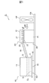
- FIG. 1 is a schematic side view of a phase change module 1 according to Embodiment 1 of a semiconductor element cooling device of the present invention.
- FIG. 2 is a schematic cross-sectional view of the phase change module 1 taken along the line II-II shown in FIG.
- FIG. 3 is a schematic front view of the phase change module 1 shown in FIG. 1 as viewed in the direction from the evaporator 10 to the condenser 20. 2 and 3, the circuit board CB and the like are not shown.
- the phase change module 1 includes, for example, a semiconductor element SD such as a central processing unit (CPU) mounted on a circuit board CB included in an electronic device such as a server, a storage device, and a network device. It is the semiconductor element cooling device using the thermosiphon cooled by.
- the phase change module 1 is connected to the evaporation unit 10 that vaporizes the liquid refrigerant R stored therein by the heat of the semiconductor element SD, and is condensed with the vapor of the refrigerant R introduced from the evaporation unit 10 to be liquid. And a condensing unit 20 for recirculating the refrigerant R to the evaporating unit 10.
- a semiconductor element SD such as a central processing unit (CPU) mounted on a circuit board CB included in an electronic device such as a server, a storage device, and a network device. It is the semiconductor element cooling device using the thermosiphon cooled by.
- the phase change module 1 is connected to the evaporation unit 10 that
- the evaporation unit 10 is a box-like airtight container provided with a bowl-shaped case 11 having a space inside and a vaporization promotion plate 12 thermally connected to the semiconductor element SD.
- the evaporation unit 10 is disposed so as to cover the upper surface of the semiconductor element SD, and, for example, a circuit board is formed by fastening a screw that is passed through a through hole provided in a peripheral part of the vaporization promoting plate 12 to a screw hole of the circuit board CB. It is fixed on CB.
- the case 11 and the vaporization promotion plate 12 can be manufactured using a metal material having excellent thermal conductivity, such as copper or aluminum.
- the case 11 and the vaporization promoting plate 12 are joined by an appropriate joining method such as pressure welding or brazing.
- a liquid refrigerant R is stored inside the evaporation unit 10.
- the case 11 is manufactured, for example, by deep drawing the above-described metal material.
- a connection portion 13 for connecting the evaporation portion 10 to the condensation portion 20 is opened on the side surface of the case 11.
- One end of a tubular connecting portion 30 is airtightly connected to the connecting portion 13. It is preferable that the height of the connection portion 13 is arranged at a position higher than the height position of the liquid level of the refrigerant R stored in the evaporation portion 10. Further, the case 11 may be provided with a hole for attaching the vaporization promotion plate 12.
- the vaporization promotion plate 12 is a plate-like member that is thermally connected to the surface of the semiconductor element SD.
- thermal conductive grease 14 is applied to the lower surface of the vaporization promoting plate 12.
- the vaporization promotion plate 12 is in close contact with the upper surface of the semiconductor element SD via the heat conductive grease 14.
- the upper surface of the vaporization promotion plate 12 is a boiling heat transfer surface 15 that transfers the heat of the semiconductor element SD to the refrigerant R stored in the evaporation unit 10.
- the boiling heat transfer surface 15 is provided along the horizontal direction, and has a predetermined area corresponding to the area of the upper surface of the semiconductor element SD, for example.
- the boiling heat transfer surface 15 has, for example, a porous structure having a large number of micropores.
- the boiling heat transfer surface 15 has minute irregularities formed by a large number of minute holes, and faces the inside of the evaporation unit 10 and holds the liquid refrigerant R in the number of minute holes.
- the porous structure of the boiling heat transfer surface 14 is provided, for example, in the central portion of the vaporization promotion plate 12 that overlaps the semiconductor element SD in the vertical direction. Note that the vaporization promoting plate 12 and the case 11 may be integrated to provide a similar porous structure on the inner surface of the case 11.
- the refrigerant R preferably has a surface tension smaller than that of water in the liquid state.
- a fluorocarbon refrigerant can be used. More specifically, for example, a refrigerant R having low surface tension and viscosity, high thermal and chemical stability, such as Novec (registered trademark) or Fluorinert (registered trademark) manufactured by Sumitomo 3M Limited, may be used. preferable.
- a refrigerant volume of 25 cc to 45 cc is appropriate in a CPU (semiconductor package) of about 100 W. This amount of refrigerant can secure a water level of about 1 cm to 2 cm from the boiling surface, and can more effectively reduce the possibility of liquid depletion in the heating element.
- the condensing unit 20 is a box-like airtight container provided with a bowl-shaped case 21 having a space inside and a condensation promoting plate 22 that promotes condensation of the vapor of the refrigerant R. Below the side surface of the case 21, a connection part 23 for connecting the condensing part 20 to the evaporation part 10 is provided below the side surface of the case 21, a connection part 23 for connecting the condensing part 20 to the evaporation part 10 is provided below the side surface of the case 21, a connection part 23 for connecting the condensing part 20 to the evaporation part 10 is provided below the side surface of the case 21, a connection part 23 for connecting the condensing part 20 to the evaporation part 10 is provided below the side surface of the case 21, a connection part 23 for connecting the condensing part 20 to the evaporation part 10 is provided below the side surface of the case 21, a connection part 23 for connecting the condensing part 20 to the evaporation part 10 is provided below the side surface of the case
- the condensing unit 20 is disposed at a position where it does not overlap with the evaporation unit 10 in the vertical direction and at least a portion thereof overlaps with the horizontal direction. In the present embodiment, the condensing unit 20 is disposed at a position where the entire condensing unit 20 overlaps the evaporation unit 10 in the horizontal direction. As shown in FIG. 2, the condensing unit 20 includes a steam introduction unit 24, a heat transfer unit 25, and a refrigerant recirculation unit 26.
- the vapor introduction part 24 is a part that introduces the vapor of the refrigerant R into the condensation part 20 along the horizontal direction.
- the surface of the condensation promotion plate 22 is flat, and the vapor of the refrigerant R introduced from the evaporation part 10 flows smoothly along the surface of the condensation promotion plate 22. Therefore, the vapor
- the heat transfer part 25 is a part adjacent to the steam introduction part 24 and from which the steam of the refrigerant R flows from the steam introduction part 24.
- a plurality of condensation fins 27 are erected on the surface of the condensation promotion plate 22 along the vertical direction.
- the condensing fins 27 extend from the vapor introducing portion 24 along a horizontal direction that intersects the direction in which the vapor of the refrigerant R is introduced.
- the refrigerant recirculation part 26 is a part provided on the opposite side of the steam introduction part 24 across the heat transfer part 25.
- a steam introduction part 24 is provided in the central part of the condensing part 20 along the direction of introduction of the vapor of the refrigerant R, and is transmitted to both sides in a direction intersecting the introduction direction of the vapor of the refrigerant R of the vapor introduction part 24.
- the heat part 25 is provided, and the refrigerant
- the refrigerant recirculation unit 26 recirculates the liquid refrigerant R condensed in the heat transfer unit 25 to the evaporation unit 10.
- an inclination, a groove, or the like that promotes the reflux of the liquid refrigerant R condensed in the heat transfer unit 25 to the evaporation unit 10 may be provided on the upper surface of the condensation promoting plate 22.
- an inclination may be provided so that the height position of the upper surface of the condensation promoting plate 22 becomes lower as it is closer to the evaporation unit 10 or the connection unit 23, and the reflux of the liquid refrigerant R to the evaporation unit 10 may be promoted.
- an inclined groove or recess may be provided in the connecting portion 23 so as to collect the liquid refrigerant R, and the reflux of the liquid refrigerant R to the evaporation section 10 may be promoted.
- the condensation fins 27 may be inclined at a predetermined angle with respect to the introduction direction of the vapor of the refrigerant R in the vapor introduction unit 24.
- the dimension in the width W2 direction of the condensing unit 20 is larger than the dimension in the depth D2 direction, and larger than the dimension in the width W1 direction of the evaporation unit 10 along the width W2 direction of the condensing unit 20.
- the horizontal direction along the introduction direction of the vapor of the refrigerant R in the vapor introduction unit 24 is defined as the depth D2 direction of the condensation unit 20, and the horizontal direction perpendicular to the depth D2 direction, that is, the introduction of the vapor of the refrigerant R in the vapor introduction unit 24.
- the direction intersecting the direction is the width W2 direction of the condensing unit 20.
- a tubular connecting portion 30 is connected to a connecting portion 23 provided on the lower side in the vertical direction at the center portion in the width W2 direction of the side surface of the condensing portion 20 facing the evaporation portion 10.
- the lower surface of the condensation promoting plate 22 of the condensing unit 20 is provided integrally with the condensing promoting plate 22 and thermally connected to the condensing unit 20.
- a cooling unit 40 for cooling the unit 25 and other parts is provided.
- the cooling unit 40 of the present embodiment is configured by a plurality of cooling fins 41 provided outside the condensing unit 20.
- the plurality of cooling fins 41 are formed in a thin plate shape along the depth D2 direction and the vertical direction of the condensing unit 20, and are arranged in parallel to each other with an interval in the width W2 direction of the condensing unit 20.
- a cooling fan CF is disposed on the side of the cooling unit 40. The cooling fan CF blows air between the cooling fins 41 along the depth D ⁇ b> 2 direction of the condensing unit 20 to promote heat dissipation of the cooling fins 41.
- the phase change module 1 of the present embodiment includes a tubular connecting part 30 that connects the evaporation part 10 and the condensing part 20.
- One end of the connecting portion 30 is connected to the connecting portion 13 provided at a position higher than the liquid level of the refrigerant R on the side surface of the evaporation portion 10, and the other end is connected to the bottom surface of the condensing portion 20, that is, the upper surface of the condensation promoting plate 22. It connects with the connection part 23 of the condensation part 20 provided in the height position.
- at least a part of the opening at the end of the connecting part 30 connected to the connecting part 23 on the side surface of the condensing part 20 and the upper surface of the condensation promoting plate 22 adjacent to the opening are located at the same height position. Yes.
- the height position of the connecting part 30 is gradually increased from the evaporation part 10 toward the condensing part 20. That is, the height position of the connecting part 30 is the lowest at the connection part 13 of the evaporation part 10 and is the highest at the connection part 23 of the condensing part 20.
- the connecting part 30 is a straight pipe parallel to the depth D2 direction of the condensing part 20, that is, the extending direction of the steam introducing part 24 in plan view.
- the shape of the connection part 30 will not be specifically limited if it is a shape which can introduce
- the connecting part 30 may be curved in the middle like an L-shaped tube, an S-shaped tube, or a flexible piping.
- the connecting unit 30 recirculates the liquid refrigerant R from the condensing unit 10 to the evaporating unit 20 at the same time as supplying the vapor of the refrigerant R from the evaporating unit 10 to the condensing unit 20. That is, the connecting portion 30 causes the gas-phase refrigerant R and the liquid-phase refrigerant R to simultaneously flow in opposite directions. Therefore, the inner diameter of the connecting portion R is, for example, in the range where the heat generation amount of the semiconductor element SD to be cooled is 100 W class and the volume of the liquid refrigerant R stored in the evaporation portion 10 is about 25 cc to about 45 cc. In some cases, for example, a range from about 15 mm to about 25 mm is preferred.
- phase change module 1 of the present embodiment will be described.
- the cooling performance of the semiconductor element SD is emphasized, and the height dimension in the vertical direction is not considered as a problem.
- the part for evaporating the refrigerant R and the part for condensing the vapor of the refrigerant R are arranged at positions overlapping each other in the vertical direction, and the vertical dimension is relatively large. Was satisfied with the cooling performance.
- the evaporator 10 and the condenser 20 are arranged at positions that do not overlap in the vertical direction and at least partially overlap in the horizontal direction.
- the height dimension of the perpendicular direction of the phase change module 1 can be reduced compared with the past.
- the whole condensation part 20 is arrange
- phase change of the refrigerant R is used as described below while reducing the vertical height dimension of the phase change module 1 as described above.
- the semiconductor element SD can be efficiently cooled.
- the evaporation unit 10 of the phase change module 1 is thermally connected to the semiconductor element SD via the vaporization promotion plate 12 disposed on the upper surface of the semiconductor element SD on the circuit board CB. Therefore, heat generated during the operation of the semiconductor element SD is transmitted to the vaporization promotion plate 12.
- the vaporization promoting plate 12 is in close contact with the upper surface of the semiconductor element SD via the heat conductive grease 14. As a result, good thermal bonding between the vaporization promoting plate 12 and the semiconductor element SD is ensured, and the heat of the semiconductor element SD is efficiently transferred to the vaporization promoting plate 12.
- the temperature of the boiling heat transfer surface 15 holding the liquid refrigerant R stored in the evaporation unit 10 rises, and the liquid refrigerant R boils. Heated by the heat transfer surface 15.
- the boiling heat transfer surface 15 is a surface that extends in the horizontal direction, and has a porous structure including a large number of micropores. Therefore, when the amount of heat transferred to the boiling heat transfer surface 15 is small, the liquid refrigerant R impregnates the boiling heat transfer surface 15 to fill the micropores.
- the evaporation of the liquid refrigerant R in the micropores is promoted by lowering the water level. Therefore, the heat dissipation performance of the vaporization promotion plate 12 is improved and the heat transport amount is increased. That is, since the boiling heat transfer surface 15 of the vaporization promotion plate 12 has a porous structure, evaporation is promoted by a temperature rise accompanying an increase in the amount of heat transferred. In addition, the evaporation of the liquid refrigerant R is further promoted by the increase in the vapor amount of the refrigerant R in the evaporation unit 10. Therefore, the greater the amount of heat transmitted to the vaporization promoting plate 12, the greater the amount of heat transported and the greater the efficiency. Therefore, the vaporization promotion plate 12 exhibits stable evaporation performance (vaporization performance) unless the liquid refrigerant R is depleted.
- the liquid refrigerant in the evaporation unit 10 is provided at a position where the height of the connection unit 13 is higher than the height of the liquid level of the liquid refrigerant R stored in the evaporation unit 10. R is prevented from flowing into the connecting portion 30.
- the vapor of the refrigerant R that has flowed into the connecting part 30 reaches the connecting part 23 on the side surface of the case 21 of the condensing part 20 through the connecting part 30 and is introduced into the steam introducing part 24 of the condensing part 20.
- the upper surface of the condensation promoting plate 22 is a flat surface along the horizontal direction, and has no obstacle in the depth D2 direction of the condensation part 20 for introducing the vapor of the refrigerant R.
- transduced into the position of the near side of the depth direction D2 of the condensation part 20 near the evaporation part 10 is made into the depth side of the depth direction D2 of the condensation part 20 far from the evaporation part 10 by the vapor
- the steam of the refrigerant R introduced into the steam introduction part 24 is guided to the heat transfer part 25 by a plurality of condensation fins 27 extending in a direction crossing the introduced direction in the process of flowing in the depth D2 direction of the condensation part 20.
- the plurality of condensing fins 27 are arranged adjacent to the vapor introducing portion 24 at intervals in the direction of introducing the vapor of the refrigerant R, that is, the depth D2 direction of the condensing portion 20.
- a cooling unit 40 composed of a plurality of cooling fins 41 is provided on the lower surface of the condensation promoting plate 22 of the condensing unit 20, and a cooling fan CF is disposed on the side of the cooling unit 40. Accordingly, air is caused to flow between the plurality of cooling fins 41 by the blowing of the cooling fan CF, the heat of the cooling fins 41 is efficiently radiated into the air, and the heat transfer unit 25 and other parts of the condensing unit 20 are efficiently released. Can be cooled.
- the dimension in the width W2 direction of the condensing part 20 is larger than the dimension in the depth D2 direction, and larger than the dimension W1 of the evaporation part 10 along the width W2 direction of the condensing part 20.
- the heat transfer of the condensation unit 20 If the temperature difference between the boiling heat transfer surface 15 in the evaporation unit 10 and the vapor of the refrigerant R is equal to the temperature difference between the heat transfer unit 25 in the condensation unit 20 and the vapor of the refrigerant R, the heat transfer of the condensation unit 20.
- the area needs to be about three times the heat transfer area of the boiling heat transfer surface 15. Even in such a case, it is possible to secure the heat radiation area of the heat transfer section 25 by making the dimension of the condensing unit 20 in the width W2 direction larger than the dimension W1 of the evaporation unit 10 in the width W2 direction.
- the steam introduced from the steam introducing unit 24 to the heat transfer unit 25 is transferred from the steam introducing unit 24 having a relatively high temperature. It can be introduced and cooled to a remote location where the temperature is relatively low. Therefore, the cooling performance of the condensing part 20 can be improved.
- the vapor of the refrigerant R introduced into the heat transfer section 25 of the condensation section 20 is cooled and condensed by heat exchange with the condensation fins 27 and the condensation promotion plate 22 in the heat transfer section 25 and returns to the liquid refrigerant R.
- the refrigerant recirculation part 26 is provided further downstream of the heat transfer part 25 on the downstream side of the vapor of the refrigerant R introduced into the vapor introduction part 24. Therefore, the liquid refrigerant R condensed in the heat transfer section 25 flows into the refrigerant recirculation section 26 on the downstream side.
- the liquid refrigerant R further flows through the refrigerant recirculation part 26 along the inner surface of the case 21, and gathers from the back side position of the condensing part 20 far from the evaporation part 10 to the near side position near the evaporation part 10. It flows out from the connection part 23 opened to the side surface of 21.
- the connecting part 30 that connects the evaporation part 10 and the condensing part 20 has one end connected to the connecting part 13 of the evaporation part 10 and the other end provided at the height position of the upper surface of the condensation promoting plate 22.
- the connection part 23 is connected. Therefore, the liquid refrigerant R collected by the refrigerant recirculation part 26 easily flows into the opening of the connection part 30 from the upper surface of the condensation promoting plate 22.
- the condensing promoting plate 22 of the condensing unit 20 since the upper surface of the condensation promoting plate 22 of the condensing unit 20 is disposed at a position higher than the liquid level of the refrigerant R in the evaporation unit 10, the condensing promoting plate 22 flows into the opening of the connecting unit 30 from the upper surface of the condensation promoting plate 22.
- the liquid refrigerant R is refluxed from the condensation unit 20 to the evaporation unit 10 by gravity.
- the flow of the liquid refrigerant R from the condensing unit 20 to the evaporating unit 10 is It is prevented that the refrigerant R is blocked by the flow of the refrigerant R to the condensing unit 20.
- the liquid refrigerant R can easily spread along the inner peripheral surface of the connecting portion 30.
- the connection part 30 it can prevent that the liquid refrigerant
- coolant R condensed between the condensation fins 27 provided in the heat-transfer part 25 of the condensation part 20 remains, and the cooling performance of the vapor
- connection part 30 is a straight pipe
- phase change module 1 of the present embodiment while the height dimension is reduced, the phase change for evaporating the liquid refrigerant R and the phase change for condensing the vapor of the refrigerant R are smoothly performed.
- the gas-phase and liquid-phase refrigerant R can be smoothly transferred and the cooling performance of the semiconductor element SD can be improved.
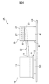
- FIG. 4 is a schematic side view of the phase change module 1A according to Embodiment 2 of the cooling device of the present invention.
- the connection part 23 of the condensing part 20 is provided on the condensation promoting plate 22, the end of the connecting part 30 is curved in front of the connecting part 23, and the connecting part 30 is the condensation promoting plate 22.
- This is different from the phase change module 1 of the first embodiment in that it is open on the upper surface of the condenser, that is, the bottom surface of the condensing unit 20. Since the other points of the phase change module 1A of the present embodiment are the same as those of the phase change module 1 of the first embodiment, the same portions are denoted by the same reference numerals and description thereof is omitted.
- phase change module 1A of the present embodiment since the connecting portion 30 is open on the upper surface of the condensation promoting plate 22, the liquid refrigerant R on the upper surface of the condensation promoting plate 22 easily flows into the connecting portion 30.
- an inclined surface or a concave portion is provided on the upper surface of the condensation promoting plate 22 so that the height position of the opening of the connecting portion 30 is lowered, so that the liquid refrigerant R on the upper surface of the condensation promoting plate 22 easily flows into the connecting portion 30. You may do it. Since the liquid refrigerant R easily flows into the connecting portion 30, it is prevented from accumulating on the upper surface of the condensation promoting plate 22, and the cooling performance of the refrigerant R in the condensing portion 20 is improved. Therefore, according to the phase change module 1A of the present embodiment, the same effect as the phase change module 1 of the first embodiment can be obtained, and the cooling performance of the semiconductor element SD can be improved.
- Embodiment 3 of the semiconductor element cooling device of the present invention will be described with reference to FIG.
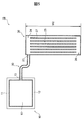
- FIG. 5 is a schematic cross-sectional view of a phase change module 1B according to Embodiment 3 of the cooling device of the present invention.
- the connecting part 30 is curved and connected to one end of the condensing part 20 in the width W2 direction, and the steam introducing part 24 of the condensing part 20 is provided at one end of the condensing part 20 in the width W2 direction.
- This is different from the phase change module 1 of the first embodiment. Since the other points of the phase change module 1B of the present embodiment are the same as those of the phase change module 1 of the first embodiment, the same parts are denoted by the same reference numerals and description thereof is omitted.
- the connecting part 30 is curved and connected to one end of the condensing part 20 in the width W2 direction. Therefore, according to the phase change module 1B of the present embodiment, not only the same effects as those of the phase change module 1 of the first embodiment can be obtained, but also the semiconductor element SD, the cooling fan CF, etc. on the circuit board CB of the electronic device. It is possible to arrange the positions of the evaporation unit 10 and the condensation unit 20 at positions different from those of the phase change module 1 of the first embodiment according to the layout of the components.
- Embodiment 4 of the semiconductor element cooling device of the present invention will be described with reference to FIG.
- FIG. 6 is a schematic side view of a phase change module 1C according to Embodiment 4 of the present invention.
- the cooling unit 40 provided on the lower surface of the condensation promoting plate 22 of the condensing unit 20 is configured by a water cooling unit 50 that is thermally connected to the condensing unit 20. This is different from the phase change module 1 of the first embodiment. Since the other points of the phase change module 1C of the present embodiment are the same as those of the phase change module 1 of the first embodiment, the same parts are denoted by the same reference numerals and description thereof is omitted.
- the water cooling unit 50 provided in the phase change module 1C of the present embodiment is connected to the water cooling jacket 51 that is provided on the lower surface of the condensation promoting plate 22 of the condensing unit 20 to cool the condensation promoting plate 22, and the water cooling jacket 51 and the pipe 52.
- a radiator 53, and a pump 56 that is connected to the radiator 53 and the water cooling jacket 51 by pipes 54 and 55 and circulates the coolant in the system of the water cooling section 50.
- the cooling liquid sent out by the pump 56 flows into the water cooling jacket 51 and cools the lower surface of the condensation promoting plate 22 of the condensing unit 20.
- the coolant whose temperature rises in the water cooling jacket 51 is discharged from the water cooling jacket 51 and flows into the radiator 53, and is cooled by releasing heat into the air blown by the air fan 53F.
- the coolant whose temperature has decreased in the radiator 53 is discharged from the radiator 53, flows into the pump 56, and is sent out by the pump 56 again.
- phase change module 1C of the present embodiment by cooling the condensing unit 20 by the water cooling unit 50, the cooling performance of the vapor of the refrigerant R in the condensing unit 20 is improved, and the cooling performance of the semiconductor element SD is improved. Can do.
- the radiator 53 and the pump 56 are connected to the housing of the electronic device. It may be arranged outside the body and shared among a plurality of electronic devices. Thereby, the increase in the height dimension of the electronic device due to the installation of the radiator 53 and the pump 56 can be prevented.
- Embodiment 5 of the semiconductor element cooling apparatus of the present invention will be described with reference to FIGS. 7 and 8 with reference to FIGS.
- FIG. 7 is a schematic side view of a phase change module 1D according to Embodiment 5 of the present invention.
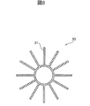
- 8 is a cross-sectional view taken along line VIII-VIII shown in FIG.
- the phase change module 1D of the present embodiment is different from the phase change module 1 of the first embodiment in that a plurality of cooling fins 31 are provided on the outer peripheral surface of the connecting portion 30. Since the other points of the phase change module 1D of the present embodiment are the same as those of the phase change module 1 of the first embodiment, the same parts are denoted by the same reference numerals and description thereof is omitted.
- the connecting portion 30 of the phase change module 1D of the present embodiment includes a plurality of thin cooling fins 31 extending along the longitudinal direction on the outer peripheral surface.
- the cooling fins 31 are provided radially in the radial direction in the cross-sectional view of the connecting portion 30.
- the heat radiation area of the connection part 30 increases, the temperature of the connection part 30 decreases, the gas-phase and liquid-phase refrigerant R flowing in the connection part 30 is cooled, and the cooling performance of the semiconductor element SD in the evaporation part 10 And the cooling performance of the vapor
- the cooling fins 31 do not necessarily have to be provided radially, and may be arranged in a flat plate shape along the horizontal direction, for example. Thereby, the height dimension of the cooling fin 31 can be reduced.
- FIG. 9 is a schematic cross-sectional view of a phase change module 1E according to Embodiment 6 of the present invention.
- the phase change module 1E of the present embodiment is different from the phase change module 1 of the first embodiment in that the connection unit 30 is not provided and the evaporation unit 10 and the condensation unit 20 are directly connected. Since the other points of the phase change module 1E of the present embodiment are the same as those of the phase change module 1 of the first embodiment, the same parts are denoted by the same reference numerals and description thereof is omitted.
- phase change module 1E of the present embodiment not only the same effects as those of the phase change module 1 of the first embodiment can be obtained, but the phase change module 1 can be In addition to downsizing, it is possible to reduce costs by reducing the amount of material used.
- FIG. 10 is an external perspective view of the rack 200 in which the server 100 according to the embodiment of the present invention is stored.
- FIG. 11 is a perspective view schematically showing an example of a schematic configuration in the housing 101 of the server 100 shown in FIG.
- FIG. 12 is a plan view schematically showing a schematic configuration in the housing 101 of the server 100 shown in FIG.
- FIG. 13 is a plan view schematically showing a modification of the server 100 shown in FIG. 11 to 13 show a state in which the lid that covers the upper portion of the housing 101 of the server 100 is removed.
- a plurality of servers 100 which are examples of the electronic apparatus of the present invention, are stacked and accommodated in a rack 200 in the vertical direction.
- the rack 200 includes a rack main body 201 that accommodates a plurality of servers 100, a door 202 attached to the rack main body 201, and a rail portion 203 that supports the casing 101 of each server 100, and each server can be taken out. Is housed in.
- the rack 200 is a so-called 19-inch rack in which, for example, the horizontal interval between the screws of the device mounting posts is 19 inches, and the height of the housing 101 of each server 100 is, for example, within 1 U (44.45 mm). It is said to be high.
- a plurality of hard disk drives 102 which are large-capacity recording devices, are arranged side by side on the front surface 101f side inside the housing 101 of the server 100 in consideration of maintainability.
- the hard disk drive 102 is one of the heat sources that have a relatively high temperature inside the housing 101. Therefore, a plurality of cooling fans CF for cooling the hard disk drive 102 are provided adjacent to the hard disk drive 102. In the present embodiment, four cooling fans CF are adjacent to the three hard disk drives 102.
- a block 103 that houses a cooling fan CF and a LAN that is an interface of a power source and communication means is provided.
- the circuit board CB is arranged.
- the circuit board CB includes a semiconductor element SD such as a CPU and phase change modules 1 and 1B that are the semiconductor element cooling devices described in the first and third embodiments.
- the server 100 of the present embodiment a plurality of servers 100 with high-performance semiconductor elements SD mounted in the rack 200 can be stored at high density, and the processing speed can be greatly improved.
- the condensing units 20 and 20 of the phase change modules 1 and 1B are arranged adjacent to the cooling fan CF that cools the hard disk drive 102. Therefore, the hard disk drive 102 and the phase change modules 1 and 1B can share the cooling fan CF. Thereby, compared with the case where the cooling fan CF only for phase change modules 1 and 1B is newly installed, a structure can be simplified and cost can be reduced.
- phase change modules 1 and 1B as the semiconductor cooling device, the power of a pump or the like is not required because the refrigerant R is circulated, and the server 100 having excellent cooling performance of the semiconductor element SD and excellent energy saving is provided. It becomes possible to provide. Furthermore, the phase change modules 1 and 1B have a relatively high heat exchange efficiency and a relatively simple structure. Therefore, even in an electronic device such as the server 100 that requires high-density mounting, the phase change modules 1 and 1B can be arranged with a relatively high degree of freedom.
- a plurality of cooling fans CF are arranged for the condensing units 20 and 20 of the phase change modules 1 and 1B. More specifically, in the example shown in FIGS. 12 and 13, two cooling fans CF are arranged adjacent to each condenser 20. Thus, even if one of the two cooling fans CF adjacent to each condensing unit 20 stops, the condensing unit 20 can be cooled by the other cooling fan CF, and the redundancy of the phase change modules 1 and 1B Will improve.
- the end of the connecting portion 30 connected to the condensing unit 20 has a small area facing the condensing unit 20 among the two cooling fans CF adjacent to the condensing unit 20. It is preferable to connect with the position which opposes. Thereby, even if any one cooling fan CF stops, the influence with respect to the cooling performance of the condensation part 20 can be reduced.
- the three cooling fans CF are provided for the two condensing units 20 of the two phase change modules 1 and 1B, and 1.5 are provided for the single condensing unit 20.
- the cooling fans CF are adjacent to each other. Therefore, when the cooling fan CF with a large opposing area stops, the condensing unit 20 is cooled by the remaining 0.5 cooling fans CF. In this case, the heat radiation amount is reduced in the range of about 2/3 of the condensing unit 20.
- the cooling performance of the CPU must be maintained at a minimum level during that time.
- the refrigerant flows evenly throughout the entire device. Therefore, if the effective heat radiation area is reduced to 1/3, the cooling performance of the refrigerant is reduced correspondingly and the temperature of the CPU is directly increased. There is a risk of affecting.
- the server 100 of the present embodiment in the range where the condensing unit 20 is not cooled, the condensation of the vapor of the refrigerant R is inhibited, and the vapor of the refrigerant R concentrates in the remaining part. Since the vapor of the refrigerant R concentrated in a part of the condensing unit 20 has a high flow velocity, the vapor of the liquid refrigerant R in the condensing unit 20 is swept away, and the condensing performance in the heat transfer unit 25 of the condensing unit 20 is improved. Thereby, the cooling performance of the CPU by the phase change modules 1 and 1B can be maintained within an allowable range. Therefore, according to the server 100 of this embodiment, it is possible to improve redundancy with a smaller number of cooling fans CF.
- SYMBOLS 1, 1A-1E Phase change module (semiconductor element cooling device), 10 ... Evaporating part, 20 ... Condensing part, 24 ... Steam introduction part, 25 ... Heat transfer part, 26 ... Refrigerant reflux part, 27 ... Condensing fin, 30 DESCRIPTION OF SYMBOLS ... Connection part, 31 ... Cooling fin, 40 ... Cooling part, 41 ... Cooling fin, 50 ... Water cooling part, 100 ... Server (electronic device), D2 ... Depth of condensing part, R ... Refrigerant, SD ... Semiconductor element, W1 ... Dimension of evaporation part, W2 ... Width of condensation part
Landscapes
- Cooling Or The Like Of Semiconductors Or Solid State Devices (AREA)
Abstract
La présente invention concerne un dispositif de refroidissement d'élément à semi-conducteur (1) qui refroidit un élément à semi-conducteur (SD) selon le changement de phase d'un réfrigérant (R), le dispositif de refroidissement d'élément à semi-conducteur (1) étant pourvu d'un évaporateur (10) pour vaporiser un liquide réfrigérant, qui est stocké à l'intérieur dudit évaporateur, en chauffant l'élément à semi-conducteur, et d'un condenseur (20), qui est accouplé à l'évaporateur, le condenseur (20) condensant de la vapeur du réfrigérant introduite à partir de l'évaporateur et faisant en sorte que le réfrigérant liquide circule vers l'évaporateur. Le condenseur est agencé dans une position plus élevée que la surface de liquide du réfrigérant à l'intérieur de l'évaporateur et est agencé pour qu'au moins une partie chevauche l'évaporateur dans la direction horizontale à une position qui ne chevauche pas l'évaporateur dans la direction verticale. Par conséquent, la hauteur de direction verticale du dispositif de refroidissement d'élément à semi-conducteur peut être réduite, tandis que l'élément à semi-conducteur est refroidi de manière efficace en raison du procédé à changement de phase.
Priority Applications (1)
| Application Number | Priority Date | Filing Date | Title |
|---|---|---|---|
| PCT/JP2014/054612 WO2015128951A1 (fr) | 2014-02-26 | 2014-02-26 | Dispositif de refroidissement d'élément à semi-conducteur et appareil électronique |
Applications Claiming Priority (1)
| Application Number | Priority Date | Filing Date | Title |
|---|---|---|---|
| PCT/JP2014/054612 WO2015128951A1 (fr) | 2014-02-26 | 2014-02-26 | Dispositif de refroidissement d'élément à semi-conducteur et appareil électronique |
Publications (1)
| Publication Number | Publication Date |
|---|---|
| WO2015128951A1 true WO2015128951A1 (fr) | 2015-09-03 |
Family
ID=54008323
Family Applications (1)
| Application Number | Title | Priority Date | Filing Date |
|---|---|---|---|
| PCT/JP2014/054612 Ceased WO2015128951A1 (fr) | 2014-02-26 | 2014-02-26 | Dispositif de refroidissement d'élément à semi-conducteur et appareil électronique |
Country Status (1)
| Country | Link |
|---|---|
| WO (1) | WO2015128951A1 (fr) |
Cited By (3)
| Publication number | Priority date | Publication date | Assignee | Title |
|---|---|---|---|---|
| JP2019165191A (ja) * | 2018-03-20 | 2019-09-26 | 廣達電脳股▲ふん▼有限公司 | サーバにおける拡張ヒートシンク設計 |
| CN111580630A (zh) * | 2020-05-08 | 2020-08-25 | 枣庄科技职业学院 | 计算机外设 |
| DE112022001934T5 (de) | 2021-04-01 | 2024-03-14 | Mitsubishi Heavy Industries, Ltd. | Kühlungssystem |
Citations (3)
| Publication number | Priority date | Publication date | Assignee | Title |
|---|---|---|---|---|
| JP2009079854A (ja) * | 2007-09-27 | 2009-04-16 | Daikin Ind Ltd | 空気調和装置 |
| JP2010080507A (ja) * | 2008-09-24 | 2010-04-08 | Hitachi Ltd | 電子装置 |
| JP2012229909A (ja) * | 2011-04-25 | 2012-11-22 | Google Inc | 電子装置のための熱サイフォンシステム |
-
2014
- 2014-02-26 WO PCT/JP2014/054612 patent/WO2015128951A1/fr not_active Ceased
Patent Citations (3)
| Publication number | Priority date | Publication date | Assignee | Title |
|---|---|---|---|---|
| JP2009079854A (ja) * | 2007-09-27 | 2009-04-16 | Daikin Ind Ltd | 空気調和装置 |
| JP2010080507A (ja) * | 2008-09-24 | 2010-04-08 | Hitachi Ltd | 電子装置 |
| JP2012229909A (ja) * | 2011-04-25 | 2012-11-22 | Google Inc | 電子装置のための熱サイフォンシステム |
Cited By (5)
| Publication number | Priority date | Publication date | Assignee | Title |
|---|---|---|---|---|
| JP2019165191A (ja) * | 2018-03-20 | 2019-09-26 | 廣達電脳股▲ふん▼有限公司 | サーバにおける拡張ヒートシンク設計 |
| US10842054B2 (en) | 2018-03-20 | 2020-11-17 | Quanta Computer Inc. | Extended heat sink design in server |
| CN111580630A (zh) * | 2020-05-08 | 2020-08-25 | 枣庄科技职业学院 | 计算机外设 |
| DE112022001934T5 (de) | 2021-04-01 | 2024-03-14 | Mitsubishi Heavy Industries, Ltd. | Kühlungssystem |
| US12501581B2 (en) | 2021-04-01 | 2025-12-16 | Mitsubishi Heavy Industries, Ltd. | Cooling system |
Similar Documents
| Publication | Publication Date | Title |
|---|---|---|
| US11116106B2 (en) | Cooling device, cooling system, and method of cooling | |
| JP6015675B2 (ja) | 冷却装置及びそれを用いた電子機器 | |
| JP5210997B2 (ja) | 冷却システム、及び、それを用いる電子装置 | |
| US7936560B2 (en) | Cooling device and electronic equipment including cooling device | |
| US7958935B2 (en) | Low-profile thermosyphon-based cooling system for computers and other electronic devices | |
| CN103931279B (zh) | 冷却机架式服务器的冷却装置和具备该冷却装置的数据中心 | |
| US8130497B2 (en) | Blade server | |
| CN101779395B (zh) | 电子系统、自由空间模块及其制造方法 | |
| US20050217829A1 (en) | Low-profile thermosyphon-based cooling system for computers and other electronic devices | |
| US20070258213A1 (en) | Apparatuses for dissipating heat from semiconductor devices | |
| KR20160139094A (ko) | 히트파이프를 구비한 전력전자 기기용 밀폐형 외함 | |
| CN105940279A (zh) | 冷却装置和具有它的数据中心 | |
| CN103717037A (zh) | 冷却系统以及使用了该冷却系统的电子装置 | |
| US6608751B2 (en) | Electronic device | |
| US20100032141A1 (en) | cooling system utilizing carbon nanotubes for cooling of electrical systems | |
| CN101416373B (zh) | 电力变换装置 | |
| US20150103486A1 (en) | Phase Change Module and Electronic Device Mounted with Same | |
| JP5874935B2 (ja) | 平板型冷却装置及びその使用方法 | |
| JP2010079401A (ja) | 冷却システム及びそれを用いた電子機器 | |
| JP2010080507A (ja) | 電子装置 | |
| JP2018133529A (ja) | 冷却装置 | |
| JPWO2007116461A1 (ja) | 冷却器 | |
| WO2016104727A1 (fr) | Dispositif de refroidissement | |
| JP5860728B2 (ja) | 電子機器の冷却システム | |
| WO2017208461A1 (fr) | Dispositif de refroidissement par ébullition et dispositif électronique sur lequel ledit dispositif de refroidissement par ébullition est monté |
Legal Events
| Date | Code | Title | Description |
|---|---|---|---|
| 121 | Ep: the epo has been informed by wipo that ep was designated in this application |
Ref document number: 14883569 Country of ref document: EP Kind code of ref document: A1 |
|
| NENP | Non-entry into the national phase |
Ref country code: DE |
|
| 122 | Ep: pct application non-entry in european phase |
Ref document number: 14883569 Country of ref document: EP Kind code of ref document: A1 |
|
| NENP | Non-entry into the national phase |
Ref country code: JP |