WO2015128985A1 - Dispositif d'affichage, procédé de commande, programme et support d'informations - Google Patents
Dispositif d'affichage, procédé de commande, programme et support d'informations Download PDFInfo
- Publication number
- WO2015128985A1 WO2015128985A1 PCT/JP2014/054857 JP2014054857W WO2015128985A1 WO 2015128985 A1 WO2015128985 A1 WO 2015128985A1 JP 2014054857 W JP2014054857 W JP 2014054857W WO 2015128985 A1 WO2015128985 A1 WO 2015128985A1
- Authority
- WO
- WIPO (PCT)
- Prior art keywords
- smoothness
- display
- vehicle
- road surface
- information
- Prior art date
- Legal status (The legal status is an assumption and is not a legal conclusion. Google has not performed a legal analysis and makes no representation as to the accuracy of the status listed.)
- Ceased
Links
Images





Classifications
-
- G—PHYSICS
- G06—COMPUTING OR CALCULATING; COUNTING
- G06T—IMAGE DATA PROCESSING OR GENERATION, IN GENERAL
- G06T3/00—Geometric image transformations in the plane of the image
- G06T3/40—Scaling of whole images or parts thereof, e.g. expanding or contracting
-
- G—PHYSICS
- G09—EDUCATION; CRYPTOGRAPHY; DISPLAY; ADVERTISING; SEALS
- G09G—ARRANGEMENTS OR CIRCUITS FOR CONTROL OF INDICATING DEVICES USING STATIC MEANS TO PRESENT VARIABLE INFORMATION
- G09G3/00—Control arrangements or circuits, of interest only in connection with visual indicators other than cathode-ray tubes
- G09G3/001—Control arrangements or circuits, of interest only in connection with visual indicators other than cathode-ray tubes using specific devices not provided for in groups G09G3/02 - G09G3/36, e.g. using an intermediate record carrier such as a film slide; Projection systems; Display of non-alphanumerical information, solely or in combination with alphanumerical information, e.g. digital display on projected diapositive as background
-
- B—PERFORMING OPERATIONS; TRANSPORTING
- B60—VEHICLES IN GENERAL
- B60K—ARRANGEMENT OR MOUNTING OF PROPULSION UNITS OR OF TRANSMISSIONS IN VEHICLES; ARRANGEMENT OR MOUNTING OF PLURAL DIVERSE PRIME-MOVERS IN VEHICLES; AUXILIARY DRIVES FOR VEHICLES; INSTRUMENTATION OR DASHBOARDS FOR VEHICLES; ARRANGEMENTS IN CONNECTION WITH COOLING, AIR INTAKE, GAS EXHAUST OR FUEL SUPPLY OF PROPULSION UNITS IN VEHICLES
- B60K35/00—Instruments specially adapted for vehicles; Arrangement of instruments in or on vehicles
- B60K35/20—Output arrangements, i.e. from vehicle to user, associated with vehicle functions or specially adapted therefor
- B60K35/21—Output arrangements, i.e. from vehicle to user, associated with vehicle functions or specially adapted therefor using visual output, e.g. blinking lights or matrix displays
- B60K35/22—Display screens
-
- B—PERFORMING OPERATIONS; TRANSPORTING
- B60—VEHICLES IN GENERAL
- B60K—ARRANGEMENT OR MOUNTING OF PROPULSION UNITS OR OF TRANSMISSIONS IN VEHICLES; ARRANGEMENT OR MOUNTING OF PLURAL DIVERSE PRIME-MOVERS IN VEHICLES; AUXILIARY DRIVES FOR VEHICLES; INSTRUMENTATION OR DASHBOARDS FOR VEHICLES; ARRANGEMENTS IN CONNECTION WITH COOLING, AIR INTAKE, GAS EXHAUST OR FUEL SUPPLY OF PROPULSION UNITS IN VEHICLES
- B60K35/00—Instruments specially adapted for vehicles; Arrangement of instruments in or on vehicles
- B60K35/20—Output arrangements, i.e. from vehicle to user, associated with vehicle functions or specially adapted therefor
- B60K35/28—Output arrangements, i.e. from vehicle to user, associated with vehicle functions or specially adapted therefor characterised by the type of the output information, e.g. video entertainment or vehicle dynamics information; characterised by the purpose of the output information, e.g. for attracting the attention of the driver
-
- B—PERFORMING OPERATIONS; TRANSPORTING
- B60—VEHICLES IN GENERAL
- B60K—ARRANGEMENT OR MOUNTING OF PROPULSION UNITS OR OF TRANSMISSIONS IN VEHICLES; ARRANGEMENT OR MOUNTING OF PLURAL DIVERSE PRIME-MOVERS IN VEHICLES; AUXILIARY DRIVES FOR VEHICLES; INSTRUMENTATION OR DASHBOARDS FOR VEHICLES; ARRANGEMENTS IN CONNECTION WITH COOLING, AIR INTAKE, GAS EXHAUST OR FUEL SUPPLY OF PROPULSION UNITS IN VEHICLES
- B60K35/00—Instruments specially adapted for vehicles; Arrangement of instruments in or on vehicles
- B60K35/20—Output arrangements, i.e. from vehicle to user, associated with vehicle functions or specially adapted therefor
- B60K35/29—Instruments characterised by the way in which information is handled, e.g. showing information on plural displays or prioritising information according to driving conditions
-
- B—PERFORMING OPERATIONS; TRANSPORTING
- B60—VEHICLES IN GENERAL
- B60W—CONJOINT CONTROL OF VEHICLE SUB-UNITS OF DIFFERENT TYPE OR DIFFERENT FUNCTION; CONTROL SYSTEMS SPECIALLY ADAPTED FOR HYBRID VEHICLES; ROAD VEHICLE DRIVE CONTROL SYSTEMS FOR PURPOSES NOT RELATED TO THE CONTROL OF A PARTICULAR SUB-UNIT
- B60W50/00—Details of control systems for road vehicle drive control not related to the control of a particular sub-unit, e.g. process diagnostic or vehicle driver interfaces
- B60W50/08—Interaction between the driver and the control system
- B60W50/14—Means for informing the driver, warning the driver or prompting a driver intervention
-
- G—PHYSICS
- G02—OPTICS
- G02B—OPTICAL ELEMENTS, SYSTEMS OR APPARATUS
- G02B27/00—Optical systems or apparatus not provided for by any of the groups G02B1/00 - G02B26/00, G02B30/00
- G02B27/01—Head-up displays
-
- G—PHYSICS
- G02—OPTICS
- G02B—OPTICAL ELEMENTS, SYSTEMS OR APPARATUS
- G02B27/00—Optical systems or apparatus not provided for by any of the groups G02B1/00 - G02B26/00, G02B30/00
- G02B27/01—Head-up displays
- G02B27/0101—Head-up displays characterised by optical features
-
- G—PHYSICS
- G02—OPTICS
- G02B—OPTICAL ELEMENTS, SYSTEMS OR APPARATUS
- G02B27/00—Optical systems or apparatus not provided for by any of the groups G02B1/00 - G02B26/00, G02B30/00
- G02B27/01—Head-up displays
- G02B27/0149—Head-up displays characterised by mechanical features
-
- G—PHYSICS
- G02—OPTICS
- G02B—OPTICAL ELEMENTS, SYSTEMS OR APPARATUS
- G02B27/00—Optical systems or apparatus not provided for by any of the groups G02B1/00 - G02B26/00, G02B30/00
- G02B27/64—Imaging systems using optical elements for stabilisation of the lateral and angular position of the image
- G02B27/646—Imaging systems using optical elements for stabilisation of the lateral and angular position of the image compensating for small deviations, e.g. due to vibration or shake
-
- G—PHYSICS
- G09—EDUCATION; CRYPTOGRAPHY; DISPLAY; ADVERTISING; SEALS
- G09G—ARRANGEMENTS OR CIRCUITS FOR CONTROL OF INDICATING DEVICES USING STATIC MEANS TO PRESENT VARIABLE INFORMATION
- G09G5/00—Control arrangements or circuits for visual indicators common to cathode-ray tube indicators and other visual indicators
-
- B—PERFORMING OPERATIONS; TRANSPORTING
- B60—VEHICLES IN GENERAL
- B60K—ARRANGEMENT OR MOUNTING OF PROPULSION UNITS OR OF TRANSMISSIONS IN VEHICLES; ARRANGEMENT OR MOUNTING OF PLURAL DIVERSE PRIME-MOVERS IN VEHICLES; AUXILIARY DRIVES FOR VEHICLES; INSTRUMENTATION OR DASHBOARDS FOR VEHICLES; ARRANGEMENTS IN CONNECTION WITH COOLING, AIR INTAKE, GAS EXHAUST OR FUEL SUPPLY OF PROPULSION UNITS IN VEHICLES
- B60K2360/00—Indexing scheme associated with groups B60K35/00 or B60K37/00 relating to details of instruments or dashboards
- B60K2360/1523—Matrix displays
-
- B—PERFORMING OPERATIONS; TRANSPORTING
- B60—VEHICLES IN GENERAL
- B60K—ARRANGEMENT OR MOUNTING OF PROPULSION UNITS OR OF TRANSMISSIONS IN VEHICLES; ARRANGEMENT OR MOUNTING OF PLURAL DIVERSE PRIME-MOVERS IN VEHICLES; AUXILIARY DRIVES FOR VEHICLES; INSTRUMENTATION OR DASHBOARDS FOR VEHICLES; ARRANGEMENTS IN CONNECTION WITH COOLING, AIR INTAKE, GAS EXHAUST OR FUEL SUPPLY OF PROPULSION UNITS IN VEHICLES
- B60K2360/00—Indexing scheme associated with groups B60K35/00 or B60K37/00 relating to details of instruments or dashboards
- B60K2360/16—Type of output information
- B60K2360/166—Navigation
-
- B—PERFORMING OPERATIONS; TRANSPORTING
- B60—VEHICLES IN GENERAL
- B60K—ARRANGEMENT OR MOUNTING OF PROPULSION UNITS OR OF TRANSMISSIONS IN VEHICLES; ARRANGEMENT OR MOUNTING OF PLURAL DIVERSE PRIME-MOVERS IN VEHICLES; AUXILIARY DRIVES FOR VEHICLES; INSTRUMENTATION OR DASHBOARDS FOR VEHICLES; ARRANGEMENTS IN CONNECTION WITH COOLING, AIR INTAKE, GAS EXHAUST OR FUEL SUPPLY OF PROPULSION UNITS IN VEHICLES
- B60K2360/00—Indexing scheme associated with groups B60K35/00 or B60K37/00 relating to details of instruments or dashboards
- B60K2360/16—Type of output information
- B60K2360/167—Vehicle dynamics information
-
- B—PERFORMING OPERATIONS; TRANSPORTING
- B60—VEHICLES IN GENERAL
- B60K—ARRANGEMENT OR MOUNTING OF PROPULSION UNITS OR OF TRANSMISSIONS IN VEHICLES; ARRANGEMENT OR MOUNTING OF PLURAL DIVERSE PRIME-MOVERS IN VEHICLES; AUXILIARY DRIVES FOR VEHICLES; INSTRUMENTATION OR DASHBOARDS FOR VEHICLES; ARRANGEMENTS IN CONNECTION WITH COOLING, AIR INTAKE, GAS EXHAUST OR FUEL SUPPLY OF PROPULSION UNITS IN VEHICLES
- B60K2360/00—Indexing scheme associated with groups B60K35/00 or B60K37/00 relating to details of instruments or dashboards
- B60K2360/18—Information management
- B60K2360/191—Highlight information
-
- B—PERFORMING OPERATIONS; TRANSPORTING
- B60—VEHICLES IN GENERAL
- B60W—CONJOINT CONTROL OF VEHICLE SUB-UNITS OF DIFFERENT TYPE OR DIFFERENT FUNCTION; CONTROL SYSTEMS SPECIALLY ADAPTED FOR HYBRID VEHICLES; ROAD VEHICLE DRIVE CONTROL SYSTEMS FOR PURPOSES NOT RELATED TO THE CONTROL OF A PARTICULAR SUB-UNIT
- B60W50/00—Details of control systems for road vehicle drive control not related to the control of a particular sub-unit, e.g. process diagnostic or vehicle driver interfaces
- B60W50/08—Interaction between the driver and the control system
- B60W50/14—Means for informing the driver, warning the driver or prompting a driver intervention
- B60W2050/146—Display means
-
- B—PERFORMING OPERATIONS; TRANSPORTING
- B60—VEHICLES IN GENERAL
- B60W—CONJOINT CONTROL OF VEHICLE SUB-UNITS OF DIFFERENT TYPE OR DIFFERENT FUNCTION; CONTROL SYSTEMS SPECIALLY ADAPTED FOR HYBRID VEHICLES; ROAD VEHICLE DRIVE CONTROL SYSTEMS FOR PURPOSES NOT RELATED TO THE CONTROL OF A PARTICULAR SUB-UNIT
- B60W2552/00—Input parameters relating to infrastructure
- B60W2552/35—Road bumpiness, e.g. potholes
-
- G—PHYSICS
- G02—OPTICS
- G02B—OPTICAL ELEMENTS, SYSTEMS OR APPARATUS
- G02B27/00—Optical systems or apparatus not provided for by any of the groups G02B1/00 - G02B26/00, G02B30/00
- G02B27/01—Head-up displays
- G02B27/0101—Head-up displays characterised by optical features
- G02B2027/014—Head-up displays characterised by optical features comprising information/image processing systems
-
- G—PHYSICS
- G02—OPTICS
- G02B—OPTICAL ELEMENTS, SYSTEMS OR APPARATUS
- G02B27/00—Optical systems or apparatus not provided for by any of the groups G02B1/00 - G02B26/00, G02B30/00
- G02B27/01—Head-up displays
- G02B27/0101—Head-up displays characterised by optical features
- G02B2027/0141—Head-up displays characterised by optical features characterised by the informative content of the display
-
- G—PHYSICS
- G09—EDUCATION; CRYPTOGRAPHY; DISPLAY; ADVERTISING; SEALS
- G09G—ARRANGEMENTS OR CIRCUITS FOR CONTROL OF INDICATING DEVICES USING STATIC MEANS TO PRESENT VARIABLE INFORMATION
- G09G2340/00—Aspects of display data processing
- G09G2340/04—Changes in size, position or resolution of an image
- G09G2340/0407—Resolution change, inclusive of the use of different resolutions for different screen areas
-
- G—PHYSICS
- G09—EDUCATION; CRYPTOGRAPHY; DISPLAY; ADVERTISING; SEALS
- G09G—ARRANGEMENTS OR CIRCUITS FOR CONTROL OF INDICATING DEVICES USING STATIC MEANS TO PRESENT VARIABLE INFORMATION
- G09G2340/00—Aspects of display data processing
- G09G2340/04—Changes in size, position or resolution of an image
- G09G2340/0464—Positioning
-
- G—PHYSICS
- G09—EDUCATION; CRYPTOGRAPHY; DISPLAY; ADVERTISING; SEALS
- G09G—ARRANGEMENTS OR CIRCUITS FOR CONTROL OF INDICATING DEVICES USING STATIC MEANS TO PRESENT VARIABLE INFORMATION
- G09G2340/00—Aspects of display data processing
- G09G2340/14—Solving problems related to the presentation of information to be displayed
-
- G—PHYSICS
- G09—EDUCATION; CRYPTOGRAPHY; DISPLAY; ADVERTISING; SEALS
- G09G—ARRANGEMENTS OR CIRCUITS FOR CONTROL OF INDICATING DEVICES USING STATIC MEANS TO PRESENT VARIABLE INFORMATION
- G09G2354/00—Aspects of interface with display user
-
- G—PHYSICS
- G09—EDUCATION; CRYPTOGRAPHY; DISPLAY; ADVERTISING; SEALS
- G09G—ARRANGEMENTS OR CIRCUITS FOR CONTROL OF INDICATING DEVICES USING STATIC MEANS TO PRESENT VARIABLE INFORMATION
- G09G2380/00—Specific applications
- G09G2380/10—Automotive applications
-
- G—PHYSICS
- G09—EDUCATION; CRYPTOGRAPHY; DISPLAY; ADVERTISING; SEALS
- G09G—ARRANGEMENTS OR CIRCUITS FOR CONTROL OF INDICATING DEVICES USING STATIC MEANS TO PRESENT VARIABLE INFORMATION
- G09G5/00—Control arrangements or circuits for visual indicators common to cathode-ray tube indicators and other visual indicators
- G09G5/22—Control arrangements or circuits for visual indicators common to cathode-ray tube indicators and other visual indicators characterised by the display of characters or indicia using display control signals derived from coded signals representing the characters or indicia, e.g. with a character-code memory
- G09G5/24—Generation of individual character patterns
- G09G5/26—Generation of individual character patterns for modifying the character dimensions, e.g. double width, double height
Definitions
- the present invention relates to a display technology that takes into account vehicle vibration.
- Patent Literature 1 includes a front camera that captures a landscape that enters the driver's line of sight in order to detect vehicle vibration, and a driver camera that captures changes in the relative position of the driver and the vehicle.
- a head-up display that improves visibility by changing the position of information projected on a combiner based on information acquired by a driver camera is disclosed.
- Patent Document 1 while deterioration of visibility due to vibration can be reduced, a front camera and a driver camera are required, so that there is a problem that the cost of system construction becomes expensive.
- the present invention has been made in order to solve the above-described problems, and has as its main object to provide a display device that can suitably suppress deterioration of visibility against vibration.
- the invention described in the claims is a display device, wherein the display control means displays characters or figures on the display means so as to overlap the scenery visually recognized from the vehicle, and the road surface on which the vehicle is traveling Road surface condition acquisition means for acquiring information relating to the smoothness of the road, wherein the display control means changes the size of the character or figure according to the information relating to the smoothness acquired by the road surface condition acquisition means It is characterized by making it.
- the invention described in claim is a control method executed by a display device, wherein a display control step of displaying characters or figures on a display means so as to overlap the scenery visually recognized from a vehicle, A road surface condition acquisition step of acquiring information on the smoothness of the road surface on which the vehicle is traveling, and the display control step is configured to select the character according to the information on the smoothness acquired in the road surface state acquisition step. Alternatively, the size of the figure is changed.
- the invention described in claim is a program executed by a computer, the display control means for displaying characters or figures on the display means so as to overlap the scenery visually recognized from the vehicle, and the vehicle
- the computer is caused to function as road surface condition acquisition means for acquiring information relating to smoothness of a road surface that is running, and the display control means is configured to use the character according to the information relating to the smoothness acquired by the road surface condition acquisition means. Alternatively, the size of the figure is changed.
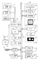
- 1 shows a schematic configuration of a display system.
- 1 shows a schematic configuration of a navigation device.
- 1 shows a schematic configuration of a head-up display.
- the schematic structure of a light source unit is shown.
- the graph which shows the relationship between the travel speed of a vehicle and the vibration amount of a vehicle is shown. It is the table
- It is a flowchart which shows the display process of the guidance image which concerns on 1st Example. A display example of the combiner is shown.
- the schematic structure of the display system which concerns on 2nd Example is shown. It is a graph which shows the relationship between the travel speed of the vehicle at the time of drive
- the display device includes display control means for displaying characters or figures on the display means so as to overlap the scenery visually recognized from the vehicle, and a road on which the vehicle is traveling.
- Road surface condition acquisition means for acquiring information on the smoothness of the surface
- the display control means determines the size of the character or figure according to the information on the smoothness acquired by the road surface condition acquisition means. Change.
- the display device includes display control means and road surface condition acquisition means.
- the display control means displays characters or figures on the display means so as to overlap the scenery visually recognized from the vehicle.
- the road surface condition acquisition means acquires information relating to the smoothness of the road surface on which the vehicle is traveling. Then, the display control means changes the size of the character or graphic displayed on the display means according to the information on the smoothness acquired by the road surface condition acquisition means. By doing in this way, the display apparatus can change the display size of the character and figure displayed on a display means according to the road surface condition of a road surface, and can make a driver
- the display control unit increases the size of the character or the figure as the smoothness of the road surface indicated by the information on the smoothness deteriorates. According to this aspect, even when the vehicle is traveling on a road surface with poor smoothness, the size of characters or figures to be displayed can be increased, and these can be suitably viewed by the driver.
- the display device includes a speed acquisition unit that acquires a traveling speed of the vehicle, and a vibration amount acquisition unit that acquires a magnitude of vibration of the vehicle.
- the means acquires information on the smoothness based on the travel speed and the vibration amount. According to this aspect, the display device can appropriately estimate the smoothness of the road surface.
- the road surface condition acquisition unit acquires information on the smoothness from map data in which information on the smoothness is recorded in advance in association with each road. Also according to this aspect, the display device can appropriately acquire information related to the smoothness of the road surface and appropriately determine the display size of characters and figures to be displayed.
- the display device includes speed acquisition means for acquiring the travel speed of the vehicle, and the display control means is estimated based on the information related to the smoothness and the travel speed. The size of the character or figure is changed according to the estimated vibration amount. According to this aspect, the display device can appropriately estimate the amount of vibration of the vehicle, and appropriately change the size of characters or figures to be displayed according to the estimated amount of vibration.
- the road surface condition acquisition unit acquires, as information about the smoothness, a vibration amount detected by a sensor that detects vibration of the vehicle, and the display control unit includes the road surface condition.
- the size of the character or figure is changed according to the amount of vibration acquired by the acquisition means.
- the display device can appropriately change the size of characters or figures to be displayed in accordance with the detected vibration amount.
- a display control process executed by the display device, the display control step of displaying characters or graphics on the display means so as to overlap the scenery visually recognized from the vehicle, Road surface condition acquisition step for acquiring information on the smoothness of the road surface on which the vehicle is traveling, and the display control step is performed according to the information on the smoothness acquired by the road surface state acquisition step, Change the size of a character or figure.
- the display device can change the display size of the characters and graphics displayed on the display means in accordance with the road surface condition of the road surface, so that the driver can visually recognize them appropriately.
- a program executed by a computer the display control means for displaying characters or figures on a display means so as to overlap the scenery visually recognized from the vehicle, and the vehicle
- the computer is caused to function as road surface condition acquisition means for acquiring information relating to smoothness of a road surface that is running, and the display control means is configured to use the character according to the information relating to the smoothness acquired by the road surface condition acquisition means. Or change the size of the figure.
- the computer can change the display size of characters and figures displayed on the display means in accordance with the road surface condition of the road surface, and allow the driver to visually recognize them appropriately.
- the program is stored in a storage medium.
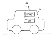
- FIG. 1 shows a configuration example of a display system 100 according to the embodiment.
- the display system 100 is mounted on a vehicle Ve and includes a navigation device 1, a head-up display 2, and a vibration sensor 3.
- the navigation device 1 has a function of performing route guidance from the departure point to the destination.
- the navigation device 1 can be a mobile phone such as a stationary navigation device installed in the vehicle Ve, a PND (Portable Navigation Device), or a smartphone.
- the head-up display 2 generates an image (also referred to as a “guidance image”) that displays map information including the current position, route guidance information, the traveling speed of the vehicle Ve, facility marks, and other guidance information that assists driving.
- This is a device that visually recognizes the guide image as a virtual image from the position (eye point) of the driver's eyes.
- the head-up display 2 adjusts the size of the guide image according to the road surface condition so that the driver can visually recognize the guide image even when the vehicle Ve vibrates.
- the vibration sensor 3 detects the amount of vibration of the vehicle Ve. Then, the vibration sensor 3 supplies a detection signal Sd indicating the detected vibration amount to the head-up display 2.
- the navigation device 1 may be held by a cradle or the like. In this case, the navigation device 1 may exchange information with the head-up display 2 via a cradle or the like. Further, the vibration sensor 3 may be connected to the navigation device 1 instead of the head-up display 2. In this case, the navigation device 1 transfers the detection signal Sd to the head-up display 2 when receiving the detection signal Sd from the vibration sensor 3.
- FIG. 2 shows the configuration of the navigation device 1.
- the navigation device 1 includes a self-supporting positioning device 10, a GPS receiver 18, a system controller 20, a disk drive 31, a data storage unit 36, a communication interface 37, a communication device 38, an interface 39, and a display unit 40.
- the self-supporting positioning device 10 includes an acceleration sensor 11, an angular velocity sensor 12, and a distance sensor 13.
- the acceleration sensor 11 is made of, for example, a piezoelectric element, detects the acceleration of the vehicle Ve, and outputs acceleration data.
- the angular velocity sensor 12 is composed of, for example, a vibrating gyroscope, detects the angular velocity of the vehicle Ve when the direction of the vehicle Ve is changed, and outputs angular velocity data and relative azimuth data.
- the distance sensor 13 measures a vehicle speed pulse composed of a pulse signal generated with the rotation of the wheel of the vehicle Ve.
- the GPS receiver 18 receives radio waves 19 carrying downlink data including positioning data from a plurality of GPS satellites.
- the positioning data is used to detect the absolute position (also referred to as “current position”) of the vehicle Ve from latitude and longitude information.
- the system controller 20 includes an interface 21, a CPU (Central Processing Unit) 22, a ROM (Read Only Memory) 23, and a RAM (Random Access Memory) 24, and controls the entire navigation device 1.
- a CPU Central Processing Unit
- ROM Read Only Memory
- RAM Random Access Memory
- the interface 21 performs an interface operation with the acceleration sensor 11, the angular velocity sensor 12, the distance sensor 13, and the GPS receiver 18. From these, vehicle speed pulses, acceleration data, relative azimuth data, angular velocity data, GPS positioning data, absolute azimuth data, and the like are input to the system controller 20.
- the CPU 22 controls the entire system controller 20.
- the ROM 23 includes a nonvolatile memory (not shown) in which a control program for controlling the system controller 20 is stored.
- the RAM 24 stores various data such as route data preset by the user via the input device 60 so as to be readable, and provides a working area to the CPU 22.
- a system controller 20 a disk drive 31 such as a CD-ROM drive or a DVD-ROM drive, a data storage unit 36, a communication interface 37, a display unit 40, an audio output unit 50 and an input device 60 are mutually connected via a bus line 30. It is connected to the.
- the disk drive 31 reads and outputs content data such as music data and video data from a disk 33 such as a CD or DVD under the control of the system controller 20.
- the disk drive 31 may be either a CD-ROM drive or a DVD-ROM drive, or may be a CD and DVD compatible drive.
- the data storage unit 36 is configured by, for example, an HDD or the like, and stores various data used for navigation processing such as map data.
- the map data includes road data represented by links corresponding to roads and nodes corresponding to road connecting portions, facility information about each facility, and the like.
- the communication device 38 is composed of, for example, an FM tuner, a beacon receiver, a portable terminal, a dedicated communication module, and the like, and via a communication interface 37, traffic jams distributed from a VICS (registered trademark, Vehicle Information Communication System) center Receive road traffic information such as traffic information and other information.
- VICS Vehicle Information Communication System
- the communication device 38 includes various information used for navigation processing such as guide route information, current position information acquired from the GPS receiver 18, information such as vehicle speed pulses acquired from the autonomous positioning device 10, and map data. It transmits to the up display 2.
- the display unit 40 displays various display data on a display device such as a display under the control of the system controller 20.
- the system controller 20 reads map data from the data storage unit 36.
- the display unit 40 displays the map data read from the data storage unit 36 by the system controller 20 on the display screen.
- the display unit 40 includes a graphic controller 41 that controls the entire display unit 40 based on control data sent from the CPU 22 via the bus line 30 and a memory such as a VRAM (Video RAM), and can display image information that can be displayed immediately.
- a buffer memory 42 that temporarily stores, a display control unit 43 that controls display of a display 44 such as a liquid crystal or a CRT (Cathode Ray Tube) based on image data output from the graphic controller 41, and a display 44 are provided.
- the display 44 functions as an image display unit, and includes, for example, a liquid crystal display device having a diagonal size of about 5 to 10 inches and is mounted near the front panel in the vehicle.
- the audio output unit 50 performs D / A (Digital to Analog) conversion of audio digital data sent from the CD-ROM drive 31, DVD-ROM 32, RAM 24, or the like via the bus line 30 under the control of the system controller 20.
- a D / A converter 51 to perform an amplifier (AMP) 52 that amplifies the audio analog signal output from the D / A converter 51, and a speaker 53 that converts the amplified audio analog signal into sound and outputs the sound into the vehicle. It is prepared for.
- AMP amplifier
- the input device 60 includes keys, switches, buttons, a remote controller, a voice input device, and the like for inputting various commands and data.
- the input device 60 is disposed around the front panel and the display 44 of the main body of the in-vehicle electronic system mounted in the vehicle.
- the display 44 is a touch panel system
- the touch panel provided on the display screen of the display 44 also functions as the input device 60.
- FIG. 3 is a schematic configuration diagram of the head-up display 2.
- the head-up display 2 includes a light source unit 4 and a combiner 9.
- the vehicle Ve includes a front window 25, a ceiling portion 27, a hood 28, a dashboard 29, and the like. It is attached.
- the light source unit 4 is installed on the ceiling portion 27 in the passenger compartment via the support members 5a and 5b, and emits light constituting a guide image indicating information for assisting driving toward the combiner 9 so that the combiner 9 The driver is caused to visually recognize the virtual image “Iv”.
- the combiner 9 projects the display image emitted from the light source unit 4 and reflects the display image to the driver's eye point “Pe” to display the display image as a virtual image Iv. And the combiner 9 has the support shaft part 8 installed in the ceiling part 27, and rotates the support shaft part 8 as a spindle.
- the support shaft portion 8 is installed, for example, in the vicinity of the ceiling portion 27 in the vicinity of the upper end of the front window 25, in other words, the position where a sun visor (not shown) for the driver is installed.
- the support shaft portion 8 may be installed instead of the above-described sun visor.
- the combiner 9 is an example of the “display unit” in the present invention.
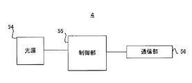
- FIG. 4 is a diagram schematically showing the configuration of the light source unit 4.
- the light source unit 3 includes a light source 54, a control unit 55, and a communication unit 56.
- the light source 54 includes, for example, red, blue, and green laser light sources, and emits light (also referred to as “display light”) that constitutes a display image to be irradiated to the combiner 9 based on the control of the control unit 55. .
- the communication unit 56 receives various information used for the navigation processing from the navigation device 1 based on the control of the control unit 55. For example, the communication unit 56 receives information necessary for generating a guidance image such as guidance route information, current position information, and vehicle speed information from the navigation device 1. In addition, the communication unit 56 receives the detection signal Sd from the vibration sensor 3.
- the control unit 55 includes a CPU, a ROM that stores a control program executed by the CPU, data, and the like, and a RAM that sequentially reads and writes various data as a work memory when the CPU operates. Control.
- the control unit 55 generates a guide image based on the information transmitted from the navigation device 1 and causes the light source 54 to emit display light constituting the guide image. Further, in the present embodiment, the control unit 55 is based on the travel speed information acquired from the navigation device 1 and the amount of vibration indicated by the detection signal Sd acquired from the vibration sensor 3 (simply the road on which the vehicle Ve is traveling) (simply Recognize the road surface condition of “traveling road”. And the control part 55 changes the display size of a guidance image according to the road surface condition of the recognized driving road. This is described in detail in the section “Adjusting the display size”.
- the control unit 55 functions as a “road surface condition acquisition unit”, “display control unit”, “speed acquisition unit”, “vibration amount acquisition unit” and a computer that executes a program in the present invention.
- the control unit 55 calculates an index (also referred to as “smoothness determination index ⁇ ”) indicating the smoothness degree of the traveling road based on the traveling speed of the vehicle Ve and the vibration amount indicated by the detection signal Sd.
- the display size of the guide image is changed stepwise according to the smoothness determination index ⁇ .
- the smoothness determination index ⁇ is an example of “information relating to smoothness” in the present invention, and in this embodiment, the smoother the road surface, the lower the value.
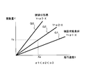
- FIG. 5 shows graphs G1 to G3 when the traveling speed of the vehicle Ve is the X axis and the vibration amount of the vehicle Ve is the Y axis.
- the graph G1 shows the relationship between the travel speed and the vibration amount when the smoothness determination index ⁇ is “ ⁇ 1”, that is, when the pavement state of the travel road is good.
- Graph G3 shows the relationship between the running speed and the vibration amount when the smoothness judgment index ⁇ is “ ⁇ 3”, that is, when the running road is poorly paved, and the graph G2 shows the smoothness judgment.
- the relationship between the traveling speed and the vibration amount when the index ⁇ is an intermediate value “ ⁇ 2” between “ ⁇ 1” and “ ⁇ 3” is shown.
- the control unit 55 can calculate the smoothness determination index ⁇ corresponding to the slope of the graph based on the traveling speed and the vibration amount.
- control unit 55 also includes a moving average in the time series of the traveling speed (also referred to as “speed average Xa”) and a moving average in the time series of the detected vibration amount (also referred to as “vibration average Ya”).
- speed average Xa a moving average in the time series of the traveling speed
- vibration average Ya a moving average in the time series of the detected vibration amount
- the control unit 55 calculates the smoothness determination index ⁇ 2 using the speed average Xa and the vibration average Ya.
- the control unit 55 calculates the speed average Xa based on the information on the traveling speed for a predetermined number immediately before acquired from the navigation device 1, and the vibration average Ya for the predetermined number immediately before acquired from the vibration sensor 3. Is calculated based on the detection signal Sd.
- the predetermined number described above is set to a conforming value based on, for example, experiments. In this way, by calculating the smoothness determination index ⁇ using the travel speed and the vibration amount obtained by moving average, the control unit 55 suitably removes sudden noise components.
- the control unit 55 recognizes the level to which the calculated smoothness determination index ⁇ belongs (also referred to as “determination level Lv”), and determines the display size of the guidance image according to the determination level Lv.
- determination level Lv has four levels of level 1 to level 4, and is higher as the smoothness determination index ⁇ is larger.
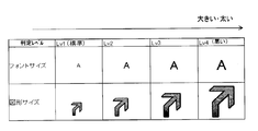
- FIG. 6 is a table visually showing the relationship between the determination level Lv and the font size and figure size of the guide image.
- the control unit 55 increases the font size of the character indicated by the guide image and the size of the graphic indicated by the guide image as the determination level Lv is higher.
- the control unit 55 stores in advance a digitized table showing the relationship between the determination level Lv and the font size and graphic size of the guide image as shown in FIG. That is, the control unit 55 stores in advance numerical values indicating the font size and graphic size of the guide image corresponding to each determination level Lv.
- the control unit 55 determines that the guide image is difficult to see due to the vibration of the vehicle Ve on the road on which the determination level Lv is high and the pavement state is determined to be bad.
- the displayed characters and figures are displayed large. Thereby, the control part 55 raises the visibility of a guidance image and makes a driver
- the control unit 55 determines that the guide image is easily visible on the road on which the determination level Lv is low and the smoothness is determined to be high, and displays the guide image in a standard size. Thereby, the control part 55 can prevent the visibility from deteriorating due to the guide image being unnecessarily large, and can suitably ensure the visibility of the driver in front of the scenery.
- control unit 55 gives hysteresis to the threshold value of the smoothness determination index ⁇ for determining the determination level Lv in order to prevent the guide image size setting from changing frequently. This will be described with reference to FIG.
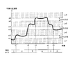
- FIG. 7 is a graph showing temporal changes in the smoothness determination index ⁇ and the determination level Lv of the traveling road when the vehicle Ve travels for a predetermined period.
- the control unit 55 lowers the level of the smoothness determination index ⁇ ( ⁇ 2, ⁇ 4, ⁇ 6) that is one level lower than the threshold level ( ⁇ 2, ⁇ 4, ⁇ 6) for determining whether or not to increase to each level of the determination level Lv.
- the thresholds ( ⁇ 1, ⁇ 3, ⁇ 5) of the smoothness determination index ⁇ for determining whether or not to decrease are set low.
- the former threshold value is referred to as “carry-up threshold value” and the latter threshold value is also referred to as “carry-down threshold value”.
- control unit 55 sets the advance threshold value for the determination level Lv to increase from the level 1 to the level 2 as “ ⁇ 2”, and the decrease threshold value for the determination level Lv to decrease from the level 2 to the level 1 as lower than ⁇ 2. ⁇ 1 ”.
- control unit 55 sets “ ⁇ 4” as the carry threshold for raising the determination level Lv from level 2 to level 3 and “ ⁇ 3”, which is lower than the push-down threshold for reducing the decision level Lv from level 3 to level 2.
- the carry threshold for raising the determination level Lv from level 3 to level 4 is “ ⁇ 6”
- the carry threshold for lowering the determination level Lv from level 4 to level 3 is “ ⁇ 5” lower than ⁇ 6.
- the control unit 55 determines the threshold values ⁇ 1 to ⁇ 6 of the smoothness determination index ⁇ as suitable values based on experiments or the like, and stores them in a memory or the like in advance.
- the control unit 55 sets the determination level Lv from the level 1 to the level “1” because the smoothness determination index ⁇ calculated based on the equation (2) is equal to or higher than the carry threshold ⁇ 2 at the time “t1”. Pull up to 2. Thereafter, the control unit 55 maintains the determination level Lv at level 2 even when the smoothness determination index ⁇ is below the carry threshold ⁇ 2 within a range where the smoothness decision index ⁇ is equal to or greater than the carry threshold ⁇ 1. Next, the control unit 55 raises the determination level Lv from the level 2 to the level 3 at the time “t3”, so that the smoothness determination index ⁇ is equal to or higher than the carry threshold ⁇ 4. Since ⁇ is equal to or greater than the carry threshold ⁇ 6, the determination level Lv is raised from level 3 to level 4.
- control unit 55 lowers the determination level Lv from the level 4 to the level 3 because the smoothness determination index ⁇ is lower than the carry-down threshold ⁇ 5 at time “t4”. Similarly, at time “t5”, the control unit 55 lowers the determination level Lv from level 3 to level 2 because the smoothness determination index ⁇ is below the reduction threshold ⁇ 3.
- control unit 55 lowers the carry-down threshold for determining whether to lower the level to one level lower than the carry-up threshold for determining whether to increase to each level of the determination level Lv.
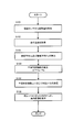
- FIG. 8 is a flowchart showing guide image display processing according to the first embodiment.
- the control unit 55 repeatedly executes the process of the flowchart shown in FIG. 8 according to a predetermined cycle.
- the control unit 55 acquires a detection signal Sd indicating the amount of vibration detected from the vibration sensor 3 (step S101). Next, the control unit 55 acquires information on the traveling speed of the vehicle Ve measured by the distance sensor 13 and the like from the navigation device 1 (step S102). Then, the control unit 55 calculates a speed average Xa that is a moving average of the past predetermined number of running speeds, and a vibration average Ya that is a moving average of the vibration amount indicated by the past predetermined number of detection signals Sd (step). S103).
- control unit 55 calculates the smoothness determination index ⁇ by referring to the equation (2) based on the calculated speed average Xa and vibration average Ya (step S104).
- control unit 55 refers to the threshold values ⁇ 1 to ⁇ 6 described with reference to FIG. 7, and determines the determination level Lv from the smoothness determination index ⁇ (step S105).
- control unit 55 determines the display size of each guide image based on the information indicating the correspondence between the determination level Lv and the display size of the guide image as illustrated in FIG. 6, and places each guide image on the combiner 9. It is displayed (step S106).
- FIG. 9 (A) shows a front scenery that the driver visually recognizes through the combiner 9 when traveling on a road with high smoothness.
- the control unit 55 includes, as a guide image, an arrow image 81 indicating a traveling direction at the next guide point to be turned right, a distance display image 82 indicating a distance to the guide point, A speed display image 83 indicating the traveling speed of the vehicle Ve is displayed on the combiner 9.
- the control unit 55 determines that the smoothness determination index ⁇ calculated with reference to the equation (2) based on the speed average Xa and the vibration average Ya is lower than the carry threshold ⁇ 2 described in FIG.
- the determination level Lv is set to level 1. Therefore, in this case, the control unit 55 displays the guide images 81 to 83 in a standard size.
- FIG. 9 (B) shows a front view viewed by the driver through the combiner 9 when traveling on a road with poor pavement.
- the control unit 55 has the smoothness determination index ⁇ calculated with reference to the equation (2) based on the speed average Xa and the vibration average Ya is equal to or higher than the carry threshold ⁇ 4 described in FIG.
- the determination level Lv is set to level 3. Therefore, in this case, the control unit 55 enlarges the arrow image 81 by a predetermined rate from the standard size and enlarges the distance display image 82 by a predetermined rate from the standard font size. By doing in this way, even if it is a case where a pavement state is bad, the arrow image 81 and the distance display image 82 can be made to visually recognize suitably.
- the control unit 55 does not enlarge the font size of the speed display image 83 indicating information with relatively low importance.
- the control unit 55 appropriately enlarges and displays only a guide image having a high priority to be visually recognized by the driver, and does not display an enlarged guide image having a low priority to be visually recognized.
- the control part 55 can ensure suitably the visual field with respect to a driver
- the control unit 55 creates a table indicating the type of guide image whose display size is changed according to the determined determination level Lv and the type of guide image whose display size is fixed regardless of the determination level Lv. Stored in advance, the display size of each guide image is determined with reference to the table.
- the head-up display 2 includes the light source unit 4 and the combiner 9.
- the control unit 55 of the light source unit 4 displays on the combiner 9 a guide image indicating characters or figures so as to overlap the scenery visually recognized from the vehicle Ve.
- the control unit 55 acquires a smoothness determination index ⁇ that is information regarding the smoothness of the road surface on which the vehicle Ve is traveling.
- the control part 55 changes the magnitude
- the head-up display 2 can change the display size of a character and a figure according to the road surface condition of a road surface, and can make a driver
- FIG. 10 shows a schematic configuration of the display system 100 according to the second embodiment.
- the control unit 55 refers to the equation (2) based on the detection signal Sd received from the vibration sensor 3 and calculates the smoothness determination index ⁇ in advance in the map data in the data storage unit 36. It differs from the first embodiment in that the smoothness determination index ⁇ is obtained by referring to the stored smoothness determination index ⁇ for each road.
- symbol is attached
- the data storage unit 36 stores, as map data, the smoothness determination index ⁇ in advance associated with each link data corresponding to each road. Then, the control unit 55 acquires the current position measured by the GPS receiver 18 or the like from the navigation device 1 to recognize the traveling road, and the smoothness determination index ⁇ associated with the link data corresponding to the recognized traveling road. Is acquired from the map data stored in the data storage unit 36. Thereafter, the control unit 55 determines the determination level Lv as in the first embodiment, and changes the display size of the guide image according to the determination level Lv.
- the control unit 55 does not need to acquire the detection signal Sd from the vibration sensor 3 and does not need to acquire the travel speed information of the vehicle Ve from the navigation device 1.
- the display size of the guide image can be determined more easily.
- map data is stored in an external server (not shown), and the head-up display 2 may acquire map information and the smoothness determination index ⁇ representing the vicinity of the current position of the vehicle Ve via the network. .
- the control unit 55 determines the estimated value of the vibration amount of the vehicle Ve (“estimated vibration” based on the smoothness determination index ⁇ acquired from the map data and the traveling speed of the vehicle Ve. Is also called “amount Ye”), and the determination level Lv is determined according to the estimated vibration amount Ye.
- control unit 55 uses the following equation (3) based on the smoothness determination index ⁇ corresponding to the traveling road acquired from the map data and the speed average Xa calculated in the same manner as in the first embodiment.
- the estimated vibration amount Ye is calculated.
- Ye ⁇ ⁇ Xa Formula (3)
- FIG. 11 is a graph showing the relationship between the average speed Xa and the estimated vibration amount Ye when the smoothness determination index ⁇ is fixed.
- the estimated vibration amount Ye that determines whether or not to increase to each level of the determination level Lv is one level lower than the carry threshold (Ye 2, Ye 4, Ye 6).
- the reduction threshold (Ye1, Ye3, Ye5) of the estimated vibration amount Ye for determining whether or not to lower the level is set to be low.
- the control unit 55 suitably suppresses frequent switching of the determination level Lv even when the estimated vibration amount Ye calculated based on Expression (3) frequently fluctuates up and down.
- FIG. 12 is a flowchart showing guide image display processing according to the third embodiment.
- the control unit 55 repeatedly executes the processing of the flowchart shown in FIG. 12 according to a predetermined cycle.
- control unit 55 acquires the current position measured by the GPS receiver 18 and the like from the navigation device 1, thereby acquiring link data corresponding to the traveling road from the map data (step S201). Then, the control unit 55 determines whether or not the smoothed determination index ⁇ is stored in association with the acquired link data (step S202).
- step S202 When the smoothness determination index ⁇ is stored in association with the acquired link data (step S202; Yes), the control unit 55 acquires the smoothness determination index ⁇ (step S203). Thereafter, the control unit 55 calculates the speed average Xa in the same manner as in the first embodiment (step S204), and calculates the estimated vibration amount Ye based on the equation (3) (step S205).
- the control unit 55 determines the determination level Lv according to the estimated vibration amount Ye (step S206). Specifically, the control unit 55 determines the determination level Lv based on the estimated vibration amount Ye calculated in step S204 and a threshold value (Ye1 to Ye6 in the example of FIG. 7) for determining the determination level Lv. . And the control part 55 displays a guidance image by the magnitude
- step S202 when the control unit 55 determines in step S202 that the smoothness determination index ⁇ is not stored in association with the corresponding link data (step S202; No), the control unit 55 uses the standard size, that is, the determination level Lv.
- the guide image is displayed with the same display size as when Level 1 is set (step S208).
- the display system 100 can display the guide image with an appropriate display size corresponding to the vibration without using the vibration sensor.
- the control unit 55 may determine the determination level Lv based on the vibration amount acquired from the vibration sensor 3 as in the third embodiment. In this case, the control unit 55 raises the vibration amount increment threshold for determining whether or not to increase to each level of the determination level Lv, and the vibration amount increment threshold for determining whether or not to lower the level one level below. Are stored in advance. Then, in the flowchart of FIG. 8, after acquiring the vibration amount from the vibration sensor 3 in Step S101, the control unit 55 does not execute Steps S102 to S104, and performs the above-described operation based on the vibration amount detected in Step S105.
- the determination level Lv is determined using the threshold value. Also according to this aspect, the control unit 55 can cause the driver to visually recognize the guide image suitably regardless of the amount of vibration of the vehicle Ve.
- the data storage unit 36 stores the determination level Lv in association with each road instead of or in addition to storing the smoothness determination index ⁇ as map data in association with each road. Also good.
- the control unit 55 determines the display size of the guide image by acquiring the determination level Lv corresponding to the traveling road from the data storage unit 36. Also according to this aspect, the control unit 55 can cause the driver to visually recognize the guide image suitably regardless of the pavement state of the traveling road.
- control unit 55 may vary the advance threshold and the advance threshold of the estimated vibration amount Ye for each road.
- the data storage unit 36 stores the above-described threshold information for determining the determination level Lv in addition to the smoothness determination index ⁇ for each link data. Then, when executing the flowchart of FIG. 12, in step S202, the control unit 55 acquires the above-described threshold value together with the smoothness determination index ⁇ from the link data, and performs determination processing of the determination level Lv in step S205.
- the data storage unit 36 stores the above-described threshold information for determining the determination level Lv for each road type such as a general road or a toll road. Then, when executing the flowchart of FIG. 12, in step S205, the control unit 55 further recognizes the type of the traveling road, and determines the determination level Lv with reference to the threshold of the determination level Lv corresponding to the recognized road type. To do.
- the number of level divisions of the determination level Lv may be different for each road.
- the level of the judgment level Lv may be two levels on a general road, and the level of the judgment level Lv may be five levels on an expressway.
- control unit 55 may vary the advance threshold and the lower threshold of the smoothness determination index ⁇ for each road.
- the control unit 55 sets the determination level Lv to level 1 without calculating the smoothness determination index ⁇ when the speed average Xa is equal to or less than a predetermined value (for example, 5 km / h). Good. Thereby, the control part 55 can prevent that the smoothness determination index
- a predetermined value for example, 5 km / h.
- the control unit 55 calculates the smoothness determination index ⁇ based on the formula (2), but the method of calculating the smoothness determination index ⁇ to which the present invention is applicable is not limited to this. Instead of this, for example, the control unit 55 calculates a smoothness determination using a more advanced expression or map defined based on an experiment or the like in order to calculate a highly accurate smoothness determination index ⁇ in accordance with the actual road surface condition.
- the index ⁇ may be calculated.
- the control unit 55 changes the display size of the guide image stepwise based on the determination level Lv. Instead of this, the control unit 55 may continuously change the display size of the guide image according to the smoothness determination index ⁇ . That is, the control unit 55 may continuously increase the display size of the guide image as the smoothness determination index ⁇ is larger. Similarly, in the third embodiment, the control unit 55 continuously changes the display size according to the estimated vibration amount Ye, instead of changing the display size of the guide image stepwise based on the determination level Lv. May be.
- the head-up display 2 has a combiner 9 and makes the driver visually recognize the virtual image Iv based on the emitted light of the light source unit 4 reflected by the combiner 9.
- the configuration to which the present invention is applicable is not limited to this.
- the head-up display 2 may not have the combiner 9 and may allow the driver to visually recognize the virtual image Iv based on the emitted light of the light source unit 4 reflected by the windshield 25.
- the windshield 25 is an example of the “display unit” in the present invention.
- the position of the light source unit 4 is not limited to the case where it is installed on the ceiling portion 27.
- the light source unit 4 may be installed on the dashboard 29 or installed inside the dashboard 29.
- the combiner 9 is provided on the dashboard 29, or light is directly reflected from the light source unit 4 on the windshield 25 to allow the driver to recognize the virtual image Iv.
- the dashboard 29 is provided with an opening for allowing light to pass through the combiner 9 or the windshield 25.
- the display system 100 may display the guide image superimposed on the front landscape using a wearable head mounted display instead of displaying the guide image superimposed on the front landscape using the head-up display 2.
- the system controller 20 may execute part of the processing of the control unit 55.
- the system controller 20 may generate a guide image for the head-up display 2 to display, and the light source unit 4 of the head-up display 2 may receive the guide image.
- the system controller 20 determines the determination level Lv by executing the flowcharts shown in FIG. 8 and FIG. 12, and is necessary for the signal or the light source 54 that specifies the display size of the guide image to emit display light. Information is transmitted to the head-up display 2. Therefore, in this modification, the system controller 20 functions as a “road surface condition acquisition unit”, “display control unit”, “speed acquisition unit”, “vibration amount acquisition unit” and a computer that executes a program in the present invention.
- the head-up display 2 may have a part or all of the functions of the navigation device 1.
- the light source unit 4 may include, for example, a memory that stores map data, sensors such as a GPS receiver, and the like.
- the control unit 55 does not change the display size of the speed display image 83, but instead, the display size of all the guide images including the speed display image 83 is set according to the determination level Lv. It may be changed.
Landscapes
- Engineering & Computer Science (AREA)
- Physics & Mathematics (AREA)
- General Physics & Mathematics (AREA)
- Optics & Photonics (AREA)
- Transportation (AREA)
- Mechanical Engineering (AREA)
- Automation & Control Theory (AREA)
- Theoretical Computer Science (AREA)
- Computer Hardware Design (AREA)
- Chemical & Material Sciences (AREA)
- Combustion & Propulsion (AREA)
- Human Computer Interaction (AREA)
- Navigation (AREA)
- Controls And Circuits For Display Device (AREA)
- Fittings On The Vehicle Exterior For Carrying Loads, And Devices For Holding Or Mounting Articles (AREA)
- Instrument Panels (AREA)
Abstract
Priority Applications (3)
| Application Number | Priority Date | Filing Date | Title |
|---|---|---|---|
| PCT/JP2014/054857 WO2015128985A1 (fr) | 2014-02-27 | 2014-02-27 | Dispositif d'affichage, procédé de commande, programme et support d'informations |
| JP2016504930A JPWO2015128985A1 (ja) | 2014-02-27 | 2014-02-27 | 表示装置、制御方法、プログラム、及び記憶媒体 |
| US15/121,145 US10147165B2 (en) | 2014-02-27 | 2014-02-27 | Display device, control method, program and recording medium |
Applications Claiming Priority (1)
| Application Number | Priority Date | Filing Date | Title |
|---|---|---|---|
| PCT/JP2014/054857 WO2015128985A1 (fr) | 2014-02-27 | 2014-02-27 | Dispositif d'affichage, procédé de commande, programme et support d'informations |
Publications (1)
| Publication Number | Publication Date |
|---|---|
| WO2015128985A1 true WO2015128985A1 (fr) | 2015-09-03 |
Family
ID=54008354
Family Applications (1)
| Application Number | Title | Priority Date | Filing Date |
|---|---|---|---|
| PCT/JP2014/054857 Ceased WO2015128985A1 (fr) | 2014-02-27 | 2014-02-27 | Dispositif d'affichage, procédé de commande, programme et support d'informations |
Country Status (3)
| Country | Link |
|---|---|
| US (1) | US10147165B2 (fr) |
| JP (1) | JPWO2015128985A1 (fr) |
| WO (1) | WO2015128985A1 (fr) |
Cited By (6)
| Publication number | Priority date | Publication date | Assignee | Title |
|---|---|---|---|---|
| JP2017087826A (ja) * | 2015-11-05 | 2017-05-25 | アルパイン株式会社 | 電子装置 |
| JPWO2017042923A1 (ja) * | 2015-09-10 | 2017-11-24 | 三菱電機株式会社 | 表示制御装置、表示装置及び表示制御方法 |
| JP2020091148A (ja) * | 2018-12-04 | 2020-06-11 | 株式会社デンソー | 表示制御装置および表示制御プログラム |
| WO2020195430A1 (fr) * | 2019-03-26 | 2020-10-01 | パナソニックIpマネジメント株式会社 | Système d'affichage d'image, corps mobile, procédé d'affichage d'image et programme |
| JP2021038979A (ja) * | 2019-09-02 | 2021-03-11 | アイシン・エィ・ダブリュ株式会社 | 重畳画像表示装置及びコンピュータプログラム |
| US11189250B2 (en) | 2017-02-28 | 2021-11-30 | Denso Corporation | Display control device and display control method |
Families Citing this family (11)
| Publication number | Priority date | Publication date | Assignee | Title |
|---|---|---|---|---|
| US10996473B2 (en) * | 2014-03-26 | 2021-05-04 | Atheer, Inc. | Method and apparatus for adjusting motion-based data space manipulation |
| US10579232B2 (en) * | 2014-07-30 | 2020-03-03 | Metra Electronics Corporation | Touchscreen-based vehicle interface |
| KR101677644B1 (ko) * | 2014-09-02 | 2016-11-29 | 엘지전자 주식회사 | 이동 단말기 및 이의 제어 방법 |
| US20160193961A1 (en) * | 2015-01-05 | 2016-07-07 | Myine Electronics, Inc. | Methods and systems for visual communication of vehicle drive information using a light set |
| US11518319B2 (en) * | 2020-01-28 | 2022-12-06 | Metra Electronics Corporation | Touchscreen-based vehicle control interface |
| CN107924668B (zh) * | 2015-08-26 | 2021-02-19 | 富士胶片株式会社 | 投影型显示装置 |
| US10206016B1 (en) * | 2016-02-19 | 2019-02-12 | Gomaco Corporation | Streaming smoothness indicator system |
| CN110099817A (zh) * | 2016-12-21 | 2019-08-06 | 富士胶片株式会社 | 投影型显示装置、投影型显示装置的控制方法、投影型显示装置的控制程序 |
| JP7172999B2 (ja) * | 2017-05-22 | 2022-11-16 | ソニーグループ株式会社 | 情報処理装置、情報処理方法及びプログラム |
| JP6919621B2 (ja) * | 2018-04-24 | 2021-08-18 | 株式会社Soken | 表示制御ユニット、及び表示制御プログラム |
| CN109741618B (zh) * | 2019-03-01 | 2021-12-21 | 湖北快嘟物流信息技术有限公司 | 一种基于远程无线定位的汽车位置标定系统 |
Citations (7)
| Publication number | Priority date | Publication date | Assignee | Title |
|---|---|---|---|---|
| JPH01293239A (ja) * | 1988-05-19 | 1989-11-27 | Canon Inc | ヘッドアップディスプレイ装置 |
| JPH06247184A (ja) * | 1993-03-01 | 1994-09-06 | Aisin Seiki Co Ltd | 車上表示装置 |
| JPH07261727A (ja) * | 1994-03-25 | 1995-10-13 | Hitachi Ltd | 情報表示装置 |
| WO2001098123A1 (fr) * | 2000-06-23 | 2001-12-27 | Kabushiki Kaisha Bridgestone | Procede d'estimation de l'etat de marche d'un vehicule, dispositif d'estimation de l'etat de marche d'un vehicule, dispositif de commande de vehicule, et bandage de roue |
| JP2007107956A (ja) * | 2005-10-12 | 2007-04-26 | Denso Corp | 車載用電子システム |
| JP2012096731A (ja) * | 2010-11-04 | 2012-05-24 | Toshiba Corp | 表示装置及び表示方法 |
| JP2014026177A (ja) * | 2012-07-27 | 2014-02-06 | Jvc Kenwood Corp | 車両用表示制御装置、車両用表示装置及び車両用表示制御方法 |
Family Cites Families (15)
| Publication number | Priority date | Publication date | Assignee | Title |
|---|---|---|---|---|
| JP3456399B2 (ja) * | 1998-02-09 | 2003-10-14 | 日産自動車株式会社 | 無段変速機の変速制御装置 |
| CN1321838C (zh) * | 2001-12-21 | 2007-06-20 | 株式会社普利司通 | 路面状况及轮胎行驶状态的推断方法和装置及利用它们的防滑刹车系统和车辆控制 |
| EP1897706B1 (fr) * | 2005-06-17 | 2014-12-24 | Kabushiki Kaisha Bridgestone | Procédé d'évaluation de l'état de la surface de la chaussée, pneu d'évaluation de l'état de la surface de la chaussée, dispositif d'évaluation de l'état de la surface de la chaussée, et dispositif de contrôle |
| JP2007210462A (ja) * | 2006-02-09 | 2007-08-23 | Mitsubishi Motors Corp | 車両用表示制御装置および車両用表示システム |
| JP4422756B2 (ja) * | 2007-12-21 | 2010-02-24 | トヨタ自動車株式会社 | 乗物用シート装置 |
| JP2010066042A (ja) | 2008-09-09 | 2010-03-25 | Toshiba Corp | 画像照射システムおよび画像照射方法 |
| JP2010070066A (ja) | 2008-09-18 | 2010-04-02 | Toshiba Corp | ヘッドアップディスプレイ |
| US20110126119A1 (en) * | 2009-11-20 | 2011-05-26 | Young Daniel J | Contextual presentation of information |
| JP5590684B2 (ja) * | 2009-12-10 | 2014-09-17 | パナソニック株式会社 | 情報表示装置及び情報表示方法 |
| WO2011099431A1 (fr) * | 2010-02-10 | 2011-08-18 | 株式会社 東芝 | Dispositif d'affichage, procédé d'affichage et corps mobile |
| US20120268568A1 (en) * | 2011-04-19 | 2012-10-25 | Qualcomm Innovation Center, Inc. | Method and apparatus of reducing visual vibration of a mobile electronic display |
| US20140331129A1 (en) * | 2011-12-15 | 2014-11-06 | Toyota Jidosha Kabushiki Kaisha | Mobile terminal device |
| CN104040610B (zh) * | 2012-01-05 | 2016-10-26 | 三菱电机株式会社 | 地图显示控制装置及使用该地图显示控制装置的导航装置 |
| GB2504311A (en) * | 2012-07-25 | 2014-01-29 | Bae Systems Plc | Head-up display using fluidic lens |
| KR101957943B1 (ko) * | 2012-08-31 | 2019-07-04 | 삼성전자주식회사 | 정보 제공 방법 및 이를 위한 정보 제공 차량 |
-
2014
- 2014-02-27 WO PCT/JP2014/054857 patent/WO2015128985A1/fr not_active Ceased
- 2014-02-27 JP JP2016504930A patent/JPWO2015128985A1/ja active Pending
- 2014-02-27 US US15/121,145 patent/US10147165B2/en active Active
Patent Citations (7)
| Publication number | Priority date | Publication date | Assignee | Title |
|---|---|---|---|---|
| JPH01293239A (ja) * | 1988-05-19 | 1989-11-27 | Canon Inc | ヘッドアップディスプレイ装置 |
| JPH06247184A (ja) * | 1993-03-01 | 1994-09-06 | Aisin Seiki Co Ltd | 車上表示装置 |
| JPH07261727A (ja) * | 1994-03-25 | 1995-10-13 | Hitachi Ltd | 情報表示装置 |
| WO2001098123A1 (fr) * | 2000-06-23 | 2001-12-27 | Kabushiki Kaisha Bridgestone | Procede d'estimation de l'etat de marche d'un vehicule, dispositif d'estimation de l'etat de marche d'un vehicule, dispositif de commande de vehicule, et bandage de roue |
| JP2007107956A (ja) * | 2005-10-12 | 2007-04-26 | Denso Corp | 車載用電子システム |
| JP2012096731A (ja) * | 2010-11-04 | 2012-05-24 | Toshiba Corp | 表示装置及び表示方法 |
| JP2014026177A (ja) * | 2012-07-27 | 2014-02-06 | Jvc Kenwood Corp | 車両用表示制御装置、車両用表示装置及び車両用表示制御方法 |
Cited By (8)
| Publication number | Priority date | Publication date | Assignee | Title |
|---|---|---|---|---|
| JPWO2017042923A1 (ja) * | 2015-09-10 | 2017-11-24 | 三菱電機株式会社 | 表示制御装置、表示装置及び表示制御方法 |
| JP2017087826A (ja) * | 2015-11-05 | 2017-05-25 | アルパイン株式会社 | 電子装置 |
| US11189250B2 (en) | 2017-02-28 | 2021-11-30 | Denso Corporation | Display control device and display control method |
| JP2020091148A (ja) * | 2018-12-04 | 2020-06-11 | 株式会社デンソー | 表示制御装置および表示制御プログラム |
| JP7206867B2 (ja) | 2018-12-04 | 2023-01-18 | 株式会社デンソー | 表示制御装置および表示制御プログラム |
| WO2020195430A1 (fr) * | 2019-03-26 | 2020-10-01 | パナソニックIpマネジメント株式会社 | Système d'affichage d'image, corps mobile, procédé d'affichage d'image et programme |
| JP2021038979A (ja) * | 2019-09-02 | 2021-03-11 | アイシン・エィ・ダブリュ株式会社 | 重畳画像表示装置及びコンピュータプログラム |
| JP7302389B2 (ja) | 2019-09-02 | 2023-07-04 | 株式会社アイシン | 重畳画像表示装置及びコンピュータプログラム |
Also Published As
| Publication number | Publication date |
|---|---|
| US10147165B2 (en) | 2018-12-04 |
| US20160371813A1 (en) | 2016-12-22 |
| JPWO2015128985A1 (ja) | 2017-03-30 |
Similar Documents
| Publication | Publication Date | Title |
|---|---|---|
| WO2015128985A1 (fr) | Dispositif d'affichage, procédé de commande, programme et support d'informations | |
| JP5964332B2 (ja) | 画像表示装置、画像表示方法及び画像表示プログラム | |
| JP2015172548A (ja) | 表示制御装置、制御方法、プログラム、及び記憶媒体 | |
| JP5735658B2 (ja) | 表示装置及び表示方法 | |
| JP5795386B2 (ja) | 表示装置及び制御方法 | |
| JP2015128956A (ja) | ヘッドアップディスプレイ、制御方法、プログラム、及び記憶媒体 | |
| JP2015141155A (ja) | 虚像表示装置、制御方法、プログラム、及び記憶媒体 | |
| JP2018128466A (ja) | ナビゲーション装置、ヘッドアップディスプレイ、制御方法、プログラム、及び記憶媒体 | |
| WO2015111213A1 (fr) | Dispositif d'affichage, procédé de commande, programme, et support d'enregistrement | |
| JP2016193723A (ja) | 表示装置、プログラム、及び記憶媒体 | |
| JP2015105903A (ja) | ナビゲーション装置、ヘッドアップディスプレイ、制御方法、プログラム、及び記憶媒体 | |
| WO2015114807A1 (fr) | Affiche d'image virtuelle, procédé de commande, programme et support de stockage | |
| WO2017086380A1 (fr) | Appareil d'affichage d'informations, procédé de commande, programme et support d'informations | |
| JP2023120221A (ja) | ヘッドアップディスプレイ、制御方法、プログラム、及び記憶媒体 | |
| JP2015127170A (ja) | ヘッドアップディスプレイ、制御方法、プログラム、及び記憶媒体 | |
| JP2023101502A (ja) | 表示装置、制御方法、プログラム、及び記憶媒体 | |
| JPWO2014097403A1 (ja) | 表示装置、制御方法、プログラム、及び記憶媒体 | |
| US20110231090A1 (en) | Map information processing device | |
| WO2013088512A1 (fr) | Dispositif d'affichage et procédé d'affichage | |
| JP2019034729A (ja) | 表示装置、制御方法、プログラム、及び記憶媒体 | |
| WO2014049705A1 (fr) | Dispositif de commande d'affichage, procédé de commande d'affichage, programme et dispositif de serveur | |
| JP7772976B2 (ja) | ナビゲーション装置、ヘッドアップディスプレイ、制御方法、プログラム、及び記憶媒体 | |
| JP6058123B2 (ja) | 表示装置、制御方法、プログラム、及び記憶媒体 | |
| WO2014002167A1 (fr) | Dispositif d'affichage d'informations, procédé d'affichage d'informations, programme d'affichage d'informations et support d'enregistrement | |
| JP2018158725A (ja) | ヘッドアップディスプレイ、制御方法、プログラム、及び記憶媒体 |
Legal Events
| Date | Code | Title | Description |
|---|---|---|---|
| 121 | Ep: the epo has been informed by wipo that ep was designated in this application |
Ref document number: 14883723 Country of ref document: EP Kind code of ref document: A1 |
|
| ENP | Entry into the national phase |
Ref document number: 2016504930 Country of ref document: JP Kind code of ref document: A |
|
| WWE | Wipo information: entry into national phase |
Ref document number: 15121145 Country of ref document: US |
|
| NENP | Non-entry into the national phase |
Ref country code: DE |
|
| 122 | Ep: pct application non-entry in european phase |
Ref document number: 14883723 Country of ref document: EP Kind code of ref document: A1 |