WO2015128986A1 - Dispositif électroluminescent à del - Google Patents
Dispositif électroluminescent à del Download PDFInfo
- Publication number
- WO2015128986A1 WO2015128986A1 PCT/JP2014/054858 JP2014054858W WO2015128986A1 WO 2015128986 A1 WO2015128986 A1 WO 2015128986A1 JP 2014054858 W JP2014054858 W JP 2014054858W WO 2015128986 A1 WO2015128986 A1 WO 2015128986A1
- Authority
- WO
- WIPO (PCT)
- Prior art keywords
- light emitting
- voltage
- light
- emitting diode
- circuit
- Prior art date
- Legal status (The legal status is an assumption and is not a legal conclusion. Google has not performed a legal analysis and makes no representation as to the accuracy of the status listed.)
- Ceased
Links
Images


Classifications
-
- H—ELECTRICITY
- H05—ELECTRIC TECHNIQUES NOT OTHERWISE PROVIDED FOR
- H05B—ELECTRIC HEATING; ELECTRIC LIGHT SOURCES NOT OTHERWISE PROVIDED FOR; CIRCUIT ARRANGEMENTS FOR ELECTRIC LIGHT SOURCES, IN GENERAL
- H05B45/00—Circuit arrangements for operating light-emitting diodes [LED]
- H05B45/40—Details of LED load circuits
- H05B45/44—Details of LED load circuits with an active control inside an LED matrix
-
- H—ELECTRICITY
- H05—ELECTRIC TECHNIQUES NOT OTHERWISE PROVIDED FOR
- H05B—ELECTRIC HEATING; ELECTRIC LIGHT SOURCES NOT OTHERWISE PROVIDED FOR; CIRCUIT ARRANGEMENTS FOR ELECTRIC LIGHT SOURCES, IN GENERAL
- H05B45/00—Circuit arrangements for operating light-emitting diodes [LED]
- H05B45/40—Details of LED load circuits
- H05B45/44—Details of LED load circuits with an active control inside an LED matrix
- H05B45/48—Details of LED load circuits with an active control inside an LED matrix having LEDs organised in strings and incorporating parallel shunting devices
Definitions
- the present invention relates to an LED light emitting device that efficiently emits light from a plurality of light emitting diodes.
- Patent Document 1 (Utility Model Registration No. 3167927) provides a constant current LED lamp that greatly simplifies the circuit architecture of the drive, uses sufficient power, reduces power loss, and eliminates electromagnetic interference.
- the constant current LED lamp is used to drive a light emitting diode of at least two series connected or a packaged polycrystalline series light emitting diode by installing a driving device. And a voltage stabilizing circuit and a constant current circuit.
- the rectifier circuit is used for receiving AC power and converting AC power to DC power.
- the filter circuit is connected to the rectifier circuit and reduces a difference in voltage amplitude of the DC power supply.
- the drive device of the present invention brings the series voltage of each light emitting diode close to the input voltage, moves each light emitting diode by the input power supply, sufficiently uses power to reduce power loss, and eliminates interference of electromagnetic waves. It is something that can be done.
- Patent Document 2 Japanese Patent Laid-Open No. 2010-563164 discloses a light emitting diode driving circuit that stably drives an LED in a wide voltage range, and a light emitting device and a lighting device using the same.
- This drive circuit drives an LED array including a plurality of LEDs connected in series, and this power supply supplies a DC drive voltage to the plurality of LEDs.
- the first constant current circuit is provided on the drive path of the plurality of LEDs, stabilizes the drive current flowing through the LEDs, the bypass switch is provided in parallel with at least one LED of the plurality of LEDs, and the control unit includes: The bypass switch is on / off controlled.
- the voltage across the constant current circuit becomes smaller and it becomes impossible to generate a predetermined constant current, and the voltage drop of each light emitting diode decreases and the luminance starts to decrease.
- the voltage across the constant current circuit increases and the voltage drop of the individual light emitting diodes increases, so that the brightness of the individual light emitting diodes can be maintained It is.
- Japanese Patent Application Laid-Open No. 2013-542550 discloses a semiconductor lighting driver and system having a total harmonic distortion bypass circuit.
- the system is an illumination drive circuit having a current drive circuit and a bypass circuit, the current drive circuit being coupled to an AC power source having an output cycle and having a first illumination segment and a second illumination segment.
- a drive circuit is configured to supply current to the power source.
- the input of the second lighting segment is directly coupled to the output of the first lighting segment, and the bypass circuit is connected to the current drive circuit and is configured to be coupled to the input of the second lighting segment, during the output cycle
- the bypass circuit is configured to supply a bypass current from the drive circuit to the second lighting segment over time.
- the total harmonic distortion bypass circuit bypasses the first illumination segment of the LED and energizes the second illumination segment, so that the semiconductor turbulence emits light for the majority of the output cycle, producing a total harmonic. Wave distortion can be reduced.
- Patent Document 4 Japanese Patent Laid-Open No. 2007-242494 discloses an AC-DC converter connected to a trademark power source, and an LED element substrate on which light-emitting diodes that emit light by a DC power source converted by the AC-DC converter are arranged.
- the light guide that diffuses the light from each light-emitting diode is charged when the trademark power supply is electrically connected, and is discharged toward the light-emitting diode when the electrical connection is broken
- LED light emitting marker device comprising: a battery power supply; a constant current supply means for supplying a constant current to the light emitting diode between the LED element substrate and the commercial power supply; and a control means for controlling an output current value of the constant current supply means. I will provide a.
- the conventional LED light-emitting devices are made to respond by changing the amount of the diode that emits light according to the fluctuation of the input voltage.
- the LED light-emitting device described in the cited document 4 is driven at a constant voltage (current) using an AC-DC converter.
- an object of the present invention to provide an LED light-emitting device that includes only an analog circuit without using an AC-DC converter.
- the present invention comprises a rectifier circuit for rectifying an AC power supply, and a light emitting diode and switch means for turning on and off the corresponding light emitting diode connected in parallel to the light emitting diode, and between the terminals of the rectifier circuit.
- a light emitting unit connected in series, a constant current circuit connected in series downstream of a plurality of light emitting units connected in series, and a minimum voltage of the constant current circuit connected in parallel to the constant current circuit
- the light emitting unit can be caused to emit light sequentially in accordance with, for example, a rise in the voltage of the rectified AC waveform due to the fluctuation of the voltage generated between the terminals of the rectifier circuit. Is something that can be done.
- the switch means is preferably a field effect transistor.
- the voltage holding means is a Zener diode.
- a light emitting diode group configured by connecting light emitting diodes in series is disposed upstream of the plurality of light emitting units.
- the number of LEDs to be lit can be controlled according to the input voltage, so that the power factor of the varying power source can be set to 1. Further, since no AC-DC converter is used, all the problems derived from the AC-DC converter described above can be avoided.
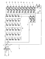
- the LED light emitting device 1 includes a rectifier circuit 3 connected to an AC power source 2 via a fuse F1.
- the rectifier circuit 3 is composed of four diodes D1 to D4.
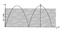
- the voltage Em generated between the output terminals 4 and 5 of the rectifier circuit 3 is rectified by the alternating current and has a waveform as shown in FIG.
- the light emitting units 6 to 45 are light emitting diodes LD1 to LD40 connected in series from the output terminal 4, respectively, and field effect transistors (FETs) connected in parallel to the light emitting diodes LD1 to LD40 to turn on and off the light emitting diode LD1. ) Q1 to Q40.
- the anode terminal of the light emitting diode LD1 of the light emitting unit 6 is connected to the output terminal 4, the cathode terminal of the light emitting diode LD1 is connected to the anode terminal of the light emitting diode LD2 of the next light emitting unit 7, and the light emitting diodes are sequentially connected in series. Connected.
- the FETs Q1 to Q40 of the light emitting units 6 to 45 are connected in parallel to the light emitting diodes LD1 to LD40 of the light emitting units 6 to 45, respectively. Further, voltage maintaining resistors R2 to R41 are provided between the gates and the sources of the FETs Q1 to Q40, respectively, and a minimum voltage (for example, 4 V) set by the resistor R1 and the Zener diode D45 is applied to the gate terminal. The Also, diodes D5 to D45 are provided at the gate terminals of the FETs Q1 to Q40 so as not to exceed the gate-drain breakdown voltage of the FETs Q1 to Q40. However, the gate and drain are clamped at the same potential by R2 to R41.
- the constant current circuit 50 includes a field effect transistor Q41, a transistor Q42, and resistors R42 and R43, and is connected to the downstream side of the light emitting units 6 to 44.
- the voltage Em between the output terminals 4 and 5 of the rectifier circuit 3 varies between 0V and 141V in the case of commercial power supply AC100V. If the voltage Em is equal to or lower than the voltage Vd (for example, 4V) set to the lowest voltage of the constant current circuit 50 by the resistor R1 and the Zener diode D45 + the driving voltage Vf (for example, 3V) of the light emitting diode, the light emitting diodes LD1 to LD40. Does not emit light.
- Vd for example, 4V
- the anode voltage of the light emitting diode LD1 becomes 10V and the cathode voltage becomes 7V, and the gate of the FET Q1 becomes higher than the voltage Vd, so the FET Q1 is turned OFF and the light emitting diode LD1.
- the anode voltage of the light emitting diode LD2 is 7V
- the cathode voltage is 4V
- the source voltage of the FET Q2 is 4V.
- the gate voltage of the FET Q2 becomes equal to the voltage Vd of the constant current circuit 50, so that the FET Q2 is turned off and the light emitting diode LD2 is lit.
- the cathode voltage of the light emitting diode LD3 becomes 1V when a current flows.
- the voltage Vd is 3V higher than the cathode voltage
- the FET Q3 is turned on, so that the light emitting diode LD3 is turned off. Since this operation occurs sequentially in the light emitting units 4 to 40, the light emitting diodes LD4 to LD40 are sequentially turned off.
- the light emitting diodes sequentially emit light. Further, when the input voltage Em decreases, the light emitting diodes are sequentially turned off. This lighting and extinction is repeated 100 times per second for 50 cycle alternating current and 120 times for 60 cycle alternating current, so that sufficient illuminance can be maintained as a whole. Furthermore, since the light emitting diode is automatically selected in accordance with the voltage fluctuation and emits light, the power factor of the power source can be set to 1.
- the LED light emitting device 1A includes a charging capacitor C2 between the output terminals 4 and 5 of the rectifier circuit 3, and a predetermined number of light emitting diodes LD41 to LD70.
- a charging capacitor C2 between the output terminals 4 and 5 of the rectifier circuit 3, and a predetermined number of light emitting diodes LD41 to LD70.
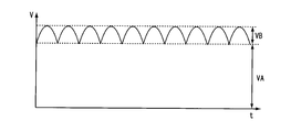
- a group of light emitting diodes 60 connected in series. Thereby, even if the input voltage Em falls to 0V, the light emitting diode group 60 is always lit by the voltage VA charged by the capacitor C2.
- light emitting units 61 to 74 are connected in series on the downstream side of the light emitting diode group 60, and a constant current circuit 50A is further connected on the downstream side thereof.
- the light emitting units 61 to 74 are configured by light emitting diodes LD71 to LD82, FETs G43 to Q54, resistors R45 to R56, and diodes D50 to D61, respectively.
- the ripple component VB of the capacitor C2 as shown in FIG. 5 is controlled by the light emitting units 61 to 74 by the operation described in the first embodiment.
- the power factor is about 0.6 to 0.7.
- the light emitting diode group 60 is always lit by the voltage VA generated by the capacitor C2, and the ripple voltage VB generated by the capacitor C2 is emitted in series with the light emitting diode group 60. It is controlled by the units 61 to 74. In other words, the light emitting units 61 to 74 emit light sequentially following the top and bottom of the ripple voltage VB and sequentially turn off. As a result, the LED light emitting device 1A according to the second embodiment can achieve the same effects as the LED light emitting device 1 of the first embodiment.
- the LED light emitting device 1B according to the third embodiment of the present invention is similar to the LED light emitting device 1A according to the second embodiment in that the light emitting diode group 80 includes the charging capacitor C3 and the light emitting diodes LD83 to LD117 connected in series. And light emitting units 81 to 88 connected in series to the downstream side of the light emitting diode group 80, and a constant current circuit 50B connected to the downstream side of the light emitting units 81 to 88.
- the LED light emitting device 1B according to the third embodiment is characterized in that the light emitting units 81 to 88 according to the third embodiment omit the gate-source resistance and the diode from the light emitting units of the first and second embodiments. It is. This is the gate of the ripple voltage FETQ61 ⁇ Q68 connected in series to the variation of VB - is obtained so as to control the breakdown voltage of the voltage V G-S between the source. This has the effect of reducing the number of parts of the light emitting portions 81 to 88.
- the present invention has a structure in which the light emission of the light emitting diode can be controlled by a change in voltage, so that the light emission of a plurality of light emitting diodes can be controlled by creating a voltage control program. It is possible to control advertising lights, indicator lights, etc. only by a pair of wires for supplying voltage. In addition, since this program can be easily configured, the burden on the CPU is low.
Landscapes
- Circuit Arrangement For Electric Light Sources In General (AREA)
Abstract
Priority Applications (2)
| Application Number | Priority Date | Filing Date | Title |
|---|---|---|---|
| JP2014512196A JPWO2015128986A1 (ja) | 2014-02-27 | 2014-02-27 | Led発光装置 |
| PCT/JP2014/054858 WO2015128986A1 (fr) | 2014-02-27 | 2014-02-27 | Dispositif électroluminescent à del |
Applications Claiming Priority (1)
| Application Number | Priority Date | Filing Date | Title |
|---|---|---|---|
| PCT/JP2014/054858 WO2015128986A1 (fr) | 2014-02-27 | 2014-02-27 | Dispositif électroluminescent à del |
Publications (1)
| Publication Number | Publication Date |
|---|---|
| WO2015128986A1 true WO2015128986A1 (fr) | 2015-09-03 |
Family
ID=54008355
Family Applications (1)
| Application Number | Title | Priority Date | Filing Date |
|---|---|---|---|
| PCT/JP2014/054858 Ceased WO2015128986A1 (fr) | 2014-02-27 | 2014-02-27 | Dispositif électroluminescent à del |
Country Status (2)
| Country | Link |
|---|---|
| JP (1) | JPWO2015128986A1 (fr) |
| WO (1) | WO2015128986A1 (fr) |
Citations (3)
| Publication number | Priority date | Publication date | Assignee | Title |
|---|---|---|---|---|
| JP2007073665A (ja) * | 2005-09-06 | 2007-03-22 | Eteitsuku:Kk | 駆動回路 |
| JP2012114236A (ja) * | 2010-11-24 | 2012-06-14 | Nichia Chem Ind Ltd | 発光ダイオード駆動装置 |
| JP2013179279A (ja) * | 2012-02-08 | 2013-09-09 | Ntt Data Intellilink Corp | 電位障壁素子制御回路及び電位障壁素子回路 |
-
2014
- 2014-02-27 JP JP2014512196A patent/JPWO2015128986A1/ja active Pending
- 2014-02-27 WO PCT/JP2014/054858 patent/WO2015128986A1/fr not_active Ceased
Patent Citations (3)
| Publication number | Priority date | Publication date | Assignee | Title |
|---|---|---|---|---|
| JP2007073665A (ja) * | 2005-09-06 | 2007-03-22 | Eteitsuku:Kk | 駆動回路 |
| JP2012114236A (ja) * | 2010-11-24 | 2012-06-14 | Nichia Chem Ind Ltd | 発光ダイオード駆動装置 |
| JP2013179279A (ja) * | 2012-02-08 | 2013-09-09 | Ntt Data Intellilink Corp | 電位障壁素子制御回路及び電位障壁素子回路 |
Also Published As
| Publication number | Publication date |
|---|---|
| JPWO2015128986A1 (ja) | 2017-03-30 |
Similar Documents
| Publication | Publication Date | Title |
|---|---|---|
| US9408265B2 (en) | Multichannel constant current LED driving circuit, driving method and LED driving power | |
| US9560704B2 (en) | LED driving device and LED lighting apparatus | |
| KR101175934B1 (ko) | 발광 다이오드 구동 회로 및 그를 이용한 교류 다이렉트 방식의 발광 다이오드 조명 장치 | |
| US9426855B2 (en) | Multi-stage LED lighting systems | |
| KR20090076330A (ko) | 시간 분할 다중 출력 직류-직류 컨버터를 갖는 발광 장치및 전원 장치 | |
| US9883559B2 (en) | Light emitting diode lighting device | |
| KR101518554B1 (ko) | 다수의 led 모듈을 구동하는 전원 공급 장치와 이를 구비하는 led 조명 장치 | |
| US8901854B1 (en) | Multi-segment LED driving circuit | |
| US9585215B2 (en) | Lighting apparatus | |
| TW201531154A (zh) | 具備多級驅動階段和低頻閃之發光二極體照明裝置 | |
| KR101160154B1 (ko) | 고조파 감쇄 기능을 갖는 단방향 led모듈 장치 | |
| JP6174647B2 (ja) | 低フリッカーの発光ダイオード照明機器 | |
| US20160119985A1 (en) | Lighting apparatus | |
| JP5739834B2 (ja) | Led照明装置及び二端子電流コントローラ | |
| US9961732B2 (en) | Control circuit for lighting apparatus | |
| KR102410680B1 (ko) | 수동 소자로 구성된 비선형 아날로그 신호 변환 회로 및 그를 이용한 조명 장치 | |
| US20180328551A1 (en) | Led lighting apparatus | |
| US10159129B2 (en) | Lighting device, illumination device, and electronic device | |
| JP2011049197A (ja) | 発光ダイオードの駆動回路、それを用いた発光装置および照明装置 | |
| KR20160094020A (ko) | 발광 다이오드 조명 장치의 제어 회로 및 제어 방법 | |
| US9648687B2 (en) | Lighting apparatus using series-connected current sources and methods of operating same | |
| WO2015128986A1 (fr) | Dispositif électroluminescent à del | |
| US20160014859A1 (en) | Led lighting apparatus | |
| KR101535115B1 (ko) | Ac직접 구동 기반의 직렬 연결형 led조명회로 | |
| US20160029452A1 (en) | Lighting apparatus |
Legal Events
| Date | Code | Title | Description |
|---|---|---|---|
| ENP | Entry into the national phase |
Ref document number: 2014512196 Country of ref document: JP Kind code of ref document: A |
|
| 121 | Ep: the epo has been informed by wipo that ep was designated in this application |
Ref document number: 14883646 Country of ref document: EP Kind code of ref document: A1 |
|
| NENP | Non-entry into the national phase |
Ref country code: DE |
|
| 32PN | Ep: public notification in the ep bulletin as address of the adressee cannot be established |
Free format text: NOTING OF LOSS OF RIGHTS PURSUANT TO RULE 112(1) EPC (EPO FORM 1205A DATED 07.12.2016) |
|
| 122 | Ep: pct application non-entry in european phase |
Ref document number: 14883646 Country of ref document: EP Kind code of ref document: A1 |